EP2351940B1 - Bearing with seal - Google Patents
Bearing with seal Download PDFInfo
- Publication number
- EP2351940B1 EP2351940B1 EP09824566.5A EP09824566A EP2351940B1 EP 2351940 B1 EP2351940 B1 EP 2351940B1 EP 09824566 A EP09824566 A EP 09824566A EP 2351940 B1 EP2351940 B1 EP 2351940B1
- Authority
- EP
- European Patent Office
- Prior art keywords
- seal
- bearing assembly
- sealing lip
- sealing
- contact
- Prior art date
- Legal status (The legal status is an assumption and is not a legal conclusion. Google has not performed a legal analysis and makes no representation as to the accuracy of the status listed.)
- Active
Links
- 238000007789 sealing Methods 0.000 claims description 136
- 230000005540 biological transmission Effects 0.000 claims description 22
- 230000015572 biosynthetic process Effects 0.000 claims description 16
- 238000005096 rolling process Methods 0.000 claims description 10
- 239000003973 paint Substances 0.000 claims description 7
- 230000000694 effects Effects 0.000 description 8
- 230000002093 peripheral effect Effects 0.000 description 7
- 239000000446 fuel Substances 0.000 description 6
- 239000000314 lubricant Substances 0.000 description 6
- 239000002184 metal Substances 0.000 description 5
- 230000002265 prevention Effects 0.000 description 5
- 238000010586 diagram Methods 0.000 description 4
- 239000000463 material Substances 0.000 description 4
- 239000002245 particle Substances 0.000 description 4
- 238000009423 ventilation Methods 0.000 description 3
- 238000010276 construction Methods 0.000 description 2
- 238000012986 modification Methods 0.000 description 2
- 230000004048 modification Effects 0.000 description 2
- 230000003746 surface roughness Effects 0.000 description 2
- 238000004381 surface treatment Methods 0.000 description 2
- 239000004519 grease Substances 0.000 description 1
- 238000000034 method Methods 0.000 description 1
- 238000000465 moulding Methods 0.000 description 1
- 239000011347 resin Substances 0.000 description 1
- 229920005989 resin Polymers 0.000 description 1
- 238000005480 shot peening Methods 0.000 description 1
Images


Classifications
-
- F—MECHANICAL ENGINEERING; LIGHTING; HEATING; WEAPONS; BLASTING
- F16—ENGINEERING ELEMENTS AND UNITS; GENERAL MEASURES FOR PRODUCING AND MAINTAINING EFFECTIVE FUNCTIONING OF MACHINES OR INSTALLATIONS; THERMAL INSULATION IN GENERAL
- F16C—SHAFTS; FLEXIBLE SHAFTS; ELEMENTS OR CRANKSHAFT MECHANISMS; ROTARY BODIES OTHER THAN GEARING ELEMENTS; BEARINGS
- F16C33/00—Parts of bearings; Special methods for making bearings or parts thereof
- F16C33/72—Sealings
- F16C33/76—Sealings of ball or roller bearings
- F16C33/78—Sealings of ball or roller bearings with a diaphragm, disc, or ring, with or without resilient members
- F16C33/784—Sealings of ball or roller bearings with a diaphragm, disc, or ring, with or without resilient members mounted to a groove in the inner surface of the outer race and extending toward the inner race
- F16C33/7843—Sealings of ball or roller bearings with a diaphragm, disc, or ring, with or without resilient members mounted to a groove in the inner surface of the outer race and extending toward the inner race with a single annular sealing disc
- F16C33/7853—Sealings of ball or roller bearings with a diaphragm, disc, or ring, with or without resilient members mounted to a groove in the inner surface of the outer race and extending toward the inner race with a single annular sealing disc with one or more sealing lips to contact the inner race
-
- F—MECHANICAL ENGINEERING; LIGHTING; HEATING; WEAPONS; BLASTING
- F16—ENGINEERING ELEMENTS AND UNITS; GENERAL MEASURES FOR PRODUCING AND MAINTAINING EFFECTIVE FUNCTIONING OF MACHINES OR INSTALLATIONS; THERMAL INSULATION IN GENERAL
- F16C—SHAFTS; FLEXIBLE SHAFTS; ELEMENTS OR CRANKSHAFT MECHANISMS; ROTARY BODIES OTHER THAN GEARING ELEMENTS; BEARINGS
- F16C33/00—Parts of bearings; Special methods for making bearings or parts thereof
- F16C33/72—Sealings
- F16C33/726—Sealings with means to vent the interior of the bearing
-
- F—MECHANICAL ENGINEERING; LIGHTING; HEATING; WEAPONS; BLASTING
- F16—ENGINEERING ELEMENTS AND UNITS; GENERAL MEASURES FOR PRODUCING AND MAINTAINING EFFECTIVE FUNCTIONING OF MACHINES OR INSTALLATIONS; THERMAL INSULATION IN GENERAL
- F16C—SHAFTS; FLEXIBLE SHAFTS; ELEMENTS OR CRANKSHAFT MECHANISMS; ROTARY BODIES OTHER THAN GEARING ELEMENTS; BEARINGS
- F16C33/00—Parts of bearings; Special methods for making bearings or parts thereof
- F16C33/72—Sealings
- F16C33/76—Sealings of ball or roller bearings
- F16C33/78—Sealings of ball or roller bearings with a diaphragm, disc, or ring, with or without resilient members
- F16C33/7816—Details of the sealing or parts thereof, e.g. geometry, material
- F16C33/782—Details of the sealing or parts thereof, e.g. geometry, material of the sealing region
- F16C33/7823—Details of the sealing or parts thereof, e.g. geometry, material of the sealing region of sealing lips
-
- F—MECHANICAL ENGINEERING; LIGHTING; HEATING; WEAPONS; BLASTING
- F16—ENGINEERING ELEMENTS AND UNITS; GENERAL MEASURES FOR PRODUCING AND MAINTAINING EFFECTIVE FUNCTIONING OF MACHINES OR INSTALLATIONS; THERMAL INSULATION IN GENERAL
- F16C—SHAFTS; FLEXIBLE SHAFTS; ELEMENTS OR CRANKSHAFT MECHANISMS; ROTARY BODIES OTHER THAN GEARING ELEMENTS; BEARINGS
- F16C19/00—Bearings with rolling contact, for exclusively rotary movement
- F16C19/02—Bearings with rolling contact, for exclusively rotary movement with bearing balls essentially of the same size in one or more circular rows
- F16C19/04—Bearings with rolling contact, for exclusively rotary movement with bearing balls essentially of the same size in one or more circular rows for radial load mainly
- F16C19/06—Bearings with rolling contact, for exclusively rotary movement with bearing balls essentially of the same size in one or more circular rows for radial load mainly with a single row or balls
-
- F—MECHANICAL ENGINEERING; LIGHTING; HEATING; WEAPONS; BLASTING
- F16—ENGINEERING ELEMENTS AND UNITS; GENERAL MEASURES FOR PRODUCING AND MAINTAINING EFFECTIVE FUNCTIONING OF MACHINES OR INSTALLATIONS; THERMAL INSULATION IN GENERAL
- F16C—SHAFTS; FLEXIBLE SHAFTS; ELEMENTS OR CRANKSHAFT MECHANISMS; ROTARY BODIES OTHER THAN GEARING ELEMENTS; BEARINGS
- F16C2361/00—Apparatus or articles in engineering in general
- F16C2361/61—Toothed gear systems, e.g. support of pinion shafts
Definitions
- the present invention relates to a seal equipped bearing assembly for use in a transmission of a type used in automotive vehicles as, for example, described in JP Laid-open Patent Publication No. 2003-287040 and in the European patent application published as EP 0 053 334 A2 .
- prior art bearing units employed in the automobile transmission are each generally employed in the form of a seal equipped bearing unit of a kind utilizing a contact type sealing member used to seal each of the opposite open ends of an annular bearing space delimited between inner and outer rings of the respective bearing unit, to thereby prevent ingress of the foreign matter into each of the bearing units.
- the sealing torque i.e., the torque, which tends to occur when each of the sealing members slidingly contacts the bearing rotatable ring and which constitutes a resistance to the rotation of the bearing unit
- the sealing torque is considerably high enough to bring about a mechanical loss of the driving torque, and this tends to pose a problem in reduction in fuel consumption of the automotive vehicle.
- Patent Document 1 JP Laid-open Patent Publication No. 2007-107588
- An object of the present invention is to provide a seal equipped bearing assembly, which is effective to assuredly avoid an undesirable ingress of foreign matter into the bearing assembly and also to achieve a sufficient reduction of the sealing torque soon after the start of use of the bearing assembly.
- the seal equipped bearing assembly is a seal equipped bearing assembly including a plurality of rolling elements interposed between opposite raceway surfaces defined in respective raceway rings and a sealing member for sealing a bearing space delimited between the raceway rings referred to above, which is characterized in that the sealing member is a contact seal, which has a base end secured to one of the raceway rings and also has a sealing lip held in sliding contact with the other of the raceway rings, and in that a gap formation facilitating element (friction facilitation treated element) capable of facilitating frictional wear of a forefront portion of the sealing lip is defined in a seal contact face of such other of the raceway rings, with which the sealing lip contacts, the gap formation facilitating element being, when used under a condition of the bearing assembly being rotated, operable to render the sealing member to be a non-contact seal or to contact so lightly that the contact pressure can assume zero.
- the sealing member is a contact seal, which has a base end secured to one of the raceway rings and also has a sealing lip held in sliding contact with the other of
- the sealing member which is the contact type at the initial stage of operation is converted into the sealing member of a non-contact type soon after the start of operation as a result of a sliding contact with the gap formation facilitating element.
- a frictional wear referred to above a light contact under a contact pressure sufficient to be regarded as zero will occur. For this reason, soon after the start of use, the sealing torque can be reduced sufficiently.
- a minute gap which defines an optimum labyrinth seal gap, can be formed between the sealing lip of the sealing member and the sealing groove of the raceway ring, an undesirable ingress of foreign matter of a particle size large enough to affect the bearing service life can be avoided while the lubricant oil can pass. As a result, an assured prevention of ingress of the foreign matter into the bearing assembly and a sufficient reduction of the sealing torque can be achieved easily.
- the raceway ring having the seal contact face is a rotatable raceway ring and a seal groove may be defined in the rotatable raceway ring and may have an inner surface which defines the seal contact face.
- the gap formation facilitating element is a minute projection provided in a circumferential portion of the seal contact face in the raceway ring, with which the sealing lip contacts. Given the minute projection, a processing to provide the gap formation facilitating element can be accomplished easily. Also, since the projection is minute, it is possible to avoid an undesirable ingress of the foreign matter which would result from floatation of the sealing lip.
- the gap formation facilitating element is a high friction paint applied area provided in the seal contact face in the raceway ring, with which the sealing lip contact. Given the high friction paint applied area, the sealing lip can be caused to contact uniformly over the entire circumference and, therefore, the frictional wear of the sealing lip occurs stably and a process to form the gap formation facilitating element can be accomplished easily.
- the sealing member may be provided with a suction preventing device for preventing the sealing member from being sucked onto such other of the raceway rings.
- the sealing lip may be provided with a slit communicated inside and outside of the sealing lip. This slit can be rendered to function as the suction preventing device. by the time the sealing member wears frictionally. Also, even after it assumes the non-contact seal, it may assume a contact state when the suction occurs.
- the provision of the suction preventing device such as, for example, the slit is effective to avoid such suction and the increase of the torque can be avoided.
- the slit referred to above air inside the bearing assembly is vented to the atmosphere and, therefore, the reduction in pressure inside the bearing assembly can be relieved and the suction is avoided to thereby avoid the increase of the torque.
- the seal contact face may be an inclined face inclined relative to a radial direction of the raceway rings, in which case the sealing lip is shaped to represent a shape allowing the sealing lip to be engaged in an axial direction with the seal contact face, defined by this inclined face. To make it an axial contact, it is easy to reduce the contact pressure at the time of contact.
- the sealing lip may be shaped to represent a shape allowing the sealing lip to be engaged in an radial direction with the seal contact face. To make it a radial contact, even when the pressure inside the bearing assembly becomes negative after the frictional wear done to a non-contact state, suction of the sealing lip can be eliminated or minimized.
- the sealing lip is so shaped as to represent a shape allowing the sealing lip to be engaged in the axial direction with the seal contact face, such slit has to be provided along the seal contact face, which defines the inclined face, so as to permit the space inside the bearing assembly to be communicated inside and outside through such slit.
- the sealing lip is so shaped as to represent a shape allowing the sealing lip to be engaged in the radial direction with the seal contact face, such slit has to be provided along the seal contact face, which defines, for example, the cylindrical face, so as to permit the space inside the bearing assembly to be communicated inside and outside through such slit.
- the seal equipped bearing assembly of the present invention may be used as a bearing assembly for a transmission, which is used to support a drive transmitting shaft of the transmission for use in automotive vehicles.
- the drive transmitting shaft may be any one of an input shaft, an output shaft and an intermediate transmission shaft.
- the bearing assembly for use in automobile transmissions is strongly required to be so configured as to ensure an assured prevention of ingress of foreign matter into the bearing assembly and, also, a reduction of the sealing torque and, therefore, effects of the present invention can be effectively exhibited.
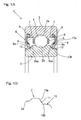
- the seal equipped bearing assembly 1 is a rolling bearing assembly that is used in a transmission for an automotive vehicle and includes a plurality of rolling elements 4 interposed between raceway surfaces 2a and 3a defined in an inner ring 2 and an outer ring 3, respectively, a retainer 5 for retaining those rolling elements 4, and a sealing member 6 for sealing each of the opposite ends of an annular bearing space delimited between the inner and outer rings 2 and 3.
- the inner ring 2 and the outer ring 3 form a pair of raceway rings referred to in the appended claims.
- a grease is initially filled in the bearing assembly.
- This rolling bearing assembly is a deep groove ball bearing, in which the rolling elements 4 are employed in the form of balls, and is of an inner ring rotating type, in which the inner ring 2 is used as a rotatable ring and the outer ring 3 is used as a stationary ring.
- the sealing member 6 is made up of an annular core metal 7 and an elastic member 8 made of a rubber or resin material or the like secured integrally to the core metal 7 and has an outer peripheral portion thereof fixedly engaged in a seal mounting groove 8 defined in an inner peripheral surface of the outer ring 3 that serves as the stationary ring.
- the sealing member 6 in its entirety is formed by molding and vulcanizing the rubber material to the core metal 7.
- the inner ring 2 that serves as the rotatable ring has a seal groove 10 in the form of a circumferentially extending groove at a location corresponding to an inner peripheral portion of each of the sealing members 6.
- the seal groove 10 is, in the instance as shown, of a sectional shape including a sealing face 10a, which is rendered to be an inclined face inclined downwardly from a shoulder of the raceway surface 2a, and a groove bottom face 10b in the form of a cylindrical face continued from an inner peripheral edge of the sealing face 10a to an inner ring end face.
- the seal groove 10 may be of a U-sectioned configuration and may have opposite peripheral faces, each continued to each of the opposite sides of the groove of the U-sectioned configuration or the like, which have respective diameters that are different from each other.
- the sealing member 6 is formed with a sealing lip 8aa formed in a forefront portion of an elastic member inner peripheral portion 8a, which extends radially inwardly from the core metal 7 of the elastic member 8.
- This sealing lip 8aa has a forefront portion is held in sliding engagement with the sealing face 10a of the seal groove 10 in the inner ring 1.
- the sealing lip 8aa extends inwardly of the bearing assembly as shown in Fig. 3A and is held in engagement in an axial direction with the sealing face 10a that is defined by the inclined face forming an inner wall face of the seal groove 10.
- the sealing lip 8aa has a wall thickness that is not bigger than half of, for example, 1/4 of the wall thickness of the elastic member inner peripheral portion 8a.
- This minute projection 11 may be provided in a plural number and distributed at even intervals over the entire circumference of the inner ring 2 or provided at one location.
- This minute projection 11 has a height so chosen as to be smaller than the particle size of foreign matter which, when intruding inside the bearing assembly, will affect the service life of the bearing assembly.
- the forefront portion of the sealing lip 8aa of the sealing member 6 is, as shown in an enlarged sectional view in Fig. 3B , provided with a slit 12 for ventilation purpose.
- This slit 12 may be provided at one location or a plurality of locations in the circumferential direction thereof.
- This slit 12 will serve as a suction preventing device for the sealing lip 8bb and allows the space inside the bearing assembly to be communicated inside and outside while the sealing lip 8aa is held in contact with the sealing face 10a.
- the phenomenon, in which the sealing member 6 is sucked towards the inner ring 2 by the effect of a reduction in internal pressure incident to operation of the bearing assembly, is prevented by the ventilation accomplished by the slit 12.
- the sealing member 6 which is the contact type in the initial stage of operation of the bearing assembly, can become the non-contact type soon after the start of operation of the bearing assembly, for example, a few minutes subsequent to the start of operation of the bearing assembly as a result of sliding engagement of the forefront portion of the sealing lip 8aa with the sealing face 10a and, therefore, the sealing torque can be reduced sufficiently.
- Fig. 4 illustrates a chart showing changes of the rotational torque (the torque necessary to rotate the bearing assembly) of the seal equipped bearing assembly 1 according to the above described first embodiment and the bearing temperature (outer ring temperature) with time
- Fig. 5 illustrates a chart showing changes of the rotational torque of the seal equipped bearing assembly and the bearing temperature with time that is exhibited by the conventional product, shown for the purpose comparison.
- the graph shown in a lower portion of the chart represents the rotational torque
- the graph shown in an upper portion of the chart represents the bearing temperature.
- the forefront portion of the sealing lip 8aa is frictionally worn out a few minutes subsequent to the start of operation of the bearing assembly to thereby form the optimum labyrinth gap, the sealing torque, which has occupies a large proportion of the bearing torque (torque that forms the resistance to rotation of the bearing assembly), can be eliminated and, therefore, the rotational torque is reduced considerably. Also, incident thereto, temperature self-increase of the bearing assembly is lowered.
- the forefront portion of the sealing lip 8aa of the sealing member 6 is provided with the ventilating slit 12 defining the suction preventing device in order to prevent the sealing member 6 from being sucked onto the inner ring 1 which would occur as a result of reduction in internal pressure of the bearing assembly, the possibility that after the sealing member 6 then worn out has become the non-contact seal, the sealing member 6 is sucked onto the seal groove 10 in the inner ring 2 to assume a contact seal by the effect of the reduction in internal pressure of the bearing assembly or the possibility that the sealing member 6 is strongly sucked onto the seal groove 10 by the time the sealing member 6 is worn out can be prevented and, therefore, an undesirable increase of the torque resulting from the suction can be avoided.
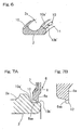
- Figs. 6, 7A and 7B illustrate a second preferred embodiment of the present invention.
- the forefront portion of the sealing lip 8aa of the sealing member 6 is made to extend inwardly and is then held in engagement in a radial direction with a sealing face, which is a groove bottom face 10b' of the seal groove 10 defined in the inner ring 2 as best shown in Fig. 7A .
- the sectional shape of the seal groove 10 is the same as that employed in the practice of the first embodiment shown in and described with particular reference to Figs. 1A and 1B to 5 , but the groove bottom face 10b' serves as the sealing face and an inclined face 10a' is rendered to be non-contact.
- the groove bottom face 10b' of the seal groove 10 serves as the sealing face with which the forefront portion of the sealing lip 8aa contacts, the minute projection 11 defining the gap formation facilitating element is formed, as shown in Fig. 6 , in the sealing face defined by the groove bottom face 10b' of the seal groove 10.
- the forefront portion of the sealing lip 8aa of the sealing member 6 is provided with a slit 12 for ventilation purpose, which defines the suction preventing device.
- Other structural features thereof than those described above are similar to those shown and described in connection with the previously described first embodiment.
- the use of the minute projection 11 in that circumferential portion of the groove bottom face 10b', which defines the sealing face or the sealing face 10a of the inner ring 2, which defines the rotatable raceway ring, has been shown and exemplified as the gap formation facilitating element operable to facilitate a frictional wear of the forefront portion of the sealing lip 8aa of the sealing member 6, a high friction paint may be applied to the groove bottom face 10b', which defines the sealing face or the sealing face 10a referred to above in place of the minute projection 11, to thereby form a high friction paint applied area.
- a Parker Processing may be enumerated.
- the Parker Processing referred to above is one of surface treatments, which is generally called the Papro Fric Processing (Metal Surface Treatment With High Frictional Coefficient Non-Lubricant Paint) provided for by Parker Kako Co., Ltd.
- the elastic member 8 has been shown and described as made of the same material in its entirety, the sealing lip 8aa in its entirety or the forefront portion of the sealing lip 8aa may be made of a material that is easier to wear frictionally than that of any other portion thereof.
- the present invention has been shown and described as applied to the rolling bearing assembly of the inner ring rotating type, the present invention can be equally applied to a rolling bearing assembly of an outer ring rotating type or a thrust bearing assembly and, even in such case, effects similar to those described hereinbefore can be obtained.
- Fig. 8 illustrates a schematic diagram showing one example of a gear system employed in the transmission for use in automotive vehicle, in which the seal equipped bearing assembly 1 of the present invention is incorporated. Shown therein is, for example, a manual transmission.
- An input shaft 31 is rotatably supported by a housing 35A through the seal equipped bearing assembly 1 according to any one of the previously described first and second embodiments of the present invention.
- An output shaft 32 has one end rotatably supported by an end inner diametric surface of the input shaft 31 through a rolling bearing assembly 34 and also has the opposite end rotatably supported by the housing 35b through the seal equipped bearing assembly 1.
- a counter shaft 33 having gears 39, 40, 41 and 42 engageable respectively with a gear 36 on the input shaft 31 and gears 37 and 38 on the output shaft 32 is arranged parallel to the output shaft 32 and has its opposite ends rotatably supported by respective housings 35A and 35B.
- the use of the seal equipped bearing assembly 1 of the present invention in the automobile transmission prevention of ingress of the foreign matter into the bearing assembly and sufficient reduction of the sealing torque can be accomplished and, hence, it is possible to contribute to the reduction in fuel consumption of the automotive vehicle.
- Fig. 9 illustrates a schematic diagram showing a different example of a gear system employed in the transmission for use in automotive vehicle, in which the seal equipped bearing assembly 1 of the present invention is incorporated. Shown therein is, for example, an automatic transmission. Opposite ends of a main shaft 51 is rotatably supported by a casing 53 through the seal equipped bearing assembly 1 according to any one of the previously described first and second embodiments of the present invention. A counter shaft 52 having a gear system engageable with a gear system on the main shaft 51 is also rotatably supported by the casing 53 and arranged parallel to the main shaft 51.
Description
- This application is based on and claims Convention priority to Japanese patent application No.
2008-285574, filed November 6, 2008 - The present invention relates to a seal equipped bearing assembly for use in a transmission of a type used in automotive vehicles as, for example, described in
JP Laid-open Patent Publication No. 2003-287040 EP 0 053 334 A2 - The transmission used in automotive vehicles generally contains foreign matter such as wear debris resulting from gears employed therein. For this reason, prior art bearing units employed in the automobile transmission are each generally employed in the form of a seal equipped bearing unit of a kind utilizing a contact type sealing member used to seal each of the opposite open ends of an annular bearing space delimited between inner and outer rings of the respective bearing unit, to thereby prevent ingress of the foreign matter into each of the bearing units.
- Where the annular bearing space is sealed at its opposite open ends with the respective contact type sealing members, an undesirable ingress of the foreign matter can be successfully prevented, but the sealing torque (i.e., the torque, which tends to occur when each of the sealing members slidingly contacts the bearing rotatable ring and which constitutes a resistance to the rotation of the bearing unit) is considerably high enough to bring about a mechanical loss of the driving torque, and this tends to pose a problem in reduction in fuel consumption of the automotive vehicle.
- In the seal equipped bearing unit of the kind discussed above, it has been suggested to reduce the sealing torque (in, for example, the
Patent Document 1 listed below) by effecting a shot peening a surface of one or more sealing lips of each of the sealing member, for example, an inner wall surface of a seal groove defined in the bearing rotatable ring, to render the contact surface to have a surface roughness not larger than 2.5 µm at the maximum height of irregularities Ry. - [Patent Document 1]
JP Laid-open Patent Publication No. 2007-107588 - According to the reduction of the surface roughness of the contact surface to thereby reduce the sealing torque such as employed in the seal equipped bearing unit disclosed in the
Patent Document 1 listed above, the extent to which the torque is reduced is limited and no satisfactory effect of reducing the torque can be obtained. Although the use of a non-contact seal will be effective to reduce the sealing torque to zero, reduction in size of the seal gap to such an extent that the undesirable ingress of the foreign matter such as, for example, wear debris resulting from the transmission gears can be prevented will be difficult to achieve because of an error in assemblage, an error in processing, difference in thermal expansion and some other factors. - An object of the present invention is to provide a seal equipped bearing assembly, which is effective to assuredly avoid an undesirable ingress of foreign matter into the bearing assembly and also to achieve a sufficient reduction of the sealing torque soon after the start of use of the bearing assembly.
- The seal equipped bearing assembly according to the present invention is a seal equipped bearing assembly including a plurality of rolling elements interposed between opposite raceway surfaces defined in respective raceway rings and a sealing member for sealing a bearing space delimited between the raceway rings referred to above, which is characterized in that the sealing member is a contact seal, which has a base end secured to one of the raceway rings and also has a sealing lip held in sliding contact with the other of the raceway rings, and in that a gap formation facilitating element (friction facilitation treated element) capable of facilitating frictional wear of a forefront portion of the sealing lip is defined in a seal contact face of such other of the raceway rings, with which the sealing lip contacts, the gap formation facilitating element being, when used under a condition of the bearing assembly being rotated, operable to render the sealing member to be a non-contact seal or to contact so lightly that the contact pressure can assume zero.
- According to the foregoing construction, since the gap formation facilitating element for facilitating a wear of a forefront portion of the sealing lip is provided in the sealing face of the raceway ring with which the sealing lip contacts slidingly, the sealing member, which is the contact type at the initial stage of operation is converted into the sealing member of a non-contact type soon after the start of operation as a result of a sliding contact with the gap formation facilitating element. Or, by the effect of a frictional wear referred to above, a light contact under a contact pressure sufficient to be regarded as zero will occur. For this reason, soon after the start of use, the sealing torque can be reduced sufficiently. By way of example, within a few minutes subsequent to the start of operation, non-contact or the light contact under a contact pressure that can be regarded as zero occurs. As a result, reduction in temperature rise of the bearing assembly can be accomplished and a lubricant oil having a viscosity further lower than that hitherto employed can be selected. Particularly where it is used in a transmission for use in automotive vehicle, it can contribute to reduction in fuel consumption of the automotive vehicle.
- Also, since by the effect of the frictional wear referred to above, a minute gap, which defines an optimum labyrinth seal gap, can be formed between the sealing lip of the sealing member and the sealing groove of the raceway ring, an undesirable ingress of foreign matter of a particle size large enough to affect the bearing service life can be avoided while the lubricant oil can pass. As a result, an assured prevention of ingress of the foreign matter into the bearing assembly and a sufficient reduction of the sealing torque can be achieved easily.
- In the practice of the present invention, the raceway ring having the seal contact face is a rotatable raceway ring and a seal groove may be defined in the rotatable raceway ring and may have an inner surface which defines the seal contact face. The provision of the sealing groove to allow the sealing lip to contact within this sealing groove is effective to enhance a sealing effect. For this reason, even when it becomes a non-contact seal as a result of frictional wear of the sealing lip, an assured sealability can be secured.
- According to one alternative of the present invention, the gap formation facilitating element is a minute projection provided in a circumferential portion of the seal contact face in the raceway ring, with which the sealing lip contacts. Given the minute projection, a processing to provide the gap formation facilitating element can be accomplished easily. Also, since the projection is minute, it is possible to avoid an undesirable ingress of the foreign matter which would result from floatation of the sealing lip.
- According to another alternative of the present invention, the gap formation facilitating element is a high friction paint applied area provided in the seal contact face in the raceway ring, with which the sealing lip contact. Given the high friction paint applied area, the sealing lip can be caused to contact uniformly over the entire circumference and, therefore, the frictional wear of the sealing lip occurs stably and a process to form the gap formation facilitating element can be accomplished easily.
- In the practice of the present invention, the sealing member may be provided with a suction preventing device for preventing the sealing member from being sucked onto such other of the raceway rings. Also, the sealing lip may be provided with a slit communicated inside and outside of the sealing lip. This slit can be rendered to function as the suction preventing device. by the time the sealing member wears frictionally. Also, even after it assumes the non-contact seal, it may assume a contact state when the suction occurs. The provision of the suction preventing device such as, for example, the slit is effective to avoid such suction and the increase of the torque can be avoided. Where the slit referred to above is employed, air inside the bearing assembly is vented to the atmosphere and, therefore, the reduction in pressure inside the bearing assembly can be relieved and the suction is avoided to thereby avoid the increase of the torque.
- In the practice of the present invention, the seal contact face may be an inclined face inclined relative to a radial direction of the raceway rings, in which case the sealing lip is shaped to represent a shape allowing the sealing lip to be engaged in an axial direction with the seal contact face, defined by this inclined face. To make it an axial contact, it is easy to reduce the contact pressure at the time of contact.
- Also, the sealing lip may be shaped to represent a shape allowing the sealing lip to be engaged in an radial direction with the seal contact face. To make it a radial contact, even when the pressure inside the bearing assembly becomes negative after the frictional wear done to a non-contact state, suction of the sealing lip can be eliminated or minimized.
- Where the minute projection referred to above is employed, and if the sealing lip is so shaped as to represent a shape allowing the sealing lip to be engaged in the axial direction with the seal contact face, such minute projection has to be provided in the seal contact face that defines the inclined face. On the other hand, where the minute projection referred to above is employed, and if the sealing lip is so shaped as to represent a shape allowing the sealing lip to be engaged in the radial direction with the seal contact face, such minute projection has to be provided in the seal contact face that defines, for example, a cylindrical face thereof.
- Where the slit referred to above is employed, and if the sealing lip is so shaped as to represent a shape allowing the sealing lip to be engaged in the axial direction with the seal contact face, such slit has to be provided along the seal contact face, which defines the inclined face, so as to permit the space inside the bearing assembly to be communicated inside and outside through such slit. On the other hand, where the slit referred to above is employed, and if the sealing lip is so shaped as to represent a shape allowing the sealing lip to be engaged in the radial direction with the seal contact face, such slit has to be provided along the seal contact face, which defines, for example, the cylindrical face, so as to permit the space inside the bearing assembly to be communicated inside and outside through such slit.
- The seal equipped bearing assembly of the present invention may be used as a bearing assembly for a transmission, which is used to support a drive transmitting shaft of the transmission for use in automotive vehicles. The drive transmitting shaft may be any one of an input shaft, an output shaft and an intermediate transmission shaft.
- The bearing assembly for use in automobile transmissions is strongly required to be so configured as to ensure an assured prevention of ingress of foreign matter into the bearing assembly and, also, a reduction of the sealing torque and, therefore, effects of the present invention can be effectively exhibited.
- In any event, the present invention will become more clearly understood from the following description of preferred embodiments thereof, when taken in conjunction with the accompanying drawings. However, the embodiments and the drawings are given only for the purpose of illustration and explanation, and are not to be taken as limiting the scope of the present invention in any way whatsoever, which scope is to be determined by the appended claims.
In the accompanying drawings, like reference numerals are used to denote like parts throughout the several views, and: -
Fig. 1A is a sectional view showing a seal equipped bearing assembly according to a first preferred embodiment of the present invention; -
Fig. 1B is a fragmentary enlarged view of a portion ofFig. 1A ; -
Fig. 2 is a fragmentary perspective view showing an inner ring employed in the seal equipped bearing assembly; -
Fig. 3A is a fragmentary enlarged sectional view showing a seal member contact area in the seal equipped bearing assembly; -
Fig. 3B is a fragmentary enlarged sectional view showing the seal member; -
Fig. 4 is a chart showing changes of the rotational torque of the seal equipped bearing assembly and the bearing temperature with time; -
Fig. 5 is a chart showing changes of the rotational torque of the seal equipped bearing assembly and the bearing temperature with time that is exhibited by the conventional product; -
Fig. 6 is a fragmentary perspective view showing the inner ring employed in the seal equipped bearing assembly according to a second preferred embodiment of the present invention; -
Fig. 7A is a fragmentary enlarged sectional view showing the seal member contact area in the seal equipped bearing assembly; -
Fig. 7B is a fragmentary enlarged sectional view showing the seal member; -
Fig. 8 is a schematic diagram showing one example of a gear system in a transmission for an automotive vehicle, in which the seal equipped bearing assembly of the present invention is incorporated; and -
Fig. 9 is a schematic diagram showing another example of a gear system in a transmission for an automotive vehicle, in which the seal equipped bearing assembly of the present invention is incorporated. - A first preferred embodiment of the present invention will be described in detail with particular reference to
Figs. 1A and 1B toFig. 5 . The seal equippedbearing assembly 1 according to the first embodiment is a rolling bearing assembly that is used in a transmission for an automotive vehicle and includes a plurality of rollingelements 4 interposed betweenraceway surfaces inner ring 2 and anouter ring 3, respectively, aretainer 5 for retaining those rollingelements 4, and a sealingmember 6 for sealing each of the opposite ends of an annular bearing space delimited between the inner andouter rings inner ring 2 and theouter ring 3 form a pair of raceway rings referred to in the appended claims. A grease is initially filled in the bearing assembly. This rolling bearing assembly is a deep groove ball bearing, in which the rollingelements 4 are employed in the form of balls, and is of an inner ring rotating type, in which theinner ring 2 is used as a rotatable ring and theouter ring 3 is used as a stationary ring. - The sealing
member 6 is made up of anannular core metal 7 and anelastic member 8 made of a rubber or resin material or the like secured integrally to thecore metal 7 and has an outer peripheral portion thereof fixedly engaged in aseal mounting groove 8 defined in an inner peripheral surface of theouter ring 3 that serves as the stationary ring. The sealingmember 6 in its entirety is formed by molding and vulcanizing the rubber material to thecore metal 7. - The
inner ring 2 that serves as the rotatable ring has aseal groove 10 in the form of a circumferentially extending groove at a location corresponding to an inner peripheral portion of each of the sealingmembers 6. Theseal groove 10 is, in the instance as shown, of a sectional shape including a sealingface 10a, which is rendered to be an inclined face inclined downwardly from a shoulder of theraceway surface 2a, and a groovebottom face 10b in the form of a cylindrical face continued from an inner peripheral edge of the sealingface 10a to an inner ring end face. It is to be noted that although not shown, theseal groove 10 may be of a U-sectioned configuration and may have opposite peripheral faces, each continued to each of the opposite sides of the groove of the U-sectioned configuration or the like, which have respective diameters that are different from each other. - The sealing
member 6 is formed with a sealing lip 8aa formed in a forefront portion of an elastic member innerperipheral portion 8a, which extends radially inwardly from thecore metal 7 of theelastic member 8. This sealing lip 8aa has a forefront portion is held in sliding engagement with the sealingface 10a of theseal groove 10 in theinner ring 1. In the first embodiment of the present invention, the sealing lip 8aa extends inwardly of the bearing assembly as shown inFig. 3A and is held in engagement in an axial direction with the sealingface 10a that is defined by the inclined face forming an inner wall face of theseal groove 10. The sealing lip 8aa has a wall thickness that is not bigger than half of, for example, 1/4 of the wall thickness of the elastic member innerperipheral portion 8a. - As best shown in
Fig. 2 , a circumferential portion of the sealingface 10a of theinner ring 2, that is within the width or radial range over which the sealing lip 8aa is slidingly engaged, is formed with aminute projection 11 that defines a gap formation facilitating element capable of facilitating frictional wear of the forefront portion of the sealing lip 8aa. Thisminute projection 11 may be provided in a plural number and distributed at even intervals over the entire circumference of theinner ring 2 or provided at one location. Thisminute projection 11 has a height so chosen as to be smaller than the particle size of foreign matter which, when intruding inside the bearing assembly, will affect the service life of the bearing assembly. - Also, the forefront portion of the sealing lip 8aa of the sealing
member 6 is, as shown in an enlarged sectional view inFig. 3B , provided with aslit 12 for ventilation purpose. This slit 12 may be provided at one location or a plurality of locations in the circumferential direction thereof. This slit 12 will serve as a suction preventing device for the sealing lip 8bb and allows the space inside the bearing assembly to be communicated inside and outside while the sealing lip 8aa is held in contact with the sealingface 10a. The phenomenon, in which the sealingmember 6 is sucked towards theinner ring 2 by the effect of a reduction in internal pressure incident to operation of the bearing assembly, is prevented by the ventilation accomplished by theslit 12. - According to the seal equipped
bearing assembly 1 of the construction described hereinabove, since theminute projection 11 as the gap formation facilitating element for facilitating the frictional wear of the forefront portion of the sealing lip 8aa is provided in the sealingface 10a of theinner ring 2 with which the sealing lip 8aa of the sealingmember 6 is slidingly engaged, the sealingmember 6, which is the contact type in the initial stage of operation of the bearing assembly, can become the non-contact type soon after the start of operation of the bearing assembly, for example, a few minutes subsequent to the start of operation of the bearing assembly as a result of sliding engagement of the forefront portion of the sealing lip 8aa with the sealingface 10a and, therefore, the sealing torque can be reduced sufficiently. - Accordingly, a sufficient reduction of the sealing torque can be accomplished. As a result thereof, it is possible to reduce the temperature increase of the bearing assembly and, hence, a lubricant oil of a viscosity further lower than that of the lubricant oil hitherto used can be selected. Particularly where it is applied in a transmission used in automotive vehicles, it is expected to contribute to the reduction in fuel consumption of the automotive vehicle.
- Also, since by the above described frictional wear a minute gap, which forms an optimum labyrinth seal gap, is formed between the sealing lip 8aa of the sealing
member 6 and theseal groove 10 in theinner ring 2, an undesirable intrusion of foreign matter of a particle size large enough to affect the bearing service life can be prevented although the lubricant oil can pass therethrough. Since while theminute projection 11, which will form the gap formation facilitating element, is provided in theseal groove 10, theminute projection 11 has a height so chosen as to be smaller than the particle size of the foreign matter, which will affect the bearing service life, it will not constitute a cause of intrusion of the foreign matter into the bearing assembly. -
Fig. 4 illustrates a chart showing changes of the rotational torque (the torque necessary to rotate the bearing assembly) of the seal equippedbearing assembly 1 according to the above described first embodiment and the bearing temperature (outer ring temperature) with time, whileFig. 5 illustrates a chart showing changes of the rotational torque of the seal equipped bearing assembly and the bearing temperature with time that is exhibited by the conventional product, shown for the purpose comparison. Referring toFigs. 4 and 5 , the graph shown in a lower portion of the chart represents the rotational torque whereas the graph shown in an upper portion of the chart represents the bearing temperature. As shown inFig. 4 , as compared with the conventional product, since in the seal equippedbearing assembly 1 according to the above described first embodiment of the present invention, the forefront portion of the sealing lip 8aa is frictionally worn out a few minutes subsequent to the start of operation of the bearing assembly to thereby form the optimum labyrinth gap, the sealing torque, which has occupies a large proportion of the bearing torque (torque that forms the resistance to rotation of the bearing assembly), can be eliminated and, therefore, the rotational torque is reduced considerably. Also, incident thereto, temperature self-increase of the bearing assembly is lowered. - In addition, since in the above described first embodiment, the forefront portion of the sealing lip 8aa of the sealing
member 6 is provided with the ventilating slit 12 defining the suction preventing device in order to prevent the sealingmember 6 from being sucked onto theinner ring 1 which would occur as a result of reduction in internal pressure of the bearing assembly, the possibility that after the sealingmember 6 then worn out has become the non-contact seal, the sealingmember 6 is sucked onto theseal groove 10 in theinner ring 2 to assume a contact seal by the effect of the reduction in internal pressure of the bearing assembly or the possibility that the sealingmember 6 is strongly sucked onto theseal groove 10 by the time the sealingmember 6 is worn out can be prevented and, therefore, an undesirable increase of the torque resulting from the suction can be avoided. -
Figs. 6, 7A and 7B illustrate a second preferred embodiment of the present invention. In the seal equipped bearing assembly according to the second embodiment, unlike that according to the first embodiment shown in and described with reference toFigs. 1A and1B to 5 , the forefront portion of the sealing lip 8aa of the sealingmember 6 is made to extend inwardly and is then held in engagement in a radial direction with a sealing face, which is a groovebottom face 10b' of theseal groove 10 defined in theinner ring 2 as best shown inFig. 7A . It is to be noted that the sectional shape of theseal groove 10 is the same as that employed in the practice of the first embodiment shown in and described with particular reference toFigs. 1A and1B to 5 , but the groovebottom face 10b' serves as the sealing face and aninclined face 10a' is rendered to be non-contact. - Also, since in the second embodiment, the groove
bottom face 10b' of theseal groove 10 serves as the sealing face with which the forefront portion of the sealing lip 8aa contacts, theminute projection 11 defining the gap formation facilitating element is formed, as shown inFig. 6 , in the sealing face defined by the groovebottom face 10b' of theseal groove 10. Even in this second embodiment of the present invention, as shown in an enlarged sectional view inFig. 7B , the forefront portion of the sealing lip 8aa of the sealingmember 6 is provided with aslit 12 for ventilation purpose, which defines the suction preventing device. Other structural features thereof than those described above are similar to those shown and described in connection with the previously described first embodiment. - Even in this second embodiment of the present invention, prevention of the foreign matter from entering the bearing assembly and sufficient reduction of the sealing torque can be accomplished and, where it is applied in a transmission used in automotive vehicles, it is expected to contribute to the reduction in fuel consumption of the automotive vehicle.
- It is to be noted that although in describing each of the foregoing preferred embodiments of the present invention, the use of the
minute projection 11 in that circumferential portion of the groovebottom face 10b', which defines the sealing face or the sealingface 10a of theinner ring 2, which defines the rotatable raceway ring, has been shown and exemplified as the gap formation facilitating element operable to facilitate a frictional wear of the forefront portion of the sealing lip 8aa of the sealingmember 6, a high friction paint may be applied to the groovebottom face 10b', which defines the sealing face or the sealingface 10a referred to above in place of theminute projection 11, to thereby form a high friction paint applied area. In such case, for the high friction paint, a Parker Processing may be enumerated. The Parker Processing referred to above is one of surface treatments, which is generally called the Papro Fric Processing (Metal Surface Treatment With High Frictional Coefficient Non-Lubricant Paint) provided for by Parker Kako Co., Ltd. - Also, although in describing each of the foregoing embodiments, the
elastic member 8 has been shown and described as made of the same material in its entirety, the sealing lip 8aa in its entirety or the forefront portion of the sealing lip 8aa may be made of a material that is easier to wear frictionally than that of any other portion thereof. - Also, although in describing each of the foregoing embodiments, the present invention has been shown and described as applied to the rolling bearing assembly of the inner ring rotating type, the present invention can be equally applied to a rolling bearing assembly of an outer ring rotating type or a thrust bearing assembly and, even in such case, effects similar to those described hereinbefore can be obtained.
-
Fig. 8 illustrates a schematic diagram showing one example of a gear system employed in the transmission for use in automotive vehicle, in which the seal equippedbearing assembly 1 of the present invention is incorporated. Shown therein is, for example, a manual transmission. Aninput shaft 31 is rotatably supported by ahousing 35A through the seal equippedbearing assembly 1 according to any one of the previously described first and second embodiments of the present invention. Anoutput shaft 32 has one end rotatably supported by an end inner diametric surface of theinput shaft 31 through a rollingbearing assembly 34 and also has the opposite end rotatably supported by the housing 35b through the seal equippedbearing assembly 1. Acounter shaft 33 havinggears gear 36 on theinput shaft 31 and gears 37 and 38 on theoutput shaft 32 is arranged parallel to theoutput shaft 32 and has its opposite ends rotatably supported byrespective housings - As hereinabove described, the use of the seal equipped
bearing assembly 1 of the present invention in the automobile transmission, prevention of ingress of the foreign matter into the bearing assembly and sufficient reduction of the sealing torque can be accomplished and, hence, it is possible to contribute to the reduction in fuel consumption of the automotive vehicle. -
Fig. 9 illustrates a schematic diagram showing a different example of a gear system employed in the transmission for use in automotive vehicle, in which the seal equippedbearing assembly 1 of the present invention is incorporated. Shown therein is, for example, an automatic transmission. Opposite ends of amain shaft 51 is rotatably supported by acasing 53 through the seal equippedbearing assembly 1 according to any one of the previously described first and second embodiments of the present invention. Acounter shaft 52 having a gear system engageable with a gear system on themain shaft 51 is also rotatably supported by thecasing 53 and arranged parallel to themain shaft 51. - Even in this case, since the seal equipped
bearing assembly 1 of the present invention is employed in the automobile transmission, prevention of ingress of the foreign matter into the bearing assembly and sufficient reduction of the sealing torque can be accomplished and, hence, it is possible to contribute to the reduction in fuel consumption of the automotive vehicle. - Although the present invention has been fully described in connection with the preferred embodiments thereof with reference to the accompanying drawings which are used only for the purpose of illustration, those skilled in the art will readily conceive numerous changes and modifications within the framework of obviousness upon the reading of the specification herein presented of the present invention. Accordingly, such changes and modifications are, unless they depart from the scope of the present invention as delivered from the claims annexed hereto, to be construed as included therein.
Claims (7)
- A seal equipped bearing assembly (1) including a plurality of rolling elements (4) interposed between opposite raceway surfaces (2a, 3a) defined in respective raceway rings (2, 3) and a sealing member (6) for sealing a bearing space delimited between the raceway rings (2, 3) referred to above, in which the sealing member (6) is a contact seal, which has a base end secured to one of raceway rings (2, 3) and also has a sealing lip (8aa) held in sliding contact with the other of the raceway rings (2, 3), and in that a gap formation facilitating element (11) capable of facilitating frictional wear of a forefront portion of the sealing lip (8aa) is defined in a seal contact face (10a, 10b') of such other of the raceway rings (2, 3), with which the sealing lip (8aa) contacts, the gap formation facilitating element (11) being, when used under a condition of the bearing assembly (1) being rotated, operable to render the sealing member (6) to be a non-contact seal or to contact so lightly that the contact pressure can assume zero characterized in that
the gap formation facilitating element is- a minute projection (11) provided in a circumferential portion of the seal contact face (10a, 10b') in the raceway ring (2), with which the sealing lip contacts (8aa), or- a high friction paint applied area provided in the seal contact face (10a, 10b') in the raceway ring (2), with which the sealing lip contacts (8aa). - The seal equipped bearing assembly as claimed in Claim 1, in which the raceway ring having the seal contact face (10a, 10b') is a rotatable raceway ring (2) and a seal groove (10) is defined in the rotatable raceway ring (2), this seal groove (10) having an inner surface which defines the seal contact face (10a, 10b').
- The seal equipped bearing assembly as claimed in Claim 1, in which the sealing member (6) is provided with a suction preventing device (12) for preventing the sealing member (6) from being sucked onto such other of the raceway rings (2, 3).
- The seal equipped bearing assembly as claimed in Claim 1, in which the sealing lip (8aa) is provided with a slit (12) communicated inside and outside of the sealing lip (8aa).
- The seal equipped bearing assembly as claimed in Claim 1, in which the seal contact face (10b') is an inclined face inclined relative to a radial direction of the raceway rings (2, 3) and the sealing lip (8aa) is shaped to represent a shape allowing the sealing lip (8aa) to be engaged in an axial direction with the seal contact face (10b'), defined by this inclined face.
- The seal equipped bearing assembly as claimed in Claim 1, in which the sealing lip (8aa) is shaped to represent a shape allowing the sealing lip (8aa) to be engaged in a radial direction with the seal contact face (10b').
- The seal equipped bearing assembly as claimed in Claim 1, which is a bearing assembly (1) for use in an automobile transmission for supporting a drive transmitting shaft (31) in the automobile transmission.
Applications Claiming Priority (2)
| Application Number | Priority Date | Filing Date | Title |
|---|---|---|---|
| JP2008285574A JP5300420B2 (en) | 2008-11-06 | 2008-11-06 | Sealed bearing |
| PCT/JP2009/005736 WO2010052865A1 (en) | 2008-11-06 | 2009-10-29 | Bearing with seal |
Publications (3)
| Publication Number | Publication Date |
|---|---|
| EP2351940A1 EP2351940A1 (en) | 2011-08-03 |
| EP2351940A4 EP2351940A4 (en) | 2013-01-09 |
| EP2351940B1 true EP2351940B1 (en) | 2014-10-15 |
Family
ID=42152678
Family Applications (1)
| Application Number | Title | Priority Date | Filing Date |
|---|---|---|---|
| EP09824566.5A Active EP2351940B1 (en) | 2008-11-06 | 2009-10-29 | Bearing with seal |
Country Status (5)
| Country | Link |
|---|---|
| US (1) | US20110222805A1 (en) |
| EP (1) | EP2351940B1 (en) |
| JP (1) | JP5300420B2 (en) |
| CN (1) | CN102203445B (en) |
| WO (1) | WO2010052865A1 (en) |
Families Citing this family (10)
| Publication number | Priority date | Publication date | Assignee | Title |
|---|---|---|---|---|
| DE102010034033A1 (en) * | 2010-08-05 | 2012-02-09 | Imo Holding Gmbh | Sealing arrangement or element for sealing |
| US9115762B2 (en) | 2011-06-27 | 2015-08-25 | Ntn Corporation | Rolling bearing |
| JP5931453B2 (en) | 2012-01-16 | 2016-06-08 | Ntn株式会社 | Rolling bearing |
| JP6020018B2 (en) * | 2012-10-11 | 2016-11-02 | 日本精工株式会社 | Hub unit bearing and transportation method of hub unit bearing |
| JP6110674B2 (en) * | 2013-01-31 | 2017-04-05 | Ntn株式会社 | Rolling bearing |
| JP6934730B2 (en) * | 2016-03-01 | 2021-09-15 | Ntn株式会社 | Bearing with seal |
| JP6727002B2 (en) * | 2016-03-31 | 2020-07-22 | Ntn株式会社 | Bearing with seal |
| JP6786265B2 (en) * | 2016-06-03 | 2020-11-18 | Ntn株式会社 | Bearing with seal |
| JP6789739B2 (en) * | 2016-09-08 | 2020-11-25 | Ntn株式会社 | Bearing with seal |
| DE102017128937B4 (en) * | 2017-12-06 | 2020-01-30 | Schaeffler Technologies AG & Co. KG | Rolling bearing with integrated pressure seal |
Family Cites Families (12)
| Publication number | Priority date | Publication date | Assignee | Title |
|---|---|---|---|---|
| US3203740A (en) * | 1963-04-15 | 1965-08-31 | Federal Mogul Bower Bearings | Bearing seal |
| IT1129925B (en) * | 1980-12-02 | 1986-06-11 | Riv Officine Di Villar Perosa | PROTECTION AND SEALING ORGAN FOR ROLLING BEARINGS |
| GB2114682B (en) * | 1982-02-09 | 1985-09-11 | Skf Svenska Kullagerfab Ab | Rolling bearing assemblies fitted with seals |
| JPH0650655Y2 (en) * | 1985-11-29 | 1994-12-21 | 光洋精工株式会社 | Bearing sealing device |
| CN1295446C (en) * | 2001-11-13 | 2007-01-17 | 日本精工株式会社 | Sealed ball bearing |
| JP2003287040A (en) * | 2002-03-28 | 2003-10-10 | Nsk Ltd | Rolling bearing with sealing seal |
| JP2005106078A (en) * | 2003-09-26 | 2005-04-21 | Nsk Ltd | Clutch pulley unit |
| EP1555448A3 (en) * | 2004-01-14 | 2010-09-01 | NTN Corporation | Rolling bearing for use in vehicle |
| JP2005308117A (en) * | 2004-04-22 | 2005-11-04 | Nsk Ltd | Rolling bearing |
| JP2006144812A (en) * | 2004-11-16 | 2006-06-08 | Jtekt Corp | Sealing device |
| JP2007107588A (en) | 2005-10-12 | 2007-04-26 | Nsk Ltd | Rolling bearing |
| JP2008285574A (en) | 2007-05-17 | 2008-11-27 | Nsk Ltd | Roller bearing |
-
2008
- 2008-11-06 JP JP2008285574A patent/JP5300420B2/en active Active
-
2009
- 2009-10-29 US US12/998,580 patent/US20110222805A1/en not_active Abandoned
- 2009-10-29 WO PCT/JP2009/005736 patent/WO2010052865A1/en active Application Filing
- 2009-10-29 CN CN2009801441121A patent/CN102203445B/en active Active
- 2009-10-29 EP EP09824566.5A patent/EP2351940B1/en active Active
Also Published As
| Publication number | Publication date |
|---|---|
| CN102203445B (en) | 2013-11-20 |
| EP2351940A4 (en) | 2013-01-09 |
| JP2010112472A (en) | 2010-05-20 |
| US20110222805A1 (en) | 2011-09-15 |
| CN102203445A (en) | 2011-09-28 |
| WO2010052865A1 (en) | 2010-05-14 |
| EP2351940A1 (en) | 2011-08-03 |
| JP5300420B2 (en) | 2013-09-25 |
Similar Documents
| Publication | Publication Date | Title |
|---|---|---|
| EP2351940B1 (en) | Bearing with seal | |
| EP0508013B2 (en) | Sealing elements for anti-friction bearings | |
| US8308370B2 (en) | Sealing device for bearing | |
| EP2685118A1 (en) | Wheel hub rolling bearing assembly for a motor vehicle with a sealing device | |
| JP4654726B2 (en) | Rolling bearing with sealing device | |
| JP2007107674A (en) | Sealing device | |
| EP3511588B1 (en) | Sealed bearing | |
| JP2006336734A (en) | Rolling bearing with sealing device | |
| US20100272382A1 (en) | Sealing device, rolling bearing and rolling bearing for wheel | |
| CN108119560B (en) | Rolling bearing with improved sealing device | |
| US9272573B2 (en) | Hub-bearing assembly with sealing device | |
| JP5455334B2 (en) | Sealed bearing | |
| EP1956258B1 (en) | Sealing apparatus and bearing apparatus having the same | |
| JP2007270969A (en) | Rolling bearing | |
| US9217472B2 (en) | Seal equipped bearing assembly | |
| WO2017169976A1 (en) | Bearing with seal | |
| JP2008175301A (en) | Rolling bearing with sealing device | |
| JP2009074589A (en) | Sealing device | |
| JP6772544B2 (en) | Rolling bearing equipment | |
| JP2004052793A (en) | Rolling bearing | |
| JP2004084813A (en) | Rolling bearing | |
| WO2018123397A1 (en) | Thrust roller bearing and raceway rings for thrust roller bearing | |
| JP2023011188A (en) | sealing device | |
| CN117957381A (en) | Bearing with seal | |
| CN115823255A (en) | Sealing device |
Legal Events
| Date | Code | Title | Description |
|---|---|---|---|
| PUAI | Public reference made under article 153(3) epc to a published international application that has entered the european phase |
Free format text: ORIGINAL CODE: 0009012 |
|
| 17P | Request for examination filed |
Effective date: 20110524 |
|
| AK | Designated contracting states |
Kind code of ref document: A1 Designated state(s): AT BE BG CH CY CZ DE DK EE ES FI FR GB GR HR HU IE IS IT LI LT LU LV MC MK MT NL NO PL PT RO SE SI SK SM TR |
|
| DAX | Request for extension of the european patent (deleted) | ||
| A4 | Supplementary search report drawn up and despatched |
Effective date: 20121206 |
|
| RIC1 | Information provided on ipc code assigned before grant |
Ipc: F16C 33/78 20060101AFI20121130BHEP |
|
| 17Q | First examination report despatched |
Effective date: 20131205 |
|
| GRAP | Despatch of communication of intention to grant a patent |
Free format text: ORIGINAL CODE: EPIDOSNIGR1 |
|
| INTG | Intention to grant announced |
Effective date: 20140527 |
|
| GRAS | Grant fee paid |
Free format text: ORIGINAL CODE: EPIDOSNIGR3 |
|
| GRAA | (expected) grant |
Free format text: ORIGINAL CODE: 0009210 |
|
| AK | Designated contracting states |
Kind code of ref document: B1 Designated state(s): AT BE BG CH CY CZ DE DK EE ES FI FR GB GR HR HU IE IS IT LI LT LU LV MC MK MT NL NO PL PT RO SE SI SK SM TR |
|
| REG | Reference to a national code |
Ref country code: GB Ref legal event code: FG4D Ref country code: CH Ref legal event code: EP |
|
| REG | Reference to a national code |
Ref country code: IE Ref legal event code: FG4D |
|
| REG | Reference to a national code |
Ref country code: AT Ref legal event code: REF Ref document number: 691829 Country of ref document: AT Kind code of ref document: T Effective date: 20141115 |
|
| REG | Reference to a national code |
Ref country code: DE Ref legal event code: R096 Ref document number: 602009027246 Country of ref document: DE Effective date: 20141127 |
|
| REG | Reference to a national code |
Ref country code: NL Ref legal event code: VDEP Effective date: 20141015 |
|
| REG | Reference to a national code |
Ref country code: AT Ref legal event code: MK05 Ref document number: 691829 Country of ref document: AT Kind code of ref document: T Effective date: 20141015 |
|
| REG | Reference to a national code |
Ref country code: LT Ref legal event code: MG4D |
|
| PG25 | Lapsed in a contracting state [announced via postgrant information from national office to epo] |
Ref country code: NL Free format text: LAPSE BECAUSE OF FAILURE TO SUBMIT A TRANSLATION OF THE DESCRIPTION OR TO PAY THE FEE WITHIN THE PRESCRIBED TIME-LIMIT Effective date: 20141015 |
|
| PG25 | Lapsed in a contracting state [announced via postgrant information from national office to epo] |
Ref country code: IS Free format text: LAPSE BECAUSE OF FAILURE TO SUBMIT A TRANSLATION OF THE DESCRIPTION OR TO PAY THE FEE WITHIN THE PRESCRIBED TIME-LIMIT Effective date: 20150215 Ref country code: LT Free format text: LAPSE BECAUSE OF FAILURE TO SUBMIT A TRANSLATION OF THE DESCRIPTION OR TO PAY THE FEE WITHIN THE PRESCRIBED TIME-LIMIT Effective date: 20141015 Ref country code: ES Free format text: LAPSE BECAUSE OF FAILURE TO SUBMIT A TRANSLATION OF THE DESCRIPTION OR TO PAY THE FEE WITHIN THE PRESCRIBED TIME-LIMIT Effective date: 20141015 Ref country code: PT Free format text: LAPSE BECAUSE OF FAILURE TO SUBMIT A TRANSLATION OF THE DESCRIPTION OR TO PAY THE FEE WITHIN THE PRESCRIBED TIME-LIMIT Effective date: 20150216 Ref country code: FI Free format text: LAPSE BECAUSE OF FAILURE TO SUBMIT A TRANSLATION OF THE DESCRIPTION OR TO PAY THE FEE WITHIN THE PRESCRIBED TIME-LIMIT Effective date: 20141015 Ref country code: NO Free format text: LAPSE BECAUSE OF FAILURE TO SUBMIT A TRANSLATION OF THE DESCRIPTION OR TO PAY THE FEE WITHIN THE PRESCRIBED TIME-LIMIT Effective date: 20150115 |
|
| PG25 | Lapsed in a contracting state [announced via postgrant information from national office to epo] |
Ref country code: CY Free format text: LAPSE BECAUSE OF FAILURE TO SUBMIT A TRANSLATION OF THE DESCRIPTION OR TO PAY THE FEE WITHIN THE PRESCRIBED TIME-LIMIT Effective date: 20141015 Ref country code: HR Free format text: LAPSE BECAUSE OF FAILURE TO SUBMIT A TRANSLATION OF THE DESCRIPTION OR TO PAY THE FEE WITHIN THE PRESCRIBED TIME-LIMIT Effective date: 20141015 Ref country code: AT Free format text: LAPSE BECAUSE OF FAILURE TO SUBMIT A TRANSLATION OF THE DESCRIPTION OR TO PAY THE FEE WITHIN THE PRESCRIBED TIME-LIMIT Effective date: 20141015 Ref country code: SE Free format text: LAPSE BECAUSE OF FAILURE TO SUBMIT A TRANSLATION OF THE DESCRIPTION OR TO PAY THE FEE WITHIN THE PRESCRIBED TIME-LIMIT Effective date: 20141015 Ref country code: PL Free format text: LAPSE BECAUSE OF FAILURE TO SUBMIT A TRANSLATION OF THE DESCRIPTION OR TO PAY THE FEE WITHIN THE PRESCRIBED TIME-LIMIT Effective date: 20141015 Ref country code: LV Free format text: LAPSE BECAUSE OF FAILURE TO SUBMIT A TRANSLATION OF THE DESCRIPTION OR TO PAY THE FEE WITHIN THE PRESCRIBED TIME-LIMIT Effective date: 20141015 Ref country code: GR Free format text: LAPSE BECAUSE OF FAILURE TO SUBMIT A TRANSLATION OF THE DESCRIPTION OR TO PAY THE FEE WITHIN THE PRESCRIBED TIME-LIMIT Effective date: 20150116 |
|
| REG | Reference to a national code |
Ref country code: CH Ref legal event code: PL |
|
| PG25 | Lapsed in a contracting state [announced via postgrant information from national office to epo] |
Ref country code: BE Free format text: LAPSE BECAUSE OF NON-PAYMENT OF DUE FEES Effective date: 20141031 |
|
| REG | Reference to a national code |
Ref country code: DE Ref legal event code: R097 Ref document number: 602009027246 Country of ref document: DE |
|
| REG | Reference to a national code |
Ref country code: IE Ref legal event code: MM4A |
|
| PG25 | Lapsed in a contracting state [announced via postgrant information from national office to epo] |
Ref country code: EE Free format text: LAPSE BECAUSE OF FAILURE TO SUBMIT A TRANSLATION OF THE DESCRIPTION OR TO PAY THE FEE WITHIN THE PRESCRIBED TIME-LIMIT Effective date: 20141015 Ref country code: LI Free format text: LAPSE BECAUSE OF NON-PAYMENT OF DUE FEES Effective date: 20141031 Ref country code: CH Free format text: LAPSE BECAUSE OF NON-PAYMENT OF DUE FEES Effective date: 20141031 Ref country code: CZ Free format text: LAPSE BECAUSE OF FAILURE TO SUBMIT A TRANSLATION OF THE DESCRIPTION OR TO PAY THE FEE WITHIN THE PRESCRIBED TIME-LIMIT Effective date: 20141015 Ref country code: DK Free format text: LAPSE BECAUSE OF FAILURE TO SUBMIT A TRANSLATION OF THE DESCRIPTION OR TO PAY THE FEE WITHIN THE PRESCRIBED TIME-LIMIT Effective date: 20141015 Ref country code: SK Free format text: LAPSE BECAUSE OF FAILURE TO SUBMIT A TRANSLATION OF THE DESCRIPTION OR TO PAY THE FEE WITHIN THE PRESCRIBED TIME-LIMIT Effective date: 20141015 Ref country code: RO Free format text: LAPSE BECAUSE OF FAILURE TO SUBMIT A TRANSLATION OF THE DESCRIPTION OR TO PAY THE FEE WITHIN THE PRESCRIBED TIME-LIMIT Effective date: 20141015 Ref country code: MC Free format text: LAPSE BECAUSE OF FAILURE TO SUBMIT A TRANSLATION OF THE DESCRIPTION OR TO PAY THE FEE WITHIN THE PRESCRIBED TIME-LIMIT Effective date: 20141015 |
|
| PLBE | No opposition filed within time limit |
Free format text: ORIGINAL CODE: 0009261 |
|
| STAA | Information on the status of an ep patent application or granted ep patent |
Free format text: STATUS: NO OPPOSITION FILED WITHIN TIME LIMIT |
|
| PG25 | Lapsed in a contracting state [announced via postgrant information from national office to epo] |
Ref country code: IT Free format text: LAPSE BECAUSE OF FAILURE TO SUBMIT A TRANSLATION OF THE DESCRIPTION OR TO PAY THE FEE WITHIN THE PRESCRIBED TIME-LIMIT Effective date: 20141015 |
|
| 26N | No opposition filed |
Effective date: 20150716 |
|
| GBPC | Gb: european patent ceased through non-payment of renewal fee |
Effective date: 20150115 |
|
| PG25 | Lapsed in a contracting state [announced via postgrant information from national office to epo] |
Ref country code: GB Free format text: LAPSE BECAUSE OF NON-PAYMENT OF DUE FEES Effective date: 20150115 Ref country code: IE Free format text: LAPSE BECAUSE OF NON-PAYMENT OF DUE FEES Effective date: 20141029 |
|
| PG25 | Lapsed in a contracting state [announced via postgrant information from national office to epo] |
Ref country code: SI Free format text: LAPSE BECAUSE OF FAILURE TO SUBMIT A TRANSLATION OF THE DESCRIPTION OR TO PAY THE FEE WITHIN THE PRESCRIBED TIME-LIMIT Effective date: 20141015 |
|
| PG25 | Lapsed in a contracting state [announced via postgrant information from national office to epo] |
Ref country code: SM Free format text: LAPSE BECAUSE OF FAILURE TO SUBMIT A TRANSLATION OF THE DESCRIPTION OR TO PAY THE FEE WITHIN THE PRESCRIBED TIME-LIMIT Effective date: 20141015 |
|
| PG25 | Lapsed in a contracting state [announced via postgrant information from national office to epo] |
Ref country code: BG Free format text: LAPSE BECAUSE OF FAILURE TO SUBMIT A TRANSLATION OF THE DESCRIPTION OR TO PAY THE FEE WITHIN THE PRESCRIBED TIME-LIMIT Effective date: 20141015 |
|
| PG25 | Lapsed in a contracting state [announced via postgrant information from national office to epo] |
Ref country code: MT Free format text: LAPSE BECAUSE OF FAILURE TO SUBMIT A TRANSLATION OF THE DESCRIPTION OR TO PAY THE FEE WITHIN THE PRESCRIBED TIME-LIMIT Effective date: 20141015 Ref country code: LU Free format text: LAPSE BECAUSE OF NON-PAYMENT OF DUE FEES Effective date: 20141029 Ref country code: TR Free format text: LAPSE BECAUSE OF FAILURE TO SUBMIT A TRANSLATION OF THE DESCRIPTION OR TO PAY THE FEE WITHIN THE PRESCRIBED TIME-LIMIT Effective date: 20141015 Ref country code: HU Free format text: LAPSE BECAUSE OF FAILURE TO SUBMIT A TRANSLATION OF THE DESCRIPTION OR TO PAY THE FEE WITHIN THE PRESCRIBED TIME-LIMIT; INVALID AB INITIO Effective date: 20091029 |
|
| REG | Reference to a national code |
Ref country code: FR Ref legal event code: PLFP Year of fee payment: 8 |
|
| REG | Reference to a national code |
Ref country code: FR Ref legal event code: PLFP Year of fee payment: 9 |
|
| PG25 | Lapsed in a contracting state [announced via postgrant information from national office to epo] |
Ref country code: MK Free format text: LAPSE BECAUSE OF FAILURE TO SUBMIT A TRANSLATION OF THE DESCRIPTION OR TO PAY THE FEE WITHIN THE PRESCRIBED TIME-LIMIT Effective date: 20141015 |
|
| REG | Reference to a national code |
Ref country code: FR Ref legal event code: PLFP Year of fee payment: 10 |
|
| PGFP | Annual fee paid to national office [announced via postgrant information from national office to epo] |
Ref country code: FR Payment date: 20230911 Year of fee payment: 15 |
|
| PGFP | Annual fee paid to national office [announced via postgrant information from national office to epo] |
Ref country code: DE Payment date: 20230906 Year of fee payment: 15 |