EP3546762A1 - Pressure booster - Google Patents
Pressure booster Download PDFInfo
- Publication number
- EP3546762A1 EP3546762A1 EP17874513.9A EP17874513A EP3546762A1 EP 3546762 A1 EP3546762 A1 EP 3546762A1 EP 17874513 A EP17874513 A EP 17874513A EP 3546762 A1 EP3546762 A1 EP 3546762A1
- Authority
- EP
- European Patent Office
- Prior art keywords
- chamber
- fluid
- piston
- pressure
- drive
- Prior art date
- Legal status (The legal status is an assumption and is not a legal conclusion. Google has not performed a legal analysis and makes no representation as to the accuracy of the status listed.)
- Pending
Links
Images





Classifications
-
- F—MECHANICAL ENGINEERING; LIGHTING; HEATING; WEAPONS; BLASTING
- F15—FLUID-PRESSURE ACTUATORS; HYDRAULICS OR PNEUMATICS IN GENERAL
- F15B—SYSTEMS ACTING BY MEANS OF FLUIDS IN GENERAL; FLUID-PRESSURE ACTUATORS, e.g. SERVOMOTORS; DETAILS OF FLUID-PRESSURE SYSTEMS, NOT OTHERWISE PROVIDED FOR
- F15B3/00—Intensifiers or fluid-pressure converters, e.g. pressure exchangers; Conveying pressure from one fluid system to another, without contact between the fluids
-
- F—MECHANICAL ENGINEERING; LIGHTING; HEATING; WEAPONS; BLASTING
- F15—FLUID-PRESSURE ACTUATORS; HYDRAULICS OR PNEUMATICS IN GENERAL
- F15B—SYSTEMS ACTING BY MEANS OF FLUIDS IN GENERAL; FLUID-PRESSURE ACTUATORS, e.g. SERVOMOTORS; DETAILS OF FLUID-PRESSURE SYSTEMS, NOT OTHERWISE PROVIDED FOR
- F15B2211/00—Circuits for servomotor systems
- F15B2211/60—Circuit components or control therefor
- F15B2211/63—Electronic controllers
- F15B2211/6303—Electronic controllers using input signals
- F15B2211/6336—Electronic controllers using input signals representing a state of the output member, e.g. position, speed or acceleration
-
- F—MECHANICAL ENGINEERING; LIGHTING; HEATING; WEAPONS; BLASTING
- F15—FLUID-PRESSURE ACTUATORS; HYDRAULICS OR PNEUMATICS IN GENERAL
- F15B—SYSTEMS ACTING BY MEANS OF FLUIDS IN GENERAL; FLUID-PRESSURE ACTUATORS, e.g. SERVOMOTORS; DETAILS OF FLUID-PRESSURE SYSTEMS, NOT OTHERWISE PROVIDED FOR
- F15B2211/00—Circuits for servomotor systems
- F15B2211/60—Circuit components or control therefor
- F15B2211/665—Methods of control using electronic components
-
- F—MECHANICAL ENGINEERING; LIGHTING; HEATING; WEAPONS; BLASTING
- F15—FLUID-PRESSURE ACTUATORS; HYDRAULICS OR PNEUMATICS IN GENERAL
- F15B—SYSTEMS ACTING BY MEANS OF FLUIDS IN GENERAL; FLUID-PRESSURE ACTUATORS, e.g. SERVOMOTORS; DETAILS OF FLUID-PRESSURE SYSTEMS, NOT OTHERWISE PROVIDED FOR
- F15B2211/00—Circuits for servomotor systems
- F15B2211/70—Output members, e.g. hydraulic motors or cylinders or control therefor
- F15B2211/705—Output members, e.g. hydraulic motors or cylinders or control therefor characterised by the type of output members or actuators
- F15B2211/7051—Linear output members
- F15B2211/7055—Linear output members having more than two chambers
-
- F—MECHANICAL ENGINEERING; LIGHTING; HEATING; WEAPONS; BLASTING
- F15—FLUID-PRESSURE ACTUATORS; HYDRAULICS OR PNEUMATICS IN GENERAL
- F15B—SYSTEMS ACTING BY MEANS OF FLUIDS IN GENERAL; FLUID-PRESSURE ACTUATORS, e.g. SERVOMOTORS; DETAILS OF FLUID-PRESSURE SYSTEMS, NOT OTHERWISE PROVIDED FOR
- F15B2211/00—Circuits for servomotor systems
- F15B2211/70—Output members, e.g. hydraulic motors or cylinders or control therefor
- F15B2211/77—Control of direction of movement of the output member
Definitions
- the present invention relates to a pressure booster adapted to increase the pressure of a fluid.
- a pressure booster which increases the pressure of a supplied fluid, and outputs the fluid after having been boosted in pressure to the exterior, has been disclosed, for example, in Japanese Laid-Open Patent Publication No. 09-158901 , Japanese Laid-Open Patent Publication No. 2008-223841 , Japanese Laid-Open Patent Publication No. 2002-039105 , Japanese Laid-Open Patent Publication No. 2001-311404 , Japanese Laid-Open Patent Publication No. 10-267001 , Japanese Laid-Open Patent Publication No. 10-267002 , and Japanese Laid-Open Utility Model Publication No. 05-075501 .
- a piston rod extends into a first chamber and a second chamber inside a cylinder, and by a first piston connected to one end of the piston rod inside the first chamber, and a second piston connected to another end of the piston rod inside the second chamber, the interior of each of the first chamber and the second chamber are partitioned into a pressure boosting chamber and a drive chamber.
- the first piston and the second piston are made to move reciprocally by supplying and discharging the fluid with respect to the drive chamber, thereby increasing the pressure of the fluid inside the pressure boosting chamber, and outputting the fluid after having been boosted in pressure to the exterior.
- a drive mechanism stop prevention mechanism having a multilayer structure by a mechanical mechanism
- the internal structure is complex.
- a regulator is installed thereon for adjusting a pressure value of the fluid as an object to be boosted in pressure, the exterior dimensions are large.
- the present invention has been devised in order to solve the aforementioned problems, and has the object of providing a pressure booster which is capable of simplifying the internal structure together with reducing the exterior dimensions of the pressure booster.
- a further object of the present invention is to provide a pressure booster in which operating sounds are capable of being reduced.
- the pressure booster according to the present invention includes a first chamber and a second chamber adjacent to the first chamber.
- a piston rod extends to the first chamber and the second chamber.
- the first chamber is partitioned into a first pressure boosting chamber on the side of the second chamber, and a first drive chamber remote from the second chamber.
- the second chamber by connecting a second piston to another end of the piston rod, the second chamber is partitioned into a second pressure boosting chamber on the side of the first chamber, and a second drive chamber remote from the first chamber.
- a position detecting sensor detects the position of the first piston or the second piston.
- fluid is supplied to at least one of the first pressure boosting chamber and the second pressure boosting chamber, together with there being executed, based on a detection result of the position detecting sensor, switching between an operation of supplying the fluid to the first drive chamber and discharging the fluid from the second drive chamber, and an operation of discharging the fluid from the first drive chamber and supplying the fluid to the second drive chamber.
- the first piston, the piston rod, and the second piston are driven by electrically controlling the movement direction on the basis of the detection result of the position detecting sensor. Consequently, the drive mechanism of the first piston, the piston rod, and the second piston can be simplified, and the internal structure of the pressure booster can be made in a simple and straightforward manner.
- a control is performed only to supply the fluid to at least one from among the first pressure boosting chamber and the second pressure boosting chamber and to supply or discharge the fluid with respect to the first drive chamber and the second drive chamber. Accordingly, in the present invention, there is no need for a regulator, and a pressure value (set value) of the fluid after having been boosted in pressure is fixed. As a result, the external dimensions of the pressure booster can be reduced, and the pressure booster can be made compact.
- the operations of supplying and discharging the fluid are switched on the basis of the detection result of the position detecting sensor, the aforementioned knock pins are rendered unnecessary. As a result, noises generated upon movement of the first and second pistons can be suppressed, and operating sounds of the pressure booster can be reduced.
- the fluid supplying mechanism is equipped with a first supply flow passage configured to supply the fluid supplied from the exterior into the first pressure boosting chamber, a second supply flow passage configured to supply the fluid supplied from the exterior into the second pressure boosting chamber, a first solenoid valve configured to supply the fluid supplied from the exterior into the first drive chamber, or to discharge the fluid inside the first drive chamber to the exterior, on the basis of the detection result of the position detecting sensor, and a second solenoid valve configured to supply the fluid supplied from the exterior into the second drive chamber, or to discharge the fluid inside the second drive chamber to the exterior, on the basis of the detection result of the position detecting sensor.
- the fluid supplying mechanism may further include a first inlet check valve provided in the first supply flow passage and configured to prevent back-flowing of the fluid from the first pressure boosting chamber, and a second inlet check valve provided in the second supply flow passage and configured to prevent back-flowing of the fluid from the second pressure boosting chamber.
- a first inlet check valve provided in the first supply flow passage and configured to prevent back-flowing of the fluid from the first pressure boosting chamber
- a second inlet check valve provided in the second supply flow passage and configured to prevent back-flowing of the fluid from the second pressure boosting chamber.
- the pressure booster further includes a fluid output mechanism configured to output to the exterior the fluid which was boosted in pressure in the first pressure boosting chamber or the second pressure boosting chamber.
- the fluid output mechanism may be configured to include a first outlet check valve configured to prevent back-flowing of the fluid into the first pressure boosting chamber, and a second outlet check valve configured to prevent back-flowing of the fluid into the second pressure boosting chamber.
- the pressure of the fluid in the first pressure boosting chamber and the second pressure boosting chamber, the pressure of the fluid can more reliably be increased.
- the position detecting sensor may include a first position detecting sensor configured to detect arrival of the first piston or the second piston at one end side of the first chamber or the second chamber, and a second position detecting sensor configured to detect arrival of the first piston or the second piston at another end side of the first chamber or the second chamber.
- the position detecting sensor may include a magnetic sensor configured to detect the position of the first piston or the second piston by detecting magnetism produced by a magnet attached to the first piston or the second piston. Consequently, the position of the first piston or the second piston can be detected easily and accurately.
- a center body is interposed between the first chamber and the second chamber, a first cover member is disposed at an end of the first drive chamber remote from the center body, and a second cover member is disposed at an end of the second drive chamber remote from the center body.
- the first piston may be displaced inside the first chamber without coming into contact with the center body and the first cover member
- the second piston may be displaced inside the second chamber without coming into contact with the center body and the second cover member.
- the first piston and the second piston are capable of being moved smoothly when the fluid is supplied to or discharged from the first pressure boosting chamber, the second pressure boosting chamber, the first drive chamber, and the second drive chamber.
- a pressure booster 10 includes a tandem type cylinder structure in which a first cylinder 14 is disposed contiguously on one end side (a side in the A1 direction) of a center body 12, and a second cylinder 16 is disposed contiguously on another end side (a side in the A2 direction) of the center body 12. Accordingly, in the pressure booster 10, the first cylinder 14, the center body 12, and the second cylinder 16 are disposed contiguously in this order from the A1 direction toward the A2 direction. Moreover, the outer peripheral surfaces of the first cylinder 14, the center body 12, and the second cylinder 16 are formed substantially flush with each other.
- a block-shaped control unit 18 is disposed on an upper surface of the center body 12.
- a connector 20 is disposed on a side surface in the A1 direction.
- the connector 20 is connected to a first solenoid valve 22 and a second solenoid valve 24 in the control unit 18, and on the other hand, is capable of being connected to a PLC (Programmable Logic Controller) 26, which is a higher order control device with respect to the pressure booster 10.
- PLC Programmable Logic Controller
- an inlet port 28 is provided that receives a supply of fluid (for example, air) from a non-illustrated external fluid supply source, and on both sides sandwiching the inlet port 28 therebetween, a first discharge port 30 and a second discharge port 32 are provided.
- a supply of fluid for example, air
- a first chamber 34 is formed inside the first cylinder 14, whereas a second chamber 36 is formed inside the second cylinder 16.
- a first cover member 38 is fixed to an end of the first cylinder 14 in the A1 direction
- the center body 12 is disposed at an end in the A2 direction, thereby forming the first chamber 34.
- the center body 12 is disposed at an end in the A1 direction of the second cylinder 16, and a second cover member 40 is fixed to an end in the A2 direction, thereby forming the second chamber 36.
- a piston rod 42 penetrates through the center body 12 in the A directions, and extends to the first chamber 34 and the second chamber 36.
- a first piston 44 is connected to one end of the piston rod 42 in the A1 direction. Consequently, the first chamber 34 is partitioned into a first pressure boosting chamber 34a on a side in the A2 direction, and a first drive chamber 34b on a side in the A1 direction.
- a second piston 46 is connected to another end of the piston rod 42 in the A2 direction.
- the second chamber 36 is partitioned into a second pressure boosting chamber 36a on a side in the A1 direction, and a second drive chamber 36b on a side in the A2 direction.
- the first piston 44 is displaced inside the first chamber 34 in the A directions without coming into contact with the center body 12 and the first cover member 38.
- the second piston 46 is displaced inside the second chamber 36 in the A directions without coming into contact with the center body 12 and the second cover member 40.
- a fluid supplying mechanism 48 is provided, which communicates with the inlet port 28, and supplies the fluid that is supplied from the fluid supply source through the inlet port 28 to at least one from among the first pressure boosting chamber 34a and the second pressure boosting chamber 36a.
- the fluid supplying mechanism 48 includes an inlet flow passage 50a that communicates with the inlet port 28 and extends downwardly from the upper surface of the center body 12, a first supply flow passage 50b through which the inlet flow passage 50a and the first pressure boosting chamber 34a communicate with each other, and a second supply flow passage 50c through which the inlet flow passage 50a and the second pressure boosting chamber 36a communicate with each other.
- a first inlet check valve 52a which permits the supply of fluid from the inlet port 28 to the first pressure boosting chamber 34a, while preventing back-flowing of the fluid from the first pressure boosting chamber 34a, is provided in the first supply flow passage 50b.
- a second inlet check valve 52b which permits the supply of fluid from the inlet port 28 to the second pressure boosting chamber 36a, while preventing back-flowing of the fluid from the second pressure boosting chamber 36a, is provided in the second supply flow passage 50c.
- An output port 54 which outputs to the exterior the fluid that has been boosted in pressure in accordance with a later-described pressure boosting operation by the pressure booster 10, is formed on the front surface of the center body 12. Further, a fluid output mechanism 56, which communicates with the output port 54, and outputs to the exterior via the output port 54 the fluid that has been boosted in pressure in the first pressure boosting chamber 34a or the second pressure boosting chamber 36a, is provided in the center body 12.
- the fluid output mechanism 56 is provided on a lower side portion of the piston rod 42 in the center body 12.
- the fluid output mechanism 56 includes a first output flow passage 58a through which the output port 54 and the first pressure boosting chamber 34a communicate with each other, and a second output flow passage 58b through which the output port 54 and the second pressure boosting chamber 36a communicate with each other.
- a first outlet check valve 60a which permits output of the fluid after having been boosted in pressure, from the first pressure boosting chamber 34a to the output port 54, while preventing back-flowing of the fluid into the first pressure boosting chamber 34a, is provided in the first output flow passage 58a.
- a second outlet check valve 60b which permits output of the fluid after having been boosted in pressure, from the second pressure boosting chamber 36a to the output port 54, while preventing back-flowing of the fluid into the second pressure boosting chamber 36a, is provided in the second output flow passage 58b.
- the fluid supplying mechanism 48 further includes a first drive flow passage 62a communicating with the first drive chamber 34b, and a second drive flow passage 62b communicating with the second drive chamber 36b.
- the first drive flow passage 62a is a flow passage that interconnects the first drive chamber 34b and a connection port 64a of the first solenoid valve 22, and extends in the A directions in upper side portions inside the first cylinder 14 and the center body 12.
- One end of the first drive flow passage 62a communicates with the first drive chamber 34b, and the other end thereof communicates with the connection port 64a of the first solenoid valve 22 inside the control unit 18.
- the second drive flow passage 62b is a flow passage that interconnects the second drive chamber 36b and a connection port 66a of the second solenoid valve 24, and extends in the A directions in upper side portions inside the second cylinder 16 and the center body 12.
- One end of the second drive flow passage 62b communicates with the second drive chamber 36b, and the other end thereof communicates with the connection port 66a of the second solenoid valve 24 inside the control unit 18.
- first solenoid valve 22 and the second solenoid valve 24 is a single-acting two-position three-port solenoid valve. More specifically, the first solenoid valve 22 includes the connection port 64a, which is connected to the first drive chamber 34b via the first drive flow passage 62a, a supply port 64b, a discharge port 64c, and a solenoid 64d.
- the second solenoid valve 24 includes the connection port 66a, which is connected to the second drive chamber 36b via the second drive flow passage 62b, a supply port 66b, a discharge port 66c, and a solenoid 66d.
- two grooves 68 that extend in the A directions are formed above and below on each of side surfaces (a front surface on the side of the output port 54, and a rear surface) of each of the first cylinder 14 and the second cylinder 16.
- a first position detecting sensor 70a and a second position detecting sensor 70b are embedded respectively in the two grooves 68 formed on the front surface of the first cylinder 14.
- an annular permanent magnet 72 is embedded in an outer circumferential surface of the first piston 44.
- the first position detecting sensor 70a is a magnetic sensor, which detects the magnetism of the permanent magnet 72 when the first piston 44 is displaced to a location (one end side of the first chamber 34) in the vicinity of the center body 12 inside the first chamber 34, and outputs a detection signal thereof to the PLC 26.
- the second position detecting sensor 70b is a magnetic sensor, which detects the magnetism of the permanent magnet 72 when the first piston 44 is displaced to a location (another end side of the first chamber 34) in the vicinity of the first cover member 38 inside the first chamber 34, and outputs a detection signal thereof to the PLC 26.
- the first position detecting sensor 70a and the second position detecting sensor 70b detect the position of the first piston 44 by detecting the magnetism produced by the permanent magnet 72.
- the PLC 26 outputs to the connector 20 control signals in order to excite the solenoid 64d or the solenoid 66d.
- FIGS. 7 and 8 Operations of the pressure booster 10, which is configured in the manner described above, will be described with reference to FIGS. 7 and 8 . In providing such operational descriptions, reference will also be made to FIGS. 1 through 6 as necessary. Moreover, in order to facilitate the description, in FIGS. 7 and 8 , it should be noted that the cross-sectional shape of the pressure booster 10 is illustrated schematically and in a deformed manner.
- the first piston 44 is positioned inside the first chamber 34 and is separated by a slight gap from the center body 12
- the second piston 46 is positioned inside the second chamber 36 and is separated by a slight gap from the second cover member 40.
- the fluid supplied from the external fluid supply source is supplied from the inlet port 28 to the fluid supplying mechanism 48.
- the fluid supplying mechanism 48 supplies the fluid to the first pressure boosting chamber 34a via the first supply flow passage 50b. It should be noted that, in the second pressure boosting chamber 36a, fluid is already filled therein by a previous operation.
- the first position detecting sensor 70a detects the magnetism produced by the permanent magnet 72 that is mounted on the first piston 44, and outputs a detection signal thereof to the PLC 26.
- the PLC 26 On the basis of the detection signal from the first position detecting sensor 70a, the PLC 26 outputs a control signal to the connector 20 in order to excite the solenoid 66d of the second solenoid valve 24. Consequently, the control signal is input to the control unit 18 via the connector 20.
- the solenoid 66d of the second solenoid valve 24 is excited due to the supply of the control signal (first position), and the second drive chamber 36b communicates with the inlet port 28 via the second drive flow passage 62b, the connection port 66a, and the supply port 66b. Consequently, the fluid from the fluid supply source is supplied to the second drive chamber 36b via the second drive flow passage 62b, etc. Due to the fluid supplied to the second drive chamber 36b, a pressing force directed toward the first drive chamber 34b (in the direction A1) acts on the second piston 46.
- the solenoid 64d since a control signal is not supplied with respect to the solenoid 64d of the first solenoid valve 22, the solenoid 64d is placed in a demagnetized state (second position). Consequently, the first drive chamber 34b is connected to the first discharge port 30 via the first drive flow passage 62a, the connection port 64a, and the discharge port 64c, and the fluid inside the first drive chamber 34b is discharged to the exterior. As a result, due to the fluid supplied to the first pressure boosting chamber 34a, the pressing force directed toward the first drive chamber 34b (in the direction A1) acts on the first piston 44.
- fluid is supplied to the first pressure boosting chamber 34a, fluid is supplied to the second drive chamber 36b, and the fluid inside the first drive chamber 34b is discharged. Consequently, by the fluid supplied to the first pressure boosting chamber 34a and the second drive chamber 36b, the first piston 44 and the second piston 46 respectively receive pressing forces in the A1 direction. As a result, the first piston 44, the piston rod 42, and the second piston 46 are integrally displaced in the A1 direction as shown in FIG. 7 .
- the fluid inside the second pressure boosting chamber 36a is compressed due to the displacement of the second piston 46 in the A1 direction, and the pressure value thereof is increased (boosted in pressure).
- the second pressure boosting chamber 36a it is possible to increase the pressure of the supplied fluid up to a pressure value that is two times that of the original pressure at a maximum.
- the fluid after having been boosted in pressure is output to the exterior through the second output flow passage 58b and the output port 54 of the fluid output mechanism 56.
- the first position detecting sensor 70a stops outputting the detection signal with respect to the PLC 26. Thereafter, by the first piston 44 arriving at a position in the vicinity of the first cover member 38 (a position separated by a slight gap from the first cover member 38), movement of the first piston 44, the piston rod 42, and the second piston 46 in the A1 direction is stopped.
- the fluid supplying mechanism 48 supplies the fluid to the second pressure boosting chamber 36a via the second supply flow passage 50c. Moreover, by the previous operation shown in FIG. 7 , fluid is already filled in the first pressure boosting chamber 34a. Further, the second position detecting sensor 70b detects the magnetism produced by the permanent magnet 72, and outputs a detection signal thereof to the PLC 26. On the basis of the detection signal from the second position detecting sensor 70b, with respect to the connector 20, the PLC 26 stops outputting the control signal with respect to the solenoid 66d of the second solenoid valve 24, while on the other hand, starts outputting a control signal with respect to the solenoid 64d of the first solenoid valve 22. Consequently, the control signal is input to the control unit 18 via the connector 20 in order to excite the solenoid 64d.
- the solenoid 64d of the first solenoid valve 22 is excited due to the supply of the control signal (first position), and the first drive chamber 34b communicates with the inlet port 28 via the first drive flow passage 62a, the connection port 64a, and the supply port 64b. Consequently, the fluid from the fluid supply source is supplied to the first drive chamber 34b via the first drive flow passage 62a, etc. Due to the fluid supplied to the first drive chamber 34b, a pressing force directed toward the second drive chamber 36b (in the direction A2) acts on the first piston 44.
- the solenoid 66d since supply of the control signal is stopped with respect to the solenoid 66d of the second solenoid valve 24, the solenoid 66d is placed in a demagnetized state (second position). Consequently, the second drive chamber 36b is connected to the second discharge port 32 via the second drive flow passage 62b, the connection port 66a, and the discharge port 66c, and the fluid inside the second drive chamber 36b is discharged to the exterior. As a result, due to the fluid supplied to the second pressure boosting chamber 36a, the pressing force directed toward the second drive chamber 36b (in the direction A2) acts on the second piston 46.
- fluid is supplied to the second pressure boosting chamber 36a, fluid is supplied to the first drive chamber 34b, and the fluid inside the second drive chamber 36b is discharged. Consequently, by the fluid supplied to the first drive chamber 34b and the second pressure boosting chamber 36a, the first piston 44 and the second piston 46 respectively receive pressing forces in the A2 direction. As a result, the first piston 44, the piston rod 42, and the second piston 46 are integrally displaced in the A2 direction as shown in FIG. 8 .
- the fluid inside the first pressure boosting chamber 34a is compressed due to the displacement of the first piston 44 in the A2 direction, and the pressure value thereof is increased (boosted in pressure).
- the first pressure boosting chamber 34a it is possible to increase the pressure of the supplied fluid up to a pressure value that is two times that of the original pressure at a maximum, and the fluid after having been boosted in pressure is output to the exterior through the first output flow passage 58a and the output port 54 of the fluid output mechanism 56.
- the second position detecting sensor 70b stops outputting the detection signal to the PLC 26. Thereafter, by the second piston 46 arriving at a position in the vicinity of the second cover member 40 (a position separated by a slight gap from the second cover member 40), movement of the first piston 44, the piston rod 42, and the second piston 46 in the A2 direction is stopped.
- the pressure boosting operations shown in FIGS. 7 and 8 are carried out alternately by causing the first piston 44, the piston rod 42, and the second piston 46 to undergo reciprocal movement in the A1 direction and the A2 direction. Consequently, in the pressure booster 10, the pressure value of the fluid supplied from the external fluid supply source can be boosted in pressure up to a pressure value that is two times that of the original pressure at a maximum, and the fluid after having been boosted in pressure can be output to the exterior through the output port 54, alternately from the first pressure boosting chamber 34a and the second pressure boosting chamber 36a.
- the fluid after having been boosted in pressure which is output from the pressure booster 10 is stored in a non-illustrated external tank. As a result, it is possible for the fluid after having been boosted in pressure to be supplied to any arbitrary fluid pressure device.
- the first piston 44, the piston rod 42, and the second piston 46 are driven in the A1 direction and the A2 direction by electrically controlling the movement direction on the basis of the detection result of the first position detecting sensor 70a and the second position detecting sensor 70b. Consequently, the drive mechanism of the first piston 44, the piston rod 42, and the second piston 46 can be simplified, and the internal structure of the pressure booster 10 can be made in a simple and straightforward manner.
- a control is performed only to supply the fluid to at least one from among the first pressure boosting chamber 34a and the second pressure boosting chamber 36a, and to supply or discharge the fluid with respect to the first drive chamber 34b and the second drive chamber 36b. Accordingly, in the pressure booster 10, there is no need for a regulator, and a pressure value (set value) of the fluid after having been boosted in pressure is fixed. As a result, in comparison with a conventional pressure booster equipped with a regulator, the external dimensions of the pressure booster 10 can be reduced, and the pressure booster 10 can be made compact.
- first solenoid valve 22 and the second solenoid valve 24 switching of the direction of movement of the first piston 44, the piston rod 42, and the second piston 46 is carried out electrically, and thus the internal structure of the pressure booster 10 can be further simplified.
- the conventional pressure booster subjects the pistons to reciprocal motion by way of a mechanical mechanism, it is difficult to grasp from the exterior the number of times (how many times) that such reciprocal motion has been performed.
- the pressure booster 10 since the position of the first piston 44 can be easily detected by the first position detecting sensor 70a and the second position detecting sensor 70b, the number of times that the first piston 44, the piston rod 42, and the second piston 46 undergo reciprocating motion can be grasped by the PLC 26.
- the pressure booster 10 can be suitably utilized, for example, in order to supply a pressure fluid to various fluid pressure devices in a production line of a factory.
- the fluid supplying mechanism 48 being equipped with the first inlet check valve 52a and the second inlet check valve 52b, and by the fluid output mechanism 56 being equipped with the first outlet check valve 60a and the second outlet check valve 60b, in the first pressure boosting chamber 34a and the second pressure boosting chamber 36a, the pressure of the fluid can be reliably increased.
- the internal structure of the pressure booster 10 can be further simplified, and it is possible to enhance the productivity of the pressure booster 10.
- first position detecting sensor 70a and the second position detecting sensor 70b are magnetic sensors that detect the position of the first piston 44 by detecting the magnetism produced by the permanent magnet 72 attached to the first piston 44, and therefore, it is possible to easily and accurately detect the position of the first piston 44.
- the first position detecting sensor 70a and the second position detecting sensor 70b detect the position of the first piston 44
- the same effects can be obtained even in the case that the first position detecting sensor 70a and the second position detecting sensor 70b are embedded in the grooves 68 of the second cylinder 16, the permanent magnet 72 is attached to the second piston 46, and the position of the second piston 46 is detected by the first position detecting sensor 70a and the second position detecting sensor 70b.
- the center body 12 is interposed between the first chamber 34 and the second chamber 36, the first cover member 38 is disposed at an end of the first chamber 34 in the A1 direction remote from the center body 12, and the second cover member 40 is disposed at an end of the second chamber 36 in the A2 direction remote from the center body 12.
- the first piston 44 is displaced inside the first chamber 34 without coming into contact with the center body 12 and the first cover member 38, and the second piston 46 is displaced inside the second chamber 36 without coming into contact with the center body 12 and the second cover member 40.
- the first piston 44 and the second piston 46 are capable of being moved smoothly when the fluid is supplied to or discharged from the first pressure boosting chamber 34a, the second pressure boosting chamber 36a, the first drive chamber 34b, and the second drive chamber 36b.
Landscapes
- Engineering & Computer Science (AREA)
- Physics & Mathematics (AREA)
- Fluid Mechanics (AREA)
- Mechanical Engineering (AREA)
- General Engineering & Computer Science (AREA)
- Actuator (AREA)
- Supply Devices, Intensifiers, Converters, And Telemotors (AREA)
- Fluid-Pressure Circuits (AREA)
- Braking Systems And Boosters (AREA)
- Reciprocating Pumps (AREA)
- Supercharger (AREA)
Abstract
Description
- The present invention relates to a pressure booster adapted to increase the pressure of a fluid.
- With the object of supplying a high pressure fluid to a fluid pressure apparatus, a pressure booster, which increases the pressure of a supplied fluid, and outputs the fluid after having been boosted in pressure to the exterior, has been disclosed, for example, in Japanese Laid-Open Patent Publication No.
09-158901 2008-223841 2002-039105 2001-311404 10-267001 10-267002 05-075501 - In such pressure boosters, a piston rod extends into a first chamber and a second chamber inside a cylinder, and by a first piston connected to one end of the piston rod inside the first chamber, and a second piston connected to another end of the piston rod inside the second chamber, the interior of each of the first chamber and the second chamber are partitioned into a pressure boosting chamber and a drive chamber. In addition, the first piston and the second piston are made to move reciprocally by supplying and discharging the fluid with respect to the drive chamber, thereby increasing the pressure of the fluid inside the pressure boosting chamber, and outputting the fluid after having been boosted in pressure to the exterior.
- However, in a conventional pressure booster, in order to prevent the pistons from being stopped midway during the pressure boosting operation, a drive mechanism (stop prevention mechanism) having a multilayer structure by a mechanical mechanism is provided, and thus, the internal structure is complex. Further, since a regulator is installed thereon for adjusting a pressure value of the fluid as an object to be boosted in pressure, the exterior dimensions are large.
- Further, in the conventional pressure booster, operations of supplying and discharging the fluid are switched, as a result of knock pins being incorporated in the device, and the pistons being caused to abut against the knock pins. However, there is a problem in that sounds (hammering noises) which occur each time that the pistons move and abut against the knock pins produce noise, and the sounds (operating sounds) generated by the pressure booster during operation of the pistons is large.
- The present invention has been devised in order to solve the aforementioned problems, and has the object of providing a pressure booster which is capable of simplifying the internal structure together with reducing the exterior dimensions of the pressure booster.
- A further object of the present invention is to provide a pressure booster in which operating sounds are capable of being reduced.
- The pressure booster according to the present invention includes a first chamber and a second chamber adjacent to the first chamber. In this case, a piston rod extends to the first chamber and the second chamber. Inside the first chamber, by connecting a first piston to one end of the piston rod, the first chamber is partitioned into a first pressure boosting chamber on the side of the second chamber, and a first drive chamber remote from the second chamber. On the other hand, inside the second chamber, by connecting a second piston to another end of the piston rod, the second chamber is partitioned into a second pressure boosting chamber on the side of the first chamber, and a second drive chamber remote from the first chamber.
- In addition, in the pressure booster, a position detecting sensor detects the position of the first piston or the second piston. Further, in the pressure booster, by a fluid supplying mechanism, fluid is supplied to at least one of the first pressure boosting chamber and the second pressure boosting chamber, together with there being executed, based on a detection result of the position detecting sensor, switching between an operation of supplying the fluid to the first drive chamber and discharging the fluid from the second drive chamber, and an operation of discharging the fluid from the first drive chamber and supplying the fluid to the second drive chamber.
- In this manner, according to the present invention, instead of a conventional mechanism for driving the pistons by a mechanical mechanism, the first piston, the piston rod, and the second piston are driven by electrically controlling the movement direction on the basis of the detection result of the position detecting sensor. Consequently, the drive mechanism of the first piston, the piston rod, and the second piston can be simplified, and the internal structure of the pressure booster can be made in a simple and straightforward manner.
- Further, in the pressure booster, a control is performed only to supply the fluid to at least one from among the first pressure boosting chamber and the second pressure boosting chamber and to supply or discharge the fluid with respect to the first drive chamber and the second drive chamber. Accordingly, in the present invention, there is no need for a regulator, and a pressure value (set value) of the fluid after having been boosted in pressure is fixed. As a result, the external dimensions of the pressure booster can be reduced, and the pressure booster can be made compact.
- Furthermore, in the present invention, as described above, since the operations of supplying and discharging the fluid are switched on the basis of the detection result of the position detecting sensor, the aforementioned knock pins are rendered unnecessary. As a result, noises generated upon movement of the first and second pistons can be suppressed, and operating sounds of the pressure booster can be reduced.
- In this instance, the fluid supplying mechanism is equipped with a first supply flow passage configured to supply the fluid supplied from the exterior into the first pressure boosting chamber, a second supply flow passage configured to supply the fluid supplied from the exterior into the second pressure boosting chamber, a first solenoid valve configured to supply the fluid supplied from the exterior into the first drive chamber, or to discharge the fluid inside the first drive chamber to the exterior, on the basis of the detection result of the position detecting sensor, and a second solenoid valve configured to supply the fluid supplied from the exterior into the second drive chamber, or to discharge the fluid inside the second drive chamber to the exterior, on the basis of the detection result of the position detecting sensor.
- In this manner, by using the first solenoid valve and the second solenoid valve, switching of the direction of movement of the first piston, the piston rod, and the second piston is carried out electrically, and thus the internal structure of the pressure booster can be further simplified.
- In this case, the fluid supplying mechanism may further include a first inlet check valve provided in the first supply flow passage and configured to prevent back-flowing of the fluid from the first pressure boosting chamber, and a second inlet check valve provided in the second supply flow passage and configured to prevent back-flowing of the fluid from the second pressure boosting chamber. In accordance with this feature, in the first pressure boosting chamber and the second pressure boosting chamber, the pressure of the fluid can be reliably increased.
- Further, the pressure booster further includes a fluid output mechanism configured to output to the exterior the fluid which was boosted in pressure in the first pressure boosting chamber or the second pressure boosting chamber. In this case, the fluid output mechanism may be configured to include a first outlet check valve configured to prevent back-flowing of the fluid into the first pressure boosting chamber, and a second outlet check valve configured to prevent back-flowing of the fluid into the second pressure boosting chamber. In accordance with this feature, in the first pressure boosting chamber and the second pressure boosting chamber, the pressure of the fluid can more reliably be increased.
- Further, the position detecting sensor may include a first position detecting sensor configured to detect arrival of the first piston or the second piston at one end side of the first chamber or the second chamber, and a second position detecting sensor configured to detect arrival of the first piston or the second piston at another end side of the first chamber or the second chamber. In accordance with this feature, since it is easy to detect the position of the first piston or the second piston, the internal structure of the pressure booster can be further simplified, and it becomes possible to enhance the productivity of the pressure booster.
- Furthermore, the position detecting sensor may include a magnetic sensor configured to detect the position of the first piston or the second piston by detecting magnetism produced by a magnet attached to the first piston or the second piston. Consequently, the position of the first piston or the second piston can be detected easily and accurately.
- Further, in the pressure booster, a center body is interposed between the first chamber and the second chamber, a first cover member is disposed at an end of the first drive chamber remote from the center body, and a second cover member is disposed at an end of the second drive chamber remote from the center body. In this case, the first piston may be displaced inside the first chamber without coming into contact with the center body and the first cover member, and the second piston may be displaced inside the second chamber without coming into contact with the center body and the second cover member.
- In accordance with this feature, the first piston and the second piston are capable of being moved smoothly when the fluid is supplied to or discharged from the first pressure boosting chamber, the second pressure boosting chamber, the first drive chamber, and the second drive chamber.
- The above and other objects, features, and advantages of the present invention will become more apparent from the following description of a preferred exemplary embodiment when taken in conjunction with the accompanying drawings.
-
-
FIG. 1 is a perspective view of a pressure booster according to a present embodiment; -
FIG. 2 is a perspective view of the pressure booster ofFIG. 1 as viewed from a different direction; -
FIG. 3 is an exploded perspective view illustrating a control unit in a state of being separated away from a center body shown inFIG. 2 ; -
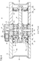
FIG. 4 is a cross-sectional view taken along line IV-IV ofFIG. 1 ; -
FIG. 5 is a perspective view in which an upper side portion of the pressure booster shown inFIG. 1 is illustrated in cutaway; -
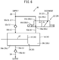
FIG. 6 is a configuration diagram of a first solenoid valve and a second solenoid valve; -
FIG. 7 is a schematic cross-sectional view showing principles of operation of the pressure booster ofFIG. 1 ; and -
FIG. 8 is a schematic cross-sectional view showing principles of operation of the pressure booster ofFIG. 1 . - A preferred embodiment of a pressure booster according to the present invention will be described in detail below with reference to the drawings.
- As shown in
FIGS. 1 to 5 , apressure booster 10 according to the present embodiment includes a tandem type cylinder structure in which afirst cylinder 14 is disposed contiguously on one end side (a side in the A1 direction) of acenter body 12, and asecond cylinder 16 is disposed contiguously on another end side (a side in the A2 direction) of thecenter body 12. Accordingly, in thepressure booster 10, thefirst cylinder 14, thecenter body 12, and thesecond cylinder 16 are disposed contiguously in this order from the A1 direction toward the A2 direction. Moreover, the outer peripheral surfaces of thefirst cylinder 14, thecenter body 12, and thesecond cylinder 16 are formed substantially flush with each other. - A block-
shaped control unit 18 is disposed on an upper surface of thecenter body 12. In thecontrol unit 18, aconnector 20 is disposed on a side surface in the A1 direction. Theconnector 20 is connected to afirst solenoid valve 22 and asecond solenoid valve 24 in thecontrol unit 18, and on the other hand, is capable of being connected to a PLC (Programmable Logic Controller) 26, which is a higher order control device with respect to thepressure booster 10. - In the
control unit 18, on a side surface thereof in the A2 direction, aninlet port 28 is provided that receives a supply of fluid (for example, air) from a non-illustrated external fluid supply source, and on both sides sandwiching theinlet port 28 therebetween, afirst discharge port 30 and asecond discharge port 32 are provided. - As shown in
FIGS. 2 to 4 , afirst chamber 34 is formed inside thefirst cylinder 14, whereas asecond chamber 36 is formed inside thesecond cylinder 16. In this case, afirst cover member 38 is fixed to an end of thefirst cylinder 14 in the A1 direction, and thecenter body 12 is disposed at an end in the A2 direction, thereby forming thefirst chamber 34. On the other hand, thecenter body 12 is disposed at an end in the A1 direction of thesecond cylinder 16, and asecond cover member 40 is fixed to an end in the A2 direction, thereby forming thesecond chamber 36. - Additionally, in the interior of the
pressure booster 10, apiston rod 42 penetrates through thecenter body 12 in the A directions, and extends to thefirst chamber 34 and thesecond chamber 36. In thefirst chamber 34, afirst piston 44 is connected to one end of thepiston rod 42 in the A1 direction. Consequently, thefirst chamber 34 is partitioned into a firstpressure boosting chamber 34a on a side in the A2 direction, and afirst drive chamber 34b on a side in the A1 direction. On the other hand, in thesecond chamber 36, asecond piston 46 is connected to another end of thepiston rod 42 in the A2 direction. Consequently, thesecond chamber 36 is partitioned into a secondpressure boosting chamber 36a on a side in the A1 direction, and asecond drive chamber 36b on a side in the A2 direction. Moreover, thefirst piston 44 is displaced inside thefirst chamber 34 in the A directions without coming into contact with thecenter body 12 and thefirst cover member 38. Further, thesecond piston 46 is displaced inside thesecond chamber 36 in the A directions without coming into contact with thecenter body 12 and thesecond cover member 40. - In the
aforementioned control unit 18 and thecenter body 12, afluid supplying mechanism 48 is provided, which communicates with theinlet port 28, and supplies the fluid that is supplied from the fluid supply source through theinlet port 28 to at least one from among the firstpressure boosting chamber 34a and the secondpressure boosting chamber 36a. - The
fluid supplying mechanism 48 includes aninlet flow passage 50a that communicates with theinlet port 28 and extends downwardly from the upper surface of thecenter body 12, a firstsupply flow passage 50b through which theinlet flow passage 50a and the firstpressure boosting chamber 34a communicate with each other, and a secondsupply flow passage 50c through which theinlet flow passage 50a and the secondpressure boosting chamber 36a communicate with each other. - A first
inlet check valve 52a, which permits the supply of fluid from theinlet port 28 to the firstpressure boosting chamber 34a, while preventing back-flowing of the fluid from the firstpressure boosting chamber 34a, is provided in the firstsupply flow passage 50b. Further, a secondinlet check valve 52b, which permits the supply of fluid from theinlet port 28 to the secondpressure boosting chamber 36a, while preventing back-flowing of the fluid from the secondpressure boosting chamber 36a, is provided in the secondsupply flow passage 50c. - An
output port 54, which outputs to the exterior the fluid that has been boosted in pressure in accordance with a later-described pressure boosting operation by thepressure booster 10, is formed on the front surface of thecenter body 12. Further, afluid output mechanism 56, which communicates with theoutput port 54, and outputs to the exterior via theoutput port 54 the fluid that has been boosted in pressure in the firstpressure boosting chamber 34a or the secondpressure boosting chamber 36a, is provided in thecenter body 12. - The
fluid output mechanism 56 is provided on a lower side portion of thepiston rod 42 in thecenter body 12. Thefluid output mechanism 56 includes a firstoutput flow passage 58a through which theoutput port 54 and the firstpressure boosting chamber 34a communicate with each other, and a secondoutput flow passage 58b through which theoutput port 54 and the secondpressure boosting chamber 36a communicate with each other. - A first
outlet check valve 60a, which permits output of the fluid after having been boosted in pressure, from the firstpressure boosting chamber 34a to theoutput port 54, while preventing back-flowing of the fluid into the firstpressure boosting chamber 34a, is provided in the firstoutput flow passage 58a. Further, a secondoutlet check valve 60b, which permits output of the fluid after having been boosted in pressure, from the secondpressure boosting chamber 36a to theoutput port 54, while preventing back-flowing of the fluid into the secondpressure boosting chamber 36a, is provided in the secondoutput flow passage 58b. - As shown in
FIGS. 5 and6 , thefluid supplying mechanism 48 further includes a firstdrive flow passage 62a communicating with thefirst drive chamber 34b, and a seconddrive flow passage 62b communicating with thesecond drive chamber 36b. The firstdrive flow passage 62a is a flow passage that interconnects thefirst drive chamber 34b and aconnection port 64a of thefirst solenoid valve 22, and extends in the A directions in upper side portions inside thefirst cylinder 14 and thecenter body 12. One end of the firstdrive flow passage 62a communicates with thefirst drive chamber 34b, and the other end thereof communicates with theconnection port 64a of thefirst solenoid valve 22 inside thecontrol unit 18. On the other hand, the seconddrive flow passage 62b is a flow passage that interconnects thesecond drive chamber 36b and aconnection port 66a of thesecond solenoid valve 24, and extends in the A directions in upper side portions inside thesecond cylinder 16 and thecenter body 12. One end of the seconddrive flow passage 62b communicates with thesecond drive chamber 36b, and the other end thereof communicates with theconnection port 66a of thesecond solenoid valve 24 inside thecontrol unit 18. - Each of the
first solenoid valve 22 and thesecond solenoid valve 24 is a single-acting two-position three-port solenoid valve. More specifically, thefirst solenoid valve 22 includes theconnection port 64a, which is connected to thefirst drive chamber 34b via the firstdrive flow passage 62a, asupply port 64b, adischarge port 64c, and asolenoid 64d. On the other hand, thesecond solenoid valve 24 includes theconnection port 66a, which is connected to thesecond drive chamber 36b via the seconddrive flow passage 62b, asupply port 66b, adischarge port 66c, and asolenoid 66d. - In this instance, in the case that control signals are supplied from the
PLC 26 to thesolenoid 64d through theconnector 20, while on the other hand, control signals are not supplied with respect to thesolenoid 66d (supply of the control signals is halted), thesupply port 64b of thefirst solenoid valve 22 and theconnection port 64a are connected, together with thedischarge port 66c of thesecond solenoid valve 24 and theconnection port 66a being connected. Consequently, fluid is supplied from theinlet port 28 to thefirst drive chamber 34b via the firstdrive flow passage 62a, whereas the fluid inside thesecond drive chamber 36b is discharged to the exterior through the seconddrive flow passage 62b and thesecond discharge port 32. As a result, thefirst piston 44, thepiston rod 42, and thesecond piston 46 are displaced toward thesecond drive chamber 36b (in the direction A2) by the pressure of the fluid supplied to thefirst drive chamber 34b. - On the other hand, in the case that supply of control signals from the
PLC 26 to thesolenoid 64d is stopped, while on the other hand, control signals are supplied to thesolenoid 66d through theconnector 20, thedischarge port 64c of thefirst solenoid valve 22 and theconnection port 64a are connected, together with thesupply port 66b of thesecond solenoid valve 24 and theconnection port 66a being connected. Consequently, the fluid inside thefirst drive chamber 34b is discharged to the exterior through the firstdrive flow passage 62a and thefirst discharge port 30, whereas the fluid is supplied to thesecond drive chamber 36b from theinlet port 28 via the seconddrive flow passage 62b. As a result, thefirst piston 44, thepiston rod 42, and thesecond piston 46 are displaced toward thefirst drive chamber 34b (in the direction A1) by the pressure of the fluid supplied to thesecond drive chamber 36b. - As shown in
FIGS. 1 to 3 and5 , twogrooves 68 that extend in the A directions are formed above and below on each of side surfaces (a front surface on the side of theoutput port 54, and a rear surface) of each of thefirst cylinder 14 and thesecond cylinder 16. A firstposition detecting sensor 70a and a secondposition detecting sensor 70b are embedded respectively in the twogrooves 68 formed on the front surface of thefirst cylinder 14. Further, as shown inFIG. 4 , an annularpermanent magnet 72 is embedded in an outer circumferential surface of thefirst piston 44. - The first
position detecting sensor 70a is a magnetic sensor, which detects the magnetism of thepermanent magnet 72 when thefirst piston 44 is displaced to a location (one end side of the first chamber 34) in the vicinity of thecenter body 12 inside thefirst chamber 34, and outputs a detection signal thereof to thePLC 26. The secondposition detecting sensor 70b is a magnetic sensor, which detects the magnetism of thepermanent magnet 72 when thefirst piston 44 is displaced to a location (another end side of the first chamber 34) in the vicinity of thefirst cover member 38 inside thefirst chamber 34, and outputs a detection signal thereof to thePLC 26. More specifically, the firstposition detecting sensor 70a and the secondposition detecting sensor 70b detect the position of thefirst piston 44 by detecting the magnetism produced by thepermanent magnet 72. On the basis of the detection signals from the firstposition detecting sensor 70a and the secondposition detecting sensor 70b, thePLC 26 outputs to theconnector 20 control signals in order to excite thesolenoid 64d or thesolenoid 66d. - Operations of the
pressure booster 10, which is configured in the manner described above, will be described with reference toFIGS. 7 and8 . In providing such operational descriptions, reference will also be made toFIGS. 1 through 6 as necessary. Moreover, in order to facilitate the description, inFIGS. 7 and8 , it should be noted that the cross-sectional shape of thepressure booster 10 is illustrated schematically and in a deformed manner. - In this instance, a description will be given of a case in which, by causing the
first piston 44 and thesecond piston 46 to be displaced alternately in the A1 direction and the A2 direction, the fluid (for example, air) which is supplied to the firstpressure boosting chamber 34a and the secondpressure boosting chamber 36a is alternately boosted in pressure and output to the exterior. - At first, with reference to
FIG. 7 , a case will be described in which the fluid supplied to the secondpressure boosting chamber 36a is boosted in pressure by causing thefirst piston 44 and thesecond piston 46 to be displaced in the A1 direction. - In this case, for example, the
first piston 44 is positioned inside thefirst chamber 34 and is separated by a slight gap from thecenter body 12, and thesecond piston 46 is positioned inside thesecond chamber 36 and is separated by a slight gap from thesecond cover member 40. - The fluid supplied from the external fluid supply source is supplied from the
inlet port 28 to thefluid supplying mechanism 48. Thefluid supplying mechanism 48 supplies the fluid to the firstpressure boosting chamber 34a via the firstsupply flow passage 50b. It should be noted that, in the secondpressure boosting chamber 36a, fluid is already filled therein by a previous operation. - In this instance, the first
position detecting sensor 70a detects the magnetism produced by thepermanent magnet 72 that is mounted on thefirst piston 44, and outputs a detection signal thereof to thePLC 26. On the basis of the detection signal from the firstposition detecting sensor 70a, thePLC 26 outputs a control signal to theconnector 20 in order to excite thesolenoid 66d of thesecond solenoid valve 24. Consequently, the control signal is input to thecontrol unit 18 via theconnector 20. - The
solenoid 66d of thesecond solenoid valve 24 is excited due to the supply of the control signal (first position), and thesecond drive chamber 36b communicates with theinlet port 28 via the seconddrive flow passage 62b, theconnection port 66a, and thesupply port 66b. Consequently, the fluid from the fluid supply source is supplied to thesecond drive chamber 36b via the seconddrive flow passage 62b, etc. Due to the fluid supplied to thesecond drive chamber 36b, a pressing force directed toward thefirst drive chamber 34b (in the direction A1) acts on thesecond piston 46. - On the other hand, since a control signal is not supplied with respect to the
solenoid 64d of thefirst solenoid valve 22, thesolenoid 64d is placed in a demagnetized state (second position). Consequently, thefirst drive chamber 34b is connected to thefirst discharge port 30 via the firstdrive flow passage 62a, theconnection port 64a, and thedischarge port 64c, and the fluid inside thefirst drive chamber 34b is discharged to the exterior. As a result, due to the fluid supplied to the firstpressure boosting chamber 34a, the pressing force directed toward thefirst drive chamber 34b (in the direction A1) acts on thefirst piston 44. - In this manner, in the example of
FIG. 7 , fluid is supplied to the firstpressure boosting chamber 34a, fluid is supplied to thesecond drive chamber 36b, and the fluid inside thefirst drive chamber 34b is discharged. Consequently, by the fluid supplied to the firstpressure boosting chamber 34a and thesecond drive chamber 36b, thefirst piston 44 and thesecond piston 46 respectively receive pressing forces in the A1 direction. As a result, thefirst piston 44, thepiston rod 42, and thesecond piston 46 are integrally displaced in the A1 direction as shown inFIG. 7 . - Consequently, the fluid inside the second
pressure boosting chamber 36a is compressed due to the displacement of thesecond piston 46 in the A1 direction, and the pressure value thereof is increased (boosted in pressure). In the secondpressure boosting chamber 36a, it is possible to increase the pressure of the supplied fluid up to a pressure value that is two times that of the original pressure at a maximum. The fluid after having been boosted in pressure is output to the exterior through the secondoutput flow passage 58b and theoutput port 54 of thefluid output mechanism 56. - In the case that the
permanent magnet 72 is moved away from a detectable range of the firstposition detecting sensor 70a due to the movement of thefirst piston 44, thepiston rod 42, and thesecond piston 46 in the A1 direction, the firstposition detecting sensor 70a stops outputting the detection signal with respect to thePLC 26. Thereafter, by thefirst piston 44 arriving at a position in the vicinity of the first cover member 38 (a position separated by a slight gap from the first cover member 38), movement of thefirst piston 44, thepiston rod 42, and thesecond piston 46 in the A1 direction is stopped. - Next, with reference to
FIG. 8 , a case will be described in which the fluid supplied to the firstpressure boosting chamber 34a is boosted in pressure by causing thefirst piston 44, thepiston rod 42, and thesecond piston 46 to be displaced in the A2 direction. - Initially, the
fluid supplying mechanism 48 supplies the fluid to the secondpressure boosting chamber 36a via the secondsupply flow passage 50c. Moreover, by the previous operation shown inFIG. 7 , fluid is already filled in the firstpressure boosting chamber 34a. Further, the secondposition detecting sensor 70b detects the magnetism produced by thepermanent magnet 72, and outputs a detection signal thereof to thePLC 26. On the basis of the detection signal from the secondposition detecting sensor 70b, with respect to theconnector 20, thePLC 26 stops outputting the control signal with respect to thesolenoid 66d of thesecond solenoid valve 24, while on the other hand, starts outputting a control signal with respect to thesolenoid 64d of thefirst solenoid valve 22. Consequently, the control signal is input to thecontrol unit 18 via theconnector 20 in order to excite thesolenoid 64d. - Therefore, the
solenoid 64d of thefirst solenoid valve 22 is excited due to the supply of the control signal (first position), and thefirst drive chamber 34b communicates with theinlet port 28 via the firstdrive flow passage 62a, theconnection port 64a, and thesupply port 64b. Consequently, the fluid from the fluid supply source is supplied to thefirst drive chamber 34b via the firstdrive flow passage 62a, etc. Due to the fluid supplied to thefirst drive chamber 34b, a pressing force directed toward thesecond drive chamber 36b (in the direction A2) acts on thefirst piston 44. - On the other hand, since supply of the control signal is stopped with respect to the
solenoid 66d of thesecond solenoid valve 24, thesolenoid 66d is placed in a demagnetized state (second position). Consequently, thesecond drive chamber 36b is connected to thesecond discharge port 32 via the seconddrive flow passage 62b, theconnection port 66a, and thedischarge port 66c, and the fluid inside thesecond drive chamber 36b is discharged to the exterior. As a result, due to the fluid supplied to the secondpressure boosting chamber 36a, the pressing force directed toward thesecond drive chamber 36b (in the direction A2) acts on thesecond piston 46. - Accordingly, in the example of
FIG. 8 , fluid is supplied to the secondpressure boosting chamber 36a, fluid is supplied to thefirst drive chamber 34b, and the fluid inside thesecond drive chamber 36b is discharged. Consequently, by the fluid supplied to thefirst drive chamber 34b and the secondpressure boosting chamber 36a, thefirst piston 44 and thesecond piston 46 respectively receive pressing forces in the A2 direction. As a result, thefirst piston 44, thepiston rod 42, and thesecond piston 46 are integrally displaced in the A2 direction as shown inFIG. 8 . - Consequently, the fluid inside the first
pressure boosting chamber 34a is compressed due to the displacement of thefirst piston 44 in the A2 direction, and the pressure value thereof is increased (boosted in pressure). In the firstpressure boosting chamber 34a as well, it is possible to increase the pressure of the supplied fluid up to a pressure value that is two times that of the original pressure at a maximum, and the fluid after having been boosted in pressure is output to the exterior through the firstoutput flow passage 58a and theoutput port 54 of thefluid output mechanism 56. - In the case that the
permanent magnet 72 is moved away from a detectable range of the secondposition detecting sensor 70b due to the movement of thefirst piston 44, thepiston rod 42, and thesecond piston 46 in the A2 direction, the secondposition detecting sensor 70b stops outputting the detection signal to thePLC 26. Thereafter, by thesecond piston 46 arriving at a position in the vicinity of the second cover member 40 (a position separated by a slight gap from the second cover member 40), movement of thefirst piston 44, thepiston rod 42, and thesecond piston 46 in the A2 direction is stopped. - In addition, with the
pressure booster 10 according to the present embodiment, the pressure boosting operations shown inFIGS. 7 and8 are carried out alternately by causing thefirst piston 44, thepiston rod 42, and thesecond piston 46 to undergo reciprocal movement in the A1 direction and the A2 direction. Consequently, in thepressure booster 10, the pressure value of the fluid supplied from the external fluid supply source can be boosted in pressure up to a pressure value that is two times that of the original pressure at a maximum, and the fluid after having been boosted in pressure can be output to the exterior through theoutput port 54, alternately from the firstpressure boosting chamber 34a and the secondpressure boosting chamber 36a. - Moreover, the fluid after having been boosted in pressure which is output from the
pressure booster 10 is stored in a non-illustrated external tank. As a result, it is possible for the fluid after having been boosted in pressure to be supplied to any arbitrary fluid pressure device. - As has been described above, in accordance with the
pressure booster 10 according to the present embodiment, instead of a conventional drive mechanism for driving the pistons by a mechanical mechanism, thefirst piston 44, thepiston rod 42, and thesecond piston 46 are driven in the A1 direction and the A2 direction by electrically controlling the movement direction on the basis of the detection result of the firstposition detecting sensor 70a and the secondposition detecting sensor 70b. Consequently, the drive mechanism of thefirst piston 44, thepiston rod 42, and thesecond piston 46 can be simplified, and the internal structure of thepressure booster 10 can be made in a simple and straightforward manner. - Further, in the
pressure booster 10, a control is performed only to supply the fluid to at least one from among the firstpressure boosting chamber 34a and the secondpressure boosting chamber 36a, and to supply or discharge the fluid with respect to thefirst drive chamber 34b and thesecond drive chamber 36b. Accordingly, in thepressure booster 10, there is no need for a regulator, and a pressure value (set value) of the fluid after having been boosted in pressure is fixed. As a result, in comparison with a conventional pressure booster equipped with a regulator, the external dimensions of thepressure booster 10 can be reduced, and thepressure booster 10 can be made compact. - Further, conventionally, operations of supplying and discharging the fluid are switched, as a result of knock pins being incorporated in the pressure booster, and the pistons being caused to abut against the knock pins. However, there is a problem in that sounds (hammering noises) which occur each time that the pistons move and abut against the knock pins produce noise, and the sounds (operating sounds) generated by the pressure booster during operation of the pistons is large.
- In contrast thereto, with the
pressure booster 10 according to the present embodiment, as described above, since the operations of supplying and discharging the fluid are switched on the basis of the detection results of the firstposition detecting sensor 70a and the secondposition detecting sensor 70b, the aforementioned knock pins are rendered unnecessary. As a result, noises generated upon movement of thefirst piston 44 and thesecond piston 46 can be suppressed, and operating sounds of thepressure booster 10 can be reduced. - Further, by using the
first solenoid valve 22 and thesecond solenoid valve 24, switching of the direction of movement of thefirst piston 44, thepiston rod 42, and thesecond piston 46 is carried out electrically, and thus the internal structure of thepressure booster 10 can be further simplified. - Moreover, as has been described above, since the conventional pressure booster subjects the pistons to reciprocal motion by way of a mechanical mechanism, it is difficult to grasp from the exterior the number of times (how many times) that such reciprocal motion has been performed. In contrast thereto, with the
pressure booster 10 according to the present embodiment, since the position of thefirst piston 44 can be easily detected by the firstposition detecting sensor 70a and the secondposition detecting sensor 70b, the number of times that thefirst piston 44, thepiston rod 42, and thesecond piston 46 undergo reciprocating motion can be grasped by thePLC 26. Further, thepressure booster 10 can be suitably utilized, for example, in order to supply a pressure fluid to various fluid pressure devices in a production line of a factory. More specifically, this is because, in a factory, power supply lines are disposed at various locations, and the power supply for the firstposition detecting sensor 70a, the secondposition detecting sensor 70b, thefirst solenoid valve 22, and thesecond solenoid valve 24 can be easily secured. - Further, by the
fluid supplying mechanism 48 being equipped with the firstinlet check valve 52a and the secondinlet check valve 52b, and by thefluid output mechanism 56 being equipped with the firstoutlet check valve 60a and the secondoutlet check valve 60b, in the firstpressure boosting chamber 34a and the secondpressure boosting chamber 36a, the pressure of the fluid can be reliably increased. - Further, by utilizing the first
position detecting sensor 70a and the secondposition detecting sensor 70b, since it is easy to detect the position of thefirst piston 44, the internal structure of thepressure booster 10 can be further simplified, and it is possible to enhance the productivity of thepressure booster 10. - In addition, the first
position detecting sensor 70a and the secondposition detecting sensor 70b are magnetic sensors that detect the position of thefirst piston 44 by detecting the magnetism produced by thepermanent magnet 72 attached to thefirst piston 44, and therefore, it is possible to easily and accurately detect the position of thefirst piston 44. - In the above description, although a case has been described in which the first
position detecting sensor 70a and the secondposition detecting sensor 70b detect the position of thefirst piston 44, it is a matter of course that the same effects can be obtained even in the case that the firstposition detecting sensor 70a and the secondposition detecting sensor 70b are embedded in thegrooves 68 of thesecond cylinder 16, thepermanent magnet 72 is attached to thesecond piston 46, and the position of thesecond piston 46 is detected by the firstposition detecting sensor 70a and the secondposition detecting sensor 70b. - Further, in the
pressure booster 10, thecenter body 12 is interposed between thefirst chamber 34 and thesecond chamber 36, thefirst cover member 38 is disposed at an end of thefirst chamber 34 in the A1 direction remote from thecenter body 12, and thesecond cover member 40 is disposed at an end of thesecond chamber 36 in the A2 direction remote from thecenter body 12. In this case, thefirst piston 44 is displaced inside thefirst chamber 34 without coming into contact with thecenter body 12 and thefirst cover member 38, and thesecond piston 46 is displaced inside thesecond chamber 36 without coming into contact with thecenter body 12 and thesecond cover member 40. In accordance with this feature, thefirst piston 44 and thesecond piston 46 are capable of being moved smoothly when the fluid is supplied to or discharged from the firstpressure boosting chamber 34a, the secondpressure boosting chamber 36a, thefirst drive chamber 34b, and thesecond drive chamber 36b. - The present invention is not limited to the embodiments described above, and it is a matter of course that various modified or additional structures could be adopted therein without deviating from the essence and gist of the present invention as set forth in the appended claims.
Claims (7)
- A pressure booster (10), comprising:a first chamber (34);a second chamber (36) adjacent to the first chamber (34);a piston rod (42) extending to the first chamber (34) and the second chamber (36);a first piston (44) which, by being connected to one end of the piston rod (42) inside the first chamber (34), is configured to partition the first chamber (34) into a first pressure boosting chamber (34a) on a side of the second chamber (36), and a first drive chamber (34b) remote from the second chamber (36);a second piston (46) which, by being connected to another end of the piston rod (42) inside the second chamber (36), is configured to partition the second chamber (36) into a second pressure boosting chamber (36a) on a side of the first chamber (34), and a second drive chamber (36b) remote from the first chamber (34);a position detecting sensor (70a, 70b) configured to detect a position of the first piston (44) or the second piston (46); anda fluid supplying mechanism (48) configured to supply fluid to at least one of the first pressure boosting chamber (34a) and the second pressure boosting chamber (36a), together with executing, based on a detection result of the position detecting sensor (70a, 70b), switching between an operation of supplying the fluid to the first drive chamber (34b) and discharging the fluid from the second drive chamber (36b), and an operation of discharging the fluid from the first drive chamber (34b) and supplying the fluid to the second drive chamber (36b).
- The pressure booster (10) according to claim 1, wherein the fluid supplying mechanism (48) comprises:a first supply flow passage (50b) configured to supply the fluid supplied from exterior into the first pressure boosting chamber (34a);a second supply flow passage (50c) configured to supply the fluid supplied from the exterior into the second pressure boosting chamber (36a);a first solenoid valve (22) configured to supply the fluid supplied from the exterior into the first drive chamber (34b), or to discharge the fluid inside the first drive chamber (34b) to the exterior, based on a detection result of the position detecting sensor (70a, 70b); anda second solenoid valve (24) configured to supply the fluid supplied from the exterior into the second drive chamber (36b), or to discharge the fluid inside the second drive chamber (36b) to the exterior, based on the detection result of the position detecting sensor (70a, 70b).
- The pressure booster (10) according to claim 2, wherein the fluid supplying mechanism (48) further comprises:a first inlet check valve (52a) provided in the first supply flow passage (50b) and configured to prevent back-flowing of the fluid from the first pressure boosting chamber (34a); anda second inlet check valve (52b) provided in the second supply flow passage (50c) and configured to prevent back-flowing of the fluid from the second pressure boosting chamber (36a).
- The pressure booster (10) according to claim 1, further comprising:a fluid output mechanism (56) configured to output to an exterior the fluid which was boosted in pressure in the first pressure boosting chamber (34a) or the second pressure boosting chamber (36a);wherein the fluid output mechanism (56) is configured to include a first outlet check valve (60a) configured to prevent back-flowing of the fluid into the first pressure boosting chamber (34a), and a second outlet check valve (60b) configured to prevent back-flowing of the fluid into the second pressure boosting chamber (36a).
- The pressure booster (10) according to claim 1, wherein the position detecting sensor (70a, 70b) comprises a first position detecting sensor (70a) configured to detect arrival of the first piston (44) or the second piston (46) at one end side of the first chamber (34) or the second chamber (36), and a second position detecting sensor (70b) configured to detect arrival of the first piston (44) or the second piston (46) at another end side of the first chamber (34) or the second chamber (36).
- The pressure booster (10) according to claim 1, wherein the position detecting sensor (70a, 70b) comprises a magnetic sensor configured to detect the position of the first piston (44) or the second piston (46) by detecting magnetism produced by a magnet (72) attached to the first piston (44) or the second piston (46).
- The pressure booster (10) according to claim 1, wherein:a center body (12) is interposed between the first chamber (34) and the second chamber (36);a first cover member (38) is disposed at an end of the first drive chamber (34b) remote from the center body (12);a second cover member (40) is disposed at an end of the second drive chamber (36b) remote from the center body (12);the first piston (44) is displaced inside the first chamber (34) without coming into contact with the center body (12) and the first cover member (38); andthe second piston (46) is displaced inside the second chamber (36) without coming into contact with the center body (12) and the second cover member (40).
Applications Claiming Priority (2)
| Application Number | Priority Date | Filing Date | Title |
|---|---|---|---|
| JP2016226430A JP2018084260A (en) | 2016-11-22 | 2016-11-22 | Booster |
| PCT/JP2017/029505 WO2018096738A1 (en) | 2016-11-22 | 2017-08-17 | Pressure booster |
Publications (2)
| Publication Number | Publication Date |
|---|---|
| EP3546762A1 true EP3546762A1 (en) | 2019-10-02 |
| EP3546762A4 EP3546762A4 (en) | 2020-07-29 |
Family
ID=62194877
Family Applications (1)
| Application Number | Title | Priority Date | Filing Date |
|---|---|---|---|
| EP17874513.9A Pending EP3546762A4 (en) | 2016-11-22 | 2017-08-17 | PRESSURE AMPLIFIERS |
Country Status (10)
| Country | Link |
|---|---|
| US (1) | US20210293258A1 (en) |
| EP (1) | EP3546762A4 (en) |
| JP (1) | JP2018084260A (en) |
| KR (1) | KR102266450B1 (en) |
| CN (1) | CN109983238B (en) |
| BR (1) | BR112019010392A2 (en) |
| MX (1) | MX2019005899A (en) |
| RU (1) | RU2731871C9 (en) |
| TW (1) | TWI639776B (en) |
| WO (1) | WO2018096738A1 (en) |
Cited By (2)
| Publication number | Priority date | Publication date | Assignee | Title |
|---|---|---|---|---|
| IT202100006623A1 (en) * | 2021-03-19 | 2022-09-19 | Scm Group Spa | AIR/AIR TYPE PRESSURE MULTIPLIER. |
| IT202100014633A1 (en) * | 2021-06-04 | 2022-12-04 | Camozzi Automation S P A | PRESSURE MULTIPLIER |
Families Citing this family (2)
| Publication number | Priority date | Publication date | Assignee | Title |
|---|---|---|---|---|
| JP7137162B2 (en) * | 2019-10-29 | 2022-09-14 | Smc株式会社 | hydraulic cylinder |
| EP4617507A3 (en) * | 2021-03-31 | 2025-11-12 | Eagle Industry Co., Ltd. | Fluid circuit |
Family Cites Families (26)
| Publication number | Priority date | Publication date | Assignee | Title |
|---|---|---|---|---|
| JPS58193101U (en) * | 1982-06-18 | 1983-12-22 | エスエムシ−株式会社 | Boosting air supply device |
| JPH0522641Y2 (en) * | 1986-03-11 | 1993-06-10 | ||
| JPH0231589Y2 (en) * | 1986-09-19 | 1990-08-27 | ||
| JPS63243502A (en) * | 1987-03-27 | 1988-10-11 | Konan Denki Kk | Air booster |
| RU2037673C1 (en) * | 1991-06-10 | 1995-06-19 | Анатолий Панкратьевич Макаров | Source of the liquid high pressure |
| JP2535452Y2 (en) | 1992-03-13 | 1997-05-14 | エスエムシー株式会社 | Pressure booster |
| JPH0648974U (en) * | 1992-12-16 | 1994-07-05 | 小原株式会社 | Shock absorber in pressurizing cylinder for welding machine |
| JP3911643B2 (en) * | 1995-07-05 | 2007-05-09 | 富士通株式会社 | Method for forming buried conductive layer |
| JP2955220B2 (en) | 1995-12-06 | 1999-10-04 | 太陽鉄工株式会社 | In-line pressure booster |
| JPH09229007A (en) * | 1996-02-28 | 1997-09-02 | Izumi Prod Co | Cylinder device of pressure intensified type |
| JPH10267002A (en) | 1997-03-25 | 1998-10-06 | Smc Corp | Pressure booster |
| JP3792000B2 (en) | 1997-03-25 | 2006-06-28 | Smc株式会社 | Nitrogen gas booster |
| DE29818762U1 (en) * | 1998-10-21 | 1998-12-24 | Festo AG & Co, 73734 Esslingen | Fluid operated working device |
| JP3705730B2 (en) | 2000-04-28 | 2005-10-12 | Smc株式会社 | Pneumatic cylinder exhaust recovery device |
| JP3568883B2 (en) | 2000-07-19 | 2004-09-22 | Smc株式会社 | Pressure booster |
| DE20100122U1 (en) * | 2001-01-05 | 2001-06-21 | Reiplinger, Günter, 54669 Bollendorf | Pressure translator |
| RU2258840C1 (en) * | 2003-12-16 | 2005-08-20 | Республиканское унитарное предприятие "Минский тракторный завод" | Pneumohydraulic booster |
| DE202006002145U1 (en) * | 2006-02-10 | 2006-04-27 | Festo Ag & Co | Compressed air maintenance device |
| JP4739980B2 (en) * | 2006-02-21 | 2011-08-03 | シーケーディ株式会社 | Position detector for fluid pressure cylinder |
| JP4301310B2 (en) * | 2007-03-12 | 2009-07-22 | Smc株式会社 | Booster |
| RU2415309C1 (en) * | 2009-11-18 | 2011-03-27 | Открытое Акционерное Общество "ЭНИМС" | Hydro-driven power unit for installations of water-jet cutting |
| US9695840B2 (en) * | 2013-08-20 | 2017-07-04 | Vianney Rabhi | Reversible hydraulic pressure converter employing tubular valves |
| CN204458579U (en) * | 2015-02-06 | 2015-07-08 | 内蒙古包钢钢联股份有限公司 | A kind of supercharging oil supply loop device |
| CN205578403U (en) * | 2016-04-19 | 2016-09-14 | 湖南协力液压有限公司 | Butter type hydraulic oil cylinder |
| CN205639162U (en) * | 2016-05-30 | 2016-10-12 | 龙岩市山力工程液压有限公司 | Oil cylinder |
| CN106015130B (en) * | 2016-07-06 | 2018-01-23 | 天津优瑞纳斯液压机械有限公司 | High thrust high speed hydraulic cylinder and its method of work |
-
2016
- 2016-11-22 JP JP2016226430A patent/JP2018084260A/en active Pending
-
2017
- 2017-08-17 BR BR112019010392A patent/BR112019010392A2/en not_active Application Discontinuation
- 2017-08-17 RU RU2019119403A patent/RU2731871C9/en active
- 2017-08-17 MX MX2019005899A patent/MX2019005899A/en unknown
- 2017-08-17 CN CN201780072177.4A patent/CN109983238B/en active Active
- 2017-08-17 WO PCT/JP2017/029505 patent/WO2018096738A1/en not_active Ceased
- 2017-08-17 EP EP17874513.9A patent/EP3546762A4/en active Pending
- 2017-08-17 KR KR1020197018041A patent/KR102266450B1/en active Active
- 2017-08-17 US US16/462,623 patent/US20210293258A1/en not_active Abandoned
- 2017-09-05 TW TW106130290A patent/TWI639776B/en not_active IP Right Cessation
Cited By (4)
| Publication number | Priority date | Publication date | Assignee | Title |
|---|---|---|---|---|
| IT202100006623A1 (en) * | 2021-03-19 | 2022-09-19 | Scm Group Spa | AIR/AIR TYPE PRESSURE MULTIPLIER. |
| IT202100014633A1 (en) * | 2021-06-04 | 2022-12-04 | Camozzi Automation S P A | PRESSURE MULTIPLIER |
| WO2022254262A1 (en) * | 2021-06-04 | 2022-12-08 | Camozzi Automation S.p.A. | Pressure multiplier |
| US12590593B2 (en) | 2021-06-04 | 2026-03-31 | Camozzi Automation S.p.A. | Pressure multiplier |
Also Published As
| Publication number | Publication date |
|---|---|
| CN109983238A (en) | 2019-07-05 |
| JP2018084260A (en) | 2018-05-31 |
| TWI639776B (en) | 2018-11-01 |
| EP3546762A4 (en) | 2020-07-29 |
| TW201819776A (en) | 2018-06-01 |
| MX2019005899A (en) | 2019-08-26 |
| US20210293258A1 (en) | 2021-09-23 |
| RU2731871C9 (en) | 2021-06-25 |
| KR102266450B1 (en) | 2021-06-17 |
| KR20190085104A (en) | 2019-07-17 |
| RU2731871C1 (en) | 2020-09-08 |
| CN109983238B (en) | 2021-04-09 |
| WO2018096738A1 (en) | 2018-05-31 |
| BR112019010392A2 (en) | 2019-09-03 |
Similar Documents
| Publication | Publication Date | Title |
|---|---|---|
| US10851806B2 (en) | Pressure booster | |
| US8517475B2 (en) | Brake apparatus | |
| US20210293258A1 (en) | Pressure booster | |
| US9511758B2 (en) | Hydraulic brake system | |
| US10017168B2 (en) | Brake system | |
| EP3839265B1 (en) | Pressure booster | |
| US20120326492A1 (en) | Brake system having a pressure modulation cylinder | |
| CN110873091A (en) | Actuator motion detection device | |
| KR101567842B1 (en) | Brake device for vehicle | |
| US20210024050A1 (en) | Vehicle braking device | |
| US20150239444A1 (en) | Brake fluid pressure control actuator | |
| JP6366907B2 (en) | Fluid-controlled pressure switching valve for vehicle brake system and vehicle brake system | |
| US12590593B2 (en) | Pressure multiplier | |
| JP2011241725A (en) | Control device for piston concrete pump | |
| JPH10250544A (en) | Brake equipment | |
| KR101396862B1 (en) | Control method for hydraulic electronic control unit | |
| US20090102278A1 (en) | Pressure control device | |
| JPH03148357A (en) | Anti-locking controller |
Legal Events
| Date | Code | Title | Description |
|---|---|---|---|
| STAA | Information on the status of an ep patent application or granted ep patent |
Free format text: STATUS: THE INTERNATIONAL PUBLICATION HAS BEEN MADE |
|
| PUAI | Public reference made under article 153(3) epc to a published international application that has entered the european phase |
Free format text: ORIGINAL CODE: 0009012 |
|
| STAA | Information on the status of an ep patent application or granted ep patent |
Free format text: STATUS: REQUEST FOR EXAMINATION WAS MADE |
|
| 17P | Request for examination filed |
Effective date: 20190619 |
|
| AK | Designated contracting states |
Kind code of ref document: A1 Designated state(s): AL AT BE BG CH CY CZ DE DK EE ES FI FR GB GR HR HU IE IS IT LI LT LU LV MC MK MT NL NO PL PT RO RS SE SI SK SM TR |
|
| AX | Request for extension of the european patent |
Extension state: BA ME |
|
| DAV | Request for validation of the european patent (deleted) | ||
| DAX | Request for extension of the european patent (deleted) | ||
| A4 | Supplementary search report drawn up and despatched |
Effective date: 20200626 |
|
| RIC1 | Information provided on ipc code assigned before grant |
Ipc: F15B 3/00 20060101AFI20200622BHEP |
|
| STAA | Information on the status of an ep patent application or granted ep patent |
Free format text: STATUS: EXAMINATION IS IN PROGRESS |
|
| 17Q | First examination report despatched |
Effective date: 20230530 |
|
| RAP3 | Party data changed (applicant data changed or rights of an application transferred) |
Owner name: SMC CORPORATION |