EP3546398A1 - Conveyance device - Google Patents
Conveyance device Download PDFInfo
- Publication number
- EP3546398A1 EP3546398A1 EP18797721.0A EP18797721A EP3546398A1 EP 3546398 A1 EP3546398 A1 EP 3546398A1 EP 18797721 A EP18797721 A EP 18797721A EP 3546398 A1 EP3546398 A1 EP 3546398A1
- Authority
- EP
- European Patent Office
- Prior art keywords
- pair
- conveyance device
- electrode plate
- stopper
- conveyor
- Prior art date
- Legal status (The legal status is an assumption and is not a legal conclusion. Google has not performed a legal analysis and makes no representation as to the accuracy of the status listed.)
- Withdrawn
Links
- 230000002093 peripheral effect Effects 0.000 claims description 19
- 238000011144 upstream manufacturing Methods 0.000 claims description 17
- 239000011295 pitch Substances 0.000 description 14
- 239000007772 electrode material Substances 0.000 description 9
- 238000012986 modification Methods 0.000 description 6
- 230000004048 modification Effects 0.000 description 6
- XAGFODPZIPBFFR-UHFFFAOYSA-N aluminium Chemical compound [Al] XAGFODPZIPBFFR-UHFFFAOYSA-N 0.000 description 5
- 229910052782 aluminium Inorganic materials 0.000 description 4
- 238000000034 method Methods 0.000 description 3
- XEEYBQQBJWHFJM-UHFFFAOYSA-N Iron Chemical compound [Fe] XEEYBQQBJWHFJM-UHFFFAOYSA-N 0.000 description 2
- 238000004519 manufacturing process Methods 0.000 description 2
- 230000001105 regulatory effect Effects 0.000 description 2
- 229910000978 Pb alloy Inorganic materials 0.000 description 1
- 230000001174 ascending effect Effects 0.000 description 1
- 230000007797 corrosion Effects 0.000 description 1
- 238000005260 corrosion Methods 0.000 description 1
- 230000000694 effects Effects 0.000 description 1
- 229910052742 iron Inorganic materials 0.000 description 1
- 239000000463 material Substances 0.000 description 1
- 239000011347 resin Substances 0.000 description 1
- 229920005989 resin Polymers 0.000 description 1
- 239000010935 stainless steel Substances 0.000 description 1
- 229910001220 stainless steel Inorganic materials 0.000 description 1
Images





Classifications
-
- B—PERFORMING OPERATIONS; TRANSPORTING
- B65—CONVEYING; PACKING; STORING; HANDLING THIN OR FILAMENTARY MATERIAL
- B65G—TRANSPORT OR STORAGE DEVICES, e.g. CONVEYORS FOR LOADING OR TIPPING, SHOP CONVEYOR SYSTEMS OR PNEUMATIC TUBE CONVEYORS
- B65G57/00—Stacking of articles
- B65G57/30—Stacking of articles by adding to the bottom of the stack
- B65G57/305—Stacking of articles by adding to the bottom of the stack by means of rotary devices or endless elements
- B65G57/307—Stacking of articles by adding to the bottom of the stack by means of rotary devices or endless elements the rotary devices being screws
-
- H—ELECTRICITY
- H01—ELECTRIC ELEMENTS
- H01M—PROCESSES OR MEANS, e.g. BATTERIES, FOR THE DIRECT CONVERSION OF CHEMICAL ENERGY INTO ELECTRICAL ENERGY
- H01M10/00—Secondary cells; Manufacture thereof
- H01M10/04—Construction or manufacture in general
- H01M10/0404—Machines for assembling batteries
-
- H—ELECTRICITY
- H01—ELECTRIC ELEMENTS
- H01M—PROCESSES OR MEANS, e.g. BATTERIES, FOR THE DIRECT CONVERSION OF CHEMICAL ENERGY INTO ELECTRICAL ENERGY
- H01M4/00—Electrodes
- H01M4/02—Electrodes composed of, or comprising, active material
- H01M4/04—Processes of manufacture in general
-
- B—PERFORMING OPERATIONS; TRANSPORTING
- B65—CONVEYING; PACKING; STORING; HANDLING THIN OR FILAMENTARY MATERIAL
- B65G—TRANSPORT OR STORAGE DEVICES, e.g. CONVEYORS FOR LOADING OR TIPPING, SHOP CONVEYOR SYSTEMS OR PNEUMATIC TUBE CONVEYORS
- B65G2201/00—Indexing codes relating to handling devices, e.g. conveyors, characterised by the type of product or load being conveyed or handled
- B65G2201/02—Articles
- B65G2201/0214—Articles of special size, shape or weigh
- B65G2201/022—Flat
-
- B—PERFORMING OPERATIONS; TRANSPORTING
- B65—CONVEYING; PACKING; STORING; HANDLING THIN OR FILAMENTARY MATERIAL
- B65G—TRANSPORT OR STORAGE DEVICES, e.g. CONVEYORS FOR LOADING OR TIPPING, SHOP CONVEYOR SYSTEMS OR PNEUMATIC TUBE CONVEYORS
- B65G33/00—Screw or rotary spiral conveyors
- B65G33/02—Screw or rotary spiral conveyors for articles
- B65G33/06—Screw or rotary spiral conveyors for articles conveyed and guided by parallel screws
-
- Y—GENERAL TAGGING OF NEW TECHNOLOGICAL DEVELOPMENTS; GENERAL TAGGING OF CROSS-SECTIONAL TECHNOLOGIES SPANNING OVER SEVERAL SECTIONS OF THE IPC; TECHNICAL SUBJECTS COVERED BY FORMER USPC CROSS-REFERENCE ART COLLECTIONS [XRACs] AND DIGESTS
- Y02—TECHNOLOGIES OR APPLICATIONS FOR MITIGATION OR ADAPTATION AGAINST CLIMATE CHANGE
- Y02E—REDUCTION OF GREENHOUSE GAS [GHG] EMISSIONS, RELATED TO ENERGY GENERATION, TRANSMISSION OR DISTRIBUTION
- Y02E60/00—Enabling technologies; Technologies with a potential or indirect contribution to GHG emissions mitigation
- Y02E60/10—Energy storage using batteries
-
- Y—GENERAL TAGGING OF NEW TECHNOLOGICAL DEVELOPMENTS; GENERAL TAGGING OF CROSS-SECTIONAL TECHNOLOGIES SPANNING OVER SEVERAL SECTIONS OF THE IPC; TECHNICAL SUBJECTS COVERED BY FORMER USPC CROSS-REFERENCE ART COLLECTIONS [XRACs] AND DIGESTS
- Y02—TECHNOLOGIES OR APPLICATIONS FOR MITIGATION OR ADAPTATION AGAINST CLIMATE CHANGE
- Y02P—CLIMATE CHANGE MITIGATION TECHNOLOGIES IN THE PRODUCTION OR PROCESSING OF GOODS
- Y02P70/00—Climate change mitigation technologies in the production process for final industrial or consumer products
- Y02P70/50—Manufacturing or production processes characterised by the final manufactured product
Definitions
- An aspect of the present invention relates to a conveyance device.
- Patent Literature 1 discloses a conveyance device conveying an electrode plate for a lead storage battery. This conveyance device is provided with a pinch roller sending the electrode plate while pinching the electrode plate from above and below between front- and rear-stage unit conveyance devices. The rotation speed of the pinch roller is set so as to exceed the feed speed of the front-stage unit conveyance device. Accordingly, it is possible to quickly pass the electrode plate from the front-stage unit conveyance device to the rear-stage unit conveyance device.
- Patent Literature 1 Japanese Unexamined Patent Publication No. 2005-276555
- the electrode plate may be conveyed to an accumulator where a plurality of the electrode plates is accumulated by the conveyance device provided with the pinch roller described above.
- the electrode plate sent out by the pinch roller is dropped and accumulated at the accumulator after abutting against a backing plate.
- a fragile and shape change-prone object to be conveyed such as the electrode plate may be damaged by the impact during the drop or the abutment against the backing plate.
- An aspect of the present invention provides a conveyance device capable of suppressing damage to an object to be conveyed.
- a conveyance device includes a conveyor and a stopper.
- the conveyor conveys an object to be conveyed along a direction crossing a push-out direction of the object while pushing out the object.
- the stopper is disposed on a side where the object is pushed out with respect to the conveyor.
- the stopper abuts against the object, and prevents the object from being pushed out.
- the conveyor includes a pair of rotating bodies.
- the pair of rotating bodies includes a pair of rotating shafts and a pair of spiral parts.
- the pair of rotating bodies extends in a conveying direction of the object.
- the pair of spiral parts is spirally wound around the pair of rotating shafts.
- the pair of spiral parts is wound in directions reverse to each other.
- the pair of spiral parts supports the object in a pair of support regions between the pair of rotating shafts.
- the conveyor includes the pair of rotating bodies.
- the pair of rotating bodies includes the pair of spiral parts spirally wound around the pair of rotating shafts.
- the pair of spiral parts is wound in directions reverse to each other.
- the pair of spiral parts supports the object in the pair of support regions between the pair of rotating shafts. Accordingly, once the pair of rotating bodies rotates, the object is pushed out in a state where the object is supported by the pair of spiral parts.
- the stopper is disposed on the side where the object is pushed out. Accordingly, the object is conveyed along the stopper while abutting against the stopper in a state where the object is supported by the pair of spiral parts. As a result, damage to the object can be suppressed as compared with a case where the object is dropped without support after abutting against a backing plate.
- the conveyance device may further include a supplier.
- the supplier may supply the object to the conveyor from a side opposite to the stopper with respect to the conveyor. In this case, the object can be easily supplied to the conveyor.
- the pair of rotating bodies may rotate once from a reference rotation position each time the supplier supplies the object to the conveyor. In this case, interference between the objects can be avoided. As a result, damage to the object can be further suppressed.
- a pair of end edges on a downstream side in the conveying direction of the pair of spiral parts may be disposed outside the pair of support regions at the reference rotation position.
- the object can be sent out from the pair of spiral parts without being caught by the end edges of the pair of spiral parts on the downstream side in the conveying direction.
- the pair of spiral parts may include a pair of support surfaces supporting the object and a pair of projections provided at peripheral edge parts of the pair of support surfaces.
- the projection abuts against the object and supports the object. Accordingly, it is possible to convey the object while suppressing the friction between the object and the support surface that is attributable to the rotation of the rotating body.
- the pair of spiral parts may include a pair of support surfaces supporting the object and a pair of projections provided at peripheral edge parts of the pair of support surfaces.
- the pair of projections may be provided so as to avoid a stopper side crossing region at a pair of upstream side blades of the pair of spiral parts at a first pitch from an upstream side in the conveying direction at the reference rotation position, the stopper side crossing region being a region on the stopper side and one of regions where peripheral edge parts of the pair of support surfaces cross a trajectory for a tip side end part of the object to reach the stopper from the supplier when viewed from the conveying direction.
- the projection abuts against the object and supports the object.
- the projections being disposed such that the projections abut against the object while avoiding the damage-prone part of the object.
- the projections are provided so as to avoid a region in which it is easy to collide with the tip side end part of the object heading toward the stopper from the supplier. Accordingly, it is possible to suppress damage to the tip side end part of the object attributable to a collision with the projections.
- the pair of projections may be provided from positions that are downstream of the stopper side crossing region in the conveying direction and upstream of a rare end crossing region in the conveying direction at the pair of upstream side blades at the reference rotation position, the rare end crossing region being a region where a rear end of the object at the stopper and peripheral edge parts of the pair of support surfaces crossing each other when viewed from the conveying direction.
- the rare end crossing region being a region where a rear end of the object at the stopper and peripheral edge parts of the pair of support surfaces crossing each other when viewed from the conveying direction.
- the pair of projections may be provided up to a pair of end edges on the downstream side in the conveying direction of the pair of spiral parts. In this case, it is possible to convey the object while further suppressing the friction between the object and the support surface that is attributable to the rotation of the rotating bodies.
- the pair of spiral parts may be wound at an equal pitch with a pitch widened at an end edge on an upstream side in the conveying direction.
- the object is capable of entering the spiral from the inlet of the spiral even when the object supplied to the pair of spiral parts abuts against the stopper and jumps up due to the resultant reaction.
- radii of the pair of spiral parts may be equal to each other. In this case, rotation control with respect to the pair of spiral parts can be performed with ease.
- radii of the pair of spiral parts may be different from each other.
- the distances between the pair of rotating shafts and the stopper can be different from each other in accordance with the shape of the object.
- the stopper may have an opposing surface opposing the conveyor and a pair of guides provided on the opposing surface and extending along the conveying direction.
- the object can be guided by the pair of guides.
- the pair of guides may have a gap narrowing toward a downstream side in the conveying direction.
- the object can be positioned in the opposing direction of the pair of guides while being conveyed.
- the pair of rotating bodies may rotate such that linear velocities of peripheral edge parts of the pair of spiral parts become equal to each other.
- the pair of spiral parts is capable of pushing out the object straight toward the stopper.
- the object may be an electrode plate. In this case, damage to the electrode plate can be suppressed.
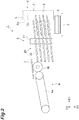
- FIG. 1 is a top view illustrating a conveyance device according to the embodiment.
- FIG. 2 is a side view illustrating the conveyance device according to the embodiment.
- a conveyance device 1 according to the embodiment illustrated in FIGS. 1 and 2 conveys an electrode plate 2 for a lead storage battery as an object to be conveyed, which is a conveyance object.
- the object by the conveyance device 1 is not limited to the electrode plate 2.
- the conveyance device 1 is applied to a process for accumulating the electrode plate 2 in a battery production line and sequentially conveys the electrode plate 2.
- the conveyed electrode plate is accumulated at an accumulator 3 and then sent to the next process.
- the electrode plate 2 is a thin plate-shaped member having a substantially rectangular shape.
- the electrode plate 2 has a pair of main surfaces opposing each other in a thickness direction.
- the electrode plate 2 includes a lead alloy-based support body, an electrode material held by the support body, and a current collector part (ear part) provided at the upper end part of the support body.
- the part between the upper and lower end parts of the support body is formed in, for example, a lattice shape by expand processing.
- the electrode material is formed by electrode material paste application to the lattice-shaped part of the support body.
- the electrode material is easily detached from the support body. Paper is attached to the surface of the electrode material so that electrode material detachment is prevented.
- the upper and lower end parts of the support body are exposed from a current collector. Accordingly, a step is formed at the upper and lower end parts of the electrode plate 2.
- the conveyance device 1 is provided with a supplier 4, a conveyor 5, and a stopper 6 arranged in this order.
- a guide 9 (described later) at the stopper 6 is not illustrated in FIG. 2 .
- the supplier 4 is disposed on the side opposite to the stopper 6 with respect to the conveyor 5.
- the supplier 4 supplies the electrode plate 2 to the conveyor 5 from the side opposite to the stopper 6 with respect to the conveyor 5.
- the supplier 4 includes a belt conveyor 4a and a rotating roller 4b.
- the belt conveyor 4a conveys the electrode plate 2 toward the conveyor 5.
- the belt conveyor 4a is disposed such that the conveying-direction downstream side end part of the belt conveyor 4a is higher than the conveying-direction upstream side end part of the belt conveyor 4a and conveys the electrode plate 2 obliquely upward.
- the rotating roller 4b is disposed between the belt conveyor 4a and the conveyor 5 and adjacent to the conveying-direction downstream side end part of the belt conveyor 4a.
- the upper surface of the rotating roller 4b is positioned on a substantially extended line of the upper surface of the belt conveyor 4a. Accordingly, the electrode plate 2 conveyed by the belt conveyor 4a smoothly transfers onto the rotating roller 4b.
- the rotating roller 4b rotates such that the upper surface side of the rotating roller 4b advances toward the conveyor 5, accelerates the electrode plate 2, and sends out the electrode plate 2 to the conveyor 5.
- the electrode plate 2 jumps out obliquely upward from the supplier 4. Subsequently, the electrode plate 2 falls parabolically and transfers onto the conveyor 5. As a result, the electrode plate 2 is supplied to the conveyor 5.
- the conveyor 5 is disposed between the supplier 4 and the stopper 6.
- the conveyor 5 conveys the electrode plate 2 along a direction crossing a push-out direction D1 of the electrode plate 2 while pushing out the electrode plate 2 to the stopper 6 side.
- the conveyor 5 conveys the electrode plate 2 downward (vertically downward) while pushing out the electrode plate 2 in a substantially horizontal direction.
- the push-out direction D1 of the electrode plate 2 in the present embodiment is a substantially horizontal direction and is a direction on the stopper 6 side with respect to the conveyor 5.
- a conveying direction D2 of the electrode plate 2 is downward.
- the conveyor 5 includes rotating bodies 10 and 20 disposed so as to face each other.
- An opposing direction D3 of the rotating bodies 10 and 20 is a direction crossing the push-out direction D1 and the conveying direction D2.
- the rotating bodies 10 and 20 are disposed so as to be capable of supporting the electrode plate 2 supplied from the supplier 4 on both sides of the electrode plate 2 in the opposing direction D3.
- the rotating bodies 10 and 20 include rotating shafts 11 and 21 extending in the conveying direction D2. In other words, the rotating bodies 10 and 20 are disposed such that the axial direction of the rotating shafts 11 and 21 is parallel to the conveying direction D2.
- FIG. 3 is a cross-sectional view illustrating the pair of rotating bodies.
- the rotating bodies 10 and 20 include spiral parts 12 and 22 spirally wound around the rotating shafts 11 and 21.
- the spiral parts 12 and 22 have a circular shape when viewed from above.
- the radii of the spiral parts 12 and 22 are equal to each other.
- the radii of the spiral parts 12 and 22 are the distances from the axes of the rotating shafts 11 and 21 to the peripheral edges of the spiral parts 12 and 22 as viewed from above.
- the pair of rotating bodies 10 and 20 rotates such that the linear velocities of peripheral edge parts 13a and 23a (described later) become equal to each other.
- the rotating bodies 10 and 20 rotate in directions reverse to each other.
- the rotating body 10 rotates counterclockwise and the rotating body 20 rotates clockwise.
- the rotating bodies 10 and 20 are at rest and rotate once (360° rotation) from a reference rotation position each time the supplier 4 supplies the electrode plate 2 to the conveyor 5.
- the conveyor 5 detects the supply of the electrode plate 2 from the supplier 4 by means of a sensor (not illustrated) or the like.
- the spiral parts 12 and 22 include support regions R1 and R2 supporting the electrode plate 2 between the rotating shafts 11 and 21.
- the spiral parts 12 and 22 support the electrode plate 2 in the support regions R1 and R2 between the rotating shafts 11 and 21.
- the electrode plate 2 is guided (regulated) by the rotating shafts 11 and 21 and supported in the support regions R1 and R2.
- the support regions R1 and R2 are regions between a virtual plane F1 and a virtual plane F2 defined as follows.
- the virtual plane F1 is a virtual plane extending in the push-out direction D1 and the conveying direction D2 and in contact with the tip of the rotating shaft 11 on the rotating shaft 21 side.
- the virtual plane F2 is a virtual plane parallel to the virtual plane F1 and in contact with the tip of the rotating shaft 21 on the rotating shaft 11 side.
- the spiral parts 12 and 22 include end edges 12a and 22a on the upstream side in the conveying direction D2 and end edges 12b and 22b on the downstream side in the conveying direction D2.
- the end edges 12a and 22a are spiral start positions.
- the end edges 12b and 22b are spiral end positions.
- the spiral parts 12 and 22 include a plurality of blades 12c and 22c.
- the plurality of blades 12c and 22c are divided at every 360° from the end edges 12a and 22a.
- the plurality of blades 12c and 22c is arranged in the conveying direction D2.
- the spiral parts 12 and 22 are wound at an equal pitch (for example, 7 mm).
- the pitches of the spiral parts 12 and 22 are widened (for example, 18 mm).
- the pitches of the spiral parts 12 and 22 are gaps between the blades 12c adjacent to each other in the conveying direction D2 at the spiral parts 12 and 22. In other words, the inlet of the spiral is widened at the spiral parts 12 and 22.
- the spiral parts 12 and 22 are wound in directions reverse to each other.
- the spiral 12 is wound clockwise from the end edge 12a toward the end edge 12b.
- the spiral 22 is wound counterclockwise from the end edge 22a toward the end edge 22b.
- the direction in which the spiral 12 is wound from the end edge 12a toward the end edge 12b is reverse to the direction of rotation of the rotating body 10.
- the direction in which the spiral 22 is wound from the end edge 22a toward the end edge 22b is reverse to the direction of rotation of the rotating body 20.
- the end edges 12a and 22a are disposed outside the support regions R1 and R2 at the reference rotation position. Specifically, the end edge 12a is disposed on the side opposite to the virtual plane F2 with respect to the virtual plane F1 at the reference rotation position. The end edge 22a is disposed on the side opposite to the virtual plane F1 with respect to the virtual plane F2 at the reference rotation position. The end edges 12a and 22a are substantially parallel to the opposing direction D3 outside the support regions R1 and R2 at the reference rotation position.
- the end edges 12b and 22b are disposed outside the support regions R1 and R2 at the reference rotation position. Specifically, the end edge 12b is disposed on the side opposite to the virtual plane F2 with respect to the virtual plane F1 at the reference rotation position. The end edge 22b is disposed on the side opposite to the virtual plane F1 with respect to the virtual plane F2 at the reference rotation position. The end edges 12b and 22b are substantially parallel to the push-out direction D1 on the stopper 6 sides of the rotating shafts 11 and 21 at the reference rotation position.
- the spiral parts 12 and 22 include support surfaces 13 and 23 and projections 14 and 24.
- the support surfaces 13 and 23 oppose the main surface of the electrode plate 2 and support the electrode plate 2.
- the projections 14 and 24 are provided at the peripheral edge parts 13a and 23a of the support surfaces 13 and 23.
- the projections 14 and 24 have, for example, a rectangular cross section.
- the width of the projections 14 and 24 is, for example, 5 mm.
- the height of the projections 14 and 24 is, for example, 3 mm.
- the electrode plate 2 is supplied onto the blades 12c and 22c (upstream side blades) of the spiral parts 12 and 22 at the first pitch from the upstream side in the conveying direction D2 at the reference rotation position.
- FIG. 4 is a top view for describing the region where the projection is provided.
- the supplier 4 (see FIG. 1 ) is not illustrated in FIG. 4 .
- the projections 14 and 24 are provided so as to avoid regions R3 and R4 (stopper side crossing regions).
- the regions R3 and R4 are the regions that are on the stopper 6 side among the four regions where a pair of trajectories L and the peripheral edge parts 13a and 23a cross each other.
- the trajectories L are trajectories for a pair of tip side end parts 2a of the electrode plate 2 to reach the stopper 6 from the supplier 4 as viewed from the conveying direction D2.
- the tip side end parts 2a are the end parts of the side positioned at the tip of the electrode plate 2. In the regions R3 and R4, a collision is likely to occur between the projections 14 and 24 and the pair of tip side end parts 2a of the electrode plate 2 heading toward the stopper 6 from the supplier 4.
- the projections 14 and 24 are provided to the end edges 12b and 22b (see FIG. 1 ) from positions upstream of regions R5 and R6 in the conveying direction D2 and downstream of the regions R3 and R4 in the conveying direction D2.
- the rear end of the electrode plate 2 that has reached the stopper 6 and the peripheral edge parts 13a and 23a cross each other when viewed from the conveying direction D2.
- the start positions of the projections 14 and 24 are different from the end edges 12a and 22a, upstream of the regions R5 and R6 in the conveying direction D2, and downstream of the regions R3 and R4 in the conveying direction D2.
- the start positions of the projections 14 and 24 are ahead of the regions R5 and R6 in the push-out direction D1 and behind the regions R3 and R4 in the push-out direction D1. Further, in other words, the start position of the projection 14 is ahead of the region R5 in the direction of rotation of the rotating body 10 and behind the region R3 in the direction of rotation of the rotating body 10. The start position of the projection 24 is ahead of the region R6 in the direction of rotation of the rotating body 20 and behind the region R4 in the direction of rotation of the rotating body 20.
- the end positions of the projections 14 and 24 are the end edges 12b and 22b. Accordingly, the electrode plate 2 remains supported by the projections 14 and 24 from a time when the electrode plate 2 is supplied to the conveyor 5 and reaches the stopper 6 until the conveyor 5 finishes conveying the electrode plate 2.
- Aluminum (A5052) and the like can be used as the material of the spiral parts 12 and 22. Aluminum is less prone to corrosion than iron. Aluminum is lighter in weight than stainless steel and thus is capable of suppressing a load on a motor. Aluminum is more wear-resistant than resin.
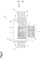
- FIG. 5 is a front view illustrating the accumulator, the rotating body, and the stopper as viewed from the supplier side.
- the stopper 6 is disposed on the side where the electrode plate 2 is pushed out with respect to the conveyor 5.
- the stopper 6 abuts against the tip of the electrode plate 2 in the push-out direction D1 and prevents the electrode plate 2 from being pushed out from the conveyor 5.
- the stopper 6 includes a back plate 7, guides 8 and 9.
- the back plate 7 has an opposing surface 7a opposing the conveyor 5.
- the opposing surface 7a has a substantially rectangular shape.
- the opposing surface 7a abuts against the electrode plate 2 and appropriately determines the position of the tip of the electrode plate 2 in the push-out direction D1.
- the guides 8 and 9 are provided on the opposing surface 7a so as to face each other in the opposing direction D3 and extend along the conveying direction D2.
- the guides 8 and 9 include guide surfaces 8a and 9a opposing each other in the opposing direction D3.
- the gap between the guide surfaces 8a and 9a narrows toward the downstream side in the conveying direction D2.
- the gap between the guide surfaces 8a and 9a at the downstream side end in the conveying direction D2 coincides with the width of the electrode plate 2.
- the guide surfaces 8a and 9a appropriately determine the position of the electrode plate 2 in the opposing direction D3.
- the accumulator 3 Disposed directly below the conveyor 5 is the accumulator 3 where a plurality of the electrode plates 2 is accumulated.
- the accumulator 3 accumulates the electrode plates 2 conveyed and dropped by the conveyor 5.
- the accumulator 3 includes ascending and descending functions.
- the accumulator 3 descends by the thickness of the electrode plate 2 each time the electrode plate 2 is conveyed. As a result, the fall distance of the electrode plate 2 is kept constant.
- the fall distance of the electrode plate 2 is set to, for example, 30 mm or less.
- the electrode plate 2 is first supplied to the conveyor 5 by the supplier 4.
- the electrode plate 2 is supplied between the rotating shafts 11 and 21 of the rotating bodies 10 and 20.
- the rotating bodies 10 and 20 are at rest at the reference rotation position.
- the rotating bodies 10 and 20 rotate once from the reference rotation position.
- the electrode plate 2 is pushed out toward the stopper 6.
- the projections 14 and 24 are provided so as to avoid the regions R3 and R4. In the regions R3 and R4, a collision is likely to occur between the projections 14 and 24 and the pair of tip side end parts 2a of the electrode plate 2 heading toward the stopper 6 from the supplier 4. Accordingly, the pair of tip side end parts 2a of the electrode plate 2 reaches the stopper 6 without colliding with the projections 14 and 24.
- the rotating bodies 10 and 20 rotate once, the rotating bodies 10 and 20 are at rest at the reference rotation position again.
- the electrode plate 2 is conveyed downward while sliding on the support surfaces 13 and 23 in a state where the electrode plate 2 abuts against the stopper 6 and enters the spiral from the inlet of the spiral.
- the rotating bodies 10 and 20 rotate once again.
- the electrode plates 2 are sequentially conveyed downward along the support surfaces 13 and 23 in a state where the electrode plates 2 abut against the stopper 6.
- the electrode plate 2 is conveyed downward in a state where the tip of the electrode plate 2 in the push-out direction D1 is positioned. Further, the electrode plate 2 is guided (regulated) by the guide surfaces 8a and 9a and positioned in the opposing direction D3.
- the end edges 12b and 22b are disposed outside the rotating shafts 11 and 21 at the reference rotation position. Accordingly, the electrode plates 2 are accumulated at the accumulator 3 by reaching the end edges 12b and 22b and simultaneously falling downward without being caught by the end edges 12b and 22b. As a result, the electrode plates 2 are conveyed to the accumulator 3 and an assembly of the electrode plates 2 is obtained with the position of the tip in the push-out direction D1 and the position in the opposing direction D3 aligned.
- the conveyor 5 includes the rotating bodies 10 and 20 including the rotating shafts 11 and 21 and the spiral parts 12 and 22.
- the spiral parts 12 and 22 are wound in directions reverse to each other and support the electrode plate 2 in the support regions R1 and R2. Accordingly, once the rotating bodies 10 and 20 rotate in directions reverse to each other, the electrode plate 2 is pushed out in a state where the electrode plate 2 is supported by the support regions R1 and R2.
- the stopper 6 is disposed on the side where the electrode plate 2 is pushed out. Accordingly, the electrode plate 2 is conveyed downward along the opposing surface 7a while abutting against the opposing surface 7a of the stopper 6 in a state where the electrode plate 2 is supported by the support regions R1 and R2. As a result, damage to the electrode plate 2 can be suppressed as compared with a case where the electrode plate 2 is dropped without support after abutting against a backing plate.
- the conveyance device 1 is provided with the supplier 4.
- the supplier 4 supplies the electrode plate 2 to the conveyor 5 from the side opposite to the stopper 6 with respect to the conveyor 5. Accordingly, the electrode plate 2 can be easily supplied to the conveyor 5.
- the rotating bodies 10 and 20 rotate once from the reference rotation position each time the supplier 4 supplies the electrode plate 2 to the conveyor 5. As a result, interference between the electrode plates 2 can be avoided. As a result, damage to the electrode plate 2 can be further suppressed.
- the end edges 12b and 22b are disposed outside the support regions R1 and R2. Accordingly, the electrode plate 2 can be sent out from the pair of spiral parts 12 and 22 without being caught by the end edges 12b and 22b.
- the spiral parts 12 and 22 include the projections 14 and 24 provided on the support surfaces 13 and 23. Accordingly, the projections 14 and 24 abut against the electrode plate 2 and support the electrode plate 2. Accordingly, damage to the electrode plate 2 can be further suppressed by, for example, the projections 14 and 24 being disposed such that the projections 14 and 24 abut the electrode plate 2 while avoiding the damage-prone part of the electrode plate 2.
- a step is formed at the upper and lower end parts of the electrode plate 2 as described above. At this step part, peeling and tearing of the paper covering the electrode material are likely to occur due to friction with the support surfaces 13 and 23.
- the projections 14 and 24 may be disposed such that the projections 14 and 24 abut against the electrode plate 2 while avoiding the place.
- the projections 14 and 24 are provided so as to avoid the regions R3 and R4. In the regions R3 and R4, a collision is likely to occur between the projections 14 and 24 and the pair of tip side end parts 2a of the electrode plate 2 heading toward the stopper 6 from the supplier 4. Accordingly, it is possible to suppress damage to the pair of tip side end parts 2a of the electrode plate 2 attributable to a collision with the projections 14 and 24.
- the projections 14 and 24 are provided from positions upstream of the regions R5 and R6 in the conveying direction D2 and downstream of the regions R3 and R4 in the conveying direction D2. Accordingly, it is possible to support the electrode plate 2 by means of the projections 14 and 24 when the electrode plate 2 supplied to the conveyor 5 has reached the stopper 6. Accordingly, it is possible to convey the electrode plate 2 while suppressing the friction between the electrode plate 2 and the support surface 13 that is attributable to the rotation of the rotating bodies 10 and 20. As a result, it is possible to further suppress the peeling and tearing of the paper covering the electrode material of the electrode plate 2.
- the projections 14 and 24 are provided up to the end edges 12b and 22b.
- the electrode plate 2 remains supported by the projections 14 and 24 from a time when the electrode plate 2 is supplied to the conveyor 5 and reaches the stopper 6 until the conveyor 5 finishes conveying the electrode plate 2. Accordingly, it is possible to convey the electrode plate 2 while further suppressing the friction, which is attributable to the rotation of the rotating bodies 10 and 20, between the electrode plate 2 and the support surface 13. As a result, it is possible to even further suppress the peeling and tearing of the paper covering the electrode material of the electrode plate 2.
- the spiral parts 12 and 22 are wound at an equal pitch and the pitch is widened at the end edges 12a and 22a. Accordingly, the electrode plate 2 is capable of entering the spiral from the inlet of the spiral even when the electrode plate 2 supplied to the spiral parts 12 and 22 abuts against the stopper 6 and jumps up due to the resultant reaction.
- the radii of the spiral parts 12 and 22 are equal to each other. Accordingly, rotation control with respect to the spiral parts 12 and 22 can be performed with ease.
- the rotating bodies 10 and 20 rotate such that the linear velocities of the peripheral edge parts 13a and 23a become equal to each other. Accordingly, the spiral parts 12 and 22 are capable of pushing out the electrode plate 2 straight toward the stopper 6.
- the stopper 6 includes the guides 8 and 9. Accordingly, the electrode plate 2 can be guided by the guides 8 and 9.
- the guides 8 and 9 include the guide surfaces 8a and 9a.
- the gap between the guide surfaces 8a and 9a narrows toward the downstream side in the conveying direction D2. Accordingly, the electrode plate 2 can be positioned in the opposing direction of the guide surfaces 8a and 9a while being conveyed.
- the present invention is not limited to the embodiment described above.
- FIG. 6 is a top view for describing the radius of the spiral according to the embodiment.
- FIG. 7 is a top view for describing the radius of the spiral according to a first modification example.
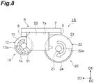
- FIG. 8 is a top view for describing the radius of the spiral according to a second modification example.
- the supplier 4 (see FIG. 1 ) is not illustrated in FIGS. 6 to 8 .
- the radii of the spiral parts 12 and 22 are equal to each other.
- the radii of the spiral parts 12 and 22 are different from each other in a conveyance device 1A according to the first modification example illustrated in FIG. 7 .
- the radius of the spiral 12 is shorter than the radius of the spiral 22.
- the shape of an electrode plate 2A conveyed in the conveyance device 1A is different from the shape of the electrode plate 2 in that the electrode plate 2A has a shape in which the lower end part of the electrode plate 2A is notched.
- the guide 8 disposed on the lower end part side of the electrode plate 2A is formed to be thicker than the guide 9 so as to be capable of abutting against the unnotched part of the lower end part of the electrode plate 2A.
- the radius of the spiral 12 is shorter than the radius of the spiral 22.
- the radii of the spiral parts 12 and 22 are different from each other. Specifically, in the conveyance device 1B, the radius of the spiral 12 is shorter than the radius of the spiral 22. The radius of the spiral 12 in the conveyance device 1B is shorter than the radius of the spiral 12 in the conveyance device 1A.
- the shape of an electrode plate 2B conveyed in the conveyance device 1B is different from the shape of the electrode plate 2 in that the electrode plate 2B has a shape such that the lower end part of the electrode plate 2B is notched, as with the shape of the electrode plate 2A.
- the guide 8 disposed on the lower end part side of the electrode plate 2B is formed to be thicker than the guide 9 so as to be capable of abutting against the unnotched part of the lower end part of the electrode plate 2B as in the conveyance device 1A.
- the radius of the spiral 12 is shorter than the radius of the spiral 22.
- the shape of the electrode plate 2B is different from the shape of the electrode plate 2 also in that the length of the electrode plate 2B in the push-out direction D1 is short.
- the rotating shaft 11 disposed on the lower end part side of the electrode plate 2B is disposed on the stopper 6 side as compared with the rotating shaft 21 so as to be capable of guiding the unnotched part of the lower end part of the electrode plate 2B.
- the radius of the spiral 12 is further shorter than the radius of the spiral 22.
- the radii of the spiral parts 12 and 22 are different from each other in the conveyance device 1A and the conveyance device 1B. Accordingly, the distances between the spiral parts 12 and 22 and the stopper 6 (guides 8 and 9 to be specific) can be different from each other in accordance with the shapes of the electrode plate 2A and the electrode plate 2B.
- the linear velocities of the peripheral edge parts 13a and 23a are equal to each other by the rotation speeds (angular velocities) of the rotating bodies 10 and 20 being different from each other.
- the conveyance device 1 may supply the electrode plate 2 by means of an external device without being provided with the supplier 4.
- the spiral parts 12 and 22 may not include the projections 14 and 24.
- the spiral parts 12 and 22 may be wound at an equal pitch as a whole. In these cases, manufacturing of the spiral parts 12 and 22 is facilitated.
- the rotating bodies 10 and 20 rotate once from the reference rotation position each time the supplier 4 supplies the electrode plate 2 to the conveyor 5.
- the present invention is not limited thereto and the rotation may be performed once or more.
- the rotation of the rotating bodies 10 and 20 may be continuous instead of being intermittent.
- the linear velocities of the peripheral edge parts 13a and 23a may be different from each other.
- the stopper 6 may not include the guides 8 and 9.
Landscapes
- Engineering & Computer Science (AREA)
- Manufacturing & Machinery (AREA)
- Chemical & Material Sciences (AREA)
- Chemical Kinetics & Catalysis (AREA)
- Electrochemistry (AREA)
- General Chemical & Material Sciences (AREA)
- Mechanical Engineering (AREA)
- Screw Conveyors (AREA)
- Stacking Of Articles And Auxiliary Devices (AREA)
- Secondary Cells (AREA)
- Battery Electrode And Active Subsutance (AREA)
- Feeding Of Articles To Conveyors (AREA)
Abstract
Description
- An aspect of the present invention relates to a conveyance device.
-
Patent Literature 1 discloses a conveyance device conveying an electrode plate for a lead storage battery. This conveyance device is provided with a pinch roller sending the electrode plate while pinching the electrode plate from above and below between front- and rear-stage unit conveyance devices. The rotation speed of the pinch roller is set so as to exceed the feed speed of the front-stage unit conveyance device. Accordingly, it is possible to quickly pass the electrode plate from the front-stage unit conveyance device to the rear-stage unit conveyance device. - Patent Literature 1: Japanese Unexamined Patent Publication No.
2005-276555 - The electrode plate may be conveyed to an accumulator where a plurality of the electrode plates is accumulated by the conveyance device provided with the pinch roller described above. In this case, the electrode plate sent out by the pinch roller is dropped and accumulated at the accumulator after abutting against a backing plate. A fragile and shape change-prone object to be conveyed such as the electrode plate may be damaged by the impact during the drop or the abutment against the backing plate.
- An aspect of the present invention provides a conveyance device capable of suppressing damage to an object to be conveyed.
- A conveyance device according to an aspect of the present invention includes a conveyor and a stopper. The conveyor conveys an object to be conveyed along a direction crossing a push-out direction of the object while pushing out the object. The stopper is disposed on a side where the object is pushed out with respect to the conveyor. The stopper abuts against the object, and prevents the object from being pushed out. The conveyor includes a pair of rotating bodies. The pair of rotating bodies includes a pair of rotating shafts and a pair of spiral parts. The pair of rotating bodies extends in a conveying direction of the object. The pair of spiral parts is spirally wound around the pair of rotating shafts. The pair of spiral parts is wound in directions reverse to each other. The pair of spiral parts supports the object in a pair of support regions between the pair of rotating shafts.
- In the conveyance device according to an aspect of the present invention, the conveyor includes the pair of rotating bodies. The pair of rotating bodies includes the pair of spiral parts spirally wound around the pair of rotating shafts. The pair of spiral parts is wound in directions reverse to each other. The pair of spiral parts supports the object in the pair of support regions between the pair of rotating shafts. Accordingly, once the pair of rotating bodies rotates, the object is pushed out in a state where the object is supported by the pair of spiral parts. The stopper is disposed on the side where the object is pushed out. Accordingly, the object is conveyed along the stopper while abutting against the stopper in a state where the object is supported by the pair of spiral parts. As a result, damage to the object can be suppressed as compared with a case where the object is dropped without support after abutting against a backing plate.
- The conveyance device according to an aspect of the present invention may further include a supplier. The supplier may supply the object to the conveyor from a side opposite to the stopper with respect to the conveyor. In this case, the object can be easily supplied to the conveyor.
- In the conveyance device according to an aspect of the present invention, the pair of rotating bodies may rotate once from a reference rotation position each time the supplier supplies the object to the conveyor. In this case, interference between the objects can be avoided. As a result, damage to the object can be further suppressed.
- In the conveyance device according to an aspect of the present invention, a pair of end edges on a downstream side in the conveying direction of the pair of spiral parts may be disposed outside the pair of support regions at the reference rotation position. In this case, the object can be sent out from the pair of spiral parts without being caught by the end edges of the pair of spiral parts on the downstream side in the conveying direction.
- In the conveyance device according to an aspect of the present invention, the pair of spiral parts may include a pair of support surfaces supporting the object and a pair of projections provided at peripheral edge parts of the pair of support surfaces. In this case, the projection abuts against the object and supports the object. Accordingly, it is possible to convey the object while suppressing the friction between the object and the support surface that is attributable to the rotation of the rotating body.
- In the conveyance device according to an aspect of the present invention, the pair of spiral parts may include a pair of support surfaces supporting the object and a pair of projections provided at peripheral edge parts of the pair of support surfaces. The pair of projections may be provided so as to avoid a stopper side crossing region at a pair of upstream side blades of the pair of spiral parts at a first pitch from an upstream side in the conveying direction at the reference rotation position, the stopper side crossing region being a region on the stopper side and one of regions where peripheral edge parts of the pair of support surfaces cross a trajectory for a tip side end part of the object to reach the stopper from the supplier when viewed from the conveying direction. In this case, the projection abuts against the object and supports the object. Accordingly, damage to the object can be further suppressed by, for example, the projections being disposed such that the projections abut against the object while avoiding the damage-prone part of the object. In addition, the projections are provided so as to avoid a region in which it is easy to collide with the tip side end part of the object heading toward the stopper from the supplier. Accordingly, it is possible to suppress damage to the tip side end part of the object attributable to a collision with the projections.
- In the conveyance device according to an aspect of the present invention, the pair of projections may be provided from positions that are downstream of the stopper side crossing region in the conveying direction and upstream of a rare end crossing region in the conveying direction at the pair of upstream side blades at the reference rotation position, the rare end crossing region being a region where a rear end of the object at the stopper and peripheral edge parts of the pair of support surfaces crossing each other when viewed from the conveying direction. In this case, it is possible to support the object by means of the projections when the object supplied to the conveyor has reached the stopper. Accordingly, it is possible to convey the object while suppressing the friction between the object and the support surface that is attributable to the rotation of the rotating bodies.
- In the conveyance device according to an aspect of the present invention, the pair of projections may be provided up to a pair of end edges on the downstream side in the conveying direction of the pair of spiral parts. In this case, it is possible to convey the object while further suppressing the friction between the object and the support surface that is attributable to the rotation of the rotating bodies.
- In the conveyance device according to an aspect of the present invention, the pair of spiral parts may be wound at an equal pitch with a pitch widened at an end edge on an upstream side in the conveying direction. In this case, the object is capable of entering the spiral from the inlet of the spiral even when the object supplied to the pair of spiral parts abuts against the stopper and jumps up due to the resultant reaction.
- In the conveyance device according to an aspect of the present invention, radii of the pair of spiral parts may be equal to each other. In this case, rotation control with respect to the pair of spiral parts can be performed with ease.
- In the conveyance device according to an aspect of the present invention, radii of the pair of spiral parts may be different from each other. In this case, the distances between the pair of rotating shafts and the stopper can be different from each other in accordance with the shape of the object.
- In the conveyance device according to an aspect of the present invention, the stopper may have an opposing surface opposing the conveyor and a pair of guides provided on the opposing surface and extending along the conveying direction. In this case, the object can be guided by the pair of guides.
- In the conveyance device according to an aspect of the present invention, the pair of guides may have a gap narrowing toward a downstream side in the conveying direction. In this case, the object can be positioned in the opposing direction of the pair of guides while being conveyed.
- In the conveyance device according to an aspect of the present invention, the pair of rotating bodies may rotate such that linear velocities of peripheral edge parts of the pair of spiral parts become equal to each other. In this case, the pair of spiral parts is capable of pushing out the object straight toward the stopper.
- In the conveyance device according to an aspect of the present invention, the object may be an electrode plate. In this case, damage to the electrode plate can be suppressed.
- According to an aspect of the present invention, it is possible to provide a conveyance device capable of suppressing damage to an object to be conveyed.
-
-
FIG. 1 is a top view illustrating a conveyance device according to an embodiment. -
FIG. 2 is a side view illustrating the conveyance device according to the embodiment. -
FIG. 3 is a cross-sectional view illustrating a pair of rotating bodies. -
FIG. 4 is a top view for describing a region where a projection is provided. -
FIG. 5 is a front view illustrating an accumulator, the rotating body, and a stopper as viewed from a supplier side. -
FIG. 6 is a top view for describing the radius of a spiral according to the embodiment. -
FIG. 7 is a top view for describing the radius of a spiral according to a first modification example. -
FIG. 8 is a top view for describing the radius of a spiral according to a second modification example. - Hereinafter, an embodiment will be described in detail with reference to accompanying drawings. In the description of the drawings, the same reference numerals are used for the same or equivalent elements and redundant description will be omitted.
-
FIG. 1 is a top view illustrating a conveyance device according to the embodiment.FIG. 2 is a side view illustrating the conveyance device according to the embodiment. Aconveyance device 1 according to the embodiment illustrated inFIGS. 1 and2 conveys anelectrode plate 2 for a lead storage battery as an object to be conveyed, which is a conveyance object. The object by theconveyance device 1 is not limited to theelectrode plate 2. For example, theconveyance device 1 is applied to a process for accumulating theelectrode plate 2 in a battery production line and sequentially conveys theelectrode plate 2. The conveyed electrode plate is accumulated at anaccumulator 3 and then sent to the next process. - The
electrode plate 2 is a thin plate-shaped member having a substantially rectangular shape. Theelectrode plate 2 has a pair of main surfaces opposing each other in a thickness direction. Theelectrode plate 2 includes a lead alloy-based support body, an electrode material held by the support body, and a current collector part (ear part) provided at the upper end part of the support body. The part between the upper and lower end parts of the support body is formed in, for example, a lattice shape by expand processing. The electrode material is formed by electrode material paste application to the lattice-shaped part of the support body. The electrode material is easily detached from the support body. Paper is attached to the surface of the electrode material so that electrode material detachment is prevented. The upper and lower end parts of the support body are exposed from a current collector. Accordingly, a step is formed at the upper and lower end parts of theelectrode plate 2. - The
conveyance device 1 is provided with asupplier 4, aconveyor 5, and astopper 6 arranged in this order. A guide 9 (described later) at thestopper 6 is not illustrated inFIG. 2 . - The
supplier 4 is disposed on the side opposite to thestopper 6 with respect to theconveyor 5. Thesupplier 4 supplies theelectrode plate 2 to theconveyor 5 from the side opposite to thestopper 6 with respect to theconveyor 5. Thesupplier 4 includes abelt conveyor 4a and arotating roller 4b. Thebelt conveyor 4a conveys theelectrode plate 2 toward theconveyor 5. Thebelt conveyor 4a is disposed such that the conveying-direction downstream side end part of thebelt conveyor 4a is higher than the conveying-direction upstream side end part of thebelt conveyor 4a and conveys theelectrode plate 2 obliquely upward. Therotating roller 4b is disposed between thebelt conveyor 4a and theconveyor 5 and adjacent to the conveying-direction downstream side end part of thebelt conveyor 4a. - The upper surface of the
rotating roller 4b is positioned on a substantially extended line of the upper surface of thebelt conveyor 4a. Accordingly, theelectrode plate 2 conveyed by thebelt conveyor 4a smoothly transfers onto therotating roller 4b. Therotating roller 4b rotates such that the upper surface side of therotating roller 4b advances toward theconveyor 5, accelerates theelectrode plate 2, and sends out theelectrode plate 2 to theconveyor 5. Theelectrode plate 2 jumps out obliquely upward from thesupplier 4. Subsequently, theelectrode plate 2 falls parabolically and transfers onto theconveyor 5. As a result, theelectrode plate 2 is supplied to theconveyor 5. - The
conveyor 5 is disposed between thesupplier 4 and thestopper 6. Theconveyor 5 conveys theelectrode plate 2 along a direction crossing a push-out direction D1 of theelectrode plate 2 while pushing out theelectrode plate 2 to thestopper 6 side. In the present embodiment, theconveyor 5 conveys theelectrode plate 2 downward (vertically downward) while pushing out theelectrode plate 2 in a substantially horizontal direction. In other words, the push-out direction D1 of theelectrode plate 2 in the present embodiment is a substantially horizontal direction and is a direction on thestopper 6 side with respect to theconveyor 5. A conveying direction D2 of theelectrode plate 2 is downward. - The
conveyor 5 includesrotating bodies rotating bodies bodies electrode plate 2 supplied from thesupplier 4 on both sides of theelectrode plate 2 in the opposing direction D3. The rotatingbodies shafts bodies rotating shafts -
FIG. 3 is a cross-sectional view illustrating the pair of rotating bodies. As illustrated inFIGS. 1 to 3 , the rotatingbodies spiral parts shafts spiral parts spiral parts spiral parts rotating shafts spiral parts - The pair of
rotating bodies peripheral edge parts bodies body 10 rotates counterclockwise and therotating body 20 rotates clockwise. The rotatingbodies supplier 4 supplies theelectrode plate 2 to theconveyor 5. Theconveyor 5 detects the supply of theelectrode plate 2 from thesupplier 4 by means of a sensor (not illustrated) or the like. - The
spiral parts electrode plate 2 between therotating shafts spiral parts electrode plate 2 in the support regions R1 and R2 between therotating shafts electrode plate 2 is guided (regulated) by the rotatingshafts rotating shaft 11 on therotating shaft 21 side. The virtual plane F2 is a virtual plane parallel to the virtual plane F1 and in contact with the tip of therotating shaft 21 on therotating shaft 11 side. Once the rotatingbodies supplier 4 toward thestopper 6. Accordingly, theelectrode plate 2 supported by the support regions R1 and R2 is pushed out toward thestopper 6. - The
spiral parts end edges edges spiral parts blades blades blades spiral parts spiral parts spiral parts blades 12c adjacent to each other in the conveying direction D2 at thespiral parts spiral parts - The
spiral parts spiral 12 is wound clockwise from theend edge 12a toward theend edge 12b. Thespiral 22 is wound counterclockwise from theend edge 22a toward theend edge 22b. In other words, the direction in which thespiral 12 is wound from theend edge 12a toward theend edge 12b is reverse to the direction of rotation of therotating body 10. The direction in which thespiral 22 is wound from theend edge 22a toward theend edge 22b is reverse to the direction of rotation of therotating body 20. Once the rotatingbodies electrode plate 2 supported by thespiral parts spiral parts - The end edges 12a and 22a are disposed outside the support regions R1 and R2 at the reference rotation position. Specifically, the
end edge 12a is disposed on the side opposite to the virtual plane F2 with respect to the virtual plane F1 at the reference rotation position. Theend edge 22a is disposed on the side opposite to the virtual plane F1 with respect to the virtual plane F2 at the reference rotation position. The end edges 12a and 22a are substantially parallel to the opposing direction D3 outside the support regions R1 and R2 at the reference rotation position. - The end edges 12b and 22b are disposed outside the support regions R1 and R2 at the reference rotation position. Specifically, the
end edge 12b is disposed on the side opposite to the virtual plane F2 with respect to the virtual plane F1 at the reference rotation position. Theend edge 22b is disposed on the side opposite to the virtual plane F1 with respect to the virtual plane F2 at the reference rotation position. The end edges 12b and 22b are substantially parallel to the push-out direction D1 on thestopper 6 sides of therotating shafts - The
spiral parts projections electrode plate 2 and support theelectrode plate 2. Theprojections peripheral edge parts projections projections projections electrode plate 2 is supplied onto theblades spiral parts -
FIG. 4 is a top view for describing the region where the projection is provided. The supplier 4 (seeFIG. 1 ) is not illustrated inFIG. 4 . As illustrated inFIG. 4 , at the first-pitch blades projections stopper 6 side among the four regions where a pair of trajectories L and theperipheral edge parts side end parts 2a of theelectrode plate 2 to reach thestopper 6 from thesupplier 4 as viewed from the conveying direction D2. The tipside end parts 2a are the end parts of the side positioned at the tip of theelectrode plate 2. In the regions R3 and R4, a collision is likely to occur between theprojections side end parts 2a of theelectrode plate 2 heading toward thestopper 6 from thesupplier 4. - At the first-
pitch blades projections FIG. 1 ) from positions upstream of regions R5 and R6 in the conveying direction D2 and downstream of the regions R3 and R4 in the conveying direction D2. In the regions R5 and R6, the rear end of theelectrode plate 2 that has reached thestopper 6 and theperipheral edge parts projections projections projection 14 is ahead of the region R5 in the direction of rotation of therotating body 10 and behind the region R3 in the direction of rotation of therotating body 10. The start position of theprojection 24 is ahead of the region R6 in the direction of rotation of therotating body 20 and behind the region R4 in the direction of rotation of therotating body 20. The end positions of theprojections electrode plate 2 remains supported by theprojections electrode plate 2 is supplied to theconveyor 5 and reaches thestopper 6 until theconveyor 5 finishes conveying theelectrode plate 2. - Aluminum (A5052) and the like can be used as the material of the
spiral parts -
FIG. 5 is a front view illustrating the accumulator, the rotating body, and the stopper as viewed from the supplier side. As illustrated inFIGS. 1 ,2 , and5 , thestopper 6 is disposed on the side where theelectrode plate 2 is pushed out with respect to theconveyor 5. Thestopper 6 abuts against the tip of theelectrode plate 2 in the push-out direction D1 and prevents theelectrode plate 2 from being pushed out from theconveyor 5. Thestopper 6 includes aback plate 7, guides 8 and 9. - The
back plate 7 has an opposingsurface 7a opposing theconveyor 5. The opposingsurface 7a has a substantially rectangular shape. The opposingsurface 7a abuts against theelectrode plate 2 and appropriately determines the position of the tip of theelectrode plate 2 in the push-out direction D1. Theguides surface 7a so as to face each other in the opposing direction D3 and extend along the conveying direction D2. Theguides guide surfaces 8a and 9a opposing each other in the opposing direction D3. The gap between the guide surfaces 8a and 9a narrows toward the downstream side in the conveying direction D2. The gap between the guide surfaces 8a and 9a at the downstream side end in the conveying direction D2 coincides with the width of theelectrode plate 2. The guide surfaces 8a and 9a appropriately determine the position of theelectrode plate 2 in the opposing direction D3. - Disposed directly below the
conveyor 5 is theaccumulator 3 where a plurality of theelectrode plates 2 is accumulated. Theaccumulator 3 accumulates theelectrode plates 2 conveyed and dropped by theconveyor 5. Theaccumulator 3 includes ascending and descending functions. Theaccumulator 3 descends by the thickness of theelectrode plate 2 each time theelectrode plate 2 is conveyed. As a result, the fall distance of theelectrode plate 2 is kept constant. The fall distance of theelectrode plate 2 is set to, for example, 30 mm or less. Once a predetermined number of theelectrode plates 2 are accumulated at theaccumulator 3, the accumulatedelectrode plates 2 are sent to the next process. After theelectrode plates 2 are sent out, theaccumulator 3 ascends by the thickness of the predetermined number of theelectrode plates 2 sent out and repeats the processing for accumulating theelectrode plates 2 conveyed by theconveyor 5. - In the
conveyance device 1 configured as described above, theelectrode plate 2 is first supplied to theconveyor 5 by thesupplier 4. At theconveyor 5, theelectrode plate 2 is supplied between therotating shafts rotating bodies bodies electrode plate 2 is supplied, the rotatingbodies electrode plate 2 is pushed out toward thestopper 6. Theprojections projections side end parts 2a of theelectrode plate 2 heading toward thestopper 6 from thesupplier 4. Accordingly, the pair of tipside end parts 2a of theelectrode plate 2 reaches thestopper 6 without colliding with theprojections rotating bodies bodies - The
electrode plate 2 is conveyed downward while sliding on the support surfaces 13 and 23 in a state where theelectrode plate 2 abuts against thestopper 6 and enters the spiral from the inlet of the spiral. Once thenext electrode plate 2 is conveyed to theconveyor 5, the rotatingbodies electrode plates 2 are sequentially conveyed downward along the support surfaces 13 and 23 in a state where theelectrode plates 2 abut against thestopper 6. In other words, theelectrode plate 2 is conveyed downward in a state where the tip of theelectrode plate 2 in the push-out direction D1 is positioned. Further, theelectrode plate 2 is guided (regulated) by the guide surfaces 8a and 9a and positioned in the opposing direction D3. The end edges 12b and 22b are disposed outside the rotatingshafts electrode plates 2 are accumulated at theaccumulator 3 by reaching the end edges 12b and 22b and simultaneously falling downward without being caught by the end edges 12b and 22b. As a result, theelectrode plates 2 are conveyed to theaccumulator 3 and an assembly of theelectrode plates 2 is obtained with the position of the tip in the push-out direction D1 and the position in the opposing direction D3 aligned. - As described above, in the
conveyance device 1, theconveyor 5 includes therotating bodies rotating shafts spiral parts spiral parts electrode plate 2 in the support regions R1 and R2. Accordingly, once therotating bodies electrode plate 2 is pushed out in a state where theelectrode plate 2 is supported by the support regions R1 and R2. Thestopper 6 is disposed on the side where theelectrode plate 2 is pushed out. Accordingly, theelectrode plate 2 is conveyed downward along the opposingsurface 7a while abutting against the opposingsurface 7a of thestopper 6 in a state where theelectrode plate 2 is supported by the support regions R1 and R2. As a result, damage to theelectrode plate 2 can be suppressed as compared with a case where theelectrode plate 2 is dropped without support after abutting against a backing plate. - The
conveyance device 1 is provided with thesupplier 4. Thesupplier 4 supplies theelectrode plate 2 to theconveyor 5 from the side opposite to thestopper 6 with respect to theconveyor 5. Accordingly, theelectrode plate 2 can be easily supplied to theconveyor 5. - The rotating
bodies supplier 4 supplies theelectrode plate 2 to theconveyor 5. As a result, interference between theelectrode plates 2 can be avoided. As a result, damage to theelectrode plate 2 can be further suppressed. - At the reference rotation position, the end edges 12b and 22b are disposed outside the support regions R1 and R2. Accordingly, the
electrode plate 2 can be sent out from the pair ofspiral parts - The
spiral parts projections projections electrode plate 2 and support theelectrode plate 2. Accordingly, damage to theelectrode plate 2 can be further suppressed by, for example, theprojections projections electrode plate 2 while avoiding the damage-prone part of theelectrode plate 2. In the present embodiment, a step is formed at the upper and lower end parts of theelectrode plate 2 as described above. At this step part, peeling and tearing of the paper covering the electrode material are likely to occur due to friction with the support surfaces 13 and 23. The peeling and tearing of the paper are particularly likely to occur in the place where the support surfaces 13 and 23 rub in the direction in which the step part is climbed over. Accordingly, theprojections projections electrode plate 2 while avoiding the place. - At the first-
pitch blades projections projections side end parts 2a of theelectrode plate 2 heading toward thestopper 6 from thesupplier 4. Accordingly, it is possible to suppress damage to the pair of tipside end parts 2a of theelectrode plate 2 attributable to a collision with theprojections - At the first-
pitch blades projections electrode plate 2 by means of theprojections electrode plate 2 supplied to theconveyor 5 has reached thestopper 6. Accordingly, it is possible to convey theelectrode plate 2 while suppressing the friction between theelectrode plate 2 and thesupport surface 13 that is attributable to the rotation of therotating bodies electrode plate 2. - The
projections electrode plate 2 remains supported by theprojections electrode plate 2 is supplied to theconveyor 5 and reaches thestopper 6 until theconveyor 5 finishes conveying theelectrode plate 2. Accordingly, it is possible to convey theelectrode plate 2 while further suppressing the friction, which is attributable to the rotation of therotating bodies electrode plate 2 and thesupport surface 13. As a result, it is possible to even further suppress the peeling and tearing of the paper covering the electrode material of theelectrode plate 2. - The
spiral parts electrode plate 2 is capable of entering the spiral from the inlet of the spiral even when theelectrode plate 2 supplied to thespiral parts stopper 6 and jumps up due to the resultant reaction. - The radii of the
spiral parts spiral parts bodies peripheral edge parts spiral parts electrode plate 2 straight toward thestopper 6. - The
stopper 6 includes theguides electrode plate 2 can be guided by theguides guides electrode plate 2 can be positioned in the opposing direction of the guide surfaces 8a and 9a while being conveyed. - The present invention is not limited to the embodiment described above.
- For example, the radii of the
spiral parts spiral parts FIGS. 6 to 8 .FIG. 6 is a top view for describing the radius of the spiral according to the embodiment.FIG. 7 is a top view for describing the radius of the spiral according to a first modification example.FIG. 8 is a top view for describing the radius of the spiral according to a second modification example. The supplier 4 (seeFIG. 1 ) is not illustrated inFIGS. 6 to 8 . - In the
conveyance device 1 according to the embodiment illustrated inFIG. 6 , the radii of thespiral parts spiral parts conveyance device 1A according to the first modification example illustrated inFIG. 7 . Specifically, in theconveyance device 1A, the radius of the spiral 12 is shorter than the radius of thespiral 22. The shape of anelectrode plate 2A conveyed in theconveyance device 1A is different from the shape of theelectrode plate 2 in that theelectrode plate 2A has a shape in which the lower end part of theelectrode plate 2A is notched. Accordingly, in theconveyance device 1A, theguide 8 disposed on the lower end part side of theelectrode plate 2A is formed to be thicker than theguide 9 so as to be capable of abutting against the unnotched part of the lower end part of theelectrode plate 2A. As a result, the radius of the spiral 12 is shorter than the radius of thespiral 22. - Also in a conveyance device 1B according to the second modification example illustrated in
FIG. 8 , the radii of thespiral parts spiral 22. The radius of the spiral 12 in the conveyance device 1B is shorter than the radius of the spiral 12 in theconveyance device 1A. The shape of anelectrode plate 2B conveyed in the conveyance device 1B is different from the shape of theelectrode plate 2 in that theelectrode plate 2B has a shape such that the lower end part of theelectrode plate 2B is notched, as with the shape of theelectrode plate 2A. Accordingly, in the conveyance device 1B, theguide 8 disposed on the lower end part side of theelectrode plate 2B is formed to be thicker than theguide 9 so as to be capable of abutting against the unnotched part of the lower end part of theelectrode plate 2B as in theconveyance device 1A. As a result, the radius of the spiral 12 is shorter than the radius of thespiral 22. Further, the shape of theelectrode plate 2B is different from the shape of theelectrode plate 2 also in that the length of theelectrode plate 2B in the push-out direction D1 is short. Accordingly, in the conveyance device 1B, the rotatingshaft 11 disposed on the lower end part side of theelectrode plate 2B is disposed on thestopper 6 side as compared with the rotatingshaft 21 so as to be capable of guiding the unnotched part of the lower end part of theelectrode plate 2B. As a result, the radius of the spiral 12 is further shorter than the radius of thespiral 22. - As described above, the radii of the
spiral parts conveyance device 1A and the conveyance device 1B. Accordingly, the distances between thespiral parts electrode plate 2A and theelectrode plate 2B. In theconveyance device 1A and the conveyance device 1B, the linear velocities of theperipheral edge parts FIG. 3 ) are equal to each other by the rotation speeds (angular velocities) of therotating bodies - The
conveyance device 1 may supply theelectrode plate 2 by means of an external device without being provided with thesupplier 4. In this case, the configuration of theconveyance device 1 can be simplified. Thespiral parts projections spiral parts spiral parts bodies supplier 4 supplies theelectrode plate 2 to theconveyor 5. The present invention is not limited thereto and the rotation may be performed once or more. The rotation of therotating bodies peripheral edge parts FIG. 3 ) may be different from each other. Thestopper 6 may not include theguides - 1, 1A, 1B: conveyance device, 2, 2A, 2B: electrode plate (object to be conveyed), 2a: tip side end part, 3: accumulator, 4: supplier, 5: conveyor, 6: stopper, 7: back plate, 7a: opposing surface, 8, 9: guide, 8a, 9a: guide surface, 10, 20: rotating body, 11, 21: rotating shaft, 12, 22: spiral, 12a, 22a: end edge, 12b, 22b: end edge, 12c, 22c: blade, 13, 23: support surface, 13a, 23a: peripheral edge part, 14, 24: projection, D1: push-out direction, D2: conveying direction, L: trajectory, R1, R2: support region, R3, R4: region (stopper side crossing region), R5, R6: region.
Claims (15)
- A conveyance device comprising:a conveyor conveying an object to be conveyed along a direction crossing a push-out direction of the object while pushing out the object; anda stopper disposed on a side where the object is pushed out with respect to the conveyor, abutting against the object, and preventing the object from being pushed out, whereinthe conveyor includes a pair of rotating bodies including a pair of rotating shafts extending in a conveying direction of the object and a pair of spiral parts spirally wound around the pair of rotating shafts, andthe pair of spiral parts is wound in directions reverse to each other and supports the object in a pair of support regions between the pair of rotating shafts.
- The conveyance device according to claim 1, further comprising a supplier supplying the object to the conveyor from a side opposite to the stopper with respect to the conveyor.
- The conveyance device according to claim 2, wherein the pair of rotating bodies rotates once from a reference rotation position each time the supplier supplies the object to the conveyor.
- The conveyance device according to claim 3, wherein a pair of end edges on a downstream side in the conveying direction of the pair of spiral parts is disposed outside the pair of support regions at the reference rotation position.
- The conveyance device according to any one of claims 1 to 4, wherein the pair of spiral parts includes a pair of support surfaces supporting the object and a pair of projections provided at peripheral edge parts of the pair of support surfaces.
- The conveyance device according to claim 3 or 4, wherein
the pair of spiral parts includes a pair of support surfaces supporting the object and a pair of projections provided at peripheral edge parts of the pair of support surfaces, and
the pair of projections is provided so as to avoid a stopper side crossing region at a pair of upstream side blades of the pair of spiral parts at a first pitch from an upstream side in the conveying direction at the reference rotation position, the stopper side crossing region being a region on the stopper side and one of regions where peripheral edge parts of the pair of support surfaces cross a trajectory for a tip side end part of the object to reach the stopper from the supplier when viewed from the conveying direction. - The conveyance device according to claim 6, wherein the pair of projections is provided from positions that are downstream of the stopper side crossing region in the conveying direction and upstream of a rare end crossing region in the conveying direction at the pair of upstream side blades at the reference rotation position, the rare end crossing region being a region where a rear end of the object at the stopper and peripheral edge parts of the pair of support surfaces crossing each other when viewed from the conveying direction.
- The conveyance device according to any one of claims 5 to 7, wherein the pair of projections is provided up to a pair of end edges on a downstream side in the conveying direction of the pair of spiral parts.
- The conveyance device according to any one of claims 1 to 8, wherein the pair of spiral parts is wound at an equal pitch with a pitch widened at a pair of end edges on an upstream side in the conveying direction of the pair of spiral parts.
- The conveyance device according to any one of claims 1 to 9, wherein radii of the pair of spiral parts are equal to each other.
- The conveyance device according to any one of claims 1 to 9, wherein radii of the pair of spiral parts are different from each other.
- The conveyance device according to any one of claims 1 to 11, wherein the stopper has an opposing surface opposing the conveyor and a pair of guides provided on the opposing surface and extending along the conveying direction.
- The conveyance device according to claim 12, wherein the pair of guides includes a gap narrowing toward a downstream side in the conveying direction.
- The conveyance device according to any one of claims 1 to 13, wherein the pair of rotating bodies rotates such that linear velocities of peripheral edge parts of the pair of spiral parts become equal to each other.
- The conveyance device according to any one of claims 1 to 14, wherein the object is an electrode plate.
Applications Claiming Priority (2)
| Application Number | Priority Date | Filing Date | Title |
|---|---|---|---|
| JP2017094162 | 2017-05-10 | ||
| PCT/JP2018/017273 WO2018207673A1 (en) | 2017-05-10 | 2018-04-27 | Conveyance device |
Publications (2)
| Publication Number | Publication Date |
|---|---|
| EP3546398A1 true EP3546398A1 (en) | 2019-10-02 |
| EP3546398A4 EP3546398A4 (en) | 2020-04-08 |
Family
ID=64104637
Family Applications (1)
| Application Number | Title | Priority Date | Filing Date |
|---|---|---|---|
| EP18797721.0A Withdrawn EP3546398A4 (en) | 2017-05-10 | 2018-04-27 | Conveyance device |
Country Status (4)
| Country | Link |
|---|---|
| EP (1) | EP3546398A4 (en) |
| JP (1) | JP7085787B2 (en) |
| CN (1) | CN110603211B (en) |
| WO (1) | WO2018207673A1 (en) |
Families Citing this family (4)
| Publication number | Priority date | Publication date | Assignee | Title |
|---|---|---|---|---|
| AT522645A1 (en) * | 2019-06-13 | 2020-12-15 | Rosendahl Nextrom Gmbh | Method and device for stacking plate-shaped objects |
| CN111361812B (en) * | 2020-03-19 | 2021-06-22 | 厦门安耐捷机电设备科技有限公司 | Up-down paper feeding device for universal plate wrapping machine |
| CN113148587A (en) * | 2021-05-22 | 2021-07-23 | 沈阳天通电气有限公司 | Automatic lamination device and process method for finned radiator |
| CN117125492B (en) * | 2023-10-27 | 2024-01-02 | 山西雅美德印刷科技有限公司 | Finished product conveying device for plane printing |
Family Cites Families (10)
| Publication number | Priority date | Publication date | Assignee | Title |
|---|---|---|---|---|
| FR704938A (en) * | 1930-01-22 | 1931-05-28 | Maison Breguet | Freight lifts with adjustable flow |
| GB522157A (en) * | 1938-12-02 | 1940-06-11 | Barry Henry & Cook Ltd | Improvements relating to screw conveyors |
| GB1307759A (en) * | 1970-09-04 | 1973-02-21 | Electric Power Storage Ltd | Handling rectangular plates |
| JP3024894B2 (en) * | 1993-12-02 | 2000-03-27 | ポーラ化成工業株式会社 | Transfer device |
| JP3009550U (en) * | 1994-09-28 | 1995-04-04 | 知通 臼杵 | Shredder feeding device |
| IT1285963B1 (en) * | 1996-06-21 | 1998-06-26 | Gd Spa | METHOD AND DEVICE FOR THE CONVEYANCE WITH OVERTURNING OF CIGARETTE PACKAGES |
| JP3233085B2 (en) * | 1997-11-14 | 2001-11-26 | 株式会社新潟鉄工所 | Transfer device |
| JP2005276555A (en) | 2004-03-24 | 2005-10-06 | Shin Kobe Electric Mach Co Ltd | Lead plate battery transport device |
| CN200949930Y (en) * | 2006-08-29 | 2007-09-19 | 万向钱潮股份有限公司 | Solar energy assembly glass frame installing machine |
| JP5547320B1 (en) * | 2013-03-19 | 2014-07-09 | 第一施設工業株式会社 | Transport device |
-
2018
- 2018-04-27 WO PCT/JP2018/017273 patent/WO2018207673A1/en not_active Ceased
- 2018-04-27 CN CN201880030397.5A patent/CN110603211B/en active Active
- 2018-04-27 EP EP18797721.0A patent/EP3546398A4/en not_active Withdrawn
- 2018-04-27 JP JP2019517576A patent/JP7085787B2/en active Active
Also Published As
| Publication number | Publication date |
|---|---|
| EP3546398A4 (en) | 2020-04-08 |
| CN110603211A (en) | 2019-12-20 |
| JPWO2018207673A1 (en) | 2020-03-12 |
| WO2018207673A1 (en) | 2018-11-15 |
| JP7085787B2 (en) | 2022-06-17 |
| CN110603211B (en) | 2021-10-01 |
Similar Documents
| Publication | Publication Date | Title |
|---|---|---|
| CN110603211B (en) | transport device | |
| KR102539551B1 (en) | Glass interleaf paper, glass plate packing body, method for stacking glass interleaf paper, and device for stacking glass interleaf paper | |
| CN102803102A (en) | Device for transporting containers | |
| CN102380707A (en) | Conveyor system | |
| EP3138793B1 (en) | Conveyor device | |
| CN216585220U (en) | Double-sided etching device for lead frame | |
| WO2014057736A1 (en) | Glass plate conveyance device and glass plate conveyance method | |
| CN210682294U (en) | Conveying device with automatic correction function | |
| JP2008120468A (en) | Automatic transfer device | |
| CN115676331B (en) | Conveyors and conveying systems | |
| CN204280590U (en) | Gapless transition carrier roller group | |
| JP5713802B2 (en) | Container assembly device | |
| CN101835698B (en) | Methods and apparatus for transporting substrate carriers | |
| CN102815499A (en) | Conveyer belt device | |
| CN112058921A (en) | Guiding device | |
| CN102826356B (en) | Straightening unit of conveying belt | |
| CN223983132U (en) | Bearing ball feeding and conveying device | |
| CN215923457U (en) | Transmission device | |
| CN220115424U (en) | Improved structure of proportioning bin conveyor belt | |
| CN102976044B (en) | Height adjusting assembly of transmission belt system | |
| JP2016037380A (en) | Component attitude control device | |
| KR20210111161A (en) | Aligning and feeding apparatus | |
| CN216189249U (en) | Conveying steering device | |
| JP2022034668A (en) | Container transport device | |
| CN222970395U (en) | Conveying device for electronic product detection |
Legal Events
| Date | Code | Title | Description |
|---|---|---|---|
| PUAI | Public reference made under article 153(3) epc to a published international application that has entered the european phase |
Free format text: ORIGINAL CODE: 0009012 |
|
| STAA | Information on the status of an ep patent application or granted ep patent |
Free format text: STATUS: REQUEST FOR EXAMINATION WAS MADE |
|
| 17P | Request for examination filed |
Effective date: 20190626 |
|
| AK | Designated contracting states |
Kind code of ref document: A1 Designated state(s): AL AT BE BG CH CY CZ DE DK EE ES FI FR GB GR HR HU IE IS IT LI LT LU LV MC MK MT NL NO PL PT RO RS SE SI SK SM TR |
|
| AX | Request for extension of the european patent |
Extension state: BA ME |
|
| A4 | Supplementary search report drawn up and despatched |
Effective date: 20200310 |
|
| RIC1 | Information provided on ipc code assigned before grant |
Ipc: H01M 4/04 20060101ALI20200304BHEP Ipc: B65G 57/03 20060101ALI20200304BHEP Ipc: B65G 33/06 20060101AFI20200304BHEP Ipc: H01M 10/04 20060101ALI20200304BHEP Ipc: B65G 47/74 20060101ALI20200304BHEP |
|
| DAV | Request for validation of the european patent (deleted) | ||
| DAX | Request for extension of the european patent (deleted) | ||
| 18D | Application deemed to be withdrawn |
Effective date: 20201007 |