EP3546261A1 - Deflector structure for sunroof device - Google Patents
Deflector structure for sunroof device Download PDFInfo
- Publication number
- EP3546261A1 EP3546261A1 EP17874685.5A EP17874685A EP3546261A1 EP 3546261 A1 EP3546261 A1 EP 3546261A1 EP 17874685 A EP17874685 A EP 17874685A EP 3546261 A1 EP3546261 A1 EP 3546261A1
- Authority
- EP
- European Patent Office
- Prior art keywords
- arm portion
- pivoted
- fixed part
- lock member
- lock
- Prior art date
- Legal status (The legal status is an assumption and is not a legal conclusion. Google has not performed a legal analysis and makes no representation as to the accuracy of the status listed.)
- Granted
Links
Images



Classifications
-
- B—PERFORMING OPERATIONS; TRANSPORTING
- B60—VEHICLES IN GENERAL
- B60J—WINDOWS, WINDSCREENS, NON-FIXED ROOFS, DOORS, OR SIMILAR DEVICES FOR VEHICLES; REMOVABLE EXTERNAL PROTECTIVE COVERINGS SPECIALLY ADAPTED FOR VEHICLES
- B60J7/00—Non-fixed roofs; Roofs with movable panels, e.g. rotary sunroofs
- B60J7/22—Wind deflectors for open roofs
Definitions
- the present invention relates to a deflector structure for a sunroof device.
- a deflector structure for a sunroof device is widely known to include a net deflector (hereinafter referred to as an "affected part") that is stretched out when in use to receive onrushing air, and is folded back and stored under the roof when not in use.
- Patent Document 1 discloses a deflector structure including an arm portion that holds an upper end portion of an affected part and is vertically pivoted, and a spring that biases the arm portion upward, wherein the arm portion is biased upward by the spring when in use to stretch out the affected part.
- Patent Document 1 The deflector structure of Patent Document 1 is therefore provided with a locking lever for locking deformation of the spring when the affected part is stretched out, to inhibit the arm portion from being pivoted.
- Patent Document 1 Japanese Patent Application Publication No. 2016-60480
- the related art described above has a structure to lock the spring by the locking lever for indirectly locking the arm portion being pivoted via the spring, to have problems of making the structure complicated and decreasing assembly productivity.
- the present invention has been made in view of such problems, and is intended to provide a deflector structure for a sunroof device that inhibits an arm portion from being pivoted, when the vehicle traveling, with a simple structure.
- the present invention provides a deflector structure for a sunroof device, including: a fixed part that is fixed to a vehicle body; an affected part that is arranged anterior to the fixed part and is affected by onrushing air; an arm portion that has one end pivotally connected to the fixed part and the other end holding the affected part, and is vertically pivoted about the fixed part; and a lock member that has one end pivotally connected to the arm portion and the other end pivoted in conjunction with the arm portion being pivoted, wherein the other end of the lock member is in contact with the fixed part and raised, at a predetermined pivot position, to lock the arm portion being pivoted toward a direction to approach the fixed part.
- the lock member directly locks the arm portion being pivoted, to allow for inhibiting the arm portion from being pivoted, when the vehicle traveling, with a simple structure.
- the lock member preferably has an unlocking portion that, when a pressing load is applied thereto in a locking state, unlocks the locking state.
- the deflector structure preferably further includes a guide member that has one end connected to the arm portion and the other end connected to the lock member, and guides the lock member so as to be pivoted to a position where the lock member is in contact with the fixed part and raised.
- the lock member has a curved surface on the other end to have a convex downward shape in a raised state, while the fixed part is formed to include a contact surface having a curved surface in a concave downward shape.
- the deflector structure for the sunroof device inhibits the arm portion from being pivoted, when the vehicle traveling, with a simple structure.
- a sunroof device R includes a roof panel 2 for covering and uncovering an opening 3a in a substantially rectangular shape formed in a fixed roof 3 of a vehicle body, and a deflector 1 projecting upward from the fixed roof 3 along a front edge of the opening 3a when the roof panel 2 slides rearward to uncover the opening 3a.
- a pressing shoe 2a that pushes down the deflector 1 when the roof panel 2 slides forward.
- side frames Arranged under both side edges of the opening 3a are side frames (not shown), each having a function of guiding the roof panel 2 to slide and a function of supporting the deflector 1.
- a front frame Arranged under the front edge of the opening 3a is a front frame (not shown) connecting the front ends of both of the side frames therewith.
- the deflector 1 includes: a fixed part 10 that is fixed to a side frame of a vehicle body; an affected part 20 that is arranged anterior to the fixed part 10 and affected by onrushing air; a lower holder 30 that holds a lower end of the affected part 20, and an upper holder 40 that holds the upper end of the affected part 20 and is vertically pivotable.
- the deflector 1 includes: a biasing member 50 for biasing the upper holder 40 upward; a lock member 60 for locking at a predetermined pivot position the upper holder 40 being pivoted downward; and a guide member 70 for guiding the lock member 60 to the predetermined pivot position.
- the fixed part 10 extends in the front-rear direction along the side edge of the opening 3a.
- the fixed part 10 includes a base part 11 and a support part 12.
- the base part 11 is provided with a pivot support pin 13 along the vehicle width direction for supporting the upper holder 40 being pivoted.
- the base part 11 is provided with a mounting support pin 14 along the vehicle width direction and anterior to the pivot support pin 13 for mounting the biasing member 50.
- the support part 12 is formed continuously to the front end of the base part 11.
- the support part 12 is a part in a plate shape to support the lock member 60.
- a contact surface 15 is formed on an upper surface of the support portion 12 at its front end so as to be in contact with the other end 61a of the lock member 60.
- the contact surface 15 has a curved surface in a concave downward shape.
- the affected part 20 is a part that is stretched out when in use to receive onrushing air, and is folded back and stored under the roof when not in use.
- the affected part 20 extends from the front edge of the opening 3a to the front side of the side edge.
- the affected part 20 is composed of a mesh-like member made of fine cloth or resin, for example.
- the affected part 20 has its lower edge formed to have a roll shape in side cross section.
- the roll portion has a metal wire 80 inserted therein.
- the wire 80 continuously extends from the front edge of the opening 3a via the front side of the side edge to the fixed part 10.
- the wire 80 inserted into the roll portion is inserted and held in a groove portion of the lower holder 30.
- the lower holder 30 has a central fixing portion 31 extending in the vehicle width direction along the front edge of the opening 3a, and a cover portion 32 extending outward in the vehicle width direction from both ends of the central fixing portion 31 and being orthogonally bent to further extend rearward.
- the central fixing portion 31 is composed of a plate-like member made of metal or resin, for example.
- the central fixing portion 31 is fixed to the front frame by a fastening member or the like.
- the central fixing portion 31 is formed at its front edge with a groove portion 33 in a U-shape opening rearward (see FIG. 3 ).
- the cover portion 32 covers the wire 80 inserted into the roll portion.
- the cover portion 32 is formed of a flexible resin material, for example.
- the upper holder 40 has a central holder portion 41 extending in the vehicle width direction along the front edge of the opening 3a, and arm portions 42 being orthogonally bent from both ends of the central holder portion 41 and extending rearward. Both ends of the affected part 20 are mounted between the upper holder 40 and the lower holder 30 so as to come around halfway of the arm portion 42.
- the upper holder 40 is formed of a resin material, for example.
- the front end of the arm portion 42 holds the upper end of the affected part 20, as shown in FIG. 2 .
- the rear end of the arm portion 42 is vertically pivotally connected to the fixed part 10 via the pivot support pin 13.
- the arm portion 42 is formed on its rear end with a stopper portion 43.
- the stopper portion 43 is composed of a step formed by a part of the arm portion 42 being bulged outward in the vehicle width direction.
- the stopper portion 43 is a portion that is in contact with an unlocking portion 62 to be described later when the lock member 60 is pivoted, to inhibit the lock member 60 from being pivoted.
- the arm portion 42 is formed on its lower surface with an engaging portion 44 protruding downward.
- the biasing member 50 is a member for biasing the arm portion 42 upward as shown in FIG. 2 , and is composed of a torsion coil spring, for example.
- the biasing member 50 is attached to the mounting support pin 14 of the fixed portion 10 at a position anterior to the pivot support pin 13. One end of the biasing member 50 is in contact with a lower surface of the arm portion 42, while the other end is in contact with an upper surface of the support portion 12.
- the lock member 60 is a member for inhibiting the arm portion 42 at a predetermined pivot position from being pivoted downward. As shown in FIG. 2 , the lock member 60 is composed of a plate-like material made of resin, for example. The lock member 60 is arranged at a position anterior to the biasing member 50. One end of the lock member 60 is attached to a lock pivot shaft 64 formed in the arm portion 42 so as to be pivoted in the front-rear direction. The lock member 60 pivots about the lock pivot shaft 64 in conjunction with the arm portion 42 being pivoted.
- the lock member 60 mainly includes a lock main body 61, the unlocking portion 62, and a through-hole 63.
- the lock main body 61 When the roof panel 2 slides rearward to uncover the opening 3a, the lock main body 61 is in contact with the fixed part 10 and raised substantially vertically between the fixed part 10 and the arm portion 42, to lock the arm portion 42 being pivoted downward. As shown in FIG. 4 , the lock main body 61 has a curved surface on the other end 61a to have a convex downward shape in the raised state.
- the lock main body 61 is formed on its side surface in the vehicle width direction with a rib 65 for enhancing the strength, as shown in FIG. 5 .
- the rib 65 is formed on some portion thereof (at an end closer to the other end 61a, in the present embodiment) with a contact rib 66 which is more raised than other portions of the rib 65.
- the contact rib 66 is (slidably) in contact with a side frame (not shown) or is arranged to have a slight gap, to play a role of suppressing backlash in the vehicle width direction of the lock member 60.
- the lock main body 61 is formed, on its inner side in the vehicle width direction at a position closer to the other end 61a, with an engaging portion 67 to protrude from the inner side.
- the through-hole 63 is formed in the lock main body 61 at one end thereof (a portion adjacent to the unlocking portion 62), to allow the lock pivot shaft 64 to be inserted therethrough.
- the through-hole 63 works as a mounting portion attached to the arm portion 42 via the lock pivot shaft 64.
- the unlocking portion 62 is formed to continue from the lock main body 61, as shown in FIG. 2 .
- the unlocking portion 62 is a portion that extends obliquely upward from the through-hole 63 rearward, in a locking state of the lock main body 61 locking the arm portion 42 being pivoted downward.
- the unlocking portion 62 is arranged to face the stopper portion 43 in the locking state.
- the unlocking portion 62 has its front end protruding above the upper surface of the arm portion 42 in the locking state. In the locking state, when the unlocking portion 62 is pressed forward by the pressing shoe 2a, the lock main body 61 has its front end being pivoted backward about the lock pivot shaft 64 to transition from the raised state to an inclined state, to unlock the locking state of the arm portion 42.
- the guide member 70 is a member that guides the lock main body 61 so as to be pivoted forward to a position where the lock main body 61 is in contact with the fixed portion 10 and raised.
- the guide member 70 is composed of a tension spring arranged at a position anterior to the lock body 61.
- One end of the guide member 70 is engaged with the engaging portion 44 of the arm portion 42, while the other end is engaged with the engaging portion 67 (see FIG. 5 ) of the lock main body 61.
- the deflector structure for a sunroof device is basically configured as described above. Next, its function will be described with reference to FIGS. 6A to 6C and 7 . First, a description will be given of the function at a time of the roof panel 2 being opened.
- the pressing shoe 2a provided on the lower surface of the roof panel 2 presses the arm portion 42 downward against a biasing force of the biasing member 50.
- the affected portion 20 is folded and stored under the roof.
- the lock main body 61 is in a collapsed state between the fixed portion 10 and the arm portion 42.
- the lock main body 61 is in contact with the fixed portion 10 and raised substantially vertically between the fixed portion 10 and the arm portion 42. In other words, the lock main body 61 is raised so that the normal to the contact surface 15 substantially overlaps with the central axis of the lock main body 61. In this state, the lock main body 61 locks the arm portion 42 being pivoted downward. Note that the roof panel 2 is open and the pressing shoe 2a is therefore positioned posterior to the unlocking portion 62. Additionally, the amount of pivoting the arm portion 42 is configured to be determined from the length (height dimension) of the affected part 20.
- the arm portion 42 is in a collapsed state. In this state, the affected part 20 is folded and stored under the roof. In addition, the lock main body 61 is in a collapsed state between the fixed portion 10 and the arm portion 42.
- the lock member 60 directly locks the arm portion 42 being pivoted downward, to inhibit the arm portion 42 from being pivoted when the vehicle traveling.
- the lock mechanism is formed in a simple structure, to improve assembly productivity.
- the lock main body 61 is pivoted rearward , transitioning from the raised state to the inclined state, to unlock the locking state of the arm portion 42.
- the locking state is easily unlocked by the simple configuration of the lock member 60 additionally having the unlocking portion 62.
- the existing pressing shoe 2a for pushing the arm portion 42 downward is used in the present embodiment to press the unlocking portion 62, to mitigate a cost increase from having the lock member 60.
- the guide member 70 is provided for guiding the lock main body 61 so as to be pivoted forward to a position where the lock main body 61 is in contact with the fixed portion 10 and raised, to allow the guide member 70 to guide the lock member 60 accurately and quickly to the position for the locking.
- the lock main body 61 of the present embodiment has a curved surface on the other end 61a to have a convex downward shape in the raised state, while the fixed part 10 is formed to include the contact surface 15 having a curved surface in a concave downward shape, to be in contact with the other end 61a of the lock main body 61.
- the contact surface 15 can be flat, but having a curved surface allows the lock main body 61 to be smoothly pivoted. That is, the lock member 60 is capable of fulfilling the locking function even when the predetermined pivot position varies at the time of the lock member 60 being raised, due to the tolerance of the affected part 20, the arm portion 42, the lock member 60, and the like, to inhibit the arm portion 42 more reliably from being pivoted when the vehicle traveling.
- a technique of increasing the biasing force of the biasing member 50 is conceivable as another means for inhibiting the arm portion 42 from being pivoted downward when the vehicle traveling.
- the lock member 60 directly locks and unlocks the arm portion 42 being pivoted downward, to have no need of increasing the biasing force of the biasing member 50, and to inhibit the arm portion 42 from being pivoted downward when the vehicle traveling, while suitably securing the open/close performance of the roof panel 2.
- the shape of the lock member 60 may be appropriately modified, as long as the arm portion 42 being pivoted downward is locked.
- the curvature radius of the curved surface of the contact surface 15 is preferably set as appropriate to such an extent that the lock member 60 is smoothly pivoted and is raised at a predetermined position, and that the tolerance of respective members is accepted.
- the contact surface 15 may have a flat surface.
- the guide member 70 may be dispensed with, as long as the lock member 60 is suitably pivotable.
Landscapes
- Engineering & Computer Science (AREA)
- Mechanical Engineering (AREA)
- Lock And Its Accessories (AREA)
- Seal Device For Vehicle (AREA)
- Fittings On The Vehicle Exterior For Carrying Loads, And Devices For Holding Or Mounting Articles (AREA)
Abstract
Description
- The present invention relates to a deflector structure for a sunroof device.
- A deflector structure for a sunroof device is widely known to include a net deflector (hereinafter referred to as an "affected part") that is stretched out when in use to receive onrushing air, and is folded back and stored under the roof when not in use.
Patent Document 1, for example, discloses a deflector structure including an arm portion that holds an upper end portion of an affected part and is vertically pivoted, and a spring that biases the arm portion upward, wherein the arm portion is biased upward by the spring when in use to stretch out the affected part. - Incidentally, if the affected part in a stretched out state receives strong onrushing air, when the vehicle traveling at a high speed or the like, there is a risk of the affected part being pushed backward by wind force to pull down the arm portion against the biasing force of the spring. In addition, when the vehicle travels at a high speed to follow a leading vehicle, there is a risk of the onrushing air having different onrushing levels due to turbulence caused by the leading vehicle, to cause the arm portion to be flapped up and down against the biasing force of the spring.
- The deflector structure of
Patent Document 1 is therefore provided with a locking lever for locking deformation of the spring when the affected part is stretched out, to inhibit the arm portion from being pivoted. - Patent Document 1: Japanese Patent Application Publication No.
2016-60480 - However, the related art described above has a structure to lock the spring by the locking lever for indirectly locking the arm portion being pivoted via the spring, to have problems of making the structure complicated and decreasing assembly productivity.
- The present invention has been made in view of such problems, and is intended to provide a deflector structure for a sunroof device that inhibits an arm portion from being pivoted, when the vehicle traveling, with a simple structure.
- In order to solve such problems, the present invention provides a deflector structure for a sunroof device, including: a fixed part that is fixed to a vehicle body; an affected part that is arranged anterior to the fixed part and is affected by onrushing air; an arm portion that has one end pivotally connected to the fixed part and the other end holding the affected part, and is vertically pivoted about the fixed part; and a lock member that has one end pivotally connected to the arm portion and the other end pivoted in conjunction with the arm portion being pivoted, wherein the other end of the lock member is in contact with the fixed part and raised, at a predetermined pivot position, to lock the arm portion being pivoted toward a direction to approach the fixed part.
- According to the present invention, the lock member directly locks the arm portion being pivoted, to allow for inhibiting the arm portion from being pivoted, when the vehicle traveling, with a simple structure.
- In addition, the lock member preferably has an unlocking portion that, when a pressing load is applied thereto in a locking state, unlocks the locking state.
- This allows for easily unlocking the locking state with a simple configuration.
- Further, the deflector structure preferably further includes a guide member that has one end connected to the arm portion and the other end connected to the lock member, and guides the lock member so as to be pivoted to a position where the lock member is in contact with the fixed part and raised.
- This allows the guide member to guide the lock member accurately and quickly to the position for the locking.
- Furthermore, it is preferable in the present invention that the lock member has a curved surface on the other end to have a convex downward shape in a raised state, while the fixed part is formed to include a contact surface having a curved surface in a concave downward shape.
- This allows the lock member to fulfill the locking function even when the predetermined pivot position varies, at the time of the lock member being raised, due to the tolerance of the affected part, the arm portion, the lock member, and the like, to inhibit the arm portion more reliably from being pivoted when the vehicle traveling.
- The deflector structure for the sunroof device according to the present invention inhibits the arm portion from being pivoted, when the vehicle traveling, with a simple structure.
-
-
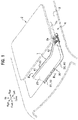
FIG. 1 is a partially broken perspective view of a deflector for a sunroof device according to the present embodiment; -
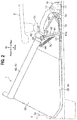
FIG. 2 is a side view of the deflector in a stretched state; -
FIG. 3 is a cross-sectional view taken along a line III-III inFIG. 1 ; -
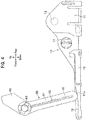
FIG. 4 is a side view of a fixed part and a lock member; -
FIG. 5 is a perspective view of the lock member; -
FIG. 6A is a side view of the deflector in a fully closed state, for demonstrating its function when a roof panel is to be opened; -
FIG. 6B is a side view of the deflector in an intermediate state, for demonstrating its function when the roof panel is being opened; -
FIG. 6C is a side view of the deflector in a stretched state, for demonstrating its function when the roof panel is opened; and -
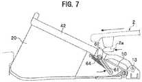
FIG. 7 is a side view of the deflector immediately after a locking state is unlocked, for demonstrating its function when the roof panel is to be closed. - Embodiments of the present invention will be described in detail with reference to drawings. In the description, the same elements will be denoted by the same reference numerals and duplicate descriptions will be omitted. Directions of up and down, right and left, and front and rear in the description are based on up and down, right and left, and front and rear as viewed from the driver's seat, and a vehicle width direction is equal to a right-left direction. In
FIG. 1 , for the purpose of illustration, adeflector 1 is shown by solid lines and broken lines, while components other than thedeflector 1 are shown by two-dot chain lines. - As shown in
FIG. 1 , a sunroof device R includes aroof panel 2 for covering and uncovering anopening 3a in a substantially rectangular shape formed in afixed roof 3 of a vehicle body, and adeflector 1 projecting upward from thefixed roof 3 along a front edge of the opening 3a when theroof panel 2 slides rearward to uncover the opening 3a. - Provided on a lower surface of the
roof panel 2 is apressing shoe 2a that pushes down thedeflector 1 when theroof panel 2 slides forward. Arranged under both side edges of theopening 3a are side frames (not shown), each having a function of guiding theroof panel 2 to slide and a function of supporting thedeflector 1. Arranged under the front edge of theopening 3a is a front frame (not shown) connecting the front ends of both of the side frames therewith. - As shown in
FIG. 2 , thedeflector 1 includes: afixed part 10 that is fixed to a side frame of a vehicle body; an affectedpart 20 that is arranged anterior to thefixed part 10 and affected by onrushing air; alower holder 30 that holds a lower end of the affectedpart 20, and anupper holder 40 that holds the upper end of the affectedpart 20 and is vertically pivotable. In addition, thedeflector 1 includes: abiasing member 50 for biasing theupper holder 40 upward; alock member 60 for locking at a predetermined pivot position theupper holder 40 being pivoted downward; and aguide member 70 for guiding thelock member 60 to the predetermined pivot position. - The
fixed part 10 extends in the front-rear direction along the side edge of the opening 3a. Thefixed part 10 includes abase part 11 and asupport part 12. Thebase part 11 is provided with apivot support pin 13 along the vehicle width direction for supporting theupper holder 40 being pivoted. Thebase part 11 is provided with amounting support pin 14 along the vehicle width direction and anterior to thepivot support pin 13 for mounting thebiasing member 50. Thesupport part 12 is formed continuously to the front end of thebase part 11. Thesupport part 12 is a part in a plate shape to support thelock member 60. Acontact surface 15 is formed on an upper surface of thesupport portion 12 at its front end so as to be in contact with theother end 61a of thelock member 60. Thecontact surface 15 has a curved surface in a concave downward shape. - The affected
part 20 is a part that is stretched out when in use to receive onrushing air, and is folded back and stored under the roof when not in use. The affectedpart 20 extends from the front edge of the opening 3a to the front side of the side edge. The affectedpart 20 is composed of a mesh-like member made of fine cloth or resin, for example. As shown inFIG. 3 , the affectedpart 20 has its lower edge formed to have a roll shape in side cross section. The roll portion has ametal wire 80 inserted therein. Thewire 80 continuously extends from the front edge of the opening 3a via the front side of the side edge to thefixed part 10. Thewire 80 inserted into the roll portion is inserted and held in a groove portion of thelower holder 30. - As shown in
FIG. 1 , thelower holder 30 has a central fixing portion 31 extending in the vehicle width direction along the front edge of the opening 3a, and a cover portion 32 extending outward in the vehicle width direction from both ends of the central fixing portion 31 and being orthogonally bent to further extend rearward. The central fixing portion 31 is composed of a plate-like member made of metal or resin, for example. The central fixing portion 31 is fixed to the front frame by a fastening member or the like. The central fixing portion 31 is formed at its front edge with agroove portion 33 in a U-shape opening rearward (seeFIG. 3 ). The cover portion 32 covers thewire 80 inserted into the roll portion. The cover portion 32 is formed of a flexible resin material, for example. - The
upper holder 40 has acentral holder portion 41 extending in the vehicle width direction along the front edge of theopening 3a, andarm portions 42 being orthogonally bent from both ends of thecentral holder portion 41 and extending rearward. Both ends of theaffected part 20 are mounted between theupper holder 40 and thelower holder 30 so as to come around halfway of thearm portion 42. Theupper holder 40 is formed of a resin material, for example. The front end of thearm portion 42 holds the upper end of theaffected part 20, as shown inFIG. 2 . The rear end of thearm portion 42 is vertically pivotally connected to the fixedpart 10 via thepivot support pin 13. Thearm portion 42 is formed on its rear end with astopper portion 43. In the present embodiment, thestopper portion 43 is composed of a step formed by a part of thearm portion 42 being bulged outward in the vehicle width direction. Thestopper portion 43 is a portion that is in contact with an unlockingportion 62 to be described later when thelock member 60 is pivoted, to inhibit thelock member 60 from being pivoted. Thearm portion 42 is formed on its lower surface with an engagingportion 44 protruding downward. - The biasing
member 50 is a member for biasing thearm portion 42 upward as shown inFIG. 2 , and is composed of a torsion coil spring, for example. The biasingmember 50 is attached to the mountingsupport pin 14 of the fixedportion 10 at a position anterior to thepivot support pin 13. One end of the biasingmember 50 is in contact with a lower surface of thearm portion 42, while the other end is in contact with an upper surface of thesupport portion 12. - The
lock member 60 is a member for inhibiting thearm portion 42 at a predetermined pivot position from being pivoted downward. As shown inFIG. 2 , thelock member 60 is composed of a plate-like material made of resin, for example. Thelock member 60 is arranged at a position anterior to the biasingmember 50. One end of thelock member 60 is attached to alock pivot shaft 64 formed in thearm portion 42 so as to be pivoted in the front-rear direction. Thelock member 60 pivots about thelock pivot shaft 64 in conjunction with thearm portion 42 being pivoted. Thelock member 60 mainly includes a lockmain body 61, the unlockingportion 62, and a through-hole 63. - When the
roof panel 2 slides rearward to uncover theopening 3a, the lockmain body 61 is in contact with the fixedpart 10 and raised substantially vertically between thefixed part 10 and thearm portion 42, to lock thearm portion 42 being pivoted downward. As shown inFIG. 4 , the lockmain body 61 has a curved surface on theother end 61a to have a convex downward shape in the raised state. - The lock
main body 61 is formed on its side surface in the vehicle width direction with arib 65 for enhancing the strength, as shown inFIG. 5 . Therib 65 is formed on some portion thereof (at an end closer to theother end 61a, in the present embodiment) with acontact rib 66 which is more raised than other portions of therib 65. Thecontact rib 66 is (slidably) in contact with a side frame (not shown) or is arranged to have a slight gap, to play a role of suppressing backlash in the vehicle width direction of thelock member 60. The lockmain body 61 is formed, on its inner side in the vehicle width direction at a position closer to theother end 61a, with an engagingportion 67 to protrude from the inner side. - The through-
hole 63 is formed in the lockmain body 61 at one end thereof (a portion adjacent to the unlocking portion 62), to allow thelock pivot shaft 64 to be inserted therethrough. The through-hole 63 works as a mounting portion attached to thearm portion 42 via thelock pivot shaft 64. - The unlocking
portion 62 is formed to continue from the lockmain body 61, as shown inFIG. 2 . The unlockingportion 62 is a portion that extends obliquely upward from the through-hole 63 rearward, in a locking state of the lockmain body 61 locking thearm portion 42 being pivoted downward. The unlockingportion 62 is arranged to face thestopper portion 43 in the locking state. The unlockingportion 62 has its front end protruding above the upper surface of thearm portion 42 in the locking state. In the locking state, when the unlockingportion 62 is pressed forward by thepressing shoe 2a, the lockmain body 61 has its front end being pivoted backward about thelock pivot shaft 64 to transition from the raised state to an inclined state, to unlock the locking state of thearm portion 42. - The
guide member 70 is a member that guides the lockmain body 61 so as to be pivoted forward to a position where the lockmain body 61 is in contact with the fixedportion 10 and raised. Theguide member 70 is composed of a tension spring arranged at a position anterior to thelock body 61. One end of theguide member 70 is engaged with the engagingportion 44 of thearm portion 42, while the other end is engaged with the engaging portion 67 (seeFIG. 5 ) of the lockmain body 61. - The deflector structure for a sunroof device according to the embodiment of the present invention is basically configured as described above. Next, its function will be described with reference to
FIGS. 6A to 6C and7 . First, a description will be given of the function at a time of theroof panel 2 being opened. - When the
roof panel 2 is closed as shown inFIG. 6A , thepressing shoe 2a provided on the lower surface of theroof panel 2 presses thearm portion 42 downward against a biasing force of the biasingmember 50. In this state, the affectedportion 20 is folded and stored under the roof. In addition, the lockmain body 61 is in a collapsed state between the fixedportion 10 and thearm portion 42. - Subsequently, when the
roof panel 2 slides rearward as shown inFIG. 6B , the pressing by thepressing shoe 2a against thearm portion 42 is gradually released, to allow thearm portion 42 to be pivoted upward about the pivotingsupport pin 13 due to the biasing force of the biasingmember 50. Theaffected part 20 is pulled upward and rearward in conjunction with thearm portion 42 being pivoted upward, and the lockmain body 61 is pivoted forward about thelock pivot shaft 64. At this time, theother end 61a of the lockmain body 61 slidably contacts thecontact surface 15 of the fixedpart 10, and the lockmain body 61 is guided to pivot forward by the biasing force of theguide member 70. - In a state of the
roof panel 2 being completely open as shown inFIG. 6C , the pressure by thepressing shoe 2a against thearm portion 42 is completely released, and theaffected part 20 is raised and stretched out in an inclined manner so that its upper end is posterior to its lower end. The lockmain body 61 is in contact with the fixedportion 10 and raised substantially vertically between the fixedportion 10 and thearm portion 42. In other words, the lockmain body 61 is raised so that the normal to thecontact surface 15 substantially overlaps with the central axis of the lockmain body 61. In this state, the lockmain body 61 locks thearm portion 42 being pivoted downward. Note that theroof panel 2 is open and thepressing shoe 2a is therefore positioned posterior to the unlockingportion 62. Additionally, the amount of pivoting thearm portion 42 is configured to be determined from the length (height dimension) of theaffected part 20. - Next, a description will be given of the function when the
roof panel 2 is closed. When theroof panel 2 slides forward from the state shown inFIG. 6C , thepressing shoe 2a first presses the unlockingportion 62 forward as shown inFIG. 7 . This causes the front end of the lockmain body 61 to be pivoted rearward (upward) about thelock pivot shaft 64, transitioning from the raised state to the inclined state, to unlock the locking state of thearm portion 42. - Subsequently, when the
roof panel 2 further slides forward to cause thepressing shoe 2a to run over the unlockingportion 62, thepressing shoe 2a pushes thearm portion 42 downward against the biasing force of the biasing member 50 (seeFIG. 6B ). At this time, the upper end of theaffected part 20 is displaced downward and forward in conjunction with thearm portion 42 being pivoted downward, and the front end of the lockmain body 61 is further pivoted rearward. - In a state of the
roof panel 2 being completely closed as shown inFIG. 6A , thearm portion 42 is in a collapsed state. In this state, theaffected part 20 is folded and stored under the roof. In addition, the lockmain body 61 is in a collapsed state between the fixedportion 10 and thearm portion 42. - According to the present embodiment described above, the
lock member 60 directly locks thearm portion 42 being pivoted downward, to inhibit thearm portion 42 from being pivoted when the vehicle traveling. Besides, according to the present embodiment, the lock mechanism is formed in a simple structure, to improve assembly productivity. - In addition, according to the present embodiment, when the unlocking
portion 62 is pressed forward by thepressing shoe 2a in a state of thearm portion 42 being locked, the lockmain body 61 is pivoted rearward , transitioning from the raised state to the inclined state, to unlock the locking state of thearm portion 42. This explains that the locking state is easily unlocked by the simple configuration of thelock member 60 additionally having the unlockingportion 62. Besides, the existingpressing shoe 2a for pushing thearm portion 42 downward is used in the present embodiment to press the unlockingportion 62, to mitigate a cost increase from having thelock member 60. - Further, according to the present embodiment, the
guide member 70 is provided for guiding the lockmain body 61 so as to be pivoted forward to a position where the lockmain body 61 is in contact with the fixedportion 10 and raised, to allow theguide member 70 to guide thelock member 60 accurately and quickly to the position for the locking. - Furthermore, the lock
main body 61 of the present embodiment has a curved surface on theother end 61a to have a convex downward shape in the raised state, while the fixedpart 10 is formed to include thecontact surface 15 having a curved surface in a concave downward shape, to be in contact with theother end 61a of the lockmain body 61. Thecontact surface 15 can be flat, but having a curved surface allows the lockmain body 61 to be smoothly pivoted. That is, thelock member 60 is capable of fulfilling the locking function even when the predetermined pivot position varies at the time of thelock member 60 being raised, due to the tolerance of theaffected part 20, thearm portion 42, thelock member 60, and the like, to inhibit thearm portion 42 more reliably from being pivoted when the vehicle traveling. - A technique of increasing the biasing force of the biasing
member 50 is conceivable as another means for inhibiting thearm portion 42 from being pivoted downward when the vehicle traveling. However, if the biasing force of the biasingmember 50 is increased, thearm portion 42 would not be easily pivoted downward, but the sliding resistance between thearm portion 42 and theroof panel 2 would be increased to degrade the open/close performance of theroof panel 2. In this respect, in the present embodiment, thelock member 60 directly locks and unlocks thearm portion 42 being pivoted downward, to have no need of increasing the biasing force of the biasingmember 50, and to inhibit thearm portion 42 from being pivoted downward when the vehicle traveling, while suitably securing the open/close performance of theroof panel 2. - Hereinabove, the embodiment of the present invention has been described, but the present invention is not limited thereto and can suitably be modified without departing from the scope of the invention. For example, the shape of the
lock member 60 may be appropriately modified, as long as thearm portion 42 being pivoted downward is locked. In addition, the curvature radius of the curved surface of thecontact surface 15 is preferably set as appropriate to such an extent that thelock member 60 is smoothly pivoted and is raised at a predetermined position, and that the tolerance of respective members is accepted. Note that thecontact surface 15 may have a flat surface. Theguide member 70 may be dispensed with, as long as thelock member 60 is suitably pivotable. -
- R
- Sunroof device
- 1
- Deflector
- 10
- Fixed part
- 15
- Contact surface
- 20
- Affected part
- 30
- Lower holder
- 40
- Upper holder
- 42
- Arm portion
- 50
- Biasing member
- 60
- Lock member
- 61
- Lock main body
- 61a
- Other end
- 62
- Unlocking portion
- 70
- Guide member
Claims (4)
- A deflector structure for a sunroof device, comprising:a fixed part that is fixed to a vehicle body;an affected part that is arranged anterior to the fixed part and is affected by onrushing air;an arm portion that has one end pivotally connected to the fixed part and the other end holding the affected part, and is vertically pivoted about the fixed part; anda lock member that has one end pivotally connected to the arm portion and the other end pivoted in conjunction with the arm portion being pivoted,wherein the other end of the lock member is in contact with the fixed part and raised, at a predetermined pivot position, to lock the arm portion being pivoted toward a direction to approach the fixed part.
- The deflector structure for a sunroof device according to claim 1, wherein the lock member has an unlocking portion that, when a pressing load is applied thereto in a locking state, unlocks the locking state.
- The deflector structure for a sunroof device according to claim 1 or 2, further comprising:
a guide member that has one end connected to the arm portion and the other end connected to the lock member,
wherein the guide member guides the lock member so as to be pivoted to a position where the lock member is in contact with the fixed part and raised. - The deflector structure for a sunroof device according to claim 1, wherein the lock member has a curved surface on the other end thereof to have a convex downward shape in a raised state, while the fixed part is formed to include a contact surface having a curved surface in a concave downward shape.
Applications Claiming Priority (2)
| Application Number | Priority Date | Filing Date | Title |
|---|---|---|---|
| JP2016228538 | 2016-11-25 | ||
| PCT/JP2017/039525 WO2018096888A1 (en) | 2016-11-25 | 2017-11-01 | Deflector structure for sunroof device |
Publications (3)
| Publication Number | Publication Date |
|---|---|
| EP3546261A1 true EP3546261A1 (en) | 2019-10-02 |
| EP3546261A4 EP3546261A4 (en) | 2020-07-08 |
| EP3546261B1 EP3546261B1 (en) | 2021-07-21 |
Family
ID=62195523
Family Applications (1)
| Application Number | Title | Priority Date | Filing Date |
|---|---|---|---|
| EP17874685.5A Active EP3546261B1 (en) | 2016-11-25 | 2017-11-01 | Deflector structure for sunroof device |
Country Status (5)
| Country | Link |
|---|---|
| US (1) | US11052738B2 (en) |
| EP (1) | EP3546261B1 (en) |
| JP (1) | JP6535423B2 (en) |
| CN (1) | CN110023121B (en) |
| WO (1) | WO2018096888A1 (en) |
Families Citing this family (3)
| Publication number | Priority date | Publication date | Assignee | Title |
|---|---|---|---|---|
| JP6535423B2 (en) | 2016-11-25 | 2019-06-26 | 八千代工業株式会社 | Deflector structure of sunroof device |
| JP7305914B2 (en) * | 2019-10-24 | 2023-07-11 | ベバスト ジャパン株式会社 | Deflector mechanism of sunroof device |
| JP7434989B2 (en) * | 2020-02-13 | 2024-02-21 | 株式会社アイシン | Vehicle sunroof unit |
Family Cites Families (17)
| Publication number | Priority date | Publication date | Assignee | Title |
|---|---|---|---|---|
| NL7510515A (en) | 1975-09-05 | 1977-03-08 | Coenen Willem Frans | Vehicle with sliding roof panel - has extending wind guard locking levers released by panel ramp faces |
| JPS5914710U (en) | 1982-07-21 | 1984-01-28 | トヨタ自動車株式会社 | Car sunroof deflector |
| DE3446916A1 (en) | 1984-12-21 | 1986-07-03 | Webasto-Werk W. Baier GmbH & Co, 8035 Gauting | VEHICLE ROOF |
| NL8500619A (en) | 1985-03-05 | 1986-10-01 | Vermeulen Hollandia Octrooien | AIR CONDUCTION MECHANISM FOR AN OPEN ROOF CONSTRUCTION AND OPEN ROOF CONSTRUCTION EQUIPPED WITH THIS AIR CONDUCTION MECHANISM. |
| JP4461876B2 (en) * | 2004-03-31 | 2010-05-12 | アイシン精機株式会社 | Deflector of vehicle sunroof device |
| DE102004043620B4 (en) | 2004-09-07 | 2008-02-14 | Webasto Ag | wind deflector |
| DE502006007162D1 (en) | 2006-04-06 | 2010-07-22 | Arvinmeritor Gmbh | Wind deflector mechanism for a vehicle sunroof system |
| JP5199933B2 (en) * | 2009-03-25 | 2013-05-15 | 八千代工業株式会社 | Sunroof device deflector |
| JP4858570B2 (en) * | 2009-04-27 | 2012-01-18 | アイシン精機株式会社 | Sunroof device for vehicle |
| DE102010044120A1 (en) * | 2010-04-14 | 2011-10-20 | Fkt Gmbh | Wind deflector for passenger motor car, has subframe elements connected with one another by knuckle, which comprises detent area for use and storage positions of deflector, and another detent area for intermediate position |
| DE102011103980A1 (en) | 2011-06-10 | 2012-12-13 | Webasto Ag | A wind deflector |
| DE102011119991B3 (en) * | 2011-12-02 | 2012-05-24 | Webasto Ag | Side panel of a vehicle roof to be opened |
| DE102013207954B4 (en) * | 2013-04-30 | 2015-12-31 | Bos Gmbh & Co. Kg | Wind deflector system for a convertible |
| EP2868504B1 (en) * | 2013-10-31 | 2019-04-24 | Inalfa Roof Systems Group B.V. | Roof closure assembly and a wind deflector arrangement |
| KR101585469B1 (en) | 2014-09-15 | 2016-01-14 | 현대자동차주식회사 | Structure for supporting sun roof deflector |
| DE202016104784U1 (en) * | 2016-08-31 | 2017-12-04 | Inalfa Roof Systems Group B.V. | Roof closure device and a wind deflector device |
| JP6535423B2 (en) | 2016-11-25 | 2019-06-26 | 八千代工業株式会社 | Deflector structure of sunroof device |
-
2017
- 2017-11-01 JP JP2018552484A patent/JP6535423B2/en active Active
- 2017-11-01 CN CN201780072659.XA patent/CN110023121B/en active Active
- 2017-11-01 US US16/464,611 patent/US11052738B2/en active Active
- 2017-11-01 WO PCT/JP2017/039525 patent/WO2018096888A1/en not_active Ceased
- 2017-11-01 EP EP17874685.5A patent/EP3546261B1/en active Active
Also Published As
| Publication number | Publication date |
|---|---|
| CN110023121B (en) | 2022-05-13 |
| JPWO2018096888A1 (en) | 2019-07-04 |
| JP6535423B2 (en) | 2019-06-26 |
| EP3546261B1 (en) | 2021-07-21 |
| CN110023121A (en) | 2019-07-16 |
| WO2018096888A1 (en) | 2018-05-31 |
| US11052738B2 (en) | 2021-07-06 |
| EP3546261A4 (en) | 2020-07-08 |
| US20200376945A1 (en) | 2020-12-03 |
Similar Documents
| Publication | Publication Date | Title |
|---|---|---|
| JP5790221B2 (en) | Vehicle roof device | |
| EP3546261B1 (en) | Deflector structure for sunroof device | |
| JP4589991B2 (en) | Sunroof device deflector | |
| US20090179462A1 (en) | Open roof construction for a vehicle | |
| US20070228779A1 (en) | Sliding roof system | |
| US20110042994A1 (en) | Vehicle seat reclining apparatus | |
| JP2011513124A (en) | Open roof structure for vehicles | |
| US20130047374A1 (en) | Vehicle door fixing apparatus and fixed wedge of same | |
| US10471854B2 (en) | Vehicular seat | |
| EP2415624A2 (en) | Deflector apparatus for vehicle | |
| US6877800B2 (en) | Sunroof device | |
| EP3162604A1 (en) | Deflector device for vehicle | |
| EP3124300B1 (en) | Sunroof device | |
| US20220018173A1 (en) | Window regulator | |
| JP2010174925A (en) | Clip | |
| US20150159409A1 (en) | Affixation device for vehicle door | |
| CN105916714B (en) | Vehicle with the slider for guiding removable bit unit | |
| US6364406B1 (en) | Open roof construction for a vehicle | |
| CN112943011B (en) | Full-plate glass equipment and vehicle | |
| US20170088023A1 (en) | Vehicle seat with hook and cam latching mechanism | |
| EP1073564B1 (en) | Open roof construction for a vehicle | |
| US9643567B2 (en) | Motor vehicle with foldable backseat and safety belt assigned to the same | |
| US11396223B2 (en) | Wind deflector assembly | |
| US12049127B1 (en) | Deflector structure for sunroof device | |
| CN110562017A (en) | roof system for a vehicle |
Legal Events
| Date | Code | Title | Description |
|---|---|---|---|
| STAA | Information on the status of an ep patent application or granted ep patent |
Free format text: STATUS: THE INTERNATIONAL PUBLICATION HAS BEEN MADE |
|
| PUAI | Public reference made under article 153(3) epc to a published international application that has entered the european phase |
Free format text: ORIGINAL CODE: 0009012 |
|
| STAA | Information on the status of an ep patent application or granted ep patent |
Free format text: STATUS: REQUEST FOR EXAMINATION WAS MADE |
|
| 17P | Request for examination filed |
Effective date: 20190625 |
|
| AK | Designated contracting states |
Kind code of ref document: A1 Designated state(s): AL AT BE BG CH CY CZ DE DK EE ES FI FR GB GR HR HU IE IS IT LI LT LU LV MC MK MT NL NO PL PT RO RS SE SI SK SM TR |
|
| AX | Request for extension of the european patent |
Extension state: BA ME |
|
| DAV | Request for validation of the european patent (deleted) | ||
| DAX | Request for extension of the european patent (deleted) | ||
| A4 | Supplementary search report drawn up and despatched |
Effective date: 20200609 |
|
| RIC1 | Information provided on ipc code assigned before grant |
Ipc: B60J 7/22 20060101AFI20200603BHEP |
|
| GRAP | Despatch of communication of intention to grant a patent |
Free format text: ORIGINAL CODE: EPIDOSNIGR1 |
|
| STAA | Information on the status of an ep patent application or granted ep patent |
Free format text: STATUS: GRANT OF PATENT IS INTENDED |
|
| INTG | Intention to grant announced |
Effective date: 20210324 |
|
| GRAS | Grant fee paid |
Free format text: ORIGINAL CODE: EPIDOSNIGR3 |
|
| GRAA | (expected) grant |
Free format text: ORIGINAL CODE: 0009210 |
|
| STAA | Information on the status of an ep patent application or granted ep patent |
Free format text: STATUS: THE PATENT HAS BEEN GRANTED |
|
| AK | Designated contracting states |
Kind code of ref document: B1 Designated state(s): AL AT BE BG CH CY CZ DE DK EE ES FI FR GB GR HR HU IE IS IT LI LT LU LV MC MK MT NL NO PL PT RO RS SE SI SK SM TR |
|
| REG | Reference to a national code |
Ref country code: GB Ref legal event code: FG4D |
|
| REG | Reference to a national code |
Ref country code: CH Ref legal event code: EP |
|
| REG | Reference to a national code |
Ref country code: DE Ref legal event code: R096 Ref document number: 602017042706 Country of ref document: DE |
|
| REG | Reference to a national code |
Ref country code: AT Ref legal event code: REF Ref document number: 1412281 Country of ref document: AT Kind code of ref document: T Effective date: 20210815 |
|
| REG | Reference to a national code |
Ref country code: IE Ref legal event code: FG4D |
|
| REG | Reference to a national code |
Ref country code: LT Ref legal event code: MG9D |
|
| REG | Reference to a national code |
Ref country code: AT Ref legal event code: MK05 Ref document number: 1412281 Country of ref document: AT Kind code of ref document: T Effective date: 20210721 |
|
| PG25 | Lapsed in a contracting state [announced via postgrant information from national office to epo] |
Ref country code: HR Free format text: LAPSE BECAUSE OF FAILURE TO SUBMIT A TRANSLATION OF THE DESCRIPTION OR TO PAY THE FEE WITHIN THE PRESCRIBED TIME-LIMIT Effective date: 20210721 Ref country code: ES Free format text: LAPSE BECAUSE OF FAILURE TO SUBMIT A TRANSLATION OF THE DESCRIPTION OR TO PAY THE FEE WITHIN THE PRESCRIBED TIME-LIMIT Effective date: 20210721 Ref country code: FI Free format text: LAPSE BECAUSE OF FAILURE TO SUBMIT A TRANSLATION OF THE DESCRIPTION OR TO PAY THE FEE WITHIN THE PRESCRIBED TIME-LIMIT Effective date: 20210721 Ref country code: RS Free format text: LAPSE BECAUSE OF FAILURE TO SUBMIT A TRANSLATION OF THE DESCRIPTION OR TO PAY THE FEE WITHIN THE PRESCRIBED TIME-LIMIT Effective date: 20210721 Ref country code: SE Free format text: LAPSE BECAUSE OF FAILURE TO SUBMIT A TRANSLATION OF THE DESCRIPTION OR TO PAY THE FEE WITHIN THE PRESCRIBED TIME-LIMIT Effective date: 20210721 Ref country code: LT Free format text: LAPSE BECAUSE OF FAILURE TO SUBMIT A TRANSLATION OF THE DESCRIPTION OR TO PAY THE FEE WITHIN THE PRESCRIBED TIME-LIMIT Effective date: 20210721 Ref country code: AT Free format text: LAPSE BECAUSE OF FAILURE TO SUBMIT A TRANSLATION OF THE DESCRIPTION OR TO PAY THE FEE WITHIN THE PRESCRIBED TIME-LIMIT Effective date: 20210721 Ref country code: BG Free format text: LAPSE BECAUSE OF FAILURE TO SUBMIT A TRANSLATION OF THE DESCRIPTION OR TO PAY THE FEE WITHIN THE PRESCRIBED TIME-LIMIT Effective date: 20211021 Ref country code: NO Free format text: LAPSE BECAUSE OF FAILURE TO SUBMIT A TRANSLATION OF THE DESCRIPTION OR TO PAY THE FEE WITHIN THE PRESCRIBED TIME-LIMIT Effective date: 20211021 Ref country code: NL Free format text: LAPSE BECAUSE OF FAILURE TO SUBMIT A TRANSLATION OF THE DESCRIPTION OR TO PAY THE FEE WITHIN THE PRESCRIBED TIME-LIMIT Effective date: 20210721 Ref country code: PT Free format text: LAPSE BECAUSE OF FAILURE TO SUBMIT A TRANSLATION OF THE DESCRIPTION OR TO PAY THE FEE WITHIN THE PRESCRIBED TIME-LIMIT Effective date: 20211122 |
|
| PG25 | Lapsed in a contracting state [announced via postgrant information from national office to epo] |
Ref country code: PL Free format text: LAPSE BECAUSE OF FAILURE TO SUBMIT A TRANSLATION OF THE DESCRIPTION OR TO PAY THE FEE WITHIN THE PRESCRIBED TIME-LIMIT Effective date: 20210721 Ref country code: LV Free format text: LAPSE BECAUSE OF FAILURE TO SUBMIT A TRANSLATION OF THE DESCRIPTION OR TO PAY THE FEE WITHIN THE PRESCRIBED TIME-LIMIT Effective date: 20210721 Ref country code: GR Free format text: LAPSE BECAUSE OF FAILURE TO SUBMIT A TRANSLATION OF THE DESCRIPTION OR TO PAY THE FEE WITHIN THE PRESCRIBED TIME-LIMIT Effective date: 20211022 |
|
| REG | Reference to a national code |
Ref country code: DE Ref legal event code: R097 Ref document number: 602017042706 Country of ref document: DE |
|
| PG25 | Lapsed in a contracting state [announced via postgrant information from national office to epo] |
Ref country code: DK Free format text: LAPSE BECAUSE OF FAILURE TO SUBMIT A TRANSLATION OF THE DESCRIPTION OR TO PAY THE FEE WITHIN THE PRESCRIBED TIME-LIMIT Effective date: 20210721 |
|
| PLBE | No opposition filed within time limit |
Free format text: ORIGINAL CODE: 0009261 |
|
| STAA | Information on the status of an ep patent application or granted ep patent |
Free format text: STATUS: NO OPPOSITION FILED WITHIN TIME LIMIT |
|
| PG25 | Lapsed in a contracting state [announced via postgrant information from national office to epo] |
Ref country code: SM Free format text: LAPSE BECAUSE OF FAILURE TO SUBMIT A TRANSLATION OF THE DESCRIPTION OR TO PAY THE FEE WITHIN THE PRESCRIBED TIME-LIMIT Effective date: 20210721 Ref country code: SK Free format text: LAPSE BECAUSE OF FAILURE TO SUBMIT A TRANSLATION OF THE DESCRIPTION OR TO PAY THE FEE WITHIN THE PRESCRIBED TIME-LIMIT Effective date: 20210721 Ref country code: RO Free format text: LAPSE BECAUSE OF FAILURE TO SUBMIT A TRANSLATION OF THE DESCRIPTION OR TO PAY THE FEE WITHIN THE PRESCRIBED TIME-LIMIT Effective date: 20210721 Ref country code: EE Free format text: LAPSE BECAUSE OF FAILURE TO SUBMIT A TRANSLATION OF THE DESCRIPTION OR TO PAY THE FEE WITHIN THE PRESCRIBED TIME-LIMIT Effective date: 20210721 Ref country code: CZ Free format text: LAPSE BECAUSE OF FAILURE TO SUBMIT A TRANSLATION OF THE DESCRIPTION OR TO PAY THE FEE WITHIN THE PRESCRIBED TIME-LIMIT Effective date: 20210721 Ref country code: AL Free format text: LAPSE BECAUSE OF FAILURE TO SUBMIT A TRANSLATION OF THE DESCRIPTION OR TO PAY THE FEE WITHIN THE PRESCRIBED TIME-LIMIT Effective date: 20210721 |
|
| 26N | No opposition filed |
Effective date: 20220422 |
|
| PG25 | Lapsed in a contracting state [announced via postgrant information from national office to epo] |
Ref country code: MC Free format text: LAPSE BECAUSE OF FAILURE TO SUBMIT A TRANSLATION OF THE DESCRIPTION OR TO PAY THE FEE WITHIN THE PRESCRIBED TIME-LIMIT Effective date: 20210721 |
|
| REG | Reference to a national code |
Ref country code: CH Ref legal event code: PL |
|
| PG25 | Lapsed in a contracting state [announced via postgrant information from national office to epo] |
Ref country code: LU Free format text: LAPSE BECAUSE OF NON-PAYMENT OF DUE FEES Effective date: 20211101 Ref country code: IT Free format text: LAPSE BECAUSE OF FAILURE TO SUBMIT A TRANSLATION OF THE DESCRIPTION OR TO PAY THE FEE WITHIN THE PRESCRIBED TIME-LIMIT Effective date: 20210721 Ref country code: BE Free format text: LAPSE BECAUSE OF NON-PAYMENT OF DUE FEES Effective date: 20211130 |
|
| REG | Reference to a national code |
Ref country code: BE Ref legal event code: MM Effective date: 20211130 |
|
| PG25 | Lapsed in a contracting state [announced via postgrant information from national office to epo] |
Ref country code: LI Free format text: LAPSE BECAUSE OF NON-PAYMENT OF DUE FEES Effective date: 20211130 Ref country code: CH Free format text: LAPSE BECAUSE OF NON-PAYMENT OF DUE FEES Effective date: 20211130 |
|
| PG25 | Lapsed in a contracting state [announced via postgrant information from national office to epo] |
Ref country code: IE Free format text: LAPSE BECAUSE OF NON-PAYMENT OF DUE FEES Effective date: 20211101 |
|
| PG25 | Lapsed in a contracting state [announced via postgrant information from national office to epo] |
Ref country code: CY Free format text: LAPSE BECAUSE OF FAILURE TO SUBMIT A TRANSLATION OF THE DESCRIPTION OR TO PAY THE FEE WITHIN THE PRESCRIBED TIME-LIMIT Effective date: 20210721 |
|
| PG25 | Lapsed in a contracting state [announced via postgrant information from national office to epo] |
Ref country code: HU Free format text: LAPSE BECAUSE OF FAILURE TO SUBMIT A TRANSLATION OF THE DESCRIPTION OR TO PAY THE FEE WITHIN THE PRESCRIBED TIME-LIMIT; INVALID AB INITIO Effective date: 20171101 |
|
| PG25 | Lapsed in a contracting state [announced via postgrant information from national office to epo] |
Ref country code: MK Free format text: LAPSE BECAUSE OF FAILURE TO SUBMIT A TRANSLATION OF THE DESCRIPTION OR TO PAY THE FEE WITHIN THE PRESCRIBED TIME-LIMIT Effective date: 20210721 |
|
| PG25 | Lapsed in a contracting state [announced via postgrant information from national office to epo] |
Ref country code: MT Free format text: LAPSE BECAUSE OF FAILURE TO SUBMIT A TRANSLATION OF THE DESCRIPTION OR TO PAY THE FEE WITHIN THE PRESCRIBED TIME-LIMIT Effective date: 20210721 |
|
| PGFP | Annual fee paid to national office [announced via postgrant information from national office to epo] |
Ref country code: FR Payment date: 20250930 Year of fee payment: 9 |
|
| PG25 | Lapsed in a contracting state [announced via postgrant information from national office to epo] |
Ref country code: TR Free format text: LAPSE BECAUSE OF FAILURE TO SUBMIT A TRANSLATION OF THE DESCRIPTION OR TO PAY THE FEE WITHIN THE PRESCRIBED TIME-LIMIT Effective date: 20210721 |
|
| PGFP | Annual fee paid to national office [announced via postgrant information from national office to epo] |
Ref country code: DE Payment date: 20250930 Year of fee payment: 9 |
|
| PGFP | Annual fee paid to national office [announced via postgrant information from national office to epo] |
Ref country code: GB Payment date: 20251001 Year of fee payment: 9 |