EP3546258B1 - Air vent - Google Patents
Air vent Download PDFInfo
- Publication number
- EP3546258B1 EP3546258B1 EP19159325.0A EP19159325A EP3546258B1 EP 3546258 B1 EP3546258 B1 EP 3546258B1 EP 19159325 A EP19159325 A EP 19159325A EP 3546258 B1 EP3546258 B1 EP 3546258B1
- Authority
- EP
- European Patent Office
- Prior art keywords
- air
- control
- air vent
- elements
- blocking
- Prior art date
- Legal status (The legal status is an assumption and is not a legal conclusion. Google has not performed a legal analysis and makes no representation as to the accuracy of the status listed.)
- Active
Links
- 230000000903 blocking effect Effects 0.000 claims description 33
- 230000003247 decreasing effect Effects 0.000 description 1
- 238000009434 installation Methods 0.000 description 1
- 210000001331 nose Anatomy 0.000 description 1
Images


Classifications
-
- B—PERFORMING OPERATIONS; TRANSPORTING
- B60—VEHICLES IN GENERAL
- B60H—ARRANGEMENTS OF HEATING, COOLING, VENTILATING OR OTHER AIR-TREATING DEVICES SPECIALLY ADAPTED FOR PASSENGER OR GOODS SPACES OF VEHICLES
- B60H1/00—Heating, cooling or ventilating [HVAC] devices
- B60H1/34—Nozzles; Air-diffusers
- B60H1/3414—Nozzles; Air-diffusers with means for adjusting the air stream direction
- B60H1/3421—Nozzles; Air-diffusers with means for adjusting the air stream direction using only pivoting shutters
-
- B—PERFORMING OPERATIONS; TRANSPORTING
- B60—VEHICLES IN GENERAL
- B60H—ARRANGEMENTS OF HEATING, COOLING, VENTILATING OR OTHER AIR-TREATING DEVICES SPECIALLY ADAPTED FOR PASSENGER OR GOODS SPACES OF VEHICLES
- B60H1/00—Heating, cooling or ventilating [HVAC] devices
- B60H1/34—Nozzles; Air-diffusers
- B60H2001/3464—Details of hinges
-
- B—PERFORMING OPERATIONS; TRANSPORTING
- B60—VEHICLES IN GENERAL
- B60H—ARRANGEMENTS OF HEATING, COOLING, VENTILATING OR OTHER AIR-TREATING DEVICES SPECIALLY ADAPTED FOR PASSENGER OR GOODS SPACES OF VEHICLES
- B60H1/00—Heating, cooling or ventilating [HVAC] devices
- B60H1/34—Nozzles; Air-diffusers
- B60H2001/3471—Details of actuators
-
- F—MECHANICAL ENGINEERING; LIGHTING; HEATING; WEAPONS; BLASTING
- F24—HEATING; RANGES; VENTILATING
- F24F—AIR-CONDITIONING; AIR-HUMIDIFICATION; VENTILATION; USE OF AIR CURRENTS FOR SCREENING
- F24F13/00—Details common to, or for air-conditioning, air-humidification, ventilation or use of air currents for screening
- F24F13/08—Air-flow control members, e.g. louvres, grilles, flaps or guide plates
- F24F13/10—Air-flow control members, e.g. louvres, grilles, flaps or guide plates movable, e.g. dampers
- F24F13/14—Air-flow control members, e.g. louvres, grilles, flaps or guide plates movable, e.g. dampers built up of tilting members, e.g. louvre
- F24F13/1413—Air-flow control members, e.g. louvres, grilles, flaps or guide plates movable, e.g. dampers built up of tilting members, e.g. louvre using more than one tilting member, e.g. with several pivoting blades
-
- F—MECHANICAL ENGINEERING; LIGHTING; HEATING; WEAPONS; BLASTING
- F24—HEATING; RANGES; VENTILATING
- F24F—AIR-CONDITIONING; AIR-HUMIDIFICATION; VENTILATION; USE OF AIR CURRENTS FOR SCREENING
- F24F13/00—Details common to, or for air-conditioning, air-humidification, ventilation or use of air currents for screening
- F24F13/08—Air-flow control members, e.g. louvres, grilles, flaps or guide plates
- F24F13/10—Air-flow control members, e.g. louvres, grilles, flaps or guide plates movable, e.g. dampers
- F24F13/14—Air-flow control members, e.g. louvres, grilles, flaps or guide plates movable, e.g. dampers built up of tilting members, e.g. louvre
- F24F13/1426—Air-flow control members, e.g. louvres, grilles, flaps or guide plates movable, e.g. dampers built up of tilting members, e.g. louvre characterised by actuating means
Definitions
- the invention relates to an air vent with the features of the preamble of claim 1.
- the air vent is provided to ventilate a passenger compartment of a motor vehicle with cold or warm air and is typically installed in a dashboard so that air outlet openings of the air vent are flush with the dashboard. Other uses of the air vent are not excluded.
- the French patent application FR 3 054 491 A1 discloses an air vent with an air duct that divides into two air ducts. Starting at a branching point, the two air ducts initially diverge in an arc and then again diagonally towards each other, so that air flows through the two air ducts, which flow out of the two air ducts through air outlet openings of the two air ducts, flow together at an angle to one another and combine to form an air flow.
- a direction of the combined air flow is determined or co-determined by a ratio of air volumes that flow through the two air channels: If the air volume flowing through one of the two air channels is greater than in the other air channel, the combined air flow is directed in the corresponding direction.
- a generic air vent is known with two air ducts, each having an air outlet opening and which run obliquely towards the air outlet openings in an intended direction of flow of air through the air ducts and towards each other, so that air flows flowing out of the air ducts through the two air outlet openings form a common air flow stream together.
- the air vent also has a movable locking element for each air duct. With the blocking elements, the air passage cross-sections of the two air ducts can be individually reduced.
- two locking flaps are arranged which can be pivoted about a common pivot axis.
- the two locking flaps can be pivoted back and forth between an abutting and a V-shaped spaced apart position and when they abut one another.
- the locking flaps block the air duct (s). If the two locking flaps are pivoted together in one direction, they block one of the two air ducts, so that air flows through the other air duct and flows out of the air vent at an angle according to its inclined course towards the air outlet opening.
- the object of the invention is to propose an air vent with a simplified control mechanism.
- the air vent according to the invention has two air ducts, each with an air outlet opening. It is also conceivable that one or both air ducts have several air outlet openings.
- the air outlet openings can be arranged directly or at a distance next to or above one another. Towards the air outlet openings, the two air ducts run obliquely towards one another, so that air flows that flow through the two air ducts and flow out through the air outlet openings flow towards one another and converge obliquely and combine to form an air flow. If the amount of air in an air duct is greater, this directs the combined air flow from the air vent to the air outlet openings obliquely in the corresponding direction.
- the air vent according to the invention has a movable locking element for each air duct.
- the air vent can also have several blocking elements for one or both air ducts.
- the locking elements are pivotable, preferably they are pivotable flaps.
- the blocking elements can be arranged in an intended flow direction in front of or at a start of the two air channels, ie in the area of the branching point at which the air channel divides into the two air channels, or in the two air channels.
- the blocking elements can be arranged at a beginning at any point between the beginning and an end or at the end of the air ducts.
- the air passage cross-sections of the two air ducts can be changed individually or together, whereby by moving the blocking elements together, the air passage cross-sections can be jointly increased and decreased and / or the air passage cross-section of one air duct can be increased and the air passage cross-section of the other air duct reduced.
- the air vent according to the invention has a cam control with a rotatable one Control disk with a cam for an associated locking element.
- the control curves of the locking elements of the two air ducts are different, the air vent has (at least) two control curves.
- the control disk can have both control cams or there are several control disks.
- the cam control can be understood as a cam control that includes both control cams, or as two cam controls, each with one control cam.
- control cams When the control disk (s) is rotated, the control cams are traversed; for example, control elements of the locking elements that interact with the control cams move along the control cams when the control disk (s) are rotated.
- control elements of the locking elements that interact with the control cams move along the control cams when the control disk (s) are rotated.
- the cam control moves the locking elements.
- One embodiment of the invention provides control elements on the locking elements that interact with the associated control cams.
- the control elements are, for example, pegs or noses that rest on the control cam or engage in the control cam.
- the control cams When the control cams are rotated by turning the control disk (s), the control elements move along the control cams, and the control cams actually move. This movement of the control elements along the control cams or, conversely, the control cams along the control elements can also be understood as “running through” the control cams.
- the locking elements are not moved in circular arc-shaped sections of the control cams concentrically, that is to say with a constant radius around an axis of rotation of the control disk (s).
- the locking elements are moved in those sections of the control cams in which the control cams move away from the axis of rotation (s) of the control disk (s) or approach the axis of rotation (s).
- An embodiment of the invention provides control cams with jointly traversed sections that move one locking element and not the other locking element, and / or jointly traversed sections that move both locking elements.
- control cams are preferably rotationally fixed to one another, for which purpose one embodiment of the invention has two control disks, each with a control cam, each of which is assigned a locking element.
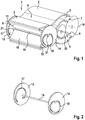
- the in Figure 1 air vent 1 is intended for installation in a dashboard of a motor vehicle, not shown, for ventilating a passenger compartment of the motor vehicle. It has a rectangular tube-shaped housing 2 with a changing height and, in the exemplary embodiment, a constant width.
- the housing 2 forms an air inlet duct 3 which divides at a branch point 4 into a first air duct 5 and a second air duct 6.
- the housing 2 is drawn without side walls.
- the two air ducts 5, 6, which also have rectangular tubular cross-sections, run in an intended flow direction through the air vent 1 starting from the branch point 4, initially at an angle apart and then again at an angle in the intended flow direction and towards each other.
- the first air duct 5 ends with a first air outlet opening 7 and the second air duct 6 with a second air outlet opening 8.
- the air outlet openings 7, 8 in the exemplary embodiment are spaced from one another, but can also be arranged without a spacing from one another. Air currents flowing in the intended flow direction through the two air channels 5, 6 flow as in FIG Figure 4 can be seen obliquely towards each other, from the two air outlet openings 7, 8 and combine to form a common air flow from the air vent 1.
- the air vent 1 has a pivotable flap as a blocking element 9, 10 for each of the two air ducts 5, 6, namely a first blocking element 9 for the first Air channel 5 and a second locking element for the second air channel 6.
- the two flaps can be pivoted about bearing pins 11, 12, namely a first bearing pin 11 for the first locking element 9 and a second bearing pin 12 for the second locking element 10, which are not in the bearing holes in the side walls of the housing 2 shown are mounted.
- the bearing pins 11, 12, which define the pivot axes of the flaps forming the blocking elements 9, 10, are located on the front edges of the blocking elements 9, 10 in the intended flow direction of the air vent 1
- the first bearing pins 11 of the first locking element 9 are located on an upper side and the second bearing pins 12 of the second locking element 10 are located on an underside of the housing 1.
- the air vent 1 has a cam control 13 with two flat and, in the exemplary embodiment, circular control discs 14, 15, namely a first control disc 14 with a first control cam 16 for the first locking element 9 and a second control disc 15 with a second control cam 17 for the second locking element 10.
- the two control disks 14, 15 are arranged non-rotatably on a shaft 18 so that the two control disks 14, 15 and the two control cams 16, 17 are non-rotatably with one another.
- the shaft 18 with the two control cams 16, 17 having control disks 14, 15 is shown in FIG Figure 2 seen individually.
- the control disks 14, 15 are arranged on the side walls (not shown) of the housing 2 of the air vent 1, the shaft 18 is located in a center between the top and bottom of the housing 1 and is rotatably mounted in the side walls of the housing 1.
- a rotary drive of the control disks 14, 15 takes place in the embodiment by hand by means of a handwheel 19 via an intermediate wheel 20, both of which are rotatably mounted on one of the two side walls of the housing 1 and which roll on one another.
- the handwheel 19 protrudes somewhat over the air outlet openings 7, 8 and, when the air outlet 1 is installed in a dashboard in the intended manner, out of the dashboard.
- the rotary drive of the control disks 14, 15 can also take place by means of a motor, in particular an electric motor (not shown).
- Each of the two locking elements 9, 10 has a laterally protruding pin which, as a control element 21, engages in the control cam 16, 17 of one of the two control disks 15, 16.
- the control cams 16, 17 run in sections in the form of a circular arc concentric to the shaft 18, which defines an axis of rotation of the two control disks 14, 15, i.e. with a constant radius to the shaft 18.
- the control cams 16, 17 run arcuately inwards or outwards, so that by rotating the control disks 14, 15 and with them the control cams 16, 17, the two locking elements 9, 10, which are designed as pivotable flaps, are pivoted.
- the movement of the control elements 21 in the control cams 14, 15 or the movement or rotation of the control cams 16, 17 in relation to the control elements 21 can also be understood as passing through the control cams 16, 17.
- first locking element 9 is inclined from the top to the center of the housing 2 and blocks one of the two air channels 5 and the second locking element 10 inside on the bottom of the Housing 2 of the air vent 1 rests, by rotating the control disks 14, 15, the first locking element 9 pivots upwards inward on the top of the housing 2, so that, as in FIG Figure 4 to see that both air channels 5, 6 are open.
- first control disk 14 in the viewing direction is transparent and its first control cams 16 are drawn with broken lines.
- the intermediate wheel 20 and the hand wheel 19 are in Figures 3 to 6 not drawn.
- control disks 14, 15 If the control disks 14, 15 are rotated further, it pivots, as in Figure 5 to see that the second blocking element 10 upwards and blocks the second air duct 6.
- the first blocking element 9 remains inside on the top of the housing 2, so that the associated first air duct 5 remains open. If the control disks 14, 15 are rotated even further, the first blocking element 9 again pivots obliquely inward, so that both air channels 5, 6 are blocked and no air flows through the air vent 1.
- the locking elements 9, 10 can be arranged differently.
- the Figures 7 and 8 show two examples: In Figure 7 the bearing pins 11, 12 of the locking elements 9, 10 are located on the rear edges of the locking elements 9, 10 in the intended flow direction through the air vent 1 and in a middle between the top and the bottom of the housing 2.
- the control elements 21 are located on the the front edges of the blocking elements 9, 10 in the intended flow direction.
- To open the two air ducts 5, 6, the two blocking elements 9, 10 are pivoted into the center of the housing 2. Otherwise, the air vent 1 works off Figure 7 in the same way as the air vent 1 Figures 1 to 6 and reference is made to the explanations above.
- the locking elements 9, 10 are pivotably mounted in their centers and in the centers of the two air channels 5, 6.
- the control elements 21 can be arranged on the front or rear edges of the blocking elements 9, 10 in the flow direction.
- the function shown in FIG Figure 8 curve control 13 not shown as to Figures 1 to 6 explained.
- the two blocking elements 9, 10 are arranged in the region of the branch point 4 of the air inlet duct 3 in the two air ducts 5, 6 and thus at the beginning of the air ducts 5, 6. However, they can also be arranged further back in the air ducts 5, 6 at any point between their beginning and their ends on the air outlet openings 7, 8 (not shown).
- control disks 14, 15 with the control cams 16, 17, the hand wheel 19 and the intermediate wheel 20 are shown in FIG Figures 7 and 8 not drawn.
Description
Die Erfindung betrifft einen Luftausströmer mit den Merkmalen des Oberbegriffs des Anspruchs 1. Der Luftausströmer ist zu einer Belüftung eines Fahrgastraums eines Kraftwagens mit kalter oder warmer Luft vorgesehen und wird typischerweise in ein Armaturenbrett so eingebaut, dass Luftaustrittsöffnungen des Luftausströmers bündig mit dem Armaturenbrett sind. Andere Verwendungen des Luftausströmers sind nicht ausgeschlossen.The invention relates to an air vent with the features of the preamble of claim 1. The air vent is provided to ventilate a passenger compartment of a motor vehicle with cold or warm air and is typically installed in a dashboard so that air outlet openings of the air vent are flush with the dashboard. Other uses of the air vent are not excluded.
Die französische Patentanmeldung
Aus der Offenlegungsschrift
Weitere Luftausströmer sind aus den Patentanmeldungen
In einer Durchströmungsrichtung durch den aus der französischen Patentanmeldung
Aufgabe der Erfindung ist, einen Luftausströmer mit einer vereinfachten Steuermechanik vorzuschlagen.The object of the invention is to propose an air vent with a simplified control mechanism.
Diese Aufgabe wird erfindungsgemäß durch die Merkmale des Anspruchs 1 gelöst. Der erfindungsgemäße Luftausströmer weist zwei Luftkanäle mit jeweils einer Luftaustrittsöffnung auf. Denkbar ist auch, dass ein oder beide Luftkanäle mehrere Luftaustrittsöffnungen aufweisen. Die Luftaustrittsöffnungen können unmittelbar oder mit Abstand neben- bzw. übereinander angeordnet sein. Zu den Luftaustrittsöffnungen hin verlaufen die beiden Luftkanäle schräg aufeinander zu, so dass Luftströme, die die beiden Luftkanäle durchströmen und durch die Luftaustrittsöffnungen ausströmen, schräg aufeinander zu und zusammenströmen und sich zu einem Luftstrom vereinigen. Ist die Luftmenge in einem Luftkanal größer, lenkt das den vereinigten Luftstrom aus dem Luftausströmer nach den Luftaustrittsöffnungen schräg in die entsprechende Richtung.This object is achieved according to the invention by the features of claim 1. The air vent according to the invention has two air ducts, each with an air outlet opening. It is also conceivable that one or both air ducts have several air outlet openings. The air outlet openings can be arranged directly or at a distance next to or above one another. Towards the air outlet openings, the two air ducts run obliquely towards one another, so that air flows that flow through the two air ducts and flow out through the air outlet openings flow towards one another and converge obliquely and combine to form an air flow. If the amount of air in an air duct is greater, this directs the combined air flow from the air vent to the air outlet openings obliquely in the corresponding direction.
Zu einer Steuerung der Luftmengen in den beiden Luftkanälen und damit zum Lenken des vereinigten Luftstroms aus dem Luftausströmer nach den Luftaustrittsöffnungen weist der erfindungsgemäße Luftausströmer für jeden Luftkanal ein bewegliches Sperrelement auf. Der Luftausströmer kann auch mehrere Sperrelemente für einen oder beide Luftkanäle aufweisen. Insbesondere sind die Sperrelemente schwenkbar, vorzugsweise sind sie schwenkbare Klappen. Die Sperrelemente können in einer vorgesehenen Durchströmungsrichtung vor bzw. an einem Anfang der beiden Luftkanäle, also im Bereich der Verzweigungsstelle, an der sich der Luftkanal in die beiden Luftkanäle teilt, oder in den beiden Luftkanälen angeordnet sein. Die Sperrelemente können an einem Anfang an grundsätzlich beliebiger Stelle zwischen dem Anfang und einem Ende oder am Ende der Luftkanäle angeordnet sein. Durch einzelnes oder gemeinsames Bewegen der Sperrelemente lassen sich Luftdurchtrittsquerschnitte der beiden Luftkanäle einzeln oder gemeinsam ändern, wobei durch gemeinsames Bewegen der Sperrelemente die Luftdurchtrittsquerschnitte gemeinsam vergrößert und verkleinert und/oder der Luftdurchtrittsquerschnitt eines Luftkanals vergrößert und der Luftdurchtrittsquerschnitt des anderen Luftkanals verkleinert werden kann.To control the air quantities in the two air ducts and thus to direct the combined air flow from the air vent to the air outlet openings, the air vent according to the invention has a movable locking element for each air duct. The air vent can also have several blocking elements for one or both air ducts. In particular, the locking elements are pivotable, preferably they are pivotable flaps. The blocking elements can be arranged in an intended flow direction in front of or at a start of the two air channels, ie in the area of the branching point at which the air channel divides into the two air channels, or in the two air channels. The blocking elements can be arranged at a beginning at any point between the beginning and an end or at the end of the air ducts. By moving the blocking elements individually or together, the air passage cross-sections of the two air ducts can be changed individually or together, whereby by moving the blocking elements together, the air passage cross-sections can be jointly increased and decreased and / or the air passage cross-section of one air duct can be increased and the air passage cross-section of the other air duct reduced.
Zum Bewegen der Sperrelemente, was auch als Steuern der Sperrelemente und der die beiden Luftkanäle durchströmenden Luftmengen aufgefasst werden kann, weist der erfindungsgemäße Luftausströmer eine Kurvensteuerung mit einer drehbaren Steuerscheibe mit einer Steuerkurve für ein zugeordnetes Sperrelement auf. Die Steuerkurven der Sperrelemente der beiden Luftkanäle sind verschieden, der Luftausströmer weist (mindestens) zwei Steuerkurven auf. Die Steuerscheibe kann beide Steuerkurven aufweisen oder es sind mehrere Steuerscheiben vorhanden. Die Kurvensteuerung kann als eine Kurvensteuerung, die beide Steuerkurven umfasst, oder als zwei Kurvensteuerungen mit jeweils einer Steuerkurve aufgefasst werden. Bei einer Drehung der Steuerscheibe/n werden die Steuerkurven durchlaufen, beispielsweise bewegen sich Steuerelemente der Sperrelemente, die mit den Steuerkurven zusammenwirken, bei der Drehung der Steuerscheibe/n entlang der Steuerkurven. Beim Durchlaufen der Steuerkurven durch Drehung der Steuerscheibe/n bewegt die Kurvensteuerung die Sperrelemente.To move the blocking elements, which can also be understood as controlling the blocking elements and the amounts of air flowing through the two air ducts, the air vent according to the invention has a cam control with a rotatable one Control disk with a cam for an associated locking element. The control curves of the locking elements of the two air ducts are different, the air vent has (at least) two control curves. The control disk can have both control cams or there are several control disks. The cam control can be understood as a cam control that includes both control cams, or as two cam controls, each with one control cam. When the control disk (s) is rotated, the control cams are traversed; for example, control elements of the locking elements that interact with the control cams move along the control cams when the control disk (s) are rotated. When running through the control cams by turning the control disk (s), the cam control moves the locking elements.
Eine Ausgestaltung der Erfindung sieht Steuerelemente an den Sperrelementen vor, die mit der zugeordneten Steuerkurven zusammenwirken. Die Steuerelemente sind beispielsweise Zapfen oder Nasen, die an der Steuerkurve anliegen oder in die Steuerkurve eingreifen. Bei der Drehung der Steuerkurven durch Drehung der Steuerscheibe/n bewegen sich die Steuerelemente an den Steuerkurven entlang, wobei sich tatsächlich die Steuerkurven bewegen. Diese Bewegung der Steuerelemente entlang der Steuerkurven bzw. umgekehrt der Steuerkurven entlang der Steuerelemente kann auch als "Durchlaufen" der Steuerkurven aufgefasst werden. In kreisbogenförmigen Abschnitten der Steuerkurven konzentrisch, das heißt mit gleichbleibendem Radius um eine Drehachse der Steuerscheibe/n herum, werden die Sperrelemente nicht bewegt.One embodiment of the invention provides control elements on the locking elements that interact with the associated control cams. The control elements are, for example, pegs or noses that rest on the control cam or engage in the control cam. When the control cams are rotated by turning the control disk (s), the control elements move along the control cams, and the control cams actually move. This movement of the control elements along the control cams or, conversely, the control cams along the control elements can also be understood as "running through" the control cams. The locking elements are not moved in circular arc-shaped sections of the control cams concentrically, that is to say with a constant radius around an axis of rotation of the control disk (s).
Bewegt werden die Sperrelemente in solchen Abschnitten der Steuerkurven, in denen sich die Steuerkurven von der/den Drehachse/n der Steuerscheibe/n entfernen oder sich der/den Drehachse/n nähern.The locking elements are moved in those sections of the control cams in which the control cams move away from the axis of rotation (s) of the control disk (s) or approach the axis of rotation (s).
Eine Ausgestaltung der Erfindung sieht Steuerkurven mit gemeinsam durchlaufenen Abschnitten vor, die ein Sperrelement bewegen und das andere Sperrelement nicht, und/oder gemeinsam durchlaufene Abschnitte, die beide Sperrelemente bewegen. Es können Abschnitte, die beide Sperrelemente gleichsinnig und/oder Abschnitte, die beide Sperrelemente gegensinnig bewegen, vorhanden sein. Dabei soll "gleichsinnig" als Verkleinern oder Vergrößern der Luftdurchtrittsquerschnitte beider Luftkanäle und "gegensinnig" als Vergrößern des Luftdurchtrittsquerschnitts eines und gleichzeitiges Verkleinern des Luftdurchtrittsquerschnitts des anderen Luftkanals verstanden werden.An embodiment of the invention provides control cams with jointly traversed sections that move one locking element and not the other locking element, and / or jointly traversed sections that move both locking elements. There can be sections that move both locking elements in the same direction and / or sections that move both locking elements in opposite directions. "In the same direction" is to be understood as reducing or increasing the air passage cross-sections of both air ducts and "in opposite directions" as increasing the air passage cross section of one and simultaneously reducing the air passage cross section of the other air duct.
Vorzugsweise sind die Steuerkurven drehfest miteinander, wofür eine Ausgestaltung der Erfindung zwei Steuerscheiben mit jeweils einer Steuerkurve aufweist, denen jeweils ein Sperrelement zugeordnet ist.The control cams are preferably rotationally fixed to one another, for which purpose one embodiment of the invention has two control disks, each with a control cam, each of which is assigned a locking element.
Die Erfindung wird nachfolgend anhand in der Zeichnung dargestellter Ausführungsbeispiele näher erläutert. Es zeigen:
- Figur 1
- ein erstes Ausführungsbeispiel eines erfindungsgemäßen Luftausströmers in einer perspektivischen und teilweise aufgeschnittenen Darstellung;
Figur 2- Steuerscheiben einer Kurvensteuerung des Luftausströmers aus
Figur 1 ; Figuren 3 bis 6- den Luftausströmer aus
Figur 1 mit Sperrelementen in verschiedenen Stellungen in einer Seitenansicht; und Figuren 7 und 8- als weitere Ausführungsbeispiele den Luftausströmer aus
Figur 1 mit anders angeordneten Sperrelementen in Seitenansicht.
- Figure 1
- a first embodiment of an air vent according to the invention in a perspective and partially cut-away illustration;
- Figure 2
- Control discs of a cam control of the air vent
Figure 1 ; - Figures 3 to 6
- the air vent
Figure 1 with locking elements in different positions in a side view; and - Figures 7 and 8
- as further exemplary embodiments, the air vent
Figure 1 with differently arranged locking elements in side view.
Die Figuren sind vereinfachte und schematisierte Darstellungen.The figures are simplified and schematic representations.
Der in
An der Verzweigungsstelle 4, an der sich der Lufteintrittskanal 3 in die beiden Luftkanäle 5, 6 teilt, weist der Luftausströmer 1 für jeden der beiden Luftkanäle 5, 6 eine schwenkbare Klappe als Sperrelement 9, 10 auf, nämlich ein erstes Sperrlement 9 für den ersten Luftkanal 5 und ein zweites Sperrelement für den zweiten Luftkanal 6. Die beiden Klappen sind um Lagerzapfen 11, 12 schwenkbar, nämlich einem ersten Lagerzapfen 11 für das erste Sperrelement 9 und einem zweiten Lagerzapfen 12 für das zweite Sperrelement 10, die in Lagerlöchern in den nicht dargestellten Seitenwänden des Gehäuses 2 gelagert sind. In
Zum Schwenken der Sperrelemente 5, 6 weist der erfindungsgemäße Luftausströmer 1 eine Kurvensteuerung 13 mit zwei ebenen und im Ausführungsbeispiel kreisförmigen Steuerscheiben 14, 15 auf, nämlich einer ersten Steuerscheibe 14 mit einer ersten Steuerkurve 16 für das erste Sperrelement 9 und einer zweiten Steuerscheibe 15 mit einer zweiten Steuerkurve 17 für das zweite Sperrelement 10. Die beiden Steuerscheiben 14, 15 sind drehfest auf einer Welle 18 angeordnet, so dass die beiden Steuerscheiben 14, 15 und die beiden Steuerkurven 16, 17 drehfest miteinander sind. Die Welle 18 mit den beiden die Steuerkurven 16, 17 aufweisenden Steuerscheiben 14, 15 ist in
Ein Drehantrieb der Steuerscheiben 14, 15 erfolgt im Ausführungsbeispiel von Hand mittels eines Handrads 19 über ein Zwischenrad 20, die beide drehbar an einer der beiden Seitenwände des Gehäuses 1 gelagert sind und die aufeinander wälzen. Das Handrad 19 steht etwas über die Luftaustrittsöffnungen 7, 8 über und bei in vorgesehener Weise in ein Armaturenbrett eingebautem Luftausströmer 1 aus dem Armaturenbrett vor. Der Drehantrieb der Steuerscheiben 14, 15 kann auch mittels eines Motors, insbesondere eines Elektromotors erfolgen (nicht dargestellt).A rotary drive of the
Jedes der beiden Sperrelemente 9, 10 weist einen seitlich abstehenden Zapfen auf, der als Steuerelement 21 in die Steuerkurve 16, 17 einer der beiden Steuerscheiben 15, 16 eingreift. Die Steuerkurven 16, 17 verlaufen abschnittsweise kreisbogenförmig konzentrisch zur Welle 18, die eine Drehachse der beiden Steuerscheiben 14, 15 definiert, das heißt mit konstantem Radius zur Welle 18. Auf anderen Abschnitten verlaufen die Steuerkurven 16, 17 bogenförmig nach innen bzw. nach außen, so dass durch Drehung der Steuerscheiben 14, 15 und mit ihnen der Steuerkurven 16, 17 die beiden als schwenkbare Klappen ausgebildeten Sperrelemente 9, 10 geschwenkt werden. Die Bewegung der Steuerelemente 21 in den Steuerkurven 14, 15 bzw. die Bewegung bzw. Drehung der Steuerkurven 16, 17 in Bezug zu den Steuerelementen 21 kann auch als Durchlaufen der Steuerkurven 16, 17 aufgefasst werden.Each of the two
Ausgehend von einer in
Bei einem Weiterdrehen der Steuerscheiben 14, 15 schwenkt, wie in
Die Sperrelemente 9, 10 können anders angeordnet sein. Die
In
Die Steuerscheiben 14, 15 mit den Steuerkurven 16, 17, das Handrad 19 und das Zwischenrad 20 sind in
- 11
- LuftausströmerAir vents
- 22
- Gehäusecasing
- 33
- LufteintrittskanalAir inlet duct
- 44th
- VerzweigungsstelleBranching point
- 55
- erster Luftkanalfirst air duct
- 66
- zweiter Luftkanalsecond air duct
- 77th
- erste Luftaustrittsöffnungfirst air outlet opening
- 88th
- zweite Luftaustrittsöffnungsecond air outlet opening
- 99
- erstes Sperrelementfirst locking element
- 1010
- zweites Sperrelementsecond locking element
- 1111
- erster Lagerzapfenfirst bearing journal
- 1212th
- zweiter Lagerzapfensecond bearing journal
- 1313
- KurvensteuerungCurve control
- 1414th
- erste Steuerscheibefirst control disk
- 1515th
- zweite Steuerscheibesecond control disk
- 1616
- erste Steuerkurvefirst control curve
- 1717th
- zweite Steuerkurvesecond control curve
- 1818th
- Wellewave
- 1919th
- HandradHandwheel
- 2020th
- ZwischenradIntermediate gear
- 2121st
- SteuerelementControl
Claims (6)
- Air vent (1), having two air ducts (5, 6) which each have an air-outlet opening (7, 8) and which run obliquely towards the air-outlet openings (7, 8) in an intended direction of airflow through the air ducts (5, 6) and towards one another, so that air currents flowing out of the air ducts (5, 6) through the two air-outlet openings (7, 8) converge to form a common air current, and having for each air duct (5, 6) a movable blocking element (9, 10) with which air-flow cross-sections of the two air ducts (5, 6) can be individually reduced in size, characterised in that the air vent (1) has for each blocking element (9, 10) a cam control means (13) having a rotatable control disc (14, 15) with a control cam (16, 17) for the associated blocking element (9, 10), with which control cam the respective blocking element (9,10) is movable, the control cams (16, 17) being traversed on rotation of the control disc (14, 15).
- Air vent(1) according to claim 1, characterised in that the blocking elements (9, 10) have control elements (21) which co-operate with the associated control cam (16, 17) and which, on rotation of the control disc (14, 15), move along the control cams (16, 17) so that the blocking elements (9, 10) are moved.
- Air vent(1) according to claim 1 or 2, characterised in that the control cams (16, 17) have jointly traversed sections with which they move one blocking element (9, 10) while another blocking element (10, 9) is stationary, and/or the control cams (16, 17) have jointly traversed sections in which they move both blocking elements (9, 10) in the same direction, and/or the control cams (16, 17) have jointly traversed sections in which they move both blocking elements (9, 10) in opposite directions.
- Air vent (1) according to one or more of claims 1 to 3, characterised in that the control cams (16, 17) are fixed against rotation relative to one another.
- Air vent (1) according to one or more of the preceding claims, characterised in that the air vent (1) has two coaxial control discs (14, 15), of which each control disc (14, 15) has a control cam (16, 17) for the associated blocking element (9, 10).
- Air vent (1) according to one or more of the preceding claims, characterised in that the blocking elements (9, 10) are pivotable, especially being pivotable flaps.
Applications Claiming Priority (1)
| Application Number | Priority Date | Filing Date | Title |
|---|---|---|---|
| DE102018105747.4A DE102018105747A1 (en) | 2018-03-13 | 2018-03-13 | air vents |
Publications (2)
| Publication Number | Publication Date |
|---|---|
| EP3546258A1 EP3546258A1 (en) | 2019-10-02 |
| EP3546258B1 true EP3546258B1 (en) | 2020-09-30 |
Family
ID=65598488
Family Applications (1)
| Application Number | Title | Priority Date | Filing Date |
|---|---|---|---|
| EP19159325.0A Active EP3546258B1 (en) | 2018-03-13 | 2019-02-26 | Air vent |
Country Status (2)
| Country | Link |
|---|---|
| EP (1) | EP3546258B1 (en) |
| DE (1) | DE102018105747A1 (en) |
Families Citing this family (4)
| Publication number | Priority date | Publication date | Assignee | Title |
|---|---|---|---|---|
| DE102019107446A1 (en) * | 2019-03-22 | 2020-09-24 | Bayerische Motoren Werke Aktiengesellschaft | Air vent for a motor vehicle and motor vehicle with such an air vent |
| DE102019120516A1 (en) | 2019-07-30 | 2021-02-04 | Fischer Automotive Systems Gmbh & Co. Kg | Air vents |
| CN111497568B (en) * | 2020-04-08 | 2023-03-21 | 浙江吉利汽车研究院有限公司 | Switching device of channel, air conditioning system and automobile |
| DE102020131095A1 (en) * | 2020-11-24 | 2022-05-25 | Novares Löhne GmbH | ventilation device |
Family Cites Families (5)
| Publication number | Priority date | Publication date | Assignee | Title |
|---|---|---|---|---|
| FR2760694B1 (en) * | 1997-03-12 | 1999-04-30 | Bourbon Automobile Sa | MOUTH FOR THE FLOW OF A FLUID |
| DE202013012285U1 (en) * | 2013-05-29 | 2016-01-18 | Faurecia Innenraum Systeme Gmbh | air vents |
| FR3054491B1 (en) | 2016-07-29 | 2018-07-20 | Peugeot Citroen Automobiles Sa | AERATOR FOR A MOTOR VEHICLE WITH IMPROVED COMPACITY. |
| DE102016116358A1 (en) * | 2016-09-01 | 2018-03-01 | Fischer Automotive Systems Gmbh & Co. Kg | air vents |
| DE102017111011A1 (en) * | 2017-05-19 | 2017-07-27 | Dr. Schneider Kunststoffwerke Gmbh | air vents |
-
2018
- 2018-03-13 DE DE102018105747.4A patent/DE102018105747A1/en not_active Withdrawn
-
2019
- 2019-02-26 EP EP19159325.0A patent/EP3546258B1/en active Active
Non-Patent Citations (1)
| Title |
|---|
| None * |
Also Published As
| Publication number | Publication date |
|---|---|
| EP3546258A1 (en) | 2019-10-02 |
| DE102018105747A1 (en) | 2019-09-19 |
Similar Documents
| Publication | Publication Date | Title |
|---|---|---|
| EP3546258B1 (en) | Air vent | |
| DE102017113906B4 (en) | air vents | |
| EP3530506B1 (en) | Air vent | |
| DE102008050180B4 (en) | air outlet nozzle | |
| EP3290245A1 (en) | Air vent | |
| EP1800918B1 (en) | Air nozzle with vortex air flow | |
| DE102017120417A1 (en) | Air vents with adjustable air outlet direction, in particular flat or joint vents | |
| DE102018205881B3 (en) | Air vents for a vehicle | |
| DE102005027746A1 (en) | Air outlet for passenger cabin of vehicle, comprises transversal bridges with triangular cross sections and movable elements with curved rear areas | |
| EP3321114A1 (en) | Air vent | |
| EP3231647B1 (en) | Air vent | |
| DE102016116356A1 (en) | air vents | |
| DE19739652B4 (en) | aerator | |
| DE202017102616U1 (en) | Air vents for use in a vehicle | |
| DE102018104048A1 (en) | air vents | |
| DE102007018022A1 (en) | Air nozzle, in particular, for guiding an air stream in ventilation and air-conditioning units in motor vehicles comprises a twister unit with a central body carrying twister elements | |
| DE102014100441A1 (en) | Air deflector for an air vent | |
| EP1270286B1 (en) | Air directing device especially for a vehicle | |
| DE102019131554B4 (en) | Air outlet device for the outlet of an air flow | |
| DE102007037273A1 (en) | Air nozzle for ventilation of a vehicle interior | |
| DE19854795C1 (en) | Ventilator for motor vehicle has branch passage controlled by rotary segment to control flow through main and secondary passages | |
| EP0841202B1 (en) | Heating or air conditioning installation | |
| DE19816013A1 (en) | Airflow distributor for a motor vehicle interior | |
| DE202004015522U1 (en) | Louver system for car heater outlet has control levers attached to louvers in such way that ends which are near outlet can be positioned closer to each other than opposite ends | |
| DE102004004427B4 (en) | exhaust nozzle |
Legal Events
| Date | Code | Title | Description |
|---|---|---|---|
| PUAI | Public reference made under article 153(3) epc to a published international application that has entered the european phase |
Free format text: ORIGINAL CODE: 0009012 |
|
| STAA | Information on the status of an ep patent application or granted ep patent |
Free format text: STATUS: THE APPLICATION HAS BEEN PUBLISHED |
|
| AK | Designated contracting states |
Kind code of ref document: A1 Designated state(s): AL AT BE BG CH CY CZ DE DK EE ES FI FR GB GR HR HU IE IS IT LI LT LU LV MC MK MT NL NO PL PT RO RS SE SI SK SM TR |
|
| AX | Request for extension of the european patent |
Extension state: BA ME |
|
| STAA | Information on the status of an ep patent application or granted ep patent |
Free format text: STATUS: REQUEST FOR EXAMINATION WAS MADE |
|
| 17P | Request for examination filed |
Effective date: 20200227 |
|
| RBV | Designated contracting states (corrected) |
Designated state(s): AL AT BE BG CH CY CZ DE DK EE ES FI FR GB GR HR HU IE IS IT LI LT LU LV MC MK MT NL NO PL PT RO RS SE SI SK SM TR |
|
| GRAP | Despatch of communication of intention to grant a patent |
Free format text: ORIGINAL CODE: EPIDOSNIGR1 |
|
| STAA | Information on the status of an ep patent application or granted ep patent |
Free format text: STATUS: GRANT OF PATENT IS INTENDED |
|
| INTG | Intention to grant announced |
Effective date: 20200519 |
|
| GRAS | Grant fee paid |
Free format text: ORIGINAL CODE: EPIDOSNIGR3 |
|
| GRAA | (expected) grant |
Free format text: ORIGINAL CODE: 0009210 |
|
| STAA | Information on the status of an ep patent application or granted ep patent |
Free format text: STATUS: THE PATENT HAS BEEN GRANTED |
|
| AK | Designated contracting states |
Kind code of ref document: B1 Designated state(s): AL AT BE BG CH CY CZ DE DK EE ES FI FR GB GR HR HU IE IS IT LI LT LU LV MC MK MT NL NO PL PT RO RS SE SI SK SM TR |
|
| REG | Reference to a national code |
Ref country code: CH Ref legal event code: EP Ref country code: GB Ref legal event code: FG4D Free format text: NOT ENGLISH |
|
| REG | Reference to a national code |
Ref country code: DE Ref legal event code: R096 Ref document number: 502019000252 Country of ref document: DE Ref country code: AT Ref legal event code: REF Ref document number: 1318447 Country of ref document: AT Kind code of ref document: T Effective date: 20201015 |
|
| REG | Reference to a national code |
Ref country code: IE Ref legal event code: FG4D Free format text: LANGUAGE OF EP DOCUMENT: GERMAN |
|
| PG25 | Lapsed in a contracting state [announced via postgrant information from national office to epo] |
Ref country code: NO Free format text: LAPSE BECAUSE OF FAILURE TO SUBMIT A TRANSLATION OF THE DESCRIPTION OR TO PAY THE FEE WITHIN THE PRESCRIBED TIME-LIMIT Effective date: 20201230 Ref country code: SE Free format text: LAPSE BECAUSE OF FAILURE TO SUBMIT A TRANSLATION OF THE DESCRIPTION OR TO PAY THE FEE WITHIN THE PRESCRIBED TIME-LIMIT Effective date: 20200930 Ref country code: GR Free format text: LAPSE BECAUSE OF FAILURE TO SUBMIT A TRANSLATION OF THE DESCRIPTION OR TO PAY THE FEE WITHIN THE PRESCRIBED TIME-LIMIT Effective date: 20201231 Ref country code: FI Free format text: LAPSE BECAUSE OF FAILURE TO SUBMIT A TRANSLATION OF THE DESCRIPTION OR TO PAY THE FEE WITHIN THE PRESCRIBED TIME-LIMIT Effective date: 20200930 Ref country code: HR Free format text: LAPSE BECAUSE OF FAILURE TO SUBMIT A TRANSLATION OF THE DESCRIPTION OR TO PAY THE FEE WITHIN THE PRESCRIBED TIME-LIMIT Effective date: 20200930 Ref country code: BG Free format text: LAPSE BECAUSE OF FAILURE TO SUBMIT A TRANSLATION OF THE DESCRIPTION OR TO PAY THE FEE WITHIN THE PRESCRIBED TIME-LIMIT Effective date: 20201230 |
|
| PG25 | Lapsed in a contracting state [announced via postgrant information from national office to epo] |
Ref country code: LV Free format text: LAPSE BECAUSE OF FAILURE TO SUBMIT A TRANSLATION OF THE DESCRIPTION OR TO PAY THE FEE WITHIN THE PRESCRIBED TIME-LIMIT Effective date: 20200930 Ref country code: RS Free format text: LAPSE BECAUSE OF FAILURE TO SUBMIT A TRANSLATION OF THE DESCRIPTION OR TO PAY THE FEE WITHIN THE PRESCRIBED TIME-LIMIT Effective date: 20200930 |
|
| REG | Reference to a national code |
Ref country code: NL Ref legal event code: MP Effective date: 20200930 |
|
| REG | Reference to a national code |
Ref country code: LT Ref legal event code: MG4D |
|
| PG25 | Lapsed in a contracting state [announced via postgrant information from national office to epo] |
Ref country code: SM Free format text: LAPSE BECAUSE OF FAILURE TO SUBMIT A TRANSLATION OF THE DESCRIPTION OR TO PAY THE FEE WITHIN THE PRESCRIBED TIME-LIMIT Effective date: 20200930 Ref country code: LT Free format text: LAPSE BECAUSE OF FAILURE TO SUBMIT A TRANSLATION OF THE DESCRIPTION OR TO PAY THE FEE WITHIN THE PRESCRIBED TIME-LIMIT Effective date: 20200930 Ref country code: EE Free format text: LAPSE BECAUSE OF FAILURE TO SUBMIT A TRANSLATION OF THE DESCRIPTION OR TO PAY THE FEE WITHIN THE PRESCRIBED TIME-LIMIT Effective date: 20200930 Ref country code: CZ Free format text: LAPSE BECAUSE OF FAILURE TO SUBMIT A TRANSLATION OF THE DESCRIPTION OR TO PAY THE FEE WITHIN THE PRESCRIBED TIME-LIMIT Effective date: 20200930 Ref country code: PT Free format text: LAPSE BECAUSE OF FAILURE TO SUBMIT A TRANSLATION OF THE DESCRIPTION OR TO PAY THE FEE WITHIN THE PRESCRIBED TIME-LIMIT Effective date: 20210201 Ref country code: RO Free format text: LAPSE BECAUSE OF FAILURE TO SUBMIT A TRANSLATION OF THE DESCRIPTION OR TO PAY THE FEE WITHIN THE PRESCRIBED TIME-LIMIT Effective date: 20200930 |
|
| PG25 | Lapsed in a contracting state [announced via postgrant information from national office to epo] |
Ref country code: AL Free format text: LAPSE BECAUSE OF FAILURE TO SUBMIT A TRANSLATION OF THE DESCRIPTION OR TO PAY THE FEE WITHIN THE PRESCRIBED TIME-LIMIT Effective date: 20200930 Ref country code: ES Free format text: LAPSE BECAUSE OF FAILURE TO SUBMIT A TRANSLATION OF THE DESCRIPTION OR TO PAY THE FEE WITHIN THE PRESCRIBED TIME-LIMIT Effective date: 20200930 Ref country code: IS Free format text: LAPSE BECAUSE OF FAILURE TO SUBMIT A TRANSLATION OF THE DESCRIPTION OR TO PAY THE FEE WITHIN THE PRESCRIBED TIME-LIMIT Effective date: 20210130 Ref country code: PL Free format text: LAPSE BECAUSE OF FAILURE TO SUBMIT A TRANSLATION OF THE DESCRIPTION OR TO PAY THE FEE WITHIN THE PRESCRIBED TIME-LIMIT Effective date: 20200930 |
|
| PG25 | Lapsed in a contracting state [announced via postgrant information from national office to epo] |
Ref country code: SK Free format text: LAPSE BECAUSE OF FAILURE TO SUBMIT A TRANSLATION OF THE DESCRIPTION OR TO PAY THE FEE WITHIN THE PRESCRIBED TIME-LIMIT Effective date: 20200930 Ref country code: NL Free format text: LAPSE BECAUSE OF FAILURE TO SUBMIT A TRANSLATION OF THE DESCRIPTION OR TO PAY THE FEE WITHIN THE PRESCRIBED TIME-LIMIT Effective date: 20200930 |
|
| REG | Reference to a national code |
Ref country code: DE Ref legal event code: R097 Ref document number: 502019000252 Country of ref document: DE |
|
| PLBE | No opposition filed within time limit |
Free format text: ORIGINAL CODE: 0009261 |
|
| STAA | Information on the status of an ep patent application or granted ep patent |
Free format text: STATUS: NO OPPOSITION FILED WITHIN TIME LIMIT |
|
| PG25 | Lapsed in a contracting state [announced via postgrant information from national office to epo] |
Ref country code: DK Free format text: LAPSE BECAUSE OF FAILURE TO SUBMIT A TRANSLATION OF THE DESCRIPTION OR TO PAY THE FEE WITHIN THE PRESCRIBED TIME-LIMIT Effective date: 20200930 |
|
| 26N | No opposition filed |
Effective date: 20210701 |
|
| PG25 | Lapsed in a contracting state [announced via postgrant information from national office to epo] |
Ref country code: MC Free format text: LAPSE BECAUSE OF FAILURE TO SUBMIT A TRANSLATION OF THE DESCRIPTION OR TO PAY THE FEE WITHIN THE PRESCRIBED TIME-LIMIT Effective date: 20200930 |
|
| REG | Reference to a national code |
Ref country code: BE Ref legal event code: MM Effective date: 20210228 |
|
| PG25 | Lapsed in a contracting state [announced via postgrant information from national office to epo] |
Ref country code: IT Free format text: LAPSE BECAUSE OF FAILURE TO SUBMIT A TRANSLATION OF THE DESCRIPTION OR TO PAY THE FEE WITHIN THE PRESCRIBED TIME-LIMIT Effective date: 20200930 Ref country code: LU Free format text: LAPSE BECAUSE OF NON-PAYMENT OF DUE FEES Effective date: 20210226 |
|
| PG25 | Lapsed in a contracting state [announced via postgrant information from national office to epo] |
Ref country code: SI Free format text: LAPSE BECAUSE OF FAILURE TO SUBMIT A TRANSLATION OF THE DESCRIPTION OR TO PAY THE FEE WITHIN THE PRESCRIBED TIME-LIMIT Effective date: 20200930 |
|
| PG25 | Lapsed in a contracting state [announced via postgrant information from national office to epo] |
Ref country code: FR Free format text: LAPSE BECAUSE OF NON-PAYMENT OF DUE FEES Effective date: 20210228 Ref country code: IE Free format text: LAPSE BECAUSE OF NON-PAYMENT OF DUE FEES Effective date: 20210226 |
|
| PG25 | Lapsed in a contracting state [announced via postgrant information from national office to epo] |
Ref country code: IS Free format text: LAPSE BECAUSE OF FAILURE TO SUBMIT A TRANSLATION OF THE DESCRIPTION OR TO PAY THE FEE WITHIN THE PRESCRIBED TIME-LIMIT Effective date: 20210130 |
|
| PG25 | Lapsed in a contracting state [announced via postgrant information from national office to epo] |
Ref country code: BE Free format text: LAPSE BECAUSE OF NON-PAYMENT OF DUE FEES Effective date: 20210228 |
|
| REG | Reference to a national code |
Ref country code: CH Ref legal event code: PL |
|
| PG25 | Lapsed in a contracting state [announced via postgrant information from national office to epo] |
Ref country code: LI Free format text: LAPSE BECAUSE OF NON-PAYMENT OF DUE FEES Effective date: 20220228 Ref country code: CH Free format text: LAPSE BECAUSE OF NON-PAYMENT OF DUE FEES Effective date: 20220228 |
|
| PGFP | Annual fee paid to national office [announced via postgrant information from national office to epo] |
Ref country code: DE Payment date: 20220530 Year of fee payment: 5 |
|
| PG25 | Lapsed in a contracting state [announced via postgrant information from national office to epo] |
Ref country code: CY Free format text: LAPSE BECAUSE OF FAILURE TO SUBMIT A TRANSLATION OF THE DESCRIPTION OR TO PAY THE FEE WITHIN THE PRESCRIBED TIME-LIMIT Effective date: 20200930 |
|
| PG25 | Lapsed in a contracting state [announced via postgrant information from national office to epo] |
Ref country code: HU Free format text: LAPSE BECAUSE OF FAILURE TO SUBMIT A TRANSLATION OF THE DESCRIPTION OR TO PAY THE FEE WITHIN THE PRESCRIBED TIME-LIMIT; INVALID AB INITIO Effective date: 20190226 |
|
| GBPC | Gb: european patent ceased through non-payment of renewal fee |
Effective date: 20230226 |
|
| PG25 | Lapsed in a contracting state [announced via postgrant information from national office to epo] |
Ref country code: GB Free format text: LAPSE BECAUSE OF NON-PAYMENT OF DUE FEES Effective date: 20230226 |
|
| PG25 | Lapsed in a contracting state [announced via postgrant information from national office to epo] |
Ref country code: GB Free format text: LAPSE BECAUSE OF NON-PAYMENT OF DUE FEES Effective date: 20230226 |