EP3546146B1 - Dispositif d'épilation - Google Patents
Dispositif d'épilation Download PDFInfo
- Publication number
- EP3546146B1 EP3546146B1 EP18164333.9A EP18164333A EP3546146B1 EP 3546146 B1 EP3546146 B1 EP 3546146B1 EP 18164333 A EP18164333 A EP 18164333A EP 3546146 B1 EP3546146 B1 EP 3546146B1
- Authority
- EP
- European Patent Office
- Prior art keywords
- trimmers
- short hair
- working head
- cutters
- removal device
- Prior art date
- Legal status (The legal status is an assumption and is not a legal conclusion. Google has not performed a legal analysis and makes no representation as to the accuracy of the status listed.)
- Active
Links
- 210000004209 hair Anatomy 0.000 title claims description 206
- 230000009189 diving Effects 0.000 claims description 6
- 239000011888 foil Substances 0.000 description 8
- 239000000835 fiber Substances 0.000 description 4
- 238000009966 trimming Methods 0.000 description 2
- 230000000694 effects Effects 0.000 description 1
- 210000004919 hair shaft Anatomy 0.000 description 1
- 210000003739 neck Anatomy 0.000 description 1
Images


Classifications
-
- B—PERFORMING OPERATIONS; TRANSPORTING
- B26—HAND CUTTING TOOLS; CUTTING; SEVERING
- B26B—HAND-HELD CUTTING TOOLS NOT OTHERWISE PROVIDED FOR
- B26B19/00—Clippers or shavers operating with a plurality of cutting edges, e.g. hair clippers, dry shavers
- B26B19/02—Clippers or shavers operating with a plurality of cutting edges, e.g. hair clippers, dry shavers of the reciprocating-cutter type
- B26B19/04—Cutting heads therefor; Cutters therefor; Securing equipment thereof
- B26B19/048—Complete cutting head being movable
-
- B—PERFORMING OPERATIONS; TRANSPORTING
- B26—HAND CUTTING TOOLS; CUTTING; SEVERING
- B26B—HAND-HELD CUTTING TOOLS NOT OTHERWISE PROVIDED FOR
- B26B19/00—Clippers or shavers operating with a plurality of cutting edges, e.g. hair clippers, dry shavers
- B26B19/02—Clippers or shavers operating with a plurality of cutting edges, e.g. hair clippers, dry shavers of the reciprocating-cutter type
- B26B19/04—Cutting heads therefor; Cutters therefor; Securing equipment thereof
- B26B19/046—Cutters being movable in the cutting head
-
- B—PERFORMING OPERATIONS; TRANSPORTING
- B26—HAND CUTTING TOOLS; CUTTING; SEVERING
- B26B—HAND-HELD CUTTING TOOLS NOT OTHERWISE PROVIDED FOR
- B26B19/00—Clippers or shavers operating with a plurality of cutting edges, e.g. hair clippers, dry shavers
- B26B19/02—Clippers or shavers operating with a plurality of cutting edges, e.g. hair clippers, dry shavers of the reciprocating-cutter type
- B26B19/04—Cutting heads therefor; Cutters therefor; Securing equipment thereof
- B26B19/10—Cutting heads therefor; Cutters therefor; Securing equipment thereof involving two or more different types of reciprocating cutting elements, e.g. a pair of toothed shearing elements combined with a pair of perforated cutting elements or a combined toothed and perforated cutting assembly
- B26B19/105—Cutting heads therefor; Cutters therefor; Securing equipment thereof involving two or more different types of reciprocating cutting elements, e.g. a pair of toothed shearing elements combined with a pair of perforated cutting elements or a combined toothed and perforated cutting assembly with a secondary cutting unit being rotated into an operating position
-
- B—PERFORMING OPERATIONS; TRANSPORTING
- B26—HAND CUTTING TOOLS; CUTTING; SEVERING
- B26B—HAND-HELD CUTTING TOOLS NOT OTHERWISE PROVIDED FOR
- B26B19/00—Clippers or shavers operating with a plurality of cutting edges, e.g. hair clippers, dry shavers
- B26B19/38—Details of, or accessories for, hair clippers, or dry shavers, e.g. housings, casings, grips, guards
- B26B19/3853—Housing or handle
Definitions
- the present invention relates to a hair removal device, in particular an electric shaver, comprising a working head attached to a handle for moving the working head along a skin surface, said working head including at least a two short hair cutters and at least one trimmer neighboring at least one of said short hair cutters, wherein said short hair cutters and said trimmer are movable relative to said handle under a skin contact pressure.
- Hair removal devices such as an electric shaver, epilators, or beard trimmers usually include different types of cutting and trimming devices so as to allow for removing long hairs as well as medium hairs and short hairs and stubbles, as commonly found in men's beards and women's legs.
- Short hair cutters may include a movable cutting blade or undercutter which cooperates with a thin, flexible mesh screen or apertured or perforated foil, wherein such mesh screen or foil may have a rounded, elongated contour and the undercutter may reciprocate under such elongated, rounded contour of the mesh screen along a longitudinal axis thereof.
- rotatory cutter elements which may be driven in an oscillating or a continuous manner and may cooperate with disc-shaped mesh screens covering said rotatory cutter elements.
- the individual hair shafts enter the holes formed in the screen or foil and are cut by the movement of the cutting blades.
- trimmers are provided at the working head, wherein such trimmers may be positioned adjacent to one of the short hair cutters.
- such trimmers may form an elongated block extending along one of the elongated, rounded mesh screens or perforated foils of the short cutters, wherein it is known to have such trimmers in a retracted, non-operative position below the skin contact surface of the short cutters so the trimmer does not contact the skin surface when the short cutters slide along the skin surface.
- Such trimmers may include a cutter bar with a pair of sickle finger bars reciprocating relative to each other, but may also include a foil or cover plate having comparatively larger apertures under which an undercutter with cutting blades may reciprocate or continuously rotate to cut hairs entering the apertures.
- trimmers in a position substantially aligned with and/or substantially on the same height as the skin contact surface of the short hair cutters so as to effect short hair cutting as well as long hair cutting at the same time.
- document US 6317982 B1 discloses an electric shaver with a shaver head including a pair of short cutters and a pair of trimmers with the short cutters being positioned next to each other in the center of the shaver head and the trimmers being positioned at an outer side of the short hair cutters, wherein the trimmers may be moved relative to the short hair cutters into three positions in which the trimmers are retracted below the top surface of the mesh screen of the short hair cutters or substantially aligned with the upper top surface of the short cutters or extended and raised above said top surface of the short cutters.
- document US 2005/0016002 A1 discloses an electric shaver having a shaver head with a pair of short hair cutters arranged in a center portion of the shaver head between a pair of long hair trimmers.
- the shaver head includes a pair of outer cutter frames each of which accommodates a short hair cutter and a long hair trimmer, wherein each of said outer cutter frames is movable relative to the handle and independently of each other.
- each of said outer cutter frames may float relative to the handle and may swing relative to the handle about an axis substantially perpendicular to the longitudinal axis of the short hair cutter block and the long hair trimmer block and also perpendicular to the longitudinal axis of the handle so - in other words - a left end of the elongated trimmer and elongated short hair cutter may rotate into a further projecting position whereas the opposite left end of said short hair cutters and trimmers may rotate into a less projecting position and vice versa. Due to such swingable configuration of the outer cutter frames and the cutters and trimmers accommodated therein, a better adaption to the skin contour is promised when the handle is guided in an orientation not perpendicular to the skin surface.
- the shaver head does not only have a significant width transverse to the sliding direction (along which the working head slides along the skin surface), but also has a significant extension perpendicular to said width and substantially parallel to the sliding direction so it might be that only one or none of the short hair cutters contacts the skin due to the trimmers contacting a heightened portion of the skin contour or only one or none of the trimmers may contact the skin due to the short hair cutters contacting an elevated skin contour portion.
- EP3 300 863 A1 is a prior art document according to Article 54(3) EPC and discloses all features of the preamble portion of claim 1.
- a more particular objective underlying the invention is to provide for an improved working head structure of such hair removal device with improved coexistence of short hair cutters and trimmers with less interference of skin contact of each of said short hair cutters and trimmers.
- Another objective underlying the present invention is to allow for further improved self-adaption of the short hair cutters and trimmers to complex skin contours, in particular to allow for better adjustment of the short hair cutters and trimmers to convex and concave skin contours.
- a hair removal device has an improved working head structure allowing for pivoting movements of at least one trimmer relative to at least one of the multiple short hair cutters about a pivot axis extending substantially parallel to a plane separating the trimmer from the neighboring short hair cutter and substantially parallel to a plane perpendicular to the longitudinal axis of the handle. Due to such pivoting movement of the trimmer relative to at least one of the short hair cutters, both the short hair cutter and the trimmer may contact the skin surface in a substantially perpendicular orientation when the working head slides across a concave contour and/or a convex contour.
- a at least two trimmers and at least two short hair cutters mounted on a pair of support frames pivotably supported relative to each other about a common or a pair of separate pivot axes each parallel to the aforementioned first and second planes between a first pivot position in which said at least two trimmers and said at least two short hair cutters together define a concave skin contact contour, and a second pivot position in which said at least two trimmers and at least two short hair cutters together define a convex skin contact contour.
- Said skin contact contour is in fact defined by the top surfaces of the short hair cutters and trimmers facing away from the handle and/or forming the upper top surface of the hair removal device when considering the handle in an upright position, wherein such skin contact surface of the working head is not necessarily - and is usually not - a smooth, flat surface due to the curved surfaces of the mesh screen of the short hair cutters and the gaps between the separate cutters and trimmers, but nevertheless the surfaces of the short hair cutters and trimmers together define a sort of enveloping surface which may become concave as well as convex, and may become a flat plane in an intermediate configuration between convex and concave, due to the pivoting support of the pair of frames accommodating the trimmers and short hair cutters.
- a very flat, compact structure of the working head can be combined with an improved self-adaption of the working head to varying skin contours. More particularly, an orientation of the trimmers and short hair cutters substantially perpendicular to the skin surface can be achieved to allow hairs to enter the apertures of the cutter foils even when moving the working head over uneven skin contours, wherein on the other hand at least one of the short hair cutters and/or at least one of the trimmers contacts the skin with higher contact pressure whereas another at least one of the short hair cutters and/or trimmers is pressed against the skin with less pressure due to differing leverage arms from the pivot axis, thus achieving high pressure and low pressure cutting at the same time.
- the hair removal device has an improved working head structure allowing for pivoting movements of at least one trimmer relative to at least one of the multiple short hair cutters about a pivot axis extending substantially parallel to a first plane separating the trimmer from the neighboring short hair cutter and substantially parallel to a second plane perpendicular to the longitudinal axis of the handle. Due to such pivoting movement of the trimmer relative to at least one of the short hair cutters, both the short hair cutter and the trimmer may contact the skin surface in a substantially perpendicular orientation when the working head slides across a concave contour and/or a convex contour.
- air of trimmers also includes in the following the alternative of at least one trimmer not limited to an adjacent / pairwise arrangement of one or more trimmers
- a pair of short hair cutters means in the following at least two short hair cutters independent of its arrangement relative to each other mounted on a pair of support frames pivotably supported relative to each other about a common or a pair of separate pivot axes each parallel to the aforementioned first and second planes between a first pivot position in which said pair of trimmers and said pair of short hair cutters together define a concave skin contact contour, and a second pivot position in which said pair of trimmers and pair of short hair cutters together define a convex skin contact contour.
- Said skin contact contour is in fact defined by the top surfaces of the short hair cutters and trimmers facing away from the handle and/or forming the upper top surface of the hair removal device when considering the handle in an upright position, wherein such skin contact surface of the working head is not necessarily - and is usually not - a smooth, flat surface due to the curved surfaces of the mesh screen of the short hair cutters and the gaps between the separate cutters and trimmers, but nevertheless the surfaces of the short hair cutters and trimmers together define a sort of enveloping surface which may become concave as well as convex, and may become a flat plane in an intermediate configuration between convex and concave, due to the pivoting support of the pair of frames accommodating the trimmers and short hair cutters.
- the aforementioned pair of support frames may be pivotably supported about a common pivot axis or, in the alternative, about a pair of separate pivot axes wherein such separate pivot axes may be arranged parallel to each other.
- the common pivot axis or the pair of separate pivot axes may extend parallel to the aforementioned first and second planes in a center portion of the working head and/or between the pairs of short hair cutters and trimmers. More particularly, the common pivot axis and/or the separate pivot axes may extend in a center portion of the working head on opposite sides of which are arranged two cutter and/or trimmer elements each.
- pivot axis of the support frame provides for a balanced, substantially symmetrical arrangement of the working head and its short hair cutters and trimmers in terms of "two-and-two" on both sides of the pivot axis, thereby achieving a smooth self-adaption to various skin contours irrespective of the stroke direction in which the working head is guided over the skin contour.
- the short hair cutters and trimmers may be grouped in different ways and/or arranged in different positions relative to each other. According to an aspect, it is advantageous to have a short hair cutter positioned at an outside of the working head and another short hair cutter positioned at an inner side of the working head, and on the other hand to have a trimmer positioned on an opposite outside of the working head and another trimmer positioned at an inner side of the working head. Such grouping of the short hair cutters and trimmers may lead to an order "short hair cutter - trimmer - short hair cutter - trimmer" when going along the working head in a direction perpendicular to the pivot axis.
- the outer short hair cutter remove hairs from corner portions or edges such as the upper lip portion below the nose
- the trimmer on the opposite outer side may be used to trim edge contours of hair fields such as a beard's edge.
- the trimmer at the inner side of the working head helps the short hair cutters when there are longer hairs or special hairs such as curled hairs, whereas the short hair cutter at the inner side close to the pivot axis allows for a relatively high contact pressure and thus, deeply cutting of remaining stubbles.
- one of the short hair cutters and/or one of the trimmers is configured to contact the skin with higher contact pressure whereas another one of the short hair cutters and/or trimmers is configured to contact the skin with less pressure due to differing biasing and/or differing leverage arms from the pivot axis, thus achieving high pressure and low pressure cutting at the same time.
- Another advantageous arrangement may have the short hair cutters and trimmers in an order short hair cutter - short hair cutter - trimmer - trimmer.
- Stroke direction means the direction of the movement of the working head along the skin as guided by the handle, as usually users guide the shaver with reciprocating "strokes" along the skin.
- the trimmer side of the working head i.e. the side where the two trimmers are arranged, as a front side so that first the trimmers glide along the skin with the short hair cutters on the other side of the working head following the trimmers, may achieve removal of longer and/or curved hairs before the remaining stubbles are removed by the short hair cutters.
- the short hair cutter side is used as the front side of a stroke, the pair of short hair cutters arranged on said side achieves a particularly thorough removal of stubbles which are cut twice, i.e. by said pair of short hair cutters sliding over a skin portion one behind the other.
- Another advantageous arrangement of the short hair cutters and trimmers may include a pair of trimmers positioned on opposite outer sides of the working head with a pair of short hair cutters arranged therebetween so that an order "trimmer - short hair cutter - short hair cutter - trimmer" may be given.
- trimmers and short hair cutters With such symmetrical arrangement of the trimmers and short hair cutters, longer or curled hairs are safely cut before the short hair cutters reach the respective skin portion, irrespective of the direction of the stroke with which the working head is guided along the skin.
- a relatively high pressure between the short hair cutters and the skin is achieved so short stubbles may be deeply removed.
- the aforementioned pivot frame supporting the trimmers and short hair cutters may be biased towards the aforementioned first pivot position in which the trimmers and short hair cutters together define a concave skin contact contour of the working head so the support frames may pivot against the biasing force and/or biasing torque into the aforementioned second pivot position defining a convex skin contact contour or an intermediate position defining a flat configuration, when the working head is pressed against the skin surface.
- biasing force and/or torque may be provided by a spring device urging the support frames to pivot about the aforementioned common pivot axis or separate pivot axes into said first pivot position.
- the biasing device may urge the pivot frames away from the handle.
- Such biasing device may act directly upon the support frames so a skin contact pressure urging one of the support frames to pivot is directly transferred onto the other support frame.
- the biasing device may provide for biasing the support frames relative to each other only.
- the biasing device also may provide for biasing forces acting between at least one of the support frames and the handle and/or a working head base structure so that the biasing force and/or biasing torque does not only control pivoting of the support frames relative to each other, but also controls pivoting of the support frames relative to the handle and/or relative to the base structure of the working head.
- the first biasing element of the support frames relative to each other can be stiffer than the second biasing element of the at least one support frame relative to the handle/ work head base structure.
- the short hair cutters and/or the trimmers may be movably supported relative to the support frames.
- at least one of the short hair cutters and/or at least one of the trimmers may move in a "floating" manner relative to the support frame on which it is mounted. Such floating allows for diving of the respective trimmer element and/or short cutter element under skin contact pressure relative to the support frame in a direction substantially perpendicular to the top surface of the short hair cutter and/or top surface of the trimmer which top surface contacts the skin surface, and/or along a substantially circular path.
- such floating or diving allows for movements of the trimmer and/or short hair cutter in a direction substantially perpendicular to the skin contact contour of the working head and/or along a substantially circular or/ and curved path.
- Said direction substantially perpendicular to the skin contour of the working head is considered as such a direction also if it includes a curved path as long as the main movement direction component is still substantially perpendicular to the skin contact contour of the working head
- the trimmer and/or short hair cutter which is supported movably in said manner so as to allow for diving and/or floating, may be biased into a projecting position, i.e. towards the skin surface, e.g. by means of a biasing spring device so a respective trimmer element or short hair cutter element may dive into a more retracted position under the skin contact pressure.
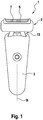
- the hair removal device may be configured as an electric shaver 1 comprising a shaver housing forming a handle 3, wherein in the interior of the handle 3 a drive unit including an electric motor and an electronic control unit may be accommodated.
- Such handle 3 may have an elongated, substantially bone-shaped configuration extending along a longitudinal axis 31.
- a working head 2 may be mounted to said handle 3, wherein the working head 2 may be movably supported at said handle 3.
- the support structure 13 supporting the working head 2 at the handle 3 may allow for one-axial or multi-axial pivot and/or swiveling movements of the entire working head 2 relative to the handle 3.
- the working head 3 may allow for a sort of internal movements. More particularly, the working head 2 includes a pair of short hair cutters 4 and 5 and a pair of trimmers 6 and 7 which are supported movably relative to a working head base structure 14 which may be supported by the aforementioned support structure 13 onto the handle 3.
- the working head 3 may include a pair of support frames 11 and 12 which may be pivotably supported at said base structure 14 about a pivot axis 8 to allow for pivoting movements of the support frames 11 and 12 relative to the base structure 14.
- Said pivot axis 8 may extend parallel to a first plane 9 separating one of the trimmers 6, 7 from one of the short hair cutters 4 and 5 and parallel to a second plane 10 extending substantially perpendicular to the aforementioned longitudinal axis 31 of handle 3.
- the aforementioned short hair cutters 4 and 5 and the aforementioned trimmers 6 and 7 may have an elongated, substantially block-like shape and/or an elongated, substantially rectangular shape, wherein the short hair cutters 4 and 5 may include a flexible mesh screen with a curved surface under which an undercutter and/or cutter blade block may reciprocate.
- the trimmers 6 and 7 may include a pair of sickle finger bars reciprocating relative to each other and/or an apertured foil with relatively large apertures under which an undercutter with cutting blades may reciprocate.
- the skin contact surface of the working head 2 formed by the top surfaces of the aforementioned short hair cutters 4 and 5 and trimmers 6 and 7 may have a strip-like configuration and as a whole, may have a rectangular configuration when viewed from the top.
- the aforementioned pivot axis 8 of the support frames 11 and 12 may be arranged at a height very close to the top surface of the trimmers 6 and 7 and short hair cutters 4 and 5, at least when the support frames 11 and 12 are in an intermediate pivot position in which the trimmers 6 and 7 and short hair cutters 4 and 5 together define a substantially flat plane, cf. Fig. 5 and Fig. 6 .
- the support frames 11 and 12 also may extend substantially in a common plane what is, however, not necessary.
- the support frames 11 and 12 may pivot relative to each other so that the skin contact surface of the working head 2 as defined by the top surfaces of the trimmers 6 and 7 and short hair cutters 4 and 5 may be changed from a substantially concave shape to a substantially convex shape (with a flat configuration in an intermediate position therebetween).
- each of the support frames 11 and 12 may pivot about an angle of at least +/-5° or +/-7° or +/-10° or +/-20° or +/-30° and more.
- each support frame 11 and 12 may pivot about an angle of +/-20°
- said pairs of support frames 11 and 12 may pivot relative to each other over an angular range of about 80°.
- such enveloping planes may define an angle of about 140° to 170° in the first pivot position defining the concave skin contact contour and, on the other hand, an angle of about 190° to 200° in the second pivot position defining the convex skin contact contour, cf. Figures 3 and 4 .
- a biasing device 15 may be provided for biasing the support frames 11 and 12 towards the concave configuration, wherein such biasing device 15 may include a spring device pivoting the support frames 11 and 12 about pivot axis 8 relative to each other only and/or a spring device urging the support frames 11 and 12 away from the base structure 14 of working head 2 and thus away from the handle 3.
- At least one of the trimmers 6 and 7 and/or the short hair cutters 4 and 5 may be movably supported onto said support frames 11 and 12 so as to allow for a diving movement 16 of the respective trimmer 6 or 7 and/or the respective short hair cutter 4 and 5 relative to the support frame 11 and 12.
- Such diving movement 16 may be oriented in a direction substantially perpendicular to the skin contact contour of the working head 2, and/or on a circular path.
- the trimmers 6 and 7 and short hair cutters 4 and 5 may be arranged in an asymmetric manner and/or in an order "short hair cutter - trimmer - short hair cutter - trimmer". More particularly, a short hair cutter 4 may be arranged at an outer side of the working head 2 and a trimmer 7 may be positioned at an opposite outer side of the working head 2, wherein such outer side means the working head portion further away from the center and/or forming a periphery or periphery portion.
- another short hair cutter 5 may be positioned at an inner side and also another trimmer 6 may be positioned at an inner side of the working head 2.
- both short hair cutters 4 and 5 may be positioned at one side of the working head 2 and/or mounted to the same support frame 11, whereas on the other hand both trimmers 6 and 7 may be positioned at the opposite side of the working head 2 and/or mounted to the other support frame 12.
- the order "short hair cutter - short hair cutter - trimmer - trimmer" is achieved.
- the trimmers 6 and 7 may be arranged at opposite outer sides of the working head 2 with the two short hair cutters 4 and 5 positioned therebetween in a middle or center portion of the working head 2.
Claims (18)
- Dispositif d'épilation, en particulier rasoir électrique (1), comprenant une tête fonctionnelle (2) fixée à une poignée (3) pour déplacer la tête fonctionnelle (2) le long d'une surface de la peau, ladite tête fonctionnelle (2) incluant au moins deux dispositifs de coupe pour poils courts (4, 5) et au moins une tondeuse (6, 7) voisine d'au moins l'un desdits dispositifs de coupe pour poils courts (4, 5), dans lequel lesdits dispositifs de coupe pour poils courts (4, 5) et ladite au moins une tondeuse (6, 7) sont mobiles par rapport à ladite poignée (3) sous une pression de contact avec la peau, dans lequel ladite au moins une tondeuse (6, 7) est supportée de manière pivotante autour d'un axe de pivotement (8) pour pivoter par rapport à au moins l'un desdits dispositifs de coupe pour poils courts (4, 5) sous une pression de contact avec la peau, ledit axe de pivotement (8) s'étendant essentiellement parallèle à un premier plan (9) séparant la tondeuse (6, 7) de l'un des dispositifs de coupe pour poils courts (4, 5) et essentiellement parallèle à un deuxième plan (10) perpendiculaire à un axe longitudinal de poignée (31) caractérisé en ce que la tête fonctionnelle inclut au moins deux tondeuses (6, 7).
- Dispositif d'épilation selon la revendication précédente, dans lequel lesdites au moins deux tondeuses (6, 7) et lesdits au moins deux dispositifs de coupe pour poils courts (4, 5) sont montés sur une paire de cadres de support (11, 12) qui sont supportés de manière pivotante l'un par rapport à l'autre autour d'un axe de pivotement commun ou d'axes de pivotement indépendants chacun parallèle auxdits premier et deuxième plans (9, 10) entre une première position de pivotement à laquelle lesdites au moins deux tondeuses (6, 7) et lesdits au moins deux dispositifs de coupe pour poils courts (4, 5) définissent ensemble un contour concave de contact avec la peau (17) de la tête fonctionnelle (2) et une deuxième position de pivotement à laquelle lesdites au moins deux tondeuses (6, 7) et lesdits au moins deux dispositifs de coupe pour poils courts (4, 5) définissent ensemble un contour convexe de contact avec la peau (17) de la tête fonctionnelle (2).
- Dispositif d'épilation selon la revendication précédente, dans lequel ledit axe de pivotement commun (8) ou lesdits axes de pivotement indépendants est/sont agencés dans une partie centrale de la tête fonctionnelle (2).
- Dispositif d'épilation selon l'une quelconque des revendications 2 à 3, dans lequel lesdites au moins deux tondeuses (6, 7) et lesdits au moins deux dispositifs de coupe pour poils courts (4, 5) sont agencés sur des côtés opposés dudit axe de pivotement commun (8) ou sépare des axes de pivotement.
- Dispositif d'épilation selon la revendication 4, dans lequel lesdits axes de pivotement indépendants sont agencés au niveau de parties de bord externes desdits cadres de support (11, 12) ou au niveau de parties médianes desdits cadres de support (11, 12).
- Dispositif d'épilation selon l'une quelconque des revendications 2 à 5, dans lequel ledit axe de pivotement (8) ou axes de pivotement sont agencés essentiellement à la même hauteur que le contour de contact avec la peau (17) de la tête fonctionnelle (2) tel que défini par les surfaces supérieures des tondeuses (6, 7) et des dispositifs de coupe pour poils courts (4, 5) lorsque l'on considère une configuration intermédiaire, plate de ceux-ci.
- Dispositif d'épilation selon la revendication précédente, dans lequel chacune desdites au moins deux tondeuses (6, 7) est supportée de manière pivotante autour d'un axe de pivotement (8) parallèle auxdits premier et deuxième plans (9, 10) par rapport à au moins l'un desdits dispositifs de coupe pour poils courts (4, 5).
- Dispositif d'épilation selon l'une quelconque des revendications 3 à 7, dans lequel chacun desdits cadres de support (11, 12) supporte au moins une tondeuse (6, 7) et au moins l'un desdits dispositifs de coupe pour poils courts (4, 5).
- Dispositif d'épilation selon la revendication précédente, dans lequel l'une desdites tondeuses (6) est positionnée au niveau d'un côté externe de la tête fonctionnelle (2) et voisine de seulement un dispositif de coupe pour poils courts, et une autre desdites tondeuses (7) est positionnée au niveau d'un côté interne de ladite tête fonctionnelle (2) et voisine de deux dispositifs de coupe pour poils courts (4, 5).
- Dispositif d'épilation selon la revendication 8, dans lequel au moins deux dispositifs de coupe pour poils courts (4, 5) sont positionnés au niveau d'un côté interne de ladite tête fonctionnelle (2) entre lesdites au moins deux tondeuses (6, 7).
- Dispositif d'épilation selon la revendication 2, dans lequel un premier desdits cadres de support (11) supporte au moins deux tondeuses (6, 7) et une deuxième de ladite paire de cadres de support (12) supporte lesdits au moins deux dispositifs de coupe pour poils courts (4, 5).
- Dispositif d'épilation selon l'une quelconque des revendications 2 à 11, dans lequel lesdits cadres de support (11, 12) sont sollicités vers la première position de pivotement susmentionnée à laquelle les tondeuses et les dispositifs de coupe pour poils courts définissent ensemble un contour concave de contact avec la peau de la tête fonctionnelle au moyen d'un dispositif de sollicitation (15) pour permettre aux cadres de support (11, 12) de pivoter contre une force de sollicitation et/ou un couple de sollicitation dans la deuxième position de pivotement susmentionnée définissant un contour convexe de contact avec la peau ou une position intermédiaire définissant une configuration plate, lorsque la tête fonctionnelle est pressée contre la surface de la peau.
- Dispositif d'épilation selon la revendication précédente, dans lequel le dispositif de sollicitation (15) inclut un premier élément de sollicitation pour solliciter les cadres de support (11, 12) l'un par rapport à l'autre seulement et/ou un deuxième élément de sollicitation pour solliciter au moins l'un des cadres de support (11, 12) par rapport à la poignée et/ou à une structure de base de tête fonctionnelle (14) pour non seulement contrôler le pivotement des cadres de support (11, 12) les uns par rapport aux autres, mais pour également contrôler le pivotement des cadres de support (11, 12) par rapport à la poignée (3) et/ou par rapport à la structure de base (14) de la tête fonctionnelle (2).
- Dispositif d'épilation selon l'une quelconque des revendications 2 à 13, dans lequel au moins l'un(e) des dispositifs de coupe pour poils courts (4, 5) et/ou tondeuses (6, 7) sont supporté(e)s de manière mobile par rapport aux cadres de support (11, 12) pour permettre la plongée de ladite/dudit au moins un(e) tondeuse et/ou dispositif de coupe pour poils courts respectif/respective sous une pression de contact avec la peau par rapport au cadre de support (11, 12) dans une direction essentiellement perpendiculaire à la surface de contact avec la peau (17) de la tête fonctionnelle (2).
- Dispositif d'épilation selon la revendication précédente, dans lequel ledit/ladite au moins un(e) des dispositifs de coupe pour poils courts (4, 5) et/ou tondeuses (6, 7) est sollicité(e) par rapport au cadre de support (11, 12) dans une position faisant saillie vers la surface de la peau au moyen d'un dispositif de sollicitation pour permettre audit/e au moins un(e) des dispositifs de coupe pour poils courts (4, 5) et/ou tondeuses (6, 7) de plonger dans une position plus rétractée sous la pression de contact avec la peau contre une force de sollicitation.
- Dispositif d'épilation selon l'une quelconque des revendications 2 à 15, dans lequel, lorsque l'on considère une position de pivotement intermédiaire, chacun des cadres de support (11, 12) est supporté pivotant autour d'un angle d'au moins +/-5° ou +/-7° ou +/-10° ou +/-20° ou +/-30° et plus, de sorte que lesdites paires de cadres de support (11, 12) sont pivotantes l'une par rapport à l'autre sur une plage angulaire d'environ au moins 20° ou 28° ou 40° ou 80° ou 120° ou plus.
- Dispositif d'épilation selon l'une quelconque des revendications 2 à 16, dans lequel, lorsque l'on considère deux plans d'enveloppe dont l'un touchant les surfaces supérieures du dispositif de coupe pour poils courts (4, 5) et/ou de la tondeuse (6, 7) sur un cadre de support (11) et l'autre touchant les surfaces supérieures de la tondeuse (6, 7) et/ou du dispositif de coupe pour poils courts (4, 5) sur l'autre cadre de support (12), de tels plans d'enveloppe définissent un angle d'environ 160° à 170° dans la première position de pivotement définissant le contour concave de contact avec la peau et, d'autre part, un angle d'environ 190° à 200° dans la deuxième position de pivotement définissant le contour convexe de contact avec la peau.
- Dispositif d'épilation selon l'une quelconque des revendications précédentes, dans lequel au moins l'un des dispositifs de coupe pour poils courts et/ou au moins l'une des tondeuses est configuré(e) pour venir en contact avec la peau avec une pression de contact plus élevée tandis qu'un(e) autre d'au moins l'un(e) des dispositifs de coupe pour poils courts et/ou tondeuses est configuré(e) pour venir en contact avec la peau avec moins de pression du fait d'une sollicitation différente et/ou de bras de levier différents de l'axe de pivotement, réalisant ainsi une coupe à haute pression et à faible pression en même temps.
Priority Applications (4)
| Application Number | Priority Date | Filing Date | Title |
|---|---|---|---|
| EP18164333.9A EP3546146B1 (fr) | 2018-03-27 | 2018-03-27 | Dispositif d'épilation |
| JP2019044484A JP6892472B2 (ja) | 2018-03-27 | 2019-03-12 | 体毛除去装置 |
| CN201910186458.3A CN110303528B (zh) | 2018-03-27 | 2019-03-13 | 毛发移除装置 |
| US16/364,768 US11478943B2 (en) | 2018-03-27 | 2019-03-26 | Hair removal device |
Applications Claiming Priority (1)
| Application Number | Priority Date | Filing Date | Title |
|---|---|---|---|
| EP18164333.9A EP3546146B1 (fr) | 2018-03-27 | 2018-03-27 | Dispositif d'épilation |
Publications (2)
| Publication Number | Publication Date |
|---|---|
| EP3546146A1 EP3546146A1 (fr) | 2019-10-02 |
| EP3546146B1 true EP3546146B1 (fr) | 2021-08-18 |
Family
ID=61827643
Family Applications (1)
| Application Number | Title | Priority Date | Filing Date |
|---|---|---|---|
| EP18164333.9A Active EP3546146B1 (fr) | 2018-03-27 | 2018-03-27 | Dispositif d'épilation |
Country Status (4)
| Country | Link |
|---|---|
| US (1) | US11478943B2 (fr) |
| EP (1) | EP3546146B1 (fr) |
| JP (1) | JP6892472B2 (fr) |
| CN (1) | CN110303528B (fr) |
Families Citing this family (7)
| Publication number | Priority date | Publication date | Assignee | Title |
|---|---|---|---|---|
| USD868377S1 (en) | 2016-09-28 | 2019-11-26 | Braun Gmbh | Electric dry shaver brush |
| JP1584672S (fr) | 2016-11-10 | 2020-08-24 | ||
| EP3546146B1 (fr) | 2018-03-27 | 2021-08-18 | Braun GmbH | Dispositif d'épilation |
| USD922682S1 (en) * | 2018-08-10 | 2021-06-15 | Braun Gmbh | Electric dry shaver |
| USD950850S1 (en) * | 2020-07-14 | 2022-05-03 | Ce Li | Shaver |
| JP2022155399A (ja) * | 2021-03-30 | 2022-10-13 | パナソニックIpマネジメント株式会社 | 刃ユニット、および電気かみそり |
| JP2023144697A (ja) * | 2022-03-28 | 2023-10-11 | パナソニックIpマネジメント株式会社 | 刃ユニットおよび電気かみそり |
Family Cites Families (29)
| Publication number | Priority date | Publication date | Assignee | Title |
|---|---|---|---|---|
| US2526153A (en) * | 1946-11-20 | 1950-10-17 | Herbert E Page | Multihead dry shaver |
| US2574317A (en) * | 1950-02-06 | 1951-11-06 | Jet Electric Shaver Corp | Electrical shaving device |
| US5189792A (en) * | 1990-12-20 | 1993-03-02 | Matsushita Electric Works, Ltd. | Reciprocatory electric shaver |
| US5398412A (en) * | 1992-04-23 | 1995-03-21 | Matsushita Electric Works, Ltd. | Reciprocatory dry shaver |
| US5367771A (en) * | 1992-05-13 | 1994-11-29 | Sanyo Electric Co., Ltd. | Electric shaver with two rows of outer blades |
| DE4244164C2 (de) * | 1992-12-24 | 1995-09-07 | Braun Ag | Trockenrasierapparat mit einem schwenkbar gelagerten Langhaarschneider |
| JP3528201B2 (ja) * | 1993-05-31 | 2004-05-17 | 松下電工株式会社 | 電気かみそり |
| JP3311520B2 (ja) * | 1994-10-31 | 2002-08-05 | 三洋電機株式会社 | 電気かみそりの外刃組部材の取付構造 |
| JP3716353B2 (ja) * | 1995-07-31 | 2005-11-16 | 九州日立マクセル株式会社 | ロータリ式電気かみそり |
| CN1101297C (zh) * | 1996-05-29 | 2003-02-12 | 三洋电机株式会社 | 电动剃须刀 |
| JP2000509628A (ja) * | 1997-02-17 | 2000-08-02 | コーニンクレッカ フィリップス エレクトロニクス エヌ ヴィ | 髭そり装置 |
| US6317982B1 (en) * | 1999-10-22 | 2001-11-20 | Remington Corporation L.L.C. | Shaving system and adjustable trimmers therefor |
| JP4396094B2 (ja) * | 2002-05-30 | 2010-01-13 | パナソニック電工株式会社 | 電気かみそり |
| US7137205B2 (en) * | 2002-10-01 | 2006-11-21 | The Gillette Company | Linkage mechanism providing a virtual pivot axis for razor apparatus with pivotal head |
| JP2005040358A (ja) | 2003-07-22 | 2005-02-17 | Matsushita Electric Works Ltd | シェーバー |
| JP4747904B2 (ja) * | 2005-07-29 | 2011-08-17 | パナソニック電工株式会社 | シェーバー |
| DE102006010323A1 (de) * | 2006-03-07 | 2007-09-13 | Braun Gmbh | Trockenrasierer mit schwenkbarem Scherkopf |
| DE102006030947A1 (de) * | 2006-07-05 | 2008-01-10 | Braun Gmbh | Elektrischer Trockenrasierapparat |
| JP4207080B2 (ja) * | 2006-12-08 | 2009-01-14 | パナソニック電工株式会社 | 電気かみそり |
| JP5009940B2 (ja) * | 2009-01-15 | 2012-08-29 | パナソニック株式会社 | 電気ひげそり器 |
| JP4988777B2 (ja) * | 2009-01-15 | 2012-08-01 | パナソニック株式会社 | 電気かみそり |
| US9216513B2 (en) * | 2009-03-09 | 2015-12-22 | Koninklijke Philips N.V. | Shaving device with improved contour following |
| WO2011037126A1 (fr) * | 2009-09-25 | 2011-03-31 | パナソニック電工 株式会社 | Rasoir électrique |
| EP2404716B1 (fr) * | 2010-07-10 | 2012-09-26 | Braun GmbH | Appareil électrique de coupe de cheveux |
| EP2425938B1 (fr) * | 2010-09-03 | 2014-02-26 | Braun GmbH | Tête de rasage avec plusieurs unités de rasage |
| WO2016019326A1 (fr) * | 2014-07-31 | 2016-02-04 | Spectrum Brands, Inc. | Rasoir électrique |
| JP6440117B2 (ja) * | 2015-03-06 | 2018-12-19 | パナソニックIpマネジメント株式会社 | 電気かみそりおよびそのヘッド |
| EP3300863B1 (fr) | 2016-09-28 | 2020-06-17 | Braun GmbH | Rasoir électrique |
| EP3546146B1 (fr) | 2018-03-27 | 2021-08-18 | Braun GmbH | Dispositif d'épilation |
-
2018
- 2018-03-27 EP EP18164333.9A patent/EP3546146B1/fr active Active
-
2019
- 2019-03-12 JP JP2019044484A patent/JP6892472B2/ja active Active
- 2019-03-13 CN CN201910186458.3A patent/CN110303528B/zh active Active
- 2019-03-26 US US16/364,768 patent/US11478943B2/en active Active
Non-Patent Citations (1)
| Title |
|---|
| None * |
Also Published As
| Publication number | Publication date |
|---|---|
| CN110303528B (zh) | 2021-09-21 |
| JP6892472B2 (ja) | 2021-06-23 |
| EP3546146A1 (fr) | 2019-10-02 |
| CN110303528A (zh) | 2019-10-08 |
| US11478943B2 (en) | 2022-10-25 |
| US20190299433A1 (en) | 2019-10-03 |
| JP2019171034A (ja) | 2019-10-10 |
Similar Documents
| Publication | Publication Date | Title |
|---|---|---|
| EP3546146B1 (fr) | Dispositif d'épilation | |
| EP3585574B1 (fr) | Tondeuse à cheveux portative électrique avec protection de lame | |
| CN107107351B (zh) | 干式剃刀 | |
| RU2700884C2 (ru) | Режущая головка и устройство для стрижки волос | |
| EP1184141B1 (fr) | Têtes de rasoir avec des élements de protection intermédiaires | |
| CN113618788B (zh) | 电动胡须修剪器 | |
| CN115515767A (zh) | 电动胡须修剪器 | |
| WO2011037126A1 (fr) | Rasoir électrique | |
| EP3300860B1 (fr) | Tondeuse a barbe | |
| WO2018060896A1 (fr) | Tondeuse à barbe | |
| RU2758429C1 (ru) | Машинка для стрижки волос, содержащая гребень | |
| US20140259689A1 (en) | Concaved cutter head assembly for hair trimmer | |
| WO2018060898A1 (fr) | Tondeuse à barbe | |
| CA2383447A1 (fr) | Cartouche de rasage humide a quatre lames | |
| WO2018060894A1 (fr) | Tondeuse à barbe | |
| JPH0446156B2 (fr) | ||
| US10792824B2 (en) | Beard trimmer | |
| US20040055156A1 (en) | Safety razor | |
| JPH0220268B2 (fr) | ||
| EP2926959B1 (fr) | Tondeuse à cheveux, unité de tête de celle-ci et lame mobile associée | |
| EP2892696B1 (fr) | Dispositif de coupe de cheveux | |
| WO2023043629A1 (fr) | Ensemble de lame de tondeuse à cheveux à géométrie de dents en réseau à angle de coupe variable |
Legal Events
| Date | Code | Title | Description |
|---|---|---|---|
| PUAI | Public reference made under article 153(3) epc to a published international application that has entered the european phase |
Free format text: ORIGINAL CODE: 0009012 |
|
| STAA | Information on the status of an ep patent application or granted ep patent |
Free format text: STATUS: THE APPLICATION HAS BEEN PUBLISHED |
|
| AK | Designated contracting states |
Kind code of ref document: A1 Designated state(s): AL AT BE BG CH CY CZ DE DK EE ES FI FR GB GR HR HU IE IS IT LI LT LU LV MC MK MT NL NO PL PT RO RS SE SI SK SM TR |
|
| AX | Request for extension of the european patent |
Extension state: BA ME |
|
| STAA | Information on the status of an ep patent application or granted ep patent |
Free format text: STATUS: REQUEST FOR EXAMINATION WAS MADE |
|
| 17P | Request for examination filed |
Effective date: 20200416 |
|
| RBV | Designated contracting states (corrected) |
Designated state(s): AL AT BE BG CH CY CZ DE DK EE ES FI FR GB GR HR HU IE IS IT LI LT LU LV MC MK MT NL NO PL PT RO RS SE SI SK SM TR |
|
| STAA | Information on the status of an ep patent application or granted ep patent |
Free format text: STATUS: EXAMINATION IS IN PROGRESS |
|
| 17Q | First examination report despatched |
Effective date: 20200715 |
|
| STAA | Information on the status of an ep patent application or granted ep patent |
Free format text: STATUS: EXAMINATION IS IN PROGRESS |
|
| GRAP | Despatch of communication of intention to grant a patent |
Free format text: ORIGINAL CODE: EPIDOSNIGR1 |
|
| STAA | Information on the status of an ep patent application or granted ep patent |
Free format text: STATUS: GRANT OF PATENT IS INTENDED |
|
| INTG | Intention to grant announced |
Effective date: 20210317 |
|
| GRAS | Grant fee paid |
Free format text: ORIGINAL CODE: EPIDOSNIGR3 |
|
| GRAA | (expected) grant |
Free format text: ORIGINAL CODE: 0009210 |
|
| STAA | Information on the status of an ep patent application or granted ep patent |
Free format text: STATUS: THE PATENT HAS BEEN GRANTED |
|
| AK | Designated contracting states |
Kind code of ref document: B1 Designated state(s): AL AT BE BG CH CY CZ DE DK EE ES FI FR GB GR HR HU IE IS IT LI LT LU LV MC MK MT NL NO PL PT RO RS SE SI SK SM TR |
|
| REG | Reference to a national code |
Ref country code: GB Ref legal event code: FG4D |
|
| REG | Reference to a national code |
Ref country code: CH Ref legal event code: EP |
|
| REG | Reference to a national code |
Ref country code: DE Ref legal event code: R096 Ref document number: 602018021886 Country of ref document: DE |
|
| REG | Reference to a national code |
Ref country code: IE Ref legal event code: FG4D Ref country code: AT Ref legal event code: REF Ref document number: 1421208 Country of ref document: AT Kind code of ref document: T Effective date: 20210915 |
|
| REG | Reference to a national code |
Ref country code: LT Ref legal event code: MG9D |
|
| REG | Reference to a national code |
Ref country code: NL Ref legal event code: FP |
|
| REG | Reference to a national code |
Ref country code: AT Ref legal event code: MK05 Ref document number: 1421208 Country of ref document: AT Kind code of ref document: T Effective date: 20210818 |
|
| PG25 | Lapsed in a contracting state [announced via postgrant information from national office to epo] |
Ref country code: HR Free format text: LAPSE BECAUSE OF FAILURE TO SUBMIT A TRANSLATION OF THE DESCRIPTION OR TO PAY THE FEE WITHIN THE PRESCRIBED TIME-LIMIT Effective date: 20210818 Ref country code: FI Free format text: LAPSE BECAUSE OF FAILURE TO SUBMIT A TRANSLATION OF THE DESCRIPTION OR TO PAY THE FEE WITHIN THE PRESCRIBED TIME-LIMIT Effective date: 20210818 Ref country code: ES Free format text: LAPSE BECAUSE OF FAILURE TO SUBMIT A TRANSLATION OF THE DESCRIPTION OR TO PAY THE FEE WITHIN THE PRESCRIBED TIME-LIMIT Effective date: 20210818 Ref country code: RS Free format text: LAPSE BECAUSE OF FAILURE TO SUBMIT A TRANSLATION OF THE DESCRIPTION OR TO PAY THE FEE WITHIN THE PRESCRIBED TIME-LIMIT Effective date: 20210818 Ref country code: SE Free format text: LAPSE BECAUSE OF FAILURE TO SUBMIT A TRANSLATION OF THE DESCRIPTION OR TO PAY THE FEE WITHIN THE PRESCRIBED TIME-LIMIT Effective date: 20210818 Ref country code: LT Free format text: LAPSE BECAUSE OF FAILURE TO SUBMIT A TRANSLATION OF THE DESCRIPTION OR TO PAY THE FEE WITHIN THE PRESCRIBED TIME-LIMIT Effective date: 20210818 Ref country code: BG Free format text: LAPSE BECAUSE OF FAILURE TO SUBMIT A TRANSLATION OF THE DESCRIPTION OR TO PAY THE FEE WITHIN THE PRESCRIBED TIME-LIMIT Effective date: 20211118 Ref country code: AT Free format text: LAPSE BECAUSE OF FAILURE TO SUBMIT A TRANSLATION OF THE DESCRIPTION OR TO PAY THE FEE WITHIN THE PRESCRIBED TIME-LIMIT Effective date: 20210818 Ref country code: NO Free format text: LAPSE BECAUSE OF FAILURE TO SUBMIT A TRANSLATION OF THE DESCRIPTION OR TO PAY THE FEE WITHIN THE PRESCRIBED TIME-LIMIT Effective date: 20211118 Ref country code: PT Free format text: LAPSE BECAUSE OF FAILURE TO SUBMIT A TRANSLATION OF THE DESCRIPTION OR TO PAY THE FEE WITHIN THE PRESCRIBED TIME-LIMIT Effective date: 20211220 |
|
| PG25 | Lapsed in a contracting state [announced via postgrant information from national office to epo] |
Ref country code: PL Free format text: LAPSE BECAUSE OF FAILURE TO SUBMIT A TRANSLATION OF THE DESCRIPTION OR TO PAY THE FEE WITHIN THE PRESCRIBED TIME-LIMIT Effective date: 20210818 Ref country code: LV Free format text: LAPSE BECAUSE OF FAILURE TO SUBMIT A TRANSLATION OF THE DESCRIPTION OR TO PAY THE FEE WITHIN THE PRESCRIBED TIME-LIMIT Effective date: 20210818 Ref country code: GR Free format text: LAPSE BECAUSE OF FAILURE TO SUBMIT A TRANSLATION OF THE DESCRIPTION OR TO PAY THE FEE WITHIN THE PRESCRIBED TIME-LIMIT Effective date: 20211119 |
|
| PG25 | Lapsed in a contracting state [announced via postgrant information from national office to epo] |
Ref country code: DK Free format text: LAPSE BECAUSE OF FAILURE TO SUBMIT A TRANSLATION OF THE DESCRIPTION OR TO PAY THE FEE WITHIN THE PRESCRIBED TIME-LIMIT Effective date: 20210818 |
|
| REG | Reference to a national code |
Ref country code: DE Ref legal event code: R097 Ref document number: 602018021886 Country of ref document: DE |
|
| PG25 | Lapsed in a contracting state [announced via postgrant information from national office to epo] |
Ref country code: SM Free format text: LAPSE BECAUSE OF FAILURE TO SUBMIT A TRANSLATION OF THE DESCRIPTION OR TO PAY THE FEE WITHIN THE PRESCRIBED TIME-LIMIT Effective date: 20210818 Ref country code: SK Free format text: LAPSE BECAUSE OF FAILURE TO SUBMIT A TRANSLATION OF THE DESCRIPTION OR TO PAY THE FEE WITHIN THE PRESCRIBED TIME-LIMIT Effective date: 20210818 Ref country code: RO Free format text: LAPSE BECAUSE OF FAILURE TO SUBMIT A TRANSLATION OF THE DESCRIPTION OR TO PAY THE FEE WITHIN THE PRESCRIBED TIME-LIMIT Effective date: 20210818 Ref country code: EE Free format text: LAPSE BECAUSE OF FAILURE TO SUBMIT A TRANSLATION OF THE DESCRIPTION OR TO PAY THE FEE WITHIN THE PRESCRIBED TIME-LIMIT Effective date: 20210818 Ref country code: CZ Free format text: LAPSE BECAUSE OF FAILURE TO SUBMIT A TRANSLATION OF THE DESCRIPTION OR TO PAY THE FEE WITHIN THE PRESCRIBED TIME-LIMIT Effective date: 20210818 Ref country code: AL Free format text: LAPSE BECAUSE OF FAILURE TO SUBMIT A TRANSLATION OF THE DESCRIPTION OR TO PAY THE FEE WITHIN THE PRESCRIBED TIME-LIMIT Effective date: 20210818 |
|
| PLBE | No opposition filed within time limit |
Free format text: ORIGINAL CODE: 0009261 |
|
| STAA | Information on the status of an ep patent application or granted ep patent |
Free format text: STATUS: NO OPPOSITION FILED WITHIN TIME LIMIT |
|
| 26N | No opposition filed |
Effective date: 20220519 |
|
| PG25 | Lapsed in a contracting state [announced via postgrant information from national office to epo] |
Ref country code: IT Free format text: LAPSE BECAUSE OF FAILURE TO SUBMIT A TRANSLATION OF THE DESCRIPTION OR TO PAY THE FEE WITHIN THE PRESCRIBED TIME-LIMIT Effective date: 20210818 |
|
| PG25 | Lapsed in a contracting state [announced via postgrant information from national office to epo] |
Ref country code: SI Free format text: LAPSE BECAUSE OF FAILURE TO SUBMIT A TRANSLATION OF THE DESCRIPTION OR TO PAY THE FEE WITHIN THE PRESCRIBED TIME-LIMIT Effective date: 20210818 |
|
| PG25 | Lapsed in a contracting state [announced via postgrant information from national office to epo] |
Ref country code: MC Free format text: LAPSE BECAUSE OF FAILURE TO SUBMIT A TRANSLATION OF THE DESCRIPTION OR TO PAY THE FEE WITHIN THE PRESCRIBED TIME-LIMIT Effective date: 20210818 |
|
| REG | Reference to a national code |
Ref country code: CH Ref legal event code: PL |
|
| REG | Reference to a national code |
Ref country code: BE Ref legal event code: MM Effective date: 20220331 |
|
| PG25 | Lapsed in a contracting state [announced via postgrant information from national office to epo] |
Ref country code: LU Free format text: LAPSE BECAUSE OF NON-PAYMENT OF DUE FEES Effective date: 20220327 Ref country code: LI Free format text: LAPSE BECAUSE OF NON-PAYMENT OF DUE FEES Effective date: 20220331 Ref country code: IE Free format text: LAPSE BECAUSE OF NON-PAYMENT OF DUE FEES Effective date: 20220327 Ref country code: CH Free format text: LAPSE BECAUSE OF NON-PAYMENT OF DUE FEES Effective date: 20220331 |
|
| PG25 | Lapsed in a contracting state [announced via postgrant information from national office to epo] |
Ref country code: BE Free format text: LAPSE BECAUSE OF NON-PAYMENT OF DUE FEES Effective date: 20220331 |
|
| PGFP | Annual fee paid to national office [announced via postgrant information from national office to epo] |
Ref country code: NL Payment date: 20230215 Year of fee payment: 6 |
|
| PGFP | Annual fee paid to national office [announced via postgrant information from national office to epo] |
Ref country code: FR Payment date: 20230208 Year of fee payment: 6 |
|
| PGFP | Annual fee paid to national office [announced via postgrant information from national office to epo] |
Ref country code: GB Payment date: 20230202 Year of fee payment: 6 Ref country code: DE Payment date: 20230131 Year of fee payment: 6 |
|
| PGFP | Annual fee paid to national office [announced via postgrant information from national office to epo] |
Ref country code: NL Payment date: 20240214 Year of fee payment: 7 |