EP3545360B1 - Belichtungsvorrichtung und verfahren zur belichtung von plattenförmigen materialien - Google Patents
Belichtungsvorrichtung und verfahren zur belichtung von plattenförmigen materialien Download PDFInfo
- Publication number
- EP3545360B1 EP3545360B1 EP17811248.8A EP17811248A EP3545360B1 EP 3545360 B1 EP3545360 B1 EP 3545360B1 EP 17811248 A EP17811248 A EP 17811248A EP 3545360 B1 EP3545360 B1 EP 3545360B1
- Authority
- EP
- European Patent Office
- Prior art keywords
- exposure
- exposure unit
- unit
- plate
- shaped material
- Prior art date
- Legal status (The legal status is an assumption and is not a legal conclusion. Google has not performed a legal analysis and makes no representation as to the accuracy of the status listed.)
- Active
Links
- 239000000463 material Substances 0.000 title claims description 228
- 238000000034 method Methods 0.000 title claims description 38
- 238000003384 imaging method Methods 0.000 title claims description 24
- 238000007639 printing Methods 0.000 claims description 56
- 230000005670 electromagnetic radiation Effects 0.000 claims description 9
- 238000005406 washing Methods 0.000 claims description 6
- 238000001035 drying Methods 0.000 claims description 5
- 239000010410 layer Substances 0.000 description 62
- 230000032258 transport Effects 0.000 description 53
- 230000005855 radiation Effects 0.000 description 17
- 230000008569 process Effects 0.000 description 13
- 238000004519 manufacturing process Methods 0.000 description 9
- 239000011230 binding agent Substances 0.000 description 8
- 230000004888 barrier function Effects 0.000 description 6
- XLYOFNOQVPJJNP-UHFFFAOYSA-N water Substances O XLYOFNOQVPJJNP-UHFFFAOYSA-N 0.000 description 6
- 239000004952 Polyamide Substances 0.000 description 5
- 239000007864 aqueous solution Substances 0.000 description 5
- 239000011261 inert gas Substances 0.000 description 5
- 229920002647 polyamide Polymers 0.000 description 5
- 239000002904 solvent Substances 0.000 description 5
- 238000001228 spectrum Methods 0.000 description 5
- QVGXLLKOCUKJST-UHFFFAOYSA-N atomic oxygen Chemical compound [O] QVGXLLKOCUKJST-UHFFFAOYSA-N 0.000 description 4
- 238000011161 development Methods 0.000 description 4
- 239000001301 oxygen Substances 0.000 description 4
- 229910052760 oxygen Inorganic materials 0.000 description 4
- 238000012546 transfer Methods 0.000 description 4
- 239000006229 carbon black Substances 0.000 description 3
- 230000009975 flexible effect Effects 0.000 description 3
- 239000011521 glass Substances 0.000 description 3
- 239000000203 mixture Substances 0.000 description 3
- 238000012545 processing Methods 0.000 description 3
- 239000000758 substrate Substances 0.000 description 3
- XKRFYHLGVUSROY-UHFFFAOYSA-N Argon Chemical compound [Ar] XKRFYHLGVUSROY-UHFFFAOYSA-N 0.000 description 2
- IJGRMHOSHXDMSA-UHFFFAOYSA-N Atomic nitrogen Chemical compound N#N IJGRMHOSHXDMSA-UHFFFAOYSA-N 0.000 description 2
- CURLTUGMZLYLDI-UHFFFAOYSA-N Carbon dioxide Chemical compound O=C=O CURLTUGMZLYLDI-UHFFFAOYSA-N 0.000 description 2
- 230000002745 absorbent Effects 0.000 description 2
- 239000002250 absorbent Substances 0.000 description 2
- 239000006096 absorbing agent Substances 0.000 description 2
- 230000015572 biosynthetic process Effects 0.000 description 2
- 239000003795 chemical substances by application Substances 0.000 description 2
- 239000010408 film Substances 0.000 description 2
- 238000007641 inkjet printing Methods 0.000 description 2
- 239000000178 monomer Substances 0.000 description 2
- 229920003023 plastic Polymers 0.000 description 2
- 239000004033 plastic Substances 0.000 description 2
- 229920001200 poly(ethylene-vinyl acetate) Polymers 0.000 description 2
- -1 polyethylene Polymers 0.000 description 2
- 229920000642 polymer Polymers 0.000 description 2
- 229920002689 polyvinyl acetate Polymers 0.000 description 2
- 239000011118 polyvinyl acetate Substances 0.000 description 2
- 229920002451 polyvinyl alcohol Polymers 0.000 description 2
- 235000019422 polyvinyl alcohol Nutrition 0.000 description 2
- 238000004080 punching Methods 0.000 description 2
- 239000007787 solid Substances 0.000 description 2
- 238000003860 storage Methods 0.000 description 2
- 229920002799 BoPET Polymers 0.000 description 1
- ZTQSAGDEMFDKMZ-UHFFFAOYSA-N Butyraldehyde Chemical compound CCCC=O ZTQSAGDEMFDKMZ-UHFFFAOYSA-N 0.000 description 1
- 239000000020 Nitrocellulose Substances 0.000 description 1
- 239000004698 Polyethylene Substances 0.000 description 1
- 239000004743 Polypropylene Substances 0.000 description 1
- 239000004372 Polyvinyl alcohol Substances 0.000 description 1
- 239000002174 Styrene-butadiene Substances 0.000 description 1
- 239000004809 Teflon Substances 0.000 description 1
- 229920006362 Teflon® Polymers 0.000 description 1
- 238000002679 ablation Methods 0.000 description 1
- 239000011358 absorbing material Substances 0.000 description 1
- 230000009471 action Effects 0.000 description 1
- 239000000654 additive Substances 0.000 description 1
- 239000012790 adhesive layer Substances 0.000 description 1
- 229920013820 alkyl cellulose Polymers 0.000 description 1
- 229910052786 argon Inorganic materials 0.000 description 1
- 238000003491 array Methods 0.000 description 1
- 239000012298 atmosphere Substances 0.000 description 1
- 230000001588 bifunctional effect Effects 0.000 description 1
- 229920001400 block copolymer Polymers 0.000 description 1
- MTAZNLWOLGHBHU-UHFFFAOYSA-N butadiene-styrene rubber Chemical compound C=CC=C.C=CC1=CC=CC=C1 MTAZNLWOLGHBHU-UHFFFAOYSA-N 0.000 description 1
- 239000001569 carbon dioxide Substances 0.000 description 1
- 229910002092 carbon dioxide Inorganic materials 0.000 description 1
- 229920002678 cellulose Polymers 0.000 description 1
- 239000001913 cellulose Substances 0.000 description 1
- 235000010980 cellulose Nutrition 0.000 description 1
- 229920006217 cellulose acetate butyrate Polymers 0.000 description 1
- 238000010276 construction Methods 0.000 description 1
- 238000001816 cooling Methods 0.000 description 1
- 239000013039 cover film Substances 0.000 description 1
- 238000004132 cross linking Methods 0.000 description 1
- 125000004122 cyclic group Chemical group 0.000 description 1
- 238000013461 design Methods 0.000 description 1
- 235000014113 dietary fatty acids Nutrition 0.000 description 1
- 238000009792 diffusion process Methods 0.000 description 1
- 239000006185 dispersion Substances 0.000 description 1
- 239000000975 dye Substances 0.000 description 1
- 229920001971 elastomer Polymers 0.000 description 1
- 239000000839 emulsion Substances 0.000 description 1
- 239000000194 fatty acid Substances 0.000 description 1
- 229930195729 fatty acid Natural products 0.000 description 1
- 150000004665 fatty acids Chemical class 0.000 description 1
- 239000007789 gas Substances 0.000 description 1
- 229920013821 hydroxy alkyl cellulose Polymers 0.000 description 1
- 239000007788 liquid Substances 0.000 description 1
- 239000011344 liquid material Substances 0.000 description 1
- 229920001220 nitrocellulos Polymers 0.000 description 1
- 229910052757 nitrogen Inorganic materials 0.000 description 1
- 229910052756 noble gas Inorganic materials 0.000 description 1
- 239000003960 organic solvent Substances 0.000 description 1
- 230000035699 permeability Effects 0.000 description 1
- 239000000049 pigment Substances 0.000 description 1
- 239000004014 plasticizer Substances 0.000 description 1
- 229920000058 polyacrylate Polymers 0.000 description 1
- 229920000515 polycarbonate Polymers 0.000 description 1
- 239000004417 polycarbonate Substances 0.000 description 1
- 150000004291 polyenes Chemical class 0.000 description 1
- 229920000728 polyester Polymers 0.000 description 1
- 229920006149 polyester-amide block copolymer Polymers 0.000 description 1
- 229920000573 polyethylene Polymers 0.000 description 1
- 238000006116 polymerization reaction Methods 0.000 description 1
- 230000000379 polymerizing effect Effects 0.000 description 1
- 229920001155 polypropylene Polymers 0.000 description 1
- 229920000346 polystyrene-polyisoprene block-polystyrene Polymers 0.000 description 1
- 229920002635 polyurethane Polymers 0.000 description 1
- 239000004814 polyurethane Substances 0.000 description 1
- 229920000036 polyvinylpyrrolidone Polymers 0.000 description 1
- 239000001267 polyvinylpyrrolidone Substances 0.000 description 1
- 235000013855 polyvinylpyrrolidone Nutrition 0.000 description 1
- 239000011241 protective layer Substances 0.000 description 1
- 239000010453 quartz Substances 0.000 description 1
- 239000005060 rubber Substances 0.000 description 1
- 150000004760 silicates Chemical class 0.000 description 1
- VYPSYNLAJGMNEJ-UHFFFAOYSA-N silicon dioxide Inorganic materials O=[Si]=O VYPSYNLAJGMNEJ-UHFFFAOYSA-N 0.000 description 1
- 239000011343 solid material Substances 0.000 description 1
- 239000011115 styrene butadiene Substances 0.000 description 1
- 229920003048 styrene butadiene rubber Polymers 0.000 description 1
- 239000000126 substance Substances 0.000 description 1
- 230000008646 thermal stress Effects 0.000 description 1
- 239000012780 transparent material Substances 0.000 description 1
- 238000002604 ultrasonography Methods 0.000 description 1
Images


Classifications
-
- B—PERFORMING OPERATIONS; TRANSPORTING
- B41—PRINTING; LINING MACHINES; TYPEWRITERS; STAMPS
- B41C—PROCESSES FOR THE MANUFACTURE OR REPRODUCTION OF PRINTING SURFACES
- B41C1/00—Forme preparation
- B41C1/02—Engraving; Heads therefor
- B41C1/04—Engraving; Heads therefor using heads controlled by an electric information signal
- B41C1/05—Heat-generating engraving heads, e.g. laser beam, electron beam
-
- G—PHYSICS
- G03—PHOTOGRAPHY; CINEMATOGRAPHY; ANALOGOUS TECHNIQUES USING WAVES OTHER THAN OPTICAL WAVES; ELECTROGRAPHY; HOLOGRAPHY
- G03F—PHOTOMECHANICAL PRODUCTION OF TEXTURED OR PATTERNED SURFACES, e.g. FOR PRINTING, FOR PROCESSING OF SEMICONDUCTOR DEVICES; MATERIALS THEREFOR; ORIGINALS THEREFOR; APPARATUS SPECIALLY ADAPTED THEREFOR
- G03F7/00—Photomechanical, e.g. photolithographic, production of textured or patterned surfaces, e.g. printing surfaces; Materials therefor, e.g. comprising photoresists; Apparatus specially adapted therefor
- G03F7/20—Exposure; Apparatus therefor
- G03F7/2051—Exposure without an original mask, e.g. using a programmed deflection of a point source, by scanning, by drawing with a light beam, using an addressed light or corpuscular source
- G03F7/2053—Exposure without an original mask, e.g. using a programmed deflection of a point source, by scanning, by drawing with a light beam, using an addressed light or corpuscular source using a laser
- G03F7/2055—Exposure without an original mask, e.g. using a programmed deflection of a point source, by scanning, by drawing with a light beam, using an addressed light or corpuscular source using a laser for the production of printing plates; Exposure of liquid photohardening compositions
-
- B—PERFORMING OPERATIONS; TRANSPORTING
- B41—PRINTING; LINING MACHINES; TYPEWRITERS; STAMPS
- B41N—PRINTING PLATES OR FOILS; MATERIALS FOR SURFACES USED IN PRINTING MACHINES FOR PRINTING, INKING, DAMPING, OR THE LIKE; PREPARING SUCH SURFACES FOR USE AND CONSERVING THEM
- B41N1/00—Printing plates or foils; Materials therefor
- B41N1/12—Printing plates or foils; Materials therefor non-metallic other than stone, e.g. printing plates or foils comprising inorganic materials in an organic matrix
-
- G—PHYSICS
- G03—PHOTOGRAPHY; CINEMATOGRAPHY; ANALOGOUS TECHNIQUES USING WAVES OTHER THAN OPTICAL WAVES; ELECTROGRAPHY; HOLOGRAPHY
- G03F—PHOTOMECHANICAL PRODUCTION OF TEXTURED OR PATTERNED SURFACES, e.g. FOR PRINTING, FOR PROCESSING OF SEMICONDUCTOR DEVICES; MATERIALS THEREFOR; ORIGINALS THEREFOR; APPARATUS SPECIALLY ADAPTED THEREFOR
- G03F7/00—Photomechanical, e.g. photolithographic, production of textured or patterned surfaces, e.g. printing surfaces; Materials therefor, e.g. comprising photoresists; Apparatus specially adapted therefor
- G03F7/20—Exposure; Apparatus therefor
- G03F7/2002—Exposure; Apparatus therefor with visible light or UV light, through an original having an opaque pattern on a transparent support, e.g. film printing, projection printing; by reflection of visible or UV light from an original such as a printed image
- G03F7/2004—Exposure; Apparatus therefor with visible light or UV light, through an original having an opaque pattern on a transparent support, e.g. film printing, projection printing; by reflection of visible or UV light from an original such as a printed image characterised by the use of a particular light source, e.g. fluorescent lamps or deep UV light
-
- G—PHYSICS
- G03—PHOTOGRAPHY; CINEMATOGRAPHY; ANALOGOUS TECHNIQUES USING WAVES OTHER THAN OPTICAL WAVES; ELECTROGRAPHY; HOLOGRAPHY
- G03F—PHOTOMECHANICAL PRODUCTION OF TEXTURED OR PATTERNED SURFACES, e.g. FOR PRINTING, FOR PROCESSING OF SEMICONDUCTOR DEVICES; MATERIALS THEREFOR; ORIGINALS THEREFOR; APPARATUS SPECIALLY ADAPTED THEREFOR
- G03F7/00—Photomechanical, e.g. photolithographic, production of textured or patterned surfaces, e.g. printing surfaces; Materials therefor, e.g. comprising photoresists; Apparatus specially adapted therefor
- G03F7/20—Exposure; Apparatus therefor
- G03F7/24—Curved surfaces
-
- G—PHYSICS
- G03—PHOTOGRAPHY; CINEMATOGRAPHY; ANALOGOUS TECHNIQUES USING WAVES OTHER THAN OPTICAL WAVES; ELECTROGRAPHY; HOLOGRAPHY
- G03F—PHOTOMECHANICAL PRODUCTION OF TEXTURED OR PATTERNED SURFACES, e.g. FOR PRINTING, FOR PROCESSING OF SEMICONDUCTOR DEVICES; MATERIALS THEREFOR; ORIGINALS THEREFOR; APPARATUS SPECIALLY ADAPTED THEREFOR
- G03F7/00—Photomechanical, e.g. photolithographic, production of textured or patterned surfaces, e.g. printing surfaces; Materials therefor, e.g. comprising photoresists; Apparatus specially adapted therefor
- G03F7/70—Microphotolithographic exposure; Apparatus therefor
- G03F7/70425—Imaging strategies, e.g. for increasing throughput or resolution, printing product fields larger than the image field or compensating lithography- or non-lithography errors, e.g. proximity correction, mix-and-match, stitching or double patterning
Definitions
- the invention relates to an exposure device for exposing plate-shaped materials, a method for exposing plate-shaped materials and a printing form which was produced from a plate-shaped material according to one of the methods.
- the plate-shaped material is, in particular, printing elements suitable for the production of printing forms.
- pressure elements are known in principle in the prior art. They comprise at least one dimensionally stable carrier and a relief-forming layer.
- the printing forms can have an imageable layer, which can be, for example, a laser-ablatable layer, a layer that can be written on by means of an ink-jet printer, or a thermographic layer, with laser-ablatable layers, also called LAMS (laser-ablatable mask layers), on are the most common.
- LAMS laser-ablatable mask layers
- the use of photopolymerizable layers is customary for the relief-forming layer.
- barrier layers are usually used in order to keep away undesirable substances such as water and / or oxygen.
- a mask is first written into the imageable layer using an IR laser.
- IR laser can be laser devices with rotating drums, flat bed devices or internal drum lasers.
- UV exposure devices are used, which can comprise various UV sources, for example UV tubes or UV LEDs.
- the remains of the mask and the unpolymerized portions of the photopolymerizable layer are removed. This can be done using one or more solvents or thermally. Special washers, e.g. brush washers, are used for washing with solvents and / or water or aqueous solutions.
- Special washers e.g. brush washers, are used for washing with solvents and / or water or aqueous solutions.
- developers can be used in which a development medium (for example an absorbent fleece) is brought into contact with the liquefied, unexposed layer and removed. If solvents are used to develop the plate, this is followed by a drying step in a dryer.
- WO 2016/096945 A1 a method and a corresponding device are known in which, for the production of flexographic printing plates, multiple exposure is carried out with LEDs (light-emitting diodes) using different exposure intensities in several exposure cycles.
- the individual exposure cycles are implemented by moving UV LEDs parallel to the surface of a flexographic printing element.
- the UV LEDs are arranged on one or more LED strips that are moved parallel to the surface of the flexographic printing element.
- the LEDs can be permanently installed and the flexographic printing element can be moved or, conversely, the flexographic printing element can rest during the exposure and the LEDs can be moved.
- at least one of the LED strips can be arranged to be stationary and further LED strips can be arranged to be movable.
- a device for in-line production of flexographic printing plates by means of digital imaging comprises a first exposure unit comprising a plurality of LEDs arranged in an array, which can emit UV light with an intensity of 100 mW / cm 2 , and a second exposure unit comprising one of LEDs different UV radiation source, preferably a UV tube or a UV radiator.
- the exposure takes place in a first exposure step with an intensity of 100 mW / cm 2 and a second exposure step with an intensity of ⁇ 100 mW / cm 2 .
- printing plates are arranged on a rotating drum and exposed to a UV source, for example an LED array, while the drum is rotating.
- a UV source for example an LED array
- the UV source is shifted in a direction parallel to the axis of the drum.
- the length of the UV light source corresponds to the length of the drum and no movement of the UV light source is provided, only the drum rotates.
- an exposure device which comprises a drum, a UV light source and an imaging unit. Furthermore, a method is described in which a mask is written via a laser of the imaging unit and an exposure is carried out via the UV light source, which leads to the formation of surface structures with flat surfaces (Flat Top Dots, FTD). Another mask is then written and an exposure carried out, which leads to the formation of surface structures with round surfaces (round top dots). The process is very time-consuming due to the multiple writing of masks.
- the document WO 2014/035566 A1 describes a flexographic printing plate which is exposed by means of UV-LEDs, the exposure being carried out with two UV-LED arrangements.
- the two UV-LED arrangements preferably have different wavelengths.
- US 6,211,942 B1 a system for double-sided exposure of substrates is known.
- the device comprises a single UV light source, the light from the lamp being directed onto a rotatable mirror. By rotating the mirror, the light from the lamp can be guided in two different directions, with the mirror in a first position guiding UV light through a first mask onto a first side of the substrate and with the mirror in a second position UV light is passed through a second mask onto the second side of the substrate. There is no provision for moving or rotating the UV light source itself.
- An object of the invention can thus be seen in providing a device and a method with which both sides of a plate-shaped material can be exposed without manual turning.
- Exposure devices which each provide an exposure unit for both sides of the plate-shaped material are complex. If both sides are provided with LEDs as a light source for the exposure, this also results in high costs, since UV LEDs with high power are very expensive.
- a further object of the invention can thus be seen in providing an improved exposure device in which the number of exposure units required is reduced.
- the plate-shaped material has a first side and a second side opposite the first side.
- the exposure device comprises a first exposure unit and a Transport unit, wherein the first exposure unit is designed to be rotatable about an axis, wherein the first exposure unit can assume a first position and a second position by rotating around the axis and the first exposure unit and the transport unit are set up such that in a first position of the first exposure unit the first side of the plate-shaped material is fed for an exposure and moved past the first exposure unit and the second side of the plate-shaped material is fed for an exposure and moved past the first exposure unit in a second position of the first exposure unit.
- the plate-shaped material is preferably printing elements and particularly preferably flexographic printing elements which are processed into printing forms or into flexographic printing forms.
- the term “first side” of the plate-shaped material can denote the front side or the rear side of the plate-shaped material, the term “second side” correspondingly denoting the other side of the plate-shaped material.
- photopolymerizable printing elements are preferably used as the plate-shaped material.
- photopolymerizable flexographic printing elements which comprise at least one dimensionally stable carrier, a relief-forming, photopolymerizable layer, which can preferably be washed out in organic washing agents, and an imageable layer.
- Printing elements which comprise a digitally imageable layer are preferred.
- Plate-shaped, digitally imageable flexographic printing elements are known in principle to the person skilled in the art, and they are commercially available. Examples of such flexographic printing elements are for example in U.S. 5,262,275 , EP-A-1,069,475 , WO 2008/095994 A1 , WO 2009/141256 A1 or WO 2012/010459 A1 described. The person skilled in the art makes a suitable selection depending on the desired properties of the flexographic printing plate.
- flexographic printing elements with a carrier film with a thickness of 50 to 300 ⁇ m can preferably be used.
- a carrier film made of a material that is at least partially transparent to UV light, in order to allow the rear side pre-exposure of the flexographic printing element.
- PET films are particularly suitable.
- the photopolymerizable, relief-forming layer comprises, in a manner known in principle, at least one elastomeric binder, an ethylenically unsaturated monomer and a photoinitiator or a photoinitiator system.
- further components such as plasticizers, for example, can optionally be present.
- It is preferably a layer which is soluble in organic washing agents or in water or aqueous solutions or a layer that can be liquefied by increasing the temperature, but flexographic printing elements with water-soluble, relief-forming layers can of course also be processed in the device according to the invention.
- the elastomeric binders can be, for example, thermoplastic-elastomeric block copolymers, for example styrene-butadiene or styrene-isoprene block copolymers.
- the relief-forming layer generally has a layer thickness of 300 ⁇ m to 7000 ⁇ m, preferably 1000 ⁇ m to 5000 ⁇ m.
- the flexographic printing element used can also comprise several photopolymerizable, relief-forming layers of different composition on top of one another.
- the digitally imageable layer can be, for example, a laser-ablatable layer, a layer that can be written on by means of an ink-jet printer, or a thermographic layer. It is preferably a laser-ablatable layer.
- the laser-ablatable mask layer also called LAMS layer, comprises at least one elastic binding agent, in particular a flexible elastic binding agent.
- binders include flexible polyamides.
- Such polyamides comprise long-chain, bifunctional fatty acids as monomeric building blocks, which give the polyamide soft elastic properties.
- the laser-ablatable mask layer further comprises UV and / or IR absorbing materials. Finely divided carbon black is particularly suitable as the absorbent material. Carbon black absorbs very well both in the UV and in the IR range and thus also ensures fast imaging when imaging by means of an IR laser.
- the laser-ablatable mask layer can also contain other UV and / or IR absorbers based on pigments or soluble dyes. Carbon black is usually contained in an amount of 10 to 50% by weight based on the sum of all components.
- the layer thickness of the mask layer should be a few ⁇ m, preferably 1 ⁇ m to 4 ⁇ m.
- the flexographic printing element usually has a cover film.
- the flexographic printing element can optionally also comprise further layers, such as, for example, elastic sublayers, adhesive layers or detackifying layers.
- a barrier layer for oxygen that is transparent to UVA light can furthermore optionally be arranged between the photopolymerizable layer and the laser-ablatable layer. Such a layer limits or prevents the diffusion of oxygen into the photopolymerizable layer during exposure and thus contributes to a better printed image.
- the barrier layer can comprise a polymeric binder with a low permeability to oxygen.
- Suitable binders include polyamides, polyvinyl alcohol, hydroxyalkyl cellulose, polyvinyl pyrrolidone, polyvinyl acetate, ethylene-vinyl acetate copolymers, amphoteric interpolymers, cellulose acetate butyrate, alkyl celluloses, butyral, cyclic rubbers, or combinations thereof.
- a barrier layer usually has a layer thickness of 0.3 ⁇ m to 5 ⁇ m. Further details on barrier layers can be found, for example, in U.S. 5,262,275 or WO 2012/145111 A1 disclosed.
- the first exposure unit comprises at least one light source. “Rotating the exposure unit” is understood to mean that it is rotated as a whole, that is to say including the at least one light source. Thus, when the exposure unit is rotated, the at least one light source is also rotated or realigned.
- the plate-shaped material is preferably exposed directly, with direct exposure being understood as meaning that the light from the light source of the exposure unit does not use reflective elements such as Mirror is steered.
- direct exposure also means that solid or liquid transparent or semitransparent materials can be located between the light source and the plate-shaped material. Liquid materials are placed between solid layers and can also be used to control the temperature of the transparent material.
- Solid materials are selected from the group of plastics, glasses, filters and combinations thereof.
- the plastics and glasses used are preferably polymers and inorganic glasses that are transparent in the UV range and, if necessary, filter or block other wavelength ranges through the use of appropriate absorbers or additives. Quartz, silicates, polyenes (for example polyethylene, polypropylene, Teflon), polycarbonates, polyesters, polyurethanes, polyamides or combinations thereof are preferably used.
- the transport unit is preferably set up for a continuous or a discontinuous transport of plate-shaped materials through the exposure device.
- continuous transport the plate-shaped materials are exposed while they are in motion relative to the respective exposure unit.
- discontinuous transport the exposure preferably takes place when the plate-shaped materials are currently not being transported and are therefore at rest with respect to the respective exposure unit.
- the transport unit preferably comprises a rotatable drum, the axis of rotation of the first exposure unit running parallel to the axis of rotation of the drum.
- the transport unit can comprise an endless transport belt, the axis of rotation of the first exposure unit preferably being oriented perpendicular to a transport direction of the endless transport belt and parallel to a plane of the endless transport belt.
- the first exposure unit preferably points in one of its positions, for example in the second position, to the drum or the endless conveyor belt, so that a plate-shaped material received on the drum or the endless conveyor belt passes through the first exposure unit can be exposed. In the respective other position, the first exposure unit preferably does not point towards the drum or towards the endless conveyor belt.
- the rotatable drum and / or the endless conveyor belt preferably has at least one fastening device for plate-shaped materials selected from a fastening strip, a clamping device, a vacuum suction fastening, punched holes, punching or a combination of several fastening devices.
- the transport unit can comprise, for example, conveyor belts or transport rollers, or the transport unit can comprise transport means with which the plate-shaped material can be pulled or pushed through the exposure device by means of transport chains, spindles or the like.
- the transport belts, transport rollers or further transport means are preferably provided in addition to a rotatable drum and / or an endless transport belt.
- the first exposure unit is designed and arranged in such a way that it can be rotated about an axis of rotation.
- the term rotatable is also understood to mean a pivoting movement about an axis or a folding movement about an axis.
- the first exposure unit can assume several different positions by rotating about the axis of rotation. It is provided that the first exposure unit can be rotated into at least a first position by rotating about the axis of rotation and can be rotated into a second position by rotating about this axis of rotation.
- a corresponding actuator is preferably provided for executing the rotary movement.
- the transport unit and the first exposure unit interact in such a way that the transport unit feeds the material to the first exposure unit in such a way that the first exposure unit is directed at the plate-shaped material.
- the first exposure unit is preferably essentially perpendicular to the plane of the plate-shaped material, both in the first position and in the second position. If the first exposure unit is in the first position, it points to the first side of the plate-shaped material. If the first exposure unit is in the second position, it points to the second side of the plate-shaped material. Essentially perpendicular here means that slight deviations from a 90 ° angle to the plane of the plate-shaped material in the range of +/- 30 ° are possible.
- both the first side and the second side of the plate-shaped material can be exposed with a single first exposure unit.
- the exposure device can be particularly simple and can be made compact, since both sides of the plate-shaped material can be exposed using a single exposure unit.
- the exposure device preferably comprises at least one further exposure unit.
- the at least one further exposure unit is preferably designed to be immovable or is set up only for a movement in one direction transverse to the transport direction and parallel to the plane of the plate-shaped material. By moving transversely to the transport direction, an exposure unit can be used which cannot expose the entire width of the plate-shaped material at once.
- the first exposure unit can be the only exposure unit or, in addition to the first exposure unit, it can be in the range from 1 to 100, preferably in the range from 2 to 10, further exposure units can be provided. These can be arranged at different positions in the exposure device.
- the first exposure unit and / or the at least one further exposure unit are preferably set up to expose a strip-shaped surface of the plate-shaped material, the long side of the strip-shaped surface being oriented perpendicular to a transport direction of the plate-shaped material.
- the length of the long side of the strip-shaped surface corresponds at least to the width of the plate-shaped material, so that the entire width of the plate-shaped material can be exposed at once.
- the first exposure unit and / or the at least one further exposure unit are preferably set up to generate electromagnetic radiation, the wavelength preferably being in the range from 200 nm to 2000 nm.
- the electromagnetic radiation is particularly preferably narrow-band or monochromatic, with a wavelength of 350 nm, 365 nm, 370 nm, 375 nm, 385 nm, 395 nm, 400 nm, 405 nm, 532 nm, 830 nm, 1064 nm individually or a combination at least two of these wavelengths is preferred.
- the first exposure unit and / or the at least one further exposure unit preferably comprise a segment or a plurality of segments, a segment comprising at least one light source selected from the group consisting of high-pressure lamps, flash lamps, low-pressure lamps, fluorescent lamps, lasers, light-emitting diodes (LEDs) and combinations thereof .
- the first exposure unit preferably comprises LEDs. Any further exposure units that may be present can then use other light sources that are not based on LEDs. This makes it possible to expose both sides of the plate-shaped material using LEDs as a light source without having to provide a second exposure unit with LEDs.
- the light sources of the further exposure units are preferably light sources other than LEDs.
- the more expensive UV LEDs are used in particular for exposing the front side of a plate-shaped Materials used. Exposing the rear side with UV LEDs is also desirable because of the possibility of creating a uniform, flat, less structured floor.
- the floor refers to an area of the printing form without printing structures.
- the exposure device according to the invention advantageously also allows the rear side of a plate-shaped material to be exposed using UV LEDs, without having to arrange a further exposure unit equipped with UV LEDs. This reduces costs and leads to a simpler and more compact construction of the exposure device.
- the segments of an exposure unit are all designed in the same way, so that they generate electromagnetic radiation of the same intensity and wavelength.
- differently configured segments are provided which differ in the spectrum of the emitted electromagnetic radiation and / or in the intensity of the emitted radiation.
- the spectra of individual segments can differ, for example, in terms of the wavelength of the emitted radiation.
- the segments can each generate broadband radiation, narrowband radiation or monochromatic radiation. Broadband radiation is understood here in particular to mean that the segment emits electromagnetic radiation with a bandwidth of 30 nm or more. Narrowband radiation means that the bandwidth is less than 30 nm.
- Monochromatic radiation means that the spectrum is dominated by a single wavelength.
- All segments of the first exposure unit and / or of the at least one further exposure unit are preferably used for exposure. Alternatively, it is preferred, depending on the requirements of the spectrum required for the exposure and / or the intensity required for the exposure, to select one or more segments of the respective exposure unit for the exposure.
- the exposure units are preferably designed in such a way that they can be controlled and operated independently of one another.
- the exposure units can each be operated individually, can be operated alternately and / or all exposure units can be operated at the same time.
- the exposure units are preferably designed in such a way that the segments used can be selected separately via the control for each exposure unit and the intensity and / or the spectrum can be controlled.
- the exposure process can be adapted to different formats of plate-shaped materials. Furthermore, the controllability of the intensity and wavelength allows the exposure to be adapted to the requirements of the sheet-like materials being processed.
- the distance between the surface of the plate-shaped material and an exposure unit is usually in the range from 2 mm to 100 mm, preferably 2 mm to 20 mm and, for example, 2 mm to 10 mm.
- the radiation from UV-LEDs has practically no IR component, so that a high intensity is also possible at a short distance from the flexographic printing element without fear of excessive thermal stress on the flexographic printing element.
- the first exposure unit and / or the at least one further exposure unit are preferably set up in such a way that their distance from the plate-shaped materials to be exposed is variably adjustable.
- the respective exposure unit is arranged in the exposure device via a holder in such a way that a translational movement perpendicular to the plane of the plate-shaped material is made possible.
- the holder preferably enables a translational movement in the range from 1 mm to 100 mm.
- a further exposure unit is preferably arranged pointing in the direction of the drum or the endless conveyor belt in such a way that the at least one further exposure unit is set up for exposing plate-shaped materials arranged on the drum or the endless conveyor belt. More than one further exposure unit is preferably arranged pointing towards the drum or the endless conveyor belt, for example from 2 to 10 further exposure units. These are preferably arranged so distributed around the drum and each aligned with the axis of rotation of the drum that the plurality of further exposure units result in an on the drum arranged plate-shaped material can be completely exposed with the drum at rest.
- the at least one further exposure unit is preferably designed as an annular arrangement which is displaceable along the axis of rotation of the drum, the annular arrangement comprising light sources directed onto the surface of the drum. These light sources can in particular be designed as LEDs.
- a ring-shaped exposure unit exposes a ring-shaped area of the surface of the drum and, accordingly, exposes a section of the plate-shaped material arranged on the drum.
- the ring-shaped exposure unit is displaced along the axis of rotation of the drum, the drum being at rest or rotating in the process.
- the drum preferably rotates when the annular exposure unit is displaced along the axis of rotation of the drum.
- a further exposure unit is preferably arranged in such a way that it faces the first exposure unit for one of the positions of the first exposure unit. It is preferably provided that the plate-shaped material is transported through the transport device between the first exposure unit and this further exposure unit. This enables simultaneous exposure of both the first side and the second side of the plate-shaped material.
- the exposure device preferably additionally comprises an imaging unit.
- This can be designed, for example, as a laser system or as an ink-jet printing system.
- layers of the plate-shaped material configured as an ablatable mask layer which is opaque to UV radiation can be selectively removed and a mask can thus be created.
- an ink-jet printing system a material that is nontransparent for UV radiation can be selectively applied to the plate-shaped material and a mask can be created as a result.
- the imaging unit is preferably placed opposite the drum and arranged pointing towards the drum in such a way that a mask can be written on the plate-shaped material received on the drum.
- the exposure device preferably comprises a control unit for controlling the first exposure unit, any further exposure units that may be present, and the transport unit.
- the control unit is preferably also set up to control an imaging unit that may be present.
- the control unit is preferably connected to further devices which are used in connection with the exposure device to produce a printing form. In particular, the transport of the plate-shaped materials between the individual devices is coordinated.
- the further devices can in particular be imaging devices, washers, developers, UV post-exposure devices and dryers.
- the control unit is also preferably connected to a warehouse management system, so that the plate-shaped materials can be removed from a storage facility, processed and re-entered into a storage facility as required.
- the control unit controls in particular the individual exposure processes carried out by the exposure device on the first side and / or the second side of the plate-shaped material, it being possible to select different parameters for each side to be exposed and / or for each exposure unit used. It can also be provided that the exposure of one of the sides of the plate-shaped material is dispensed with.
- the control unit can also control and monitor all other processes that are connected with the processing of the plate-shaped material, whereby individual parameters and processes can also be excluded.
- the parameters are generally exposure time, exposure intensity, wavelength, exposure frequency and frequency, transport speed, rotation speed of the drum, position of the first exposure unit, distance of the exposure unit from the plate surface, temperature, type of inert gas and / or its concentration, format of the plate-shaped Materials (thickness, length, width, material).
- the control unit is preferably connected to sensors that monitor the state of the device and / or the plate-shaped material, such as ultrasound, temperature, intensity, movement, gas, position, frequency, speed, sensors and sensors any combination.
- the control unit also preferably communicates with other devices.
- the exposure device is preferably set up to carry out at least one exposure process under protection by an inert gas.
- at least a partial area of the exposure device is set up to expose the plate-shaped material to an inert gas, while the plate-shaped material is exposed by the first exposure unit and / or by at least one further exposure unit.
- the sub-area can be closed off from the environment and / or an inert gas supply is arranged in the sub-area.
- the inert gas can in particular be nitrogen, carbon dioxide or a noble gas such as argon.
- the exposure device is preferably set up to control the temperature of the plate-shaped material and / or the first exposure unit and, if appropriate, the at least one further exposure unit.
- the exposure device can comprise at least one temperature control device, which is designed, for example, as an infrared radiator, temperature-controlled roller, hot air supply or cooling device.
- the plate-shaped material is preferably tempered to a predetermined temperature before an exposure process is carried out.
- the exposure device preferably further comprises a transfer unit which is set up for transferring the plate-shaped material to a further device.
- the transfer unit can be designed, for example, as a gripper or as a movable table.
- Another aspect of the invention is to provide a device for producing printing forms from a plate-shaped material, which comprises one of the described exposure devices for exposing a first side and a second side of the plate-shaped material, a washer and a dryer and / or a developer.
- Such a device comprises, in addition to the exposure device, further devices which are required for the production of printing forms from a plate-shaped material.
- the washer and / or developer and the dryer are connected downstream of the exposure device.
- the washer is used to wash out unexposed areas of a relief-forming layer of the plate-shaped material by means of a solvent and / or water or aqueous solutions.
- washing-out devices such as brush washers are used.
- thermal development can take place.
- developers can be used in which a developing medium is brought into contact with the liquefied unexposed material and removed.
- solvents and / or water or aqueous solutions are used to wash out unexposed parts of a relief-forming layer of the sheet-like material, this is followed by drying in a downstream dryer.
- the device preferably comprises an imaging device which is placed in front of the exposure device.
- the imaging device is set up for imaging laser-ablatable mask layers.
- the surface of the printing form obtained is post-treated after drying, for example by exposing the surface to UVA and / or UVC radiation.
- the device preferably comprises a post-exposure device connected downstream of the dryer.
- Another aspect of the invention is to provide a method for exposing plate-shaped materials.
- the exposure device described is designed and / or set up to carry out the method described herein. Accordingly, features described in the context of the method are correspondingly disclosed for the exposure device and, conversely, the features described in the context of the exposure device are correspondingly disclosed for the method.
- the steps of adding the plate-shaped material b) and removing the plate-shaped material according to step e) can each be carried out at least partially simultaneously or parallel to one of steps c) or d) in which the plate-shaped material is transported and exposed.
- a transport and an exposure can already be started before the plate-shaped material according to step b) has been completely introduced into the device and accordingly a step of transporting and exposure can be carried out while parts of the plate-shaped material according to step e) are already being removed from the device Exposure device can be removed.
- the plate-shaped material can be provided from a store or can be supplied individually in each case.
- the plate-shaped material is removed from a further treatment device arranged in front of the exposure device, for example from an imaging device for producing a mask.
- Steps c) and d) of the method can be carried out in any order, the first exposure unit being moved from one position to the corresponding other position between the steps.
- the first exposure unit is moved from the first position to the second position and vice versa when changing from step d) to step c) the first exposure unit is moved from the second position to the first position .
- the transport speed of the plate-shaped material is preferably selected in the range from 1 mm / min to 10,000 mm / min. Different transport speeds can be selected for different sub-areas of the exposure unit and correspondingly for the execution of the different steps of the method,
- the plate-shaped material is preferably transported using a drum and / or an endless conveyor belt, the first exposure unit facing the drum or the endless conveyor belt in the second position.
- the drum preferably has at least one fastening device.
- step d) of the method the plate-shaped material is first attached to the drum and, by rotating the drum, is fed to the first exposure unit in its second position. After the exposure has been carried out, the plate-shaped material is released from the drum again.
- the speed of rotation of the drum is preferably selected so that it is in the range from 0.1 to 5000 revolutions per minute.
- the plate-shaped material is preferably guided past the first exposure unit at least once and exposed by this.
- an imaging unit can be used which is designed, for example, as an ablation laser and which selectively removes an ablatable mask layer.
- the second side is preferably exposed using at least one further exposure unit while the plate-shaped material is being transported in accordance with steps c) and / or d).
- exposure of the second side is preferably carried out using at least one further exposure unit.
- the second side of the plate-shaped material is preferably exposed during the transport in accordance with step c) and / or d) using at least one further exposure unit.
- the at least one further exposure unit is particularly preferably arranged in such a way that it points towards the drum.
- the drum can rotate or rest.
- the plate-shaped material is then positioned by the drum in such a way that exposure is possible when the drum is stationary.
- the exposure is then carried out with the drum stationary. After exposure, the plate-shaped material is transported further through the drum.
- a further exposure can take place using at least one further exposure unit.
- the further exposure follows step d).
- step c) is carried out after step d
- the further exposure takes place before step d) is carried out.
- the first side and / or the second side of the plate-shaped material can be exposed by appropriate arrangement of the at least one further exposure unit.
- the intensity used in the respective exposures of steps c) and / or d) and, if appropriate, in the further exposure is preferably in the range from 0.1 mW / cm 2 and 10 W / cm 2 .
- the dose of irradiation which is given by the intensity and an exposure time, is selected such that the irradiation with the electromagnetic radiation is sufficient to cure a relief-forming material arranged on the plate-shaped material.
- the hardening takes place, for example, by crosslinking or polymerizing reactive monomers contained in the relief-forming material.
- the exposure conditions in particular the wavelength, the intensity, the transport speed and / or the endless conveyor belt and / or the speed of rotation of the drum, can be selected so that round printing dots or round and flat or flat printing dots are created after washing and / or developing and drying .
- the plate-shaped material is preferably a printing plate comprising a dimensionally stable carrier layer and at least one relief-forming layer.
- the relief-forming material is preferably photoactive, that is to say curable or crosslinkable by the action of electromagnetic radiation.
- further layers can be provided, for example at least one protective layer, at least one barrier layer and / or at least one mask layer. Combinations of several of the layers mentioned are also possible.
- steps c) and / or d) and, if appropriate, in the further exposure are preferably carried out in an inert atmosphere.
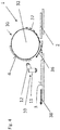
- FIG. 1 shows a first embodiment of an exposure device 1 in a schematic representation.
- the exposure device 1 comprises a first exposure unit 10 and a transport unit 30.
- the transport unit 30 comprises a drum 32 which transports plate-shaped material 2, for example a printing element.
- an endless conveyor belt can be provided instead of the drum 32.
- the transport unit 30 can optionally also comprise further elements.
- a tray 40 and transport rollers 34 are provided in addition to the illustrated embodiment.
- the shelf 40 can also be configured as a conveyor belt in further design variants.
- the tray 40 is composed of several sub-units and is interrupted at two areas 42 and 44.
- the plate-shaped material 2 comprises a first side 3, which in the embodiment 1 represents the underside of the plate-shaped material 2, and a second side 4, which in the illustrated embodiment represents the upper side of the plate-shaped material 2.
- the first exposure unit 10 is designed as a UV light source, for example as an LED strip with a large number of UV LEDs. Furthermore, the first exposure unit 10 is designed to be rotatable, so that it can be rotated about an axis of rotation 14. By rotating the first exposure unit 10 about the axis of rotation 14, the first exposure unit 10 can assume several positions, wherein the first exposure unit 10 can assume at least a first position 11 and a second position 12. In the in Figure 1 In the illustrated embodiment, the first exposure unit 10 is arranged below the tray 40 or the conveyor belt, the tray 40 or the conveyor belt being interrupted in an area 42 which is directly above the first exposure unit 10. The first side 3 of the plate-shaped material 2, which otherwise rests on the shelf 40 or the conveyor belt, is accessible from below through the interrupted area 42 of the tray 40 or the conveyor belt.
- the exposure device 1 shown is set up to expose both the first side 3 and the second side 4 of the plate-shaped material 2 using the first exposure unit 10.
- the plate-shaped material 2 is moved using the tray 40 configured as a conveyor belt and / or one of the conveyor rollers 34 in the direction marked with reference numeral 36.
- the plate-shaped material 2 is moved past the first exposure unit 10 while the first exposure unit 10 is in its first position 11.
- the first exposure unit 10 is preferably designed so that it can expose a rectangular area, one side of the rectangle being wider than the width of the plate-shaped material 2, so that the plate-shaped material 2 is exposed in its entire width at once through the first exposure unit 10 becomes. UV light from the first exposure unit 10 in the first position 11 passes through the interrupted area 42 onto the plate-shaped material 2.
- the first side 3 is preferably the rear side of the flexographic printing element, so that in the first step a rear side exposure is carried out by the exposure unit 10 in the first position 11.
- the illustrated device 1 can continuously transport it along the direction marked with the arrow 36.
- the transport can be carried out discontinuously, with a partial area of the plate-shaped material 2 being transported into the viewing area of the first exposure unit 10, after which the transport is stopped, this partial area is exposed and then the plate-shaped material 2 is transported further to the next partial area to expose.
- the plate-shaped material 2 is transported to the drum 32 and received on the drum 32, the plate-shaped material 2 rotating together with the drum 32 as indicated by the arrow 37.
- the drum 32 is arranged below the tray 40 or the conveyor belt in such a way that the plate-shaped material 2 is placed on the drum 32 from above through a further interruption 44 in the tray 40 or the conveyor belt and then picked up on the drum 32.
- the drum 32 for receiving the plate-shaped material 2 comprises at least one fastening device, which is designed, for example, as a vacuum suction fastening, with the aid of punched holes, or punching or clamping.
- openings are provided on the surface of the drum 32, via which the plate-shaped material 2 can be fixed by a negative pressure.
- the first exposure unit 10 is moved from the first position 11 to its second position 12 by rotating about the axis of rotation 14 and now points to the drum 32.
- the plate-shaped material 2 is again guided past the first exposure unit 10, whereby now the second side 4 of the plate-shaped material 2 faces the first exposure unit 10 and is exposed by the first exposure unit 10.
- the first exposure unit 10 is moved back into its first position 11 so that it is available for exposing the first side 3 of a further plate-shaped material.
- the second side 4 is preferably the front side of the flexographic printing element.
- an imaging unit 50 for writing a mask on the plate-shaped material 2 is also provided.
- the imaging unit 50 points in the direction of the drum 32 so that the mask can be written while the plate-shaped material 2 is continuously or discontinuously guided past the imaging unit 50 by rotating the drum 32.
- the imaging unit 50 is arranged in the second position 12 in front of the first exposure unit 10, as seen in the transport direction, compare arrow 37. In this way, the mask used for an imagewise exposure of the second side 4 is produced shortly before the exposure by the first exposure unit 10 in the second position 12.
- the imaging unit 50 can be, for example, a laser system with which a laser-ablatable mask layer of the plate-shaped material 2 is selectively removed.
- the plate-shaped material 2 is detached from the drum 32 along the direction indicated by the arrow 38.
- a fastening device that may be present on the drum 32 releases the plate-shaped material 2.
- the plate-shaped material 2 is placed again on the tray 40 or the conveyor belt and transported out of the exposure device 1.
- the plate-shaped material 2 can then be post-treated in further devices. If the exposure device 1 is part of an overall device for the production of printing forms, it can be transferred to the next treatment device, in particular the plate-shaped material 2 can be transferred to a developer or to a washer.
- FIG. 3 shows a second embodiment of the exposure device 1 which is similar to that with reference to FIG Figure 1
- the first embodiment described a first exposure unit 10 and a transport unit 30.
- the transport unit 30 comprises a drum 32.
- the transport unit 30 in the in FIG Figure 2 The illustrated embodiment has a tray 40 designed as a conveyor belt.
- both the first exposure unit 10 and the drum 32 are arranged above the tray 40 or the conveyor belt. Furthermore, no interruption of the tray 40 is provided in the area of the first exposure unit 10.
- the plate-shaped material 2 For the double-sided exposure of the plate-shaped material 2, provision is made in a first step for the plate-shaped material 2 to be guided past the first exposure unit 10, which is located in the first position 11, in the direction indicated by the arrow 36.
- the first side 3 of the plate-shaped material 2 is exposed. Again, the exposure can be continuous or discontinuous. Since the first exposure unit 10 is located above the tray 40 or the conveyor belt, no interruption of the tray 40 or the conveyor belt is necessary in the area of the first exposure unit 10, since the side of the plate-shaped material 2 lying on the conveyor belt 40 is not exposed .
- the plate-shaped material 2 After exposure, the plate-shaped material 2 is moved further towards the drum 32 in the direction indicated by the arrow 36.
- the drum 32 is also arranged above the level of the tray 40 or the conveyor belt, so that the plate-shaped material 2 on the underside of the drum 32 hits the surface of the drum 32 and is arranged on the surface of the drum 32.
- the plate-shaped material 2 received on the drum 32 then circulates together with the rotating drum 32.
- the orbital movement is indicated by arrow 37.
- the first exposure unit 10 is moved into the second position 12 in which it is now aligned with the drum 32.
- the plate-shaped material 2 with its second side 4 is moved past the first exposure unit 10 in the second position 12 and exposed. Again, this exposure process can take place continuously or discontinuously. If several exposures are required, further exposures can be carried out with further revolutions of the drum 32.
- an additional imaging unit can be provided which, while the plate-shaped material 2 is received on the drum 32, writes a mask in the plate-shaped material 2 before moving past the first exposure unit 10 in the second position 12.
- the plate-shaped material 2 is detached from the drum 32 along the direction indicated by the arrow 38, a fastening device that may be present on the drum 32 releasing the plate-shaped material 2.
- the plate-shaped material 2 is placed again on the tray 40 or the conveyor belt and transported out of the exposure device 1.
- the plate-shaped material can then be post-treated in further devices. If the exposure device 1 is part of an overall device for the production of printing forms, it can be transferred to the next treatment device, in particular the plate-shaped material 2 can be transferred to a developer or to a washer.
- the exposure device can additionally comprise a transfer unit with appropriate transport means.
- FIG 3 a third embodiment of the exposure device 1 is shown. Its structure corresponds to that with reference to Figure 1 described first embodiment, however, the plate-shaped material 2 passes through the exposure device 1 in the reverse direction.
- the first exposure unit 10 is in its second position 12 and the plate-shaped material 2 is placed on the drum 32 from above via the tray 40 or the conveyor belt in the direction indicated by the arrow 36 and then on the drum 32 added so that the plate-shaped material 2 rotates with the drum 32. While the plate-shaped material 2 is guided past the first exposure unit 10 in the second position 12, the second side 4 is exposed by the first exposure unit 10. Again, the exposure can be continuous or discontinuous. If several exposures are required, further exposures can be carried out with further revolutions of the drum 32.
- the plate-shaped material 2 is detached from the drum 32 and, as indicated by the arrow with reference numeral 37, is placed on the tray 40 or the conveyor belt.
- the first exposure unit 10 is moved into its first position 11.
- the first side 3 of the plate-shaped material 3 is exposed from below through an interrupted region 42 by the first exposure unit 10 in the first position 11.
- the plate-shaped material 2 is moved continuously or discontinuously, depending on the execution of the exposure process, along the direction marked with the arrow 38 and then transported out of the exposure device 1.
- the first exposure unit 10 is moved back into the second position 12 so that it is ready for a further exposure of the second side of a further plate-shaped material.
- the plate-shaped material 2 can be post-treated in further devices. If the exposure device 1 is part of an overall device for the production of printing forms, it can be transferred to the next treatment device, in particular the plate-shaped material 2 can be transferred to a developer or to a washer.
- FIG 4 a fourth embodiment of the exposure device 1 is shown. Its structure corresponds to that with reference to Figure 2 described second embodiment, but the plate-shaped material 2 passes through the exposure device 1 in the opposite direction.
- the first exposure unit 10 is in its second position 12 and the plate-shaped material 2 is brought up to the drum 32 from below via the tray 40 or the conveyor belt in the direction indicated by the arrow 36 and then onto the drum 32 added so that the plate-shaped material 2 rotates with the drum 32. While the plate-shaped material 2 is guided past the first exposure unit 10 in the second position 12, the second side 4 is exposed by the first exposure unit 10. Again, the exposure can be continuous or done discontinuously. If several exposures are required, further exposures can be carried out with further revolutions of the drum 32.
- the plate-shaped material 2 is detached from the drum 32 and, as indicated by the arrow with reference numeral 37, is placed on the tray 40 or the conveyor belt.
- the first exposure unit 10 is moved into its first position 11.
- the first side 3 of the plate-shaped material 3 is exposed from above by the first exposure unit 10 in the first position 11.
- the plate-shaped material 2 is moved continuously or discontinuously, depending on the execution of the exposure process, along the direction marked with the arrow 38 and then transported out of the exposure device 1.
- the first exposure unit 10 is moved back into the second position 12 so that it is ready for a further exposure of the second side of a further plate-shaped material.
- the plate-shaped material 2 can be post-treated in further devices. If the exposure device 1 is part of an overall device for the production of printing forms, it can be transferred to the next treatment device, in particular the plate-shaped material 2 can be transferred to a developer or to a washer.
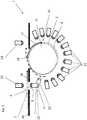
- FIG. 5 a fifth embodiment of the exposure device 1 is shown. Its structure corresponds to that with reference to Figure 1 described first embodiment, but additional exposure units 20, 22, 24 are provided.
- the further exposure units 20, 22, 24 are optional, so that, depending on the embodiment variant, only one further exposure unit 20, 22, 24 or only some of the illustrated further exposure units 20, 22, 24 are arranged.
- a further exposure unit 22 is arranged opposite the first exposure unit 10 in the first position 11 so that it can expose the second side 4 of the plate-shaped material 2, while the first exposure unit 10 in the first position 11 exposes the first side 3.
- Further exposure units 20 are also arranged distributed around the drum 32, the further exposure units 20 each pointing towards the drum 32. In this way, exposure of the second side 4 of the plate-shaped material is possible by means of the further exposure units 20 while this is being received on the drum 32.
- a plurality of further exposure units 20 are preferably distributed around the drum 32 in such a way that the entire surface of the second side 4 of the plate-shaped material 2 can be exposed at once even when the drum 32 is at rest.
- a further exposure unit 24 is arranged after the drum 32, as seen in the transport direction 38, above the tray 40 or the transport belt. A further exposure of the second side 4 of the plate-shaped material 2 can take place via the further exposure unit 24, which is followed by an exposure of the second side 4 by the first exposure unit 10 in the second position 12.
- the further exposure units 20, 22, 24 can of course also be used with the with reference to the Figures 2 to 4 described embodiments of the exposure device are combined.
Landscapes
- Physics & Mathematics (AREA)
- General Physics & Mathematics (AREA)
- Engineering & Computer Science (AREA)
- Optics & Photonics (AREA)
- Plasma & Fusion (AREA)
- Manufacturing & Machinery (AREA)
- Exposure And Positioning Against Photoresist Photosensitive Materials (AREA)
- Manufacture Or Reproduction Of Printing Formes (AREA)
- Photosensitive Polymer And Photoresist Processing (AREA)
Applications Claiming Priority (2)
| Application Number | Priority Date | Filing Date | Title |
|---|---|---|---|
| EP16200954 | 2016-11-28 | ||
| PCT/EP2017/080523 WO2018096144A1 (de) | 2016-11-28 | 2017-11-27 | Belichtungsvorrichtung und verfahren zur belichtung von plattenförmigen materialien |
Publications (2)
| Publication Number | Publication Date |
|---|---|
| EP3545360A1 EP3545360A1 (de) | 2019-10-02 |
| EP3545360B1 true EP3545360B1 (de) | 2021-03-17 |
Family
ID=57406176
Family Applications (1)
| Application Number | Title | Priority Date | Filing Date |
|---|---|---|---|
| EP17811248.8A Active EP3545360B1 (de) | 2016-11-28 | 2017-11-27 | Belichtungsvorrichtung und verfahren zur belichtung von plattenförmigen materialien |
Country Status (5)
| Country | Link |
|---|---|
| US (1) | US11007767B2 (zh) |
| EP (1) | EP3545360B1 (zh) |
| JP (1) | JP7155120B2 (zh) |
| CN (1) | CN109997082B (zh) |
| WO (1) | WO2018096144A1 (zh) |
Families Citing this family (3)
| Publication number | Priority date | Publication date | Assignee | Title |
|---|---|---|---|---|
| US10732507B2 (en) | 2015-10-26 | 2020-08-04 | Esko-Graphics Imaging Gmbh | Process and apparatus for controlled exposure of flexographic printing plates and adjusting the floor thereof |
| WO2020239665A1 (en) | 2019-05-30 | 2020-12-03 | Esko-Graphics Imaging Gmbh | Process and apparatus for automatic measurement of density of photopolymer printing plates |
| NL2025875B1 (en) * | 2020-06-19 | 2022-02-17 | Xeikon Prepress Nv | Apparatus and method for exposure of relief precursors |
Family Cites Families (21)
| Publication number | Priority date | Publication date | Assignee | Title |
|---|---|---|---|---|
| US5262275A (en) | 1992-08-07 | 1993-11-16 | E. I. Du Pont De Nemours And Company | Flexographic printing element having an IR ablatable layer and process for making a flexographic printing plate |
| JPH10333337A (ja) * | 1997-04-01 | 1998-12-18 | Okamoto Giken:Kk | 露光装置 |
| EP1069475B1 (en) | 1999-07-13 | 2002-09-18 | BASF Drucksysteme GmbH | Flexographic printing element comprising an IR-ablatable layer with high sensitivity |
| US6211942B1 (en) * | 2000-03-10 | 2001-04-03 | Howa Machinery Ltd. | Double-sided exposure system |
| JP3756882B2 (ja) | 2003-02-20 | 2006-03-15 | 株式会社東芝 | 情報処理装置及び情報処理方法 |
| DE102007006378A1 (de) | 2007-02-08 | 2008-08-14 | Flint Group Germany Gmbh | Fotopolymerisierbare zylindrische endlos-nahtlose Flexodruckelemente und daraus hergestellte harte Flexodruckformen |
| DK3054349T3 (en) * | 2007-05-08 | 2019-01-14 | Esko Graphics Imaging Gmbh | LIGHTING PRESSURE PLATES USING LIGHTING DIODES |
| DE102008024214A1 (de) | 2008-05-19 | 2009-11-26 | Flint Group Germany Gmbh | Fotopolymerisierbare Flexodruckelemente für den Druck mit UV-Farben |
| US8578854B2 (en) | 2008-05-23 | 2013-11-12 | Esko-Graphics Imaging Gmbh | Curing of photo-curable printing plates using a light tunnel of mirrored walls and having a polygonal cross-section like a kaleidoscope |
| US8034540B2 (en) * | 2008-07-31 | 2011-10-11 | Eastman Kodak Company | System and method employing secondary back exposure of flexographic plate |
| US8820234B2 (en) | 2009-10-30 | 2014-09-02 | Esko-Graphics Imaging Gmbh | Curing of photo-curable printing plates with flat tops or round tops by variable speed exposure |
| DE102010031527A1 (de) * | 2010-07-19 | 2012-01-19 | Flint Group Germany Gmbh | Verfahren zur Herstellung von Flexodruckformen umfassend die Bestrahlung mit UV-LEDs |
| US8551688B2 (en) | 2011-04-21 | 2013-10-08 | Ryan W. Vest | Photosensitive resin laminate and thermal processing of the same |
| US8790864B2 (en) | 2012-08-27 | 2014-07-29 | Kyle P. Baldwin | Method of improving print performance in flexographic printing plates |
| JP6526018B2 (ja) * | 2013-09-30 | 2019-06-05 | フリント、グループ、ジャーマニー、ゲゼルシャフト、ミット、ベシュレンクテル、ハフツング | フレキソ印刷版を一列に並んで生産する装置及び方法 |
| KR20160073415A (ko) * | 2013-10-22 | 2016-06-24 | 어플라이드 머티어리얼스, 인코포레이티드 | 능동 정렬을 이용하는 롤 투 롤 마스크-없는 리소그래피 |
| US9256129B2 (en) * | 2014-02-19 | 2016-02-09 | Macdermid Printing Solutions, Llc | Method for creating surface texture on flexographic printing elements |
| WO2016054150A1 (en) | 2014-09-30 | 2016-04-07 | Sensor Electronic Technology, Inc. | Movable ultraviolet radiation source |
| EP3035123A1 (de) | 2014-12-17 | 2016-06-22 | Flint Group Germany GmbH | Verfahren zur Herstellung von Flexodruckformen durch mehrfache Belichtung mit UV-LEDs |
| EP3054352B1 (de) * | 2015-02-06 | 2017-11-08 | Flint Group Germany GmbH | Automatisierte uv-led belichtung von flexodruckplatten |
| KR101700036B1 (ko) * | 2015-06-23 | 2017-02-08 | 아주하이텍(주) | 드럼형 LDI In-Line 양면 노광장치 |
-
2017
- 2017-11-27 JP JP2019528556A patent/JP7155120B2/ja active Active
- 2017-11-27 WO PCT/EP2017/080523 patent/WO2018096144A1/de active Search and Examination
- 2017-11-27 EP EP17811248.8A patent/EP3545360B1/de active Active
- 2017-11-27 CN CN201780073217.7A patent/CN109997082B/zh active Active
- 2017-11-27 US US16/463,024 patent/US11007767B2/en active Active
Non-Patent Citations (1)
| Title |
|---|
| None * |
Also Published As
| Publication number | Publication date |
|---|---|
| US11007767B2 (en) | 2021-05-18 |
| JP7155120B2 (ja) | 2022-10-18 |
| JP2020508476A (ja) | 2020-03-19 |
| EP3545360A1 (de) | 2019-10-02 |
| CN109997082A (zh) | 2019-07-09 |
| WO2018096144A1 (de) | 2018-05-31 |
| CN109997082B (zh) | 2021-11-16 |
| US20200023632A1 (en) | 2020-01-23 |
Similar Documents
| Publication | Publication Date | Title |
|---|---|---|
| EP3234696B1 (de) | Verfahren zur herstellung von flexodruckformen durch mehrfache belichtung mit uv-leds | |
| EP3054352B1 (de) | Automatisierte uv-led belichtung von flexodruckplatten | |
| EP2596404B1 (de) | Uv-led-bestrahlung umfassendes verfahren zur herstellung von flexodruckformen | |
| EP3545360B1 (de) | Belichtungsvorrichtung und verfahren zur belichtung von plattenförmigen materialien | |
| EP1800187B1 (de) | Verfahren und vorrichtung zur herstellung von fotopolymerisierbaren, zylindrischen, endlos-nahtlosen flexodruckelementen | |
| DE69602699T2 (de) | Verfahren und Geräte zur Herstellung von zylindrischen lichtempfindlichen Elementen | |
| EP3052988B1 (de) | Vorrichtung und verfahren zur in-line herstellung von flexodruckplatten | |
| EP1570316B1 (de) | Vorrichtung und verfahren zur herstellung von flexodruckplatten für den zeitungsdruck mittels digitaler bebilderung | |
| DE102018127936A1 (de) | Vorrichtung, Druckmaschine und Verfahren zur Herstellung eines Sicherheitselementes auf einem Substrat | |
| EP3721293B1 (de) | Verfahren zur kennzeichnung eines reliefvorläufers zur herstellung einer reliefstruktur | |
| DE69319533T2 (de) | Methode zum Perforieren einer Thermo-Siebdruckschablone | |
| DE202018006543U1 (de) | Einrichtung zum Anpassen des Bodens einer flexografischen Druckplatte in einem gesteuerten bzw. geregelten Belichtungssystem | |
| DE10258421A1 (de) | Nicht-permanente tintengestrahlte flexographische Maske | |
| DE102007063603B4 (de) | Verfahren und Vorrichtung zur Herstellung von keramischen Folien mit UV-LED | |
| DE10318042A1 (de) | Verfahren zur Herstellung von fotopolymerisierbaren, zylindrischen, endlos-nahtlosen Flexodruckelementen und deren Verwendung zur Herstellung zylindrischer Flexodruckformen | |
| EP1014201A2 (de) | Verfahren zur Herstellung von grossformatigen Verbund-Reliefdruckformen durch Laserpositionierung und anschliessende Bebilderung mittels Laser | |
| WO2006056413A2 (de) | Verfahren zur herstellung von flexodruckformen sowie dazu geeignetes flexodruckelement | |
| DE1499376A1 (de) | Locher- bzw. Abtragvorrichtung fuer schichtfoermige Medien | |
| DE102015204980B4 (de) | Druckmaschine mit zumindest einem Selektivtrockner | |
| DE69835160T2 (de) | Komposit-reliefdruckplatten | |
| EP2275870A1 (de) | Verfahren zum Herstellen von zylinderförmigen Flexodruckplatten mittels digitaler Bebilderung | |
| EP3523696B1 (de) | Verbundplatte mit sperrschicht und verfahren zur herstellung einer hochdruckplatte | |
| DE102011005908A1 (de) | Drucksysteme mit fortschreitendem Bildtransfer und fortschreitender Strahlungsenergiebeaufschlagung von Bildern für das Drucken mit Mehrfachdurchlauf, für entsprechende Druckvorrichtungen und zugehörige Verfahren | |
| EP1154326A1 (de) | Verfahren und Vorrichtung zur Herstellung von Druckplatten | |
| EP3152621A1 (de) | Schnell trockenbare flexodruckelemente |
Legal Events
| Date | Code | Title | Description |
|---|---|---|---|
| STAA | Information on the status of an ep patent application or granted ep patent |
Free format text: STATUS: UNKNOWN |
|
| STAA | Information on the status of an ep patent application or granted ep patent |
Free format text: STATUS: THE INTERNATIONAL PUBLICATION HAS BEEN MADE |
|
| PUAI | Public reference made under article 153(3) epc to a published international application that has entered the european phase |
Free format text: ORIGINAL CODE: 0009012 |
|
| STAA | Information on the status of an ep patent application or granted ep patent |
Free format text: STATUS: REQUEST FOR EXAMINATION WAS MADE |
|
| 17P | Request for examination filed |
Effective date: 20190628 |
|
| AK | Designated contracting states |
Kind code of ref document: A1 Designated state(s): AL AT BE BG CH CY CZ DE DK EE ES FI FR GB GR HR HU IE IS IT LI LT LU LV MC MK MT NL NO PL PT RO RS SE SI SK SM TR |
|
| AX | Request for extension of the european patent |
Extension state: BA ME |
|
| DAV | Request for validation of the european patent (deleted) | ||
| DAX | Request for extension of the european patent (deleted) | ||
| GRAP | Despatch of communication of intention to grant a patent |
Free format text: ORIGINAL CODE: EPIDOSNIGR1 |
|
| STAA | Information on the status of an ep patent application or granted ep patent |
Free format text: STATUS: GRANT OF PATENT IS INTENDED |
|
| INTG | Intention to grant announced |
Effective date: 20201015 |
|
| GRAS | Grant fee paid |
Free format text: ORIGINAL CODE: EPIDOSNIGR3 |
|
| GRAA | (expected) grant |
Free format text: ORIGINAL CODE: 0009210 |
|
| STAA | Information on the status of an ep patent application or granted ep patent |
Free format text: STATUS: THE PATENT HAS BEEN GRANTED |
|
| AK | Designated contracting states |
Kind code of ref document: B1 Designated state(s): AL AT BE BG CH CY CZ DE DK EE ES FI FR GB GR HR HU IE IS IT LI LT LU LV MC MK MT NL NO PL PT RO RS SE SI SK SM TR |
|
| REG | Reference to a national code |
Ref country code: GB Ref legal event code: FG4D Free format text: NOT ENGLISH |
|
| REG | Reference to a national code |
Ref country code: CH Ref legal event code: EP |
|
| REG | Reference to a national code |
Ref country code: DE Ref legal event code: R096 Ref document number: 502017009759 Country of ref document: DE |
|
| REG | Reference to a national code |
Ref country code: IE Ref legal event code: FG4D Free format text: LANGUAGE OF EP DOCUMENT: GERMAN |
|
| REG | Reference to a national code |
Ref country code: AT Ref legal event code: REF Ref document number: 1372795 Country of ref document: AT Kind code of ref document: T Effective date: 20210415 |
|
| REG | Reference to a national code |
Ref country code: LT Ref legal event code: MG9D |
|
| REG | Reference to a national code |
Ref country code: SK Ref legal event code: T3 Ref document number: E 37352 Country of ref document: SK |
|
| PG25 | Lapsed in a contracting state [announced via postgrant information from national office to epo] |
Ref country code: NO Free format text: LAPSE BECAUSE OF FAILURE TO SUBMIT A TRANSLATION OF THE DESCRIPTION OR TO PAY THE FEE WITHIN THE PRESCRIBED TIME-LIMIT Effective date: 20210617 Ref country code: HR Free format text: LAPSE BECAUSE OF FAILURE TO SUBMIT A TRANSLATION OF THE DESCRIPTION OR TO PAY THE FEE WITHIN THE PRESCRIBED TIME-LIMIT Effective date: 20210317 Ref country code: GR Free format text: LAPSE BECAUSE OF FAILURE TO SUBMIT A TRANSLATION OF THE DESCRIPTION OR TO PAY THE FEE WITHIN THE PRESCRIBED TIME-LIMIT Effective date: 20210618 Ref country code: FI Free format text: LAPSE BECAUSE OF FAILURE TO SUBMIT A TRANSLATION OF THE DESCRIPTION OR TO PAY THE FEE WITHIN THE PRESCRIBED TIME-LIMIT Effective date: 20210317 Ref country code: BG Free format text: LAPSE BECAUSE OF FAILURE TO SUBMIT A TRANSLATION OF THE DESCRIPTION OR TO PAY THE FEE WITHIN THE PRESCRIBED TIME-LIMIT Effective date: 20210617 |
|
| REG | Reference to a national code |
Ref country code: NL Ref legal event code: MP Effective date: 20210317 |
|
| PG25 | Lapsed in a contracting state [announced via postgrant information from national office to epo] |
Ref country code: RS Free format text: LAPSE BECAUSE OF FAILURE TO SUBMIT A TRANSLATION OF THE DESCRIPTION OR TO PAY THE FEE WITHIN THE PRESCRIBED TIME-LIMIT Effective date: 20210317 Ref country code: LV Free format text: LAPSE BECAUSE OF FAILURE TO SUBMIT A TRANSLATION OF THE DESCRIPTION OR TO PAY THE FEE WITHIN THE PRESCRIBED TIME-LIMIT Effective date: 20210317 Ref country code: SE Free format text: LAPSE BECAUSE OF FAILURE TO SUBMIT A TRANSLATION OF THE DESCRIPTION OR TO PAY THE FEE WITHIN THE PRESCRIBED TIME-LIMIT Effective date: 20210317 |
|
| PG25 | Lapsed in a contracting state [announced via postgrant information from national office to epo] |
Ref country code: NL Free format text: LAPSE BECAUSE OF FAILURE TO SUBMIT A TRANSLATION OF THE DESCRIPTION OR TO PAY THE FEE WITHIN THE PRESCRIBED TIME-LIMIT Effective date: 20210317 |
|
| PG25 | Lapsed in a contracting state [announced via postgrant information from national office to epo] |
Ref country code: LT Free format text: LAPSE BECAUSE OF FAILURE TO SUBMIT A TRANSLATION OF THE DESCRIPTION OR TO PAY THE FEE WITHIN THE PRESCRIBED TIME-LIMIT Effective date: 20210317 Ref country code: EE Free format text: LAPSE BECAUSE OF FAILURE TO SUBMIT A TRANSLATION OF THE DESCRIPTION OR TO PAY THE FEE WITHIN THE PRESCRIBED TIME-LIMIT Effective date: 20210317 Ref country code: CZ Free format text: LAPSE BECAUSE OF FAILURE TO SUBMIT A TRANSLATION OF THE DESCRIPTION OR TO PAY THE FEE WITHIN THE PRESCRIBED TIME-LIMIT Effective date: 20210317 Ref country code: SM Free format text: LAPSE BECAUSE OF FAILURE TO SUBMIT A TRANSLATION OF THE DESCRIPTION OR TO PAY THE FEE WITHIN THE PRESCRIBED TIME-LIMIT Effective date: 20210317 |
|
| PG25 | Lapsed in a contracting state [announced via postgrant information from national office to epo] |
Ref country code: IS Free format text: LAPSE BECAUSE OF FAILURE TO SUBMIT A TRANSLATION OF THE DESCRIPTION OR TO PAY THE FEE WITHIN THE PRESCRIBED TIME-LIMIT Effective date: 20210717 Ref country code: PL Free format text: LAPSE BECAUSE OF FAILURE TO SUBMIT A TRANSLATION OF THE DESCRIPTION OR TO PAY THE FEE WITHIN THE PRESCRIBED TIME-LIMIT Effective date: 20210317 Ref country code: PT Free format text: LAPSE BECAUSE OF FAILURE TO SUBMIT A TRANSLATION OF THE DESCRIPTION OR TO PAY THE FEE WITHIN THE PRESCRIBED TIME-LIMIT Effective date: 20210719 Ref country code: RO Free format text: LAPSE BECAUSE OF FAILURE TO SUBMIT A TRANSLATION OF THE DESCRIPTION OR TO PAY THE FEE WITHIN THE PRESCRIBED TIME-LIMIT Effective date: 20210317 |
|
| REG | Reference to a national code |
Ref country code: DE Ref legal event code: R097 Ref document number: 502017009759 Country of ref document: DE |
|
| PLBE | No opposition filed within time limit |
Free format text: ORIGINAL CODE: 0009261 |
|
| STAA | Information on the status of an ep patent application or granted ep patent |
Free format text: STATUS: NO OPPOSITION FILED WITHIN TIME LIMIT |
|
| PG25 | Lapsed in a contracting state [announced via postgrant information from national office to epo] |
Ref country code: ES Free format text: LAPSE BECAUSE OF FAILURE TO SUBMIT A TRANSLATION OF THE DESCRIPTION OR TO PAY THE FEE WITHIN THE PRESCRIBED TIME-LIMIT Effective date: 20210317 Ref country code: DK Free format text: LAPSE BECAUSE OF FAILURE TO SUBMIT A TRANSLATION OF THE DESCRIPTION OR TO PAY THE FEE WITHIN THE PRESCRIBED TIME-LIMIT Effective date: 20210317 Ref country code: AL Free format text: LAPSE BECAUSE OF FAILURE TO SUBMIT A TRANSLATION OF THE DESCRIPTION OR TO PAY THE FEE WITHIN THE PRESCRIBED TIME-LIMIT Effective date: 20210317 |
|
| 26N | No opposition filed |
Effective date: 20211220 |
|
| PG25 | Lapsed in a contracting state [announced via postgrant information from national office to epo] |
Ref country code: SI Free format text: LAPSE BECAUSE OF FAILURE TO SUBMIT A TRANSLATION OF THE DESCRIPTION OR TO PAY THE FEE WITHIN THE PRESCRIBED TIME-LIMIT Effective date: 20210317 |
|
| PG25 | Lapsed in a contracting state [announced via postgrant information from national office to epo] |
Ref country code: IS Free format text: LAPSE BECAUSE OF FAILURE TO SUBMIT A TRANSLATION OF THE DESCRIPTION OR TO PAY THE FEE WITHIN THE PRESCRIBED TIME-LIMIT Effective date: 20210717 |
|
| PG25 | Lapsed in a contracting state [announced via postgrant information from national office to epo] |
Ref country code: MC Free format text: LAPSE BECAUSE OF FAILURE TO SUBMIT A TRANSLATION OF THE DESCRIPTION OR TO PAY THE FEE WITHIN THE PRESCRIBED TIME-LIMIT Effective date: 20210317 |
|
| REG | Reference to a national code |
Ref country code: CH Ref legal event code: PL |
|
| PG25 | Lapsed in a contracting state [announced via postgrant information from national office to epo] |
Ref country code: LU Free format text: LAPSE BECAUSE OF NON-PAYMENT OF DUE FEES Effective date: 20211127 Ref country code: BE Free format text: LAPSE BECAUSE OF NON-PAYMENT OF DUE FEES Effective date: 20211130 |
|
| REG | Reference to a national code |
Ref country code: BE Ref legal event code: MM Effective date: 20211130 |
|
| PG25 | Lapsed in a contracting state [announced via postgrant information from national office to epo] |
Ref country code: LI Free format text: LAPSE BECAUSE OF NON-PAYMENT OF DUE FEES Effective date: 20211130 Ref country code: CH Free format text: LAPSE BECAUSE OF NON-PAYMENT OF DUE FEES Effective date: 20211130 |
|
| PG25 | Lapsed in a contracting state [announced via postgrant information from national office to epo] |
Ref country code: IE Free format text: LAPSE BECAUSE OF NON-PAYMENT OF DUE FEES Effective date: 20211127 |
|
| PG25 | Lapsed in a contracting state [announced via postgrant information from national office to epo] |
Ref country code: CY Free format text: LAPSE BECAUSE OF FAILURE TO SUBMIT A TRANSLATION OF THE DESCRIPTION OR TO PAY THE FEE WITHIN THE PRESCRIBED TIME-LIMIT Effective date: 20210317 |
|
| P01 | Opt-out of the competence of the unified patent court (upc) registered |
Effective date: 20230529 |
|
| PG25 | Lapsed in a contracting state [announced via postgrant information from national office to epo] |
Ref country code: HU Free format text: LAPSE BECAUSE OF FAILURE TO SUBMIT A TRANSLATION OF THE DESCRIPTION OR TO PAY THE FEE WITHIN THE PRESCRIBED TIME-LIMIT; INVALID AB INITIO Effective date: 20171127 |
|
| REG | Reference to a national code |
Ref country code: SK Ref legal event code: TC4A Ref document number: E 37352 Country of ref document: SK Owner name: XSYS GERMANY GMBH, 77731 WILLSTAETT, DE Effective date: 20230712 |
|
| REG | Reference to a national code |
Ref country code: AT Ref legal event code: MM01 Ref document number: 1372795 Country of ref document: AT Kind code of ref document: T Effective date: 20221127 |
|
| PGFP | Annual fee paid to national office [announced via postgrant information from national office to epo] |
Ref country code: SK Payment date: 20231121 Year of fee payment: 7 |
|
| PGFP | Annual fee paid to national office [announced via postgrant information from national office to epo] |
Ref country code: GB Payment date: 20231123 Year of fee payment: 7 |
|
| PG25 | Lapsed in a contracting state [announced via postgrant information from national office to epo] |
Ref country code: AT Free format text: LAPSE BECAUSE OF NON-PAYMENT OF DUE FEES Effective date: 20221127 |
|
| PGFP | Annual fee paid to national office [announced via postgrant information from national office to epo] |
Ref country code: IT Payment date: 20231124 Year of fee payment: 7 Ref country code: FR Payment date: 20231120 Year of fee payment: 7 Ref country code: DE Payment date: 20231121 Year of fee payment: 7 |
|
| PG25 | Lapsed in a contracting state [announced via postgrant information from national office to epo] |
Ref country code: MK Free format text: LAPSE BECAUSE OF FAILURE TO SUBMIT A TRANSLATION OF THE DESCRIPTION OR TO PAY THE FEE WITHIN THE PRESCRIBED TIME-LIMIT Effective date: 20210317 |
|
| REG | Reference to a national code |
Ref country code: DE Ref legal event code: R081 Ref document number: 502017009759 Country of ref document: DE Owner name: XSYS GERMANY GMBH, DE Free format text: FORMER OWNER: FLINT GROUP GERMANY GMBH, 70469 STUTTGART, DE |
|
| PG25 | Lapsed in a contracting state [announced via postgrant information from national office to epo] |
Ref country code: TR Free format text: LAPSE BECAUSE OF FAILURE TO SUBMIT A TRANSLATION OF THE DESCRIPTION OR TO PAY THE FEE WITHIN THE PRESCRIBED TIME-LIMIT Effective date: 20210317 |