EP3545320B1 - Verfahren und anordnung zur klassifizierung eines spannungsfehlerzustands in einem elektrischen speichersystem - Google Patents
Verfahren und anordnung zur klassifizierung eines spannungsfehlerzustands in einem elektrischen speichersystem Download PDFInfo
- Publication number
- EP3545320B1 EP3545320B1 EP16801471.0A EP16801471A EP3545320B1 EP 3545320 B1 EP3545320 B1 EP 3545320B1 EP 16801471 A EP16801471 A EP 16801471A EP 3545320 B1 EP3545320 B1 EP 3545320B1
- Authority
- EP
- European Patent Office
- Prior art keywords
- cell
- voltage
- battery
- severity
- fault condition
- Prior art date
- Legal status (The legal status is an assumption and is not a legal conclusion. Google has not performed a legal analysis and makes no representation as to the accuracy of the status listed.)
- Active
Links
Images

Classifications
-
- G—PHYSICS
- G01—MEASURING; TESTING
- G01R—MEASURING ELECTRIC VARIABLES; MEASURING MAGNETIC VARIABLES
- G01R31/00—Arrangements for testing electric properties; Arrangements for locating electric faults; Arrangements for electrical testing characterised by what is being tested not provided for elsewhere
- G01R31/36—Arrangements for testing, measuring or monitoring the electrical condition of accumulators or electric batteries, e.g. capacity or state of charge [SoC]
- G01R31/3644—Constructional arrangements
- G01R31/3648—Constructional arrangements comprising digital calculation means, e.g. for performing an algorithm
-
- B—PERFORMING OPERATIONS; TRANSPORTING
- B60—VEHICLES IN GENERAL
- B60L—PROPULSION OF ELECTRICALLY-PROPELLED VEHICLES; SUPPLYING ELECTRIC POWER FOR AUXILIARY EQUIPMENT OF ELECTRICALLY-PROPELLED VEHICLES; ELECTRODYNAMIC BRAKE SYSTEMS FOR VEHICLES IN GENERAL; MAGNETIC SUSPENSION OR LEVITATION FOR VEHICLES; MONITORING OPERATING VARIABLES OF ELECTRICALLY-PROPELLED VEHICLES; ELECTRIC SAFETY DEVICES FOR ELECTRICALLY-PROPELLED VEHICLES
- B60L58/00—Methods or circuit arrangements for monitoring or controlling batteries or fuel cells, specially adapted for electric vehicles
- B60L58/10—Methods or circuit arrangements for monitoring or controlling batteries or fuel cells, specially adapted for electric vehicles for monitoring or controlling batteries
- B60L58/12—Methods or circuit arrangements for monitoring or controlling batteries or fuel cells, specially adapted for electric vehicles for monitoring or controlling batteries responding to state of charge [SoC]
-
- H—ELECTRICITY
- H01—ELECTRIC ELEMENTS
- H01M—PROCESSES OR MEANS, e.g. BATTERIES, FOR THE DIRECT CONVERSION OF CHEMICAL ENERGY INTO ELECTRICAL ENERGY
- H01M10/00—Secondary cells; Manufacture thereof
- H01M10/42—Methods or arrangements for servicing or maintenance of secondary cells or secondary half-cells
- H01M10/48—Accumulators combined with arrangements for measuring, testing or indicating the condition of cells, e.g. the level or density of the electrolyte
- H01M10/482—Accumulators combined with arrangements for measuring, testing or indicating the condition of cells, e.g. the level or density of the electrolyte for several batteries or cells simultaneously or sequentially
-
- G—PHYSICS
- G01—MEASURING; TESTING
- G01R—MEASURING ELECTRIC VARIABLES; MEASURING MAGNETIC VARIABLES
- G01R31/00—Arrangements for testing electric properties; Arrangements for locating electric faults; Arrangements for electrical testing characterised by what is being tested not provided for elsewhere
- G01R31/36—Arrangements for testing, measuring or monitoring the electrical condition of accumulators or electric batteries, e.g. capacity or state of charge [SoC]
- G01R31/374—Arrangements for testing, measuring or monitoring the electrical condition of accumulators or electric batteries, e.g. capacity or state of charge [SoC] with means for correcting the measurement for temperature or ageing
-
- G—PHYSICS
- G01—MEASURING; TESTING
- G01R—MEASURING ELECTRIC VARIABLES; MEASURING MAGNETIC VARIABLES
- G01R31/00—Arrangements for testing electric properties; Arrangements for locating electric faults; Arrangements for electrical testing characterised by what is being tested not provided for elsewhere
- G01R31/36—Arrangements for testing, measuring or monitoring the electrical condition of accumulators or electric batteries, e.g. capacity or state of charge [SoC]
- G01R31/382—Arrangements for monitoring battery or accumulator variables, e.g. SoC
- G01R31/3842—Arrangements for monitoring battery or accumulator variables, e.g. SoC combining voltage and current measurements
-
- G—PHYSICS
- G01—MEASURING; TESTING
- G01R—MEASURING ELECTRIC VARIABLES; MEASURING MAGNETIC VARIABLES
- G01R31/00—Arrangements for testing electric properties; Arrangements for locating electric faults; Arrangements for electrical testing characterised by what is being tested not provided for elsewhere
- G01R31/36—Arrangements for testing, measuring or monitoring the electrical condition of accumulators or electric batteries, e.g. capacity or state of charge [SoC]
- G01R31/396—Acquisition or processing of data for testing or for monitoring individual cells or groups of cells within a battery
-
- H—ELECTRICITY
- H01—ELECTRIC ELEMENTS
- H01M—PROCESSES OR MEANS, e.g. BATTERIES, FOR THE DIRECT CONVERSION OF CHEMICAL ENERGY INTO ELECTRICAL ENERGY
- H01M10/00—Secondary cells; Manufacture thereof
- H01M10/42—Methods or arrangements for servicing or maintenance of secondary cells or secondary half-cells
- H01M10/48—Accumulators combined with arrangements for measuring, testing or indicating the condition of cells, e.g. the level or density of the electrolyte
-
- H—ELECTRICITY
- H01—ELECTRIC ELEMENTS
- H01M—PROCESSES OR MEANS, e.g. BATTERIES, FOR THE DIRECT CONVERSION OF CHEMICAL ENERGY INTO ELECTRICAL ENERGY
- H01M10/00—Secondary cells; Manufacture thereof
- H01M10/42—Methods or arrangements for servicing or maintenance of secondary cells or secondary half-cells
- H01M10/425—Structural combination with electronic components, e.g. electronic circuits integrated to the outside of the casing
- H01M2010/4271—Battery management systems including electronic circuits, e.g. control of current or voltage to keep battery in healthy state, cell balancing
-
- H—ELECTRICITY
- H01—ELECTRIC ELEMENTS
- H01M—PROCESSES OR MEANS, e.g. BATTERIES, FOR THE DIRECT CONVERSION OF CHEMICAL ENERGY INTO ELECTRICAL ENERGY
- H01M10/00—Secondary cells; Manufacture thereof
- H01M10/42—Methods or arrangements for servicing or maintenance of secondary cells or secondary half-cells
- H01M10/425—Structural combination with electronic components, e.g. electronic circuits integrated to the outside of the casing
- H01M2010/4278—Systems for data transfer from batteries, e.g. transfer of battery parameters to a controller, data transferred between battery controller and main controller
-
- H—ELECTRICITY
- H01—ELECTRIC ELEMENTS
- H01M—PROCESSES OR MEANS, e.g. BATTERIES, FOR THE DIRECT CONVERSION OF CHEMICAL ENERGY INTO ELECTRICAL ENERGY
- H01M2220/00—Batteries for particular applications
- H01M2220/20—Batteries in motive systems, e.g. vehicle, ship, plane
Definitions
- the present invention relates to method and arrangement for classifying a voltage fault condition in a battery for a hybrid vehicle or electric vehicle.
- the invention also relates to a vehicle comprising such an arrangement.
- An internal combustion engine for example in the form of a gasoline engine or a diesel engine, offers high efficiency with relatively low fuel consumption.
- environmental concerns have caused an increase in development of more environmental-friendly power sources for vehicles.
- electrically operated vehicles has emerged as a promising alternative.
- a vehicle can be operated by means of an electric machine solely, or by means of an arrangement comprising both an electric machine and an internal combustion engine.
- the latter alternative is often referred to as a hybrid vehicle (HEV), and can for example be utilized in a manner in which an internal combustion engine is used for operating the vehicle while driving outside urban areas whereas the electric machine can be used in urban areas or in environments in which there is a need to limit the discharge of harmful pollutants such as carbon monoxide and oxides of nitrogen.
- HEV hybrid vehicle
- electric machines are operated by means of a storage system for electrical energy arranged in the vehicle, typically in the form of one or a plurality of battery unit(s) which is formed by a plurality of rechargeable battery cells and an associated control unit.
- plug-in hybrid electric vehicle uses an energy storage system with rechargeable batteries or another suitable energy source which can be restored into a condition involving a full charge through a connection to an external electric power supply, and may also be driven by e.g. a internal combustion engine to recharge the batteries.
- lithium-ion batteries are considered as the most appropriate battery technology for range, power, and recharging time.
- the battery When an electrically operated vehicle is operated, the battery need to be continuously monitored to avoid a breakdown of cells in the battery pack. This allows a battery controller to stop charge and discharge from a battery pack to protect the battery pack. Thereby, downtime and expensive maintenance or even replacement of the battery unit or a cell therein may be avoided, for example by automatically stopping the operation of the vehicle when the parameters of the battery unit indicate an error.
- Document EP2485293 discloses a battery system including: a battery module comprising a plurality of cell groups connected in series, each comprising a plurality of cells connected in series; a plurality of integrated circuits provided to corresponding each cell group of the battery module, that perform detection of terminal voltages of the cells in the corresponding each cell group, and that also perform diagnosis; and a battery controller that, along with issuing commands to the plurality of integrated circuits, also receives results of detection and results of diagnosis by the plurality of integrated circuits.
- the battery system comprises a writable non-volatile memory, and data is stored in the writable non-volatile memory specifying usage environment of the battery module, including a maximum voltage or a maximum current of the battery module and history data based upon operation history of the battery module.
- EP2337182 discloses a power supply device including a battery pack 10, and forcedly discharging circuits 20.
- the forcedly discharging circuits 20 are connected to the battery cells 2 in parallel so that, when a cell voltage of a battery cell is becomes higher than a predetermined voltage, this battery cell is forcedly discharged.
- Each heating control system comprises a heating device connected with the corresponding batteries and used for heating up the corresponding batteries, and a heating control circuit connected with both the heating device and the corresponding batteries and used for controlling the heating device to heat up the corresponding batteries.
- JP2006109540 shows a battery pack comprising a plurality of detection means 101a and 101b which detect individually the voltage of secondary batteries within each group among a plurality groups 10a and 10b which are made by dividing secondary batteries, connected in series in plural numbers, into a plurality of groups.
- a plurality of switch elements 102a, 102b, 103a and 103b are provided for every plural detection means which perform the control of breaking the charge current to the secondary batteries or the discharge currents from the secondary batteries in case that the voltage detected by any detection means is outside a specified range.
- a plurality of voltage limiting elements 104a, 104b, 105a and 105b is provided which limit the voltage to be applied to the switch elements in case that the voltage applied to the plurality of switch elements is not less than the specified voltage.
- a module management electronics may place battery modules in protective modes based upon the performance of each module, or battery cell therein, based on comparison to known or configurable specifications of the battery. For example, if the module management electronics detect a too high or low temperature in a battery module, the battery module may be placed in a permanent shutdown protective mode for later replacement. Further, the main controller of the battery array may determine the state of health (SOH) of the battery modules by looking at several parameters of the battery module. When the SOH of a battery module drops below a threshold SOH, the main controller may alert the user that the battery modules are in need of servicing.
- SOH state of health
- a method for classifying a voltage fault condition of a battery comprising a plurality of cells for a vehicle comprises:
- the present invention is based on the realization that the cell voltage of the cells of a battery may end up outside a predetermined voltage range due to several causes which need not be directly dangerous or damaging to the battery. Hence, permanently suspending operation of the battery pack or cell in question may not be necessary.
- the invention provides a quicker way identify the apparent cause of the voltage fault condition by performing at least one diagnostic test routine, based on the severity of the voltage fault condition. Thereby, a correct battery operation condition may be selected and adapted, based on the severity of the voltage fault condition and the cause, such that the battery is enabled to continue to operate the vehicle.
- the expression selecting and adapting a battery operation condition should be understood to comprise taking an action which reduces the severity, or eliminates the cause of the voltage fault condition.
- the present invention provides an improved manner of identifying the relevant cause, or causes, behind a voltage fault condition. Thereby, the cause may be identified with less operations and tests which are time and/or energy consuming.
- a predetermined voltage range for the cell may be e.g. a voltage range of 1V to 10V.
- a predetermined voltage range for the cell may be e.g. a voltage range of 1.0V to 5.0V, or 2.7V to 3.4V, or 2.7V to 4.0V.
- a voltage outside such a range may be utilized to determine that a voltage fault condition is present.
- the voltage range may depend on the chemistry of the cell, and also the power window and energy window that is required. Both the power window (i.e. the SOC window where the power requirement are met) and the energy window may influence the voltage range and thus the trigger conditions for a voltage fault condition. It should thus be understood that the present invention may be used to advantage with a wide range of batteries and battery cell chemistries.
- the method further comprises repeating the steps of the method for a portion of the cells of a battery. Stated differently, the method is repeatedly performed for a portion of the cells of the battery, or for all the cells of the battery in order to classify the voltage fault condition of the whole battery.
- the severity is increased if a voltage fault condition has occurred previously for the cell. This means that a less serious voltage fault condition may be classified as more severe if a voltage fault condition has occurred more than once. Thereby, more severe cause(s) and reason(s) behind the voltage fault condition may be identified even if the severity of the voltage fault condition is low. In another example, the severity may be decreased if no voltage fault condition has occurred previously.
- the expression historical data should be interpreted as data based on the previous performance of the battery and/or cells such as voltage fault conditions, or data based on previous performance of a battery and/or cells which are of similar make and/or type and installed in a similar vehicle. The data may be stored in a control unit, or may be retrieved using a wired or wireless network from a remote database.
- the step of classifying the severity of the voltage fault condition further comprises classifying the voltage fault condition to be of low severity, medium severity, high severity or breakdown severity.
- a low severity should be understood to mean that selecting and adapting a battery operation condition comprises adapting the battery itself, whereas for the medium severity, high severity and breakdown severity comprise adapting control parameters for the vehicle and vehicle control unit(s) in order to reduce the severity of the voltage fault condition.
- a certain cause leading to a voltage fault condition may be classified differently based on information relating to the vehicles previous action. Further, it is not always the battery control unit which measures and controls the power output from the battery.
- the vehicle control unit may exceed this limit due to actions of e.g. the driver which causes the voltage to exceed the predetermined threshold.
- An adapted control parameter can thus introduce a "hard" limit to the vehicle control unit which is not allowed to be exceeded.
- the exceeded power usage may be an isolated incident, and the corresponding voltage fault condition be classified at a lower severity based on data from the vehicle control unit(s).
- the voltage fault condition severity is classified based on the cell voltage.
- the step of selecting and adapting a battery operation condition further comprises transmitting an adapted control parameter to the vehicle control unit.
- the control parameter may comprise information relating to at least one of: maximum allowable power withdrawal or maximum allowable energy withdrawal if a lower voltage threshold has been exceeded, alternatively a maximum allowable charge power or maximum allowable charged energy if an upper voltage threshold has been exceeded, and a highest or lowest allowable temperature for usage.
- the at least one diagnostic test routine comprises measuring the cell temperature and determining whether the cell temperature is outside a predetermined cell temperature working range.
- the predetermined cell temperature range may be -30 to 90 degrees centigrade, or -10 to 60 degrees centigrade.
- the cells of the battery may degrade, in particular the state of power of the battery, and the cell, may become degraded due to being subjected by a temperature outside of the predetermined cell temperature working range for an extended period of time. Further, this may of course indicated a malfunction in a heating/cooling system for the battery.
- a cell temperature outside the predetermined cell temperature working range is of medium severity.
- selecting and adapting a battery operation condition comprises heating or cooling the cell.
- Devices and arrangements for heating and cooling a battery, and cells therein, are known in the art, for example fans, or cooling channels having a heating/cooling medium therein being led or pumped in thermal connection with the cell in question.
- any such heating or cooling method or structure may be used to advantage with the present invention.
- the at least one diagnostic test routine comprises determining whether a current or power withdrawn or applied from or to the cell exceeds a predetermined current or power threshold. The determination may be made for momentaneous withdrawal of current or power, or over a predetermined period of time such as a driving cycle, hours, minutes, or seconds. Stated differently, by determining whether current or power withdrawn from the cell exceeds a predetermined amount instantaneously or over a period of time the cause for the voltage fault condition is determined as current or power overshoot. Hence, a power pulse provided from the battery to the vehicle which exceeds the predetermined parameters is detrimental to the battery.
- a current or power overshoot may be of medium severity.
- a current or power overshoot may be of high severity depending on the amplitude and duration of the current or power overshoot.
- the at least one diagnostic test routine comprises determining whether the cell is unbalanced compared to the rest of the cells of the battery.
- the determination that the cell is unbalanced with regard to the rest of the cells of the battery may be based on the voltage level at which the balancing determination was made, or the time since last balancing period, or the degree of completion of the last balancing period, and the amount of current through cell the since last balancing period. Stated differently, the determination that the cell is unbalanced with regard to the rest of the cells of the battery may not simply comprising determining a state-of-balance, SOB, but also other factors involved in balancing. An unbalanced cell may be of low severity.
- the at least one diagnostic test routine comprises determining whether the state of charge, SOC, of the cell is inaccurate.
- the determination that the SOC of the cell is inaccurate may be based on based on the voltage level at which the previous SOC determination from open circuit voltage (OCV) was made, temperature at which the previous SOC determination from OCV was made, amount of current through cell since the last OCV determination, and an inaccuracy of a current sensor.
- OCV open circuit voltage
- an inaccurate SOC may also be detected and determined based on the voltage of the cell reaching either a high or low voltage under load.
- a high or low voltage should hereby be understood as a voltage outside a predetermined voltage range for the cell.
- An inaccurate SOC of the cell may be of low severity.
- the at least one diagnostic test routine comprises determining whether the cell has failed.
- the determination whether the cell has failed may be based on the cell reaching both a cell voltage above and below the predetermined voltage range under load, or that the cell that reaches has the lowest voltage under load also has the lowest voltage under no load, or that the cell having the highest voltage under load also has the highest voltage under no load.
- the determination whether the cell has failed may be based whether a cell has a resistance higher than a failure threshold, or whether the capacity and/or the resistance of the cell differentiates from the rest of the cells of the battery.
- a threshold difference in capacity between the cell and the rest of the cell of the battery may be a capacity which is 10% lower than a mean or median value of the capacity of the cells of the battery.
- the failure threshold of resistance will be floating over life and it will be relative to what it should be at the given time and the actual threshold is in voltage, 2.2 and 4.0V, at a power (current) that should have been possible at that age based on historical or known data.
- a cell failure may be of breakdown severity.
- the at least one diagnostic test routine comprises determining whether the state-of-health, SOH, of the cell is inaccurate. Hence, if none of the other diagnostic test routines returned a cause for voltage fault condition the SOH of the cell is deemed inaccurate and is therefore lowered to take into account the lower SOH for future use of the cell. Additionally, determining the SOH of the cell is inaccurate may comprise performing the method for a plurality of cells, such as 5, 10, 15, 20 or more cell, and determining that the SOH is inaccurate based on the result of no cause being determined for a voltage fault condition for the plurality of cells. For example, in order to reduce the likelihood that voltage fault condition occurs for a cell with an inaccurate SOH, the power usage and settings for ageing may be adapted.
- Power usage and settings for ageing should be interpreted as limiting the power able to be withdrawn from the cell, and reducing the available total capacity from the cell in a battery control unit.
- the battery control unit may transmit data regarding the power usage and setting to a vehicle control unit in order to limit the power withdrawal requirements from the vehicle control unit.
- An inaccurate SOH of the cell may be of low severity.
- the at least one diagnostic test routine comprises determining whether disturbances on the traction voltage are present.
- Disturbances on the traction voltage may be from a component with intermittent isolation problems (to ground), or intermittent short circuit pole-pole causing EMC behavior outside the specified traction voltage.
- components may be going on/off and causing the behavior on the traction voltage not to be according to expectation.
- Disturbances on the traction voltage may be of medium severity.
- selecting and adapting a battery operation comprises at least one of the following: changing a parameter in a control algorithm, charging the cell, discharging the cell, balancing the electrical storage system, or performing a SOH calibration.
- Changing a parameter in a control algorithm may comprise adapting the maximum state-of-power (SOP) from the battery pack in the control unit, or adapting the state-of-charge (SOC) window such that a cell voltage fault condition is less likely to occur. Stated differently, the allowable high and low limit of SOC for the cell may be decreased such that the SOC window is moved or narrowed.
- SOP state-of-power
- SOC state-of-charge
- selecting and adapting a battery operation may comprise adapting a temperature control parameter as disclosed in the International Patent Application PCT/EP2015/062946 (post-published as WO2016198103 ) by the same inventors to increase the available power at the end-of-life of the battery and/or cell.
- the battery control unit may transmit data regarding the power usage and setting to a vehicle control unit in order to limit the power withdrawal requirements from the vehicle control unit.
- the method further comprises the step of transmitting the detected cell voltage, the at least one diagnostic test, the severity, the cause and the battery operation selected or adapted.
- the detected cell voltage, the at least one diagnostic test, the severity, the cause and the battery operation selected or adapted may be sent to a remote database via a wired or wireless connection such that the historical data of the cause and other parameter may be provided to other arrangements and/or vehicles utilizing the inventive concept.
- the invention may also be embodied by a computer program product comprising computer program code.
- Which computer program code is configured to cause the arrangement in accordance with the second aspect to perform the steps of the method according to any of the previous described exemplary embodiments when executed by a processor.
- a vehicle comprising an arrangement for classifying a voltage fault condition of a battery comprising a plurality of cells for a vehicle in accordance with the second aspect is also part of the general inventive concept.
- the vehicle may be a commercial vehicle such as a truck, bus, or work machine.
- the vehicle may be an automobile.
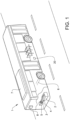
- FIG. 1 With initial reference to figure 1 , there is shown a simplified perspective view of a vehicle in the form of a bus 1.
- the bus 1 is of the so-called plug-in hybrid type and is equipped with an internal combustion engine 2 and an electric machine 3 which are connected to each other via a clutch 4. Both the internal combustion engine 2 and the electrical machine 3 can be used to drive the bus 1.
- the electric machine 3 is connected to a gearbox 5, which in turn is connected to a driven axle 6 of the bus 1, in this case the rear axle.
- both axles or either axle, or the front axle may be the driven axle.
- the internal combustion engine 2 and the electric machine 3 can be used for driving the axle 6.
- the electric machine 3 is used as a combined electric drive motor and generator, and is suitably also used as a starter motor for the internal combustion engine 2.
- the electric machine 3 may equally well be separate from a generator and/or starter motor for the internal combustion engine 2.
- the bus 1 carries an electric energy storage system 7 which comprises a battery pack 7a which in turn comprises a plurality of battery cells (not shown in detail in figure 1 ).
- the battery cells are connected in series to provide an output DC voltage having a desired voltage level.
- the battery cells are of lithium-ion type, but other types may in principle also be used.
- the energy storage system 7 also comprises a sensor unit 7b which is arranged for measuring one or more predetermined parameters which are indicative of the state of operation of the battery pack 7a.
- the sensor unit 7b may be configured for measuring the voltage of the battery pack 7a and each individual battery cell.
- the sensor unit 7b may be configured for measuring an alternative parameter, such as the battery current and the temperature of the battery pack 7a and each individual battery cell.
- the sensor unit 7b can be used for measuring further signals which are related to the status of the performance, in terms of its power, capacity or other suitable parameters, of the battery pack 7a and each individual battery cell.
- the parameter or parameters measured by means of the sensor unit 7b can be utilized in further processes.
- the energy storage system 7 is arranged on the roof of the bus 1.
- the energy storage system 7 may be arranged anywhere suitable in the vehicle.
- the energy storage system 7 may often be arranged in the lower portions of the vehicle 1 such that the center of mass is lower.
- the above-mentioned components of the propulsion system of the bus 1, including the energy storage system 7, are connected to a vehicle control unit 20.
- this disclosure refers to a battery pack 7a used in a vehicle 1 in the form of a bus, it can be applied in virtually any type of vehicle which has an energy storage system comprising a battery pack with a number of battery cells.
- the invention can be applied in hybrid electric vehicles (HEV), full electric vehicles (FEV), battery electric vehicles (BEV), plug-in hybrid vehicles (PHEV) and other forms of vehicles using batteries.
- HEV hybrid electric vehicles
- FEV full electric vehicles
- BEV battery electric vehicles
- PHEV plug-in hybrid vehicles
- the invention may be used in a truck or a construction equipment machine.
- the invention can also be used in marine vessels and applications involving power plants and other situations in which battery packs of the above-mentioned type are used.
- the bus 1 is equipped with a first electric connector element 9, for example in the form of a plug or pantograph.
- the first electric connector element 9 is arranged to be connected to a second electric connector element 10, for example in the form of an external electrical plug or an overhead electrical conductor wire, or any other form of an external electrical connector.
- the external connector 10 is connected to an external electrical power supply 11, and may thus charge the energy storage system 7 when connected.
- the present invention is also suitable to use in a HEV, FEV, and BEV where the vehicle may operate without contact with an external power supply 11 during operation.
- the bus 1 also comprises a vehicle control unit 20.
- the vehicle control unit 20 comprises electronic circuits and connections (not shown) as well as processing circuitry (not shown) such that the vehicle control unit 20 can communicate with different parts of the bus 1 such as the brakes, suspension, driveline, in particular the internal combustion engine 2, the electric machine 3, the clutch 4, and the gearbox 5 in order to operate the bus 1.
- the vehicle control unit 20 may comprise modules in either hardware or software, or partially in hardware or software and communicate using known transmission buses such as CAN-bus.
- the processing circuitry may be a general purpose processor or a specific processor.
- the vehicle control unit 20 comprises a non-transistory memory for storing computer program code and data upon. Thus, the skilled addressee realizes that the vehicle control unit 20 may be embodied by many different constructions.
- the vehicle control unit 20 is connected to the battery control unit 8 of the battery for transmitting and receiving information, such as power requests as a result of the driver of the vehicle 1 operating the vehicle 1.
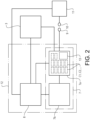
- FIG. 2 is a simplified schedule of the battery pack 7a and associated components of the vehicle 1.
- the battery pack 7a comprises a number of battery cells C1, C2, C3, ... etc. (also referred to with reference “C").
- C battery cells
- the number of battery cells is in the range of 90 to 400 cells, although the specific number may vary.
- the battery cells are of the lithium ion type, although the principles of the invention are equally applicable to other types of battery cells.
- the battery pack 7a is connected to the electric machine 3 and is configured for operating the electric machine 3 (which in turn operates the vehicle 1). Furthermore, the battery pack 7a is connected to the sensor unit 7b, which in turn is connected to a battery control unit 8.
- the sensor unit 7b may be configured for measuring the voltage, temperature or other parameters of the battery pack 7a. Consequently, the sensor unit 7b is configured for measuring the terminal voltage U for each battery cell C and for transmitting information related to the measured voltage values to the battery control unit 8. As mentioned above, the sensor unit 7b may be configured to measure further parameters, such as the current and the temperature each individual battery cell C1, C2, C3... etc. Also, the sensor unit 7b may be used for measuring further signals which are related to the status of the performance, in terms of its power, capacity or other suitable parameters, of each individual battery cell of the battery 7a.
- an arrangement for classifying a voltage fault condition of the battery pack 7a comprises the sensor unit 7b arranged to detect a cell voltage of one of the cells C and the battery control unit 8.
- the battery control unit 8 is configured to determine that a cell C, e.g. one of the cells has a voltage fault condition based on the cell voltage being outside a predetermined voltage range.
- a predetermined voltage range for the cell may be e.g. a voltage range of 1V to 10V.
- a predetermined voltage range for the cell may be e.g. a voltage range of 1.0V to 5.0V, or 2.7V to 3.4V, or 2.7V to 4.0V.
- a voltage outside such a range may be utilized to determine that a voltage fault condition is present.
- the voltage range may depend on the chemistry of the cell, and also the power window and energy window that is required. Both the power window and the energy window may influence the voltage range and thus the trigger conditions for a voltage fault condition. It should thus be understood that the present invention may be used to advantage with a wide range of batteries and battery cell chemistries.
- the battery control unit 8 is further configured to classify the severity of the voltage fault condition based on the cell voltage. Stated differently, the battery control unit 8 classifies the severity of the voltage fault condition based on the magnitude of the measured cell voltage.
- the control unit 8 is further configured to perform at least one diagnostic test routine to provide a cause for the voltage fault condition.
- the battery control unit 8 starts to perform diagnostic test routines for causes which are likely to correspond to the measured severity of the voltage fault condition, the battery control unit 8 is likely to find that cause or causes in a quicker manner that simply randomly testing causes for voltage fault conditions.
- the battery control unit 8 is further configured to select and adapt a battery operation condition, based on the severity of the voltage fault condition, such that the battery is enabled to continue to operate the vehicle.
- a diagnostic test routine should be in the context of this application be construed as a test to identify and verify the cause(s) and reason(s) which lead to the voltage fault condition. This will be further exemplified in the following in conjunction with figures 3 and 4 .
- the battery control unit 8 may communicate with the vehicle control unit 20.
- To classify the severity of the voltage fault condition may comprise classifying the voltage fault condition to be of low severity, medium severity, high severity or breakdown severity.
- a low severity should be understood to mean that selecting and adapting a battery operation condition comprises adapting the battery itself, whereas for the medium severity, high severity and breakdown severity comprise adapting control parameters for the vehicle via the vehicle control unit 20 in order to reduce the severity of the voltage fault condition.
- a certain cause leading to a voltage fault condition may be classified differently based on information relating to the vehicles previous action.
- the battery control unit 8 which measures and controls the power output from the battery 7.
- the vehicle control unit 20 may exceed this limit due to actions of e.g. the driver which causes the voltage to exceed the predetermined threshold.
- the exceeded power usage may be an isolated incident, and the corresponding voltage fault condition be classified at a lower severity based on data from the vehicle control unit 20.
- the data received from the vehicle control unit 20 indicates that the power usage has not been exceeded; the voltage fault condition severity is classified based on the cell voltage.
- the battery control unit 8 may be best understood in the following description in relation to a method elucidated by the flowchart figure 3 and the graph in figure 4 .
- the battery control unit 8 may comprise a general purpose processor, a non-transitory memory, and electronic circuits required for the battery control unit 8 to communicate with at least the sensor unit 7b, the battery pack 7a, and also electronic circuits to drive a processor and memory.
- the battery control unit 8 may comprise electronic circuits required for communication wired or wirelessly with an external database, such as a remote server and the vehicle control unit 20.
- portions of the functionality may be embodied by software modules stored on a non-transistory memory, or by hardware modules (not shown) comprised in the battery control unit 8.
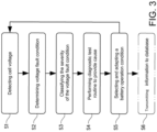
- Figure 3 is a flowchart which illustrates a method for classifying voltage fault condition in a battery according to at least one embodiment of the invention. The method may for example be carried out using the components and systems illustrated and described in conjunction with figure 1 and 2 .
- the method comprises a first step, S1, of detecting a cell voltage of one of the cells C.
- the cell voltage may be detected for example via the sensor unit 7b shown in figure 2 .
- the method comprises a further step, S2, of determining that the cell has a voltage fault condition based on the cell voltage being outside a predetermined voltage range.
- a predetermined voltage range for the cell may be e.g. a voltage range of 2.7 to 4.0 V.
- the control unit 8 may make the comparison between the measured cell voltage U and the predetermined voltage range.
- the method typically continues to measure another cell of the battery. It is of course also possible that the method is performed in parallel simultaneously for a portion of the cells of the battery or for all the cells of the battery.
- the method comprises a further step, S3, of classifying the severity of the voltage fault condition based on the cell voltage.
- the severity is dependent on the magnitude of the voltage fault condition.
- Step S3 may further comprises increasing the severity of the voltage fault condition based on historical data. For example, the severity may be increased if a voltage fault condition has occurred previously for the cell. This means that a less serious voltage fault condition may be classified as more severe if a voltage fault condition has occurred more than once. Thereby, more severe cause(s) and reason(s) behind the voltage fault condition may be identified even if the severity of the voltage fault condition is low.
- the expression historical data should be interpreted as data based on the previous performance of the battery and/or cells such as voltage fault conditions, or data based on previous performance of a battery and/or cells which are of similar make and/or type and installed in a similar vehicle. The data may be stored in a control unit, or may be retrieved using a wired or wireless network from a remote database.
- Step S3 may further comprises classifying the voltage fault condition to be of low severity, medium severity, high severity or breakdown severity.
- a low severity should be understood to mean that, later in the method, selecting and adapting a battery operation condition comprises adapting the battery itself, whereas for the medium severity, high severity and breakdown severity comprise adapting control parameters for the vehicle and vehicle control unit(s) in order to reduce the severity of the voltage fault condition.
- a certain cause leading to a voltage fault condition may be classified differently based on information relating to the vehicles previous action. Further, it is not always the battery control unit which measures and controls the power output from the battery. Hence, even if the battery control unit has sent information relating to a predetermined limit of power usage, the vehicle control unit may exceed this limit due to actions of e.g.
- An adapted control parameter can thus introduce a "hard" limit to the vehicle control unit which is not allowed to be exceeded.
- the exceeded power usage may be an isolated incident, and the corresponding voltage fault condition be classified at a lower severity based on data from the vehicle control unit(s).
- the voltage fault condition severity is classified based on the cell voltage. Exemplary ranges for the severity level(s) are exemplified in figure 4 .
- the method comprises a further step, S4, of performing at least one diagnostic test routine to provide a cause for the voltage fault condition.
- diagnostic test routines to detect specific cause(s) will be explained in the following. However, the skilled addressee realizes that the inventive concept encompasses also suitable tests not explicitly noted, and may in principle use any test which is capable of identifying and providing a cause for the voltage fault condition.
- the method comprises a further step, S5, of selecting and adapting a battery operation condition, based on the severity of the voltage fault condition and the cause, such that the battery is enabled to continue to operate the vehicle.
- Exemplary battery operation conditions will be exemplified in conjunction with figure 4 .
- the step S5 comprises at least one of the following: changing a parameter in a control algorithm, charging the cell, discharging the cell, balancing the electrical storage system, or performing a SOH calibration.
- Changing a parameter in a control algorithm may comprise adapting the maximum state-of-power (SOP) from the battery pack in the control unit, or adapting the state-of-charge (SOC) window such that a cell voltage fault condition is less likely to occur. Stated differently, the allowable high and low limit of SOC for the cell may be decreased such that the SOC window is moved or narrowed.
- selecting and adapting a battery operation may comprise adapting a temperature control parameter as disclosed in the International
- the battery control unit may transmit data regarding the power usage and setting to a vehicle control unit in order to limit the power withdrawal requirements from the vehicle control unit.
- the step S5 may further comprise transmitting adapted control parameter to the vehicle control unit.
- the control parameter may comprise information relating to at least one of: maximum allowable power withdrawal, maximum allowable energy withdrawal.
- the method may further comprise repeating the steps of the method, as indicated by the arrow from S5 to S1, for a portion of the cells of a battery, or for all the cells of the battery. Stated differently, the method is repeatedly performed for a portion of the cells of the battery, or for all the cells of the battery in order to classify the voltage fault condition of the whole battery.
- the method may optionally further comprise a step S6 of transmitting the detected cell voltage, the at least one diagnostic test, the severity, the cause and the battery operation selected or adapted.
- the detected cell voltage, the at least one diagnostic test, the severity, the cause and the battery operation selected or adapted may be sent to a remote database via a wired or wireless connection such that the historical data of the cause and other parameter may be provided to other arrangements and/or vehicles utilizing the inventive concept.
- Figure 4 is a graph showing the normal operating regions of the cell voltage as well as regions outside the normal operating range.
- the areas outside the normal operating region are examples of voltage fault conditions.
- the text under "Perform test and adapt" is only noted on the voltage levels above the predetermined voltage range and not on the levels below the predetermined voltage range, the same of course applies to these levels as the levels of corresponding severity.
- the predetermined voltage range may be 2.7V to 3.4V, but may also differ for different types of batteries and applications etc.
- regions of voltage fault conditions are shown. The regions of voltage fault conditions closer to the normal operating range are regions of lower severity, with regard to the magnitude of the voltage fault condition without taking the cause into account.
- a voltage fault condition being detected in the exemplary ranges of 2.5V to 2.7V or 3.4V to 3.6V will be deemed to be off low severity.
- a voltage fault condition being detected in the exemplary ranges of 2.2V to 2.5V or 3.6V to 3.8V will be deemed to be off medium severity.
- a voltage fault condition being detected in the exemplary ranges of 2.0V to 2.2V or 3.8V to 4.0V will be deemed to be off high severity.
- a voltage fault condition outside those exemplary boundaries would cause a cell failure to be classified directly and the cell to be disconnected from the rest of the battery if possible, otherwise the control unit may cause the available power from the battery to be reduced to low level but still sufficient for the vehicle in which the invention is installed to safely stop or reach a service station. Alternatively, such a high voltage fault condition may trigger a direct shut-down of the battery for safety reasons.
- the arrow A1 represents time during the operation of the method. Firstly, a detection of the cell voltage and a possible voltage fault condition is performed, for example according to the regions shown in figure 4 , thereafter the voltage fault condition is classified, upon which the most likely cause will be investigated using at least one diagnostic test routine. When the cause(s) is/are found a battery operation condition is selected and adapted such that the battery is enabled to continue to operate the vehicle.
- the diagnostic test routine may comprise determining whether the cell is unbalanced compared to the rest of the cells of the battery.
- the determination that the cell is unbalanced with regard to the rest of the cells of the battery may be based on the voltage level at which the balancing determination was made, or the time since last balancing period, or the degree of completion of the last balancing period, and the amount of current through cell the since last balancing period.
- the determination that the cell is unbalanced with regard to the rest of the cells of the battery may not simply comprising determining a state-of-balance, SOB, but also other factors involved in balancing.
- the diagnostic test routine may comprise determining whether the state of charge, SOC, of the cell is inaccurate.
- the determination that the SOC of the cell is inaccurate may be based on based on the voltage level at which the previous SOC determination from open circuit voltage (OCV) was made, temperature at which the previous SOC determination from OCV was made, amount of current through cell since the last OCV determination, and an inaccuracy of a current sensor.
- OCV open circuit voltage
- an inaccurate SOC may also be detected and determined based on the voltage of the cell reaching either a high or low voltage under load.
- a high or low voltage should hereby be understood as a voltage outside a predetermined voltage range for the cell.
- a low severity cause may be an inaccurate SOH of the cell.
- the diagnostic test routine may comprise determining whether the state-of-health, SOH, of the cell is inaccurate. Hence, if none of the other diagnostic test routines returned a cause for voltage fault condition the SOH of the cell is deemed inaccurate and is therefore lowered to take into account the lower SOH for future use of the cell. Additionally, determining the SOH of the cell is inaccurate may comprise performing the method for a plurality of cells, such as 5, 10, 15, 20 or more cell, and determining that the SOH is inaccurate based on the result of no cause being determined for a voltage fault condition for the plurality of cells.
- the power usage and settings for ageing may be adapted.
- Power usage and settings for ageing should be interpreted as limiting the power able to be withdrawn from the cell, and reducing the available total capacity from the cell in a battery control unit.
- the battery control unit may transmit data regarding the power usage and setting to a vehicle control unit in order to limit the power withdrawal requirements from the vehicle control unit.
- a medium severity cause may be an abnormal temperature of the cell.
- the diagnostic test routine may comprise measuring the cell temperature and determining whether the cell temperature is outside a predetermined cell temperature working range.
- the predetermined cell temperature range may be -30 to 90 degrees centigrade, or -10 to 60 degrees centigrade. Further, this may of course indicated a malfunction in a heating/cooling system for the battery. Selecting and adapting a battery operation condition may thus comprise heating or cooling the cell. By bringing the cell temperature into the predetermined cell temperature working range by operating a cooling or heating device, the cause of voltage fault condition is counteracted.
- a medium severity cause may be current or power overshoot.
- the diagnostic test routine may comprise determining whether a current or power withdrawn or applied from or to the cell exceeds a predetermined current or power threshold. The determination may be made for momentaneous withdrawal of current or power, or over a predetermined period of time such as a driving cycle, hours, minutes, or seconds. Stated differently, by determining whether current or power withdrawn from the cell exceeds a predetermined amount instantaneously or over a period of time the cause for the voltage fault condition is determined as current or power overshoot. Hence, a power pulse provided from the battery to the vehicle which exceeds the predetermined parameters is detrimental to the battery.
- a medium severity cause may be disturbances on the traction voltage.
- the diagnostic test routine may comprise determining whether disturbances on the traction voltage are present. Disturbances on the traction voltage may be from a component with intermittent isolation problems (to ground), or intermittent short circuit pole-pole causing EMC behavior outside the specified traction voltage. Alternatively, components may be going on/off and causing the behavior on the traction voltage not to be according to expectation.
- a breakdown severity cause may be a cell failure.
- the diagnostic test routine comprises determining whether the cell has failed. The determination whether the cell has failed may be based on the cell reaching both a cell voltage above and below the predetermined voltage range under load, or that the cell reaches has the lowest voltage under load also has the lowest voltage under no load, or that the cell having the highest voltage under load also has the highest voltage under no load. Alternatively, the determination whether the cell has failed may be based whether a cell has a resistance higher than a failure threshold, or whether the capacity of the cell differentiates from the rest of the cells of the battery. A threshold difference in capacity between the cell and the rest of the cell of the battery may be a capacity which is 10% lower than a mean or median value of the capacity of the cells of the battery. The failure threshold of resistance will be floating over life and it will be relative to what it should be at the given time and the actual threshold is in voltage, 2.2 and 4.0V, at a power (current) that should have been possible at that age based on historical or known data.
- low severity causes of a voltage fault condition may be:
- Medium severity causes of a voltage fault condition may be:
- High severity causes of a voltage fault condition may be:
- Breakdown severity causes of a voltage fault condition may be:
- the next step is to search a lower severity level for the cause, as indicated by the arrow A2. Further, the method may also search for additional causes to the voltage fault conditions so that several cause(s) are found if applicable.
- causes and/or severity levels may in an alternative embodiment rather be seen as a probability function centered and/or continuous functions around labels.
- probability functions and/or continuous functions for the causes and severity levels may be updated and adapted.
- the present disclosure contemplates methods, systems and program products on any machine-readable media for accomplishing various operations.
- the embodiments of the present disclosure may be implemented using existing computer processors, or by a special purpose computer processor for an appropriate system, incorporated for this or another purpose, or by a hardwired system.
- Embodiments within the scope of the present disclosure include program products comprising machine-readable media for carrying or having machine-executable instructions or data structures stored thereon.
- Such machine-readable media can be any available media that can be accessed by a general purpose or special purpose computer or other machine with a processor.
- machine-readable media can comprise RAM, ROM, EPROM, EEPROM, CD-ROM or other optical disk storage, magnetic disk storage or other magnetic storage devices, or any other medium which can be used to carry or store desired program code in the form of machine-executable instructions or data structures and which can be accessed by a general purpose or special purpose computer or other machine with a processor.
- a network or another communications connection either hardwired, wireless, or a combination of hardwired or wireless
- any such connection is properly termed a machine-readable medium.
- Machine-executable instructions include, for example, instructions and data which cause a general purpose computer, special purpose computer, or special purpose processing machines to perform a certain function or group of functions.
Landscapes
- Engineering & Computer Science (AREA)
- General Physics & Mathematics (AREA)
- Physics & Mathematics (AREA)
- Electrochemistry (AREA)
- Chemical Kinetics & Catalysis (AREA)
- General Chemical & Material Sciences (AREA)
- Chemical & Material Sciences (AREA)
- Manufacturing & Machinery (AREA)
- Life Sciences & Earth Sciences (AREA)
- Sustainable Development (AREA)
- Sustainable Energy (AREA)
- Power Engineering (AREA)
- Transportation (AREA)
- Mechanical Engineering (AREA)
- Secondary Cells (AREA)
- Electric Propulsion And Braking For Vehicles (AREA)
Claims (14)
- Verfahren zum Klassifizieren eines Spannungsfehlerzustands einer Batterie (7) für ein Fahrzeug, die Batterie (7) umfassend eine Vielzahl von Zellen, wobei das Verfahren umfasst:- Erfassen einer Zellspannung von einer der Zellen;- Bestimmen, ob die Zelle einen Spannungsfehlerzustand aufweist, basierend darauf, dass die Zellspannung außerhalb eines vorbestimmten Spannungsbereichs ist;- Klassifizieren einer Schwere des Spannungsfehlerzustands, basierend auf der Zellspannung;- Durchführen mindestens einer diagnostischen Prüfroutine, basierend auf der Schwere des Spannungsfehlerzustands, um eine Ursache für den Spannungsfehlerzustand bereitzustellen;- Auswählen und Anpassen eines Betriebszustands der Batterie (7), basierend auf der Schwere des Spannungsfehlerzustands und der Ursache, derart, dass die Batterie (7) betriebsbereit ist, um das Fahrzeug weiterhin zu betreiben, dadurch gekennzeichnet, dass
der Schritt des Klassifizierens der Schwere des Spannungsfehlerzustands ferner das Klassifizieren des Spannungsfehlerzustands als mit niedriger Schwere, mittlerer Schwere, hoher Schwere oder Ausfallschwere umfasst, und dass das Verfahren ferner ein Erhöhen der Schwere des Spannungsfehlerzustands umfasst, falls ein Spannungsfehlerzustand für die Zelle zuvor aufgetreten ist. - Verfahren nach Anspruch 1, wobei das Verfahren ferner ein Übertragen angepasster Steuerparameter an die Fahrzeugsteuereinheit (8) umfasst, die Steuerparameter umfassend Informationen, die sich auf mindestens eines beziehen von: maximal zulässiger Leistungsentnahme und maximal zulässiger Energieentnahme.
- Verfahren nach einem der Ansprüche 1 oder 2, wobei die mindestens eine diagnostische Prüfroutine das Messen der Zelltemperatur und das Bestimmen, ob die Zelltemperatur außerhalb eines vorbestimmten Temperaturarbeitsbereichs liegt, umfasst.
- Verfahren nach Anspruch 3, wobei das Auswählen und Anpassen eines Betriebszustands einer Batterie (7) ein Erwärmen oder Kühlen der Zelle umfasst.
- Verfahren nach einem der vorstehenden Ansprüche, wobei die mindestens eine diagnostische Prüfroutine das Bestimmen, ob ein Strom oder eine Leistung, die von der Zelle entnommen werden oder an diese angelegt werden, einen vorbestimmten Strom- oder Leistungsschwellenwert über einen Zeitraum überschreiten, umfasst.
- Verfahren nach einem der vorstehenden Ansprüche, wobei die mindestens eine diagnostische Prüfroutine das Bestimmen, ob die Zelle im Vergleich zu den restlichen Zellen der Batterie (7) unausgeglichen ist, umfasst.
- Verfahren nach einem der vorstehenden Ansprüche, wobei die mindestens eine diagnostische Prüfroutine das Bestimmen, ob der Ladezustand, SOC, der Zelle ungenau ist, umfasst.
- Verfahren nach einem der vorstehenden Ansprüche, wobei die mindestens eine diagnostische Prüfroutine das Bestimmen, ob die Zelle ausgefallen ist, umfasst.
- Verfahren nach Anspruch 8, wobei die mindestens eine diagnostische Prüfroutine das Bestimmen des Gesundheitszustands, SOH, der Zelle umfasst.
- Verfahren nach einem der vorstehenden Ansprüche, wobei das Auswählen und Anpassen eines Betriebs einer Batterie (7) mindestens eines der Folgenden umfasst: Ändern eines Parameters in einem Steueralgorithmus, Laden der Zelle, Entladen der Zelle, Ausgleichen des elektrischen Speichersystems.
- Verfahren nach einem der vorstehenden Ansprüche, wobei das Verfahren ferner den Schritt des Übertragens der erfassten Zellspannung, der mindestens einen diagnostischen Prüfung, der Schwere, der Ursache und des Betriebs der Batterie (7), der ausgewählt oder angepasst ist, umfasst.
- Computerprogrammprodukt, umfassend Computerprogrammcode, der, wenn er durch einen Prozessor ausgeführt wird, die Anordnung nach Anspruch 13 veranlasst, die Schritte des Verfahrens nach einem der Ansprüche 1 bis 11 durchzuführen.
- Anordnung zum Klassifizieren eines Spannungsfehlerzustands einer Batterie (7), umfassend eine Vielzahl von Zellen für ein Fahrzeug, wobei die Anordnung umfasst:- einen Sensor, der angeordnet ist, um eine Zellspannung von mindestens einer der Zellen zu erfassen; und- eine Steuereinheit (8), die konfiguriert ist, um zu bestimmen, dass die Zelle einen Spannungsfehlerzustand aufweist, basierend darauf, dass die Zellspannung außerhalb eines vorbestimmten Spannungsbereichs liegt, und um die Schwere des Spannungsfehlerzustands, basierend auf der Zellspannung zu klassifizieren;- die Steuereinheit (8) ferner konfiguriert ist, um mindestens eine diagnostische Prüfroutine durchzuführen, um eine Ursache für den Spannungsfehlerzustand bereitzustellen und einen Betriebszustand der Batterie (7), basierend auf der Schwere des Spannungsfehlerzustands und der Ursache anzupassen, derart, dass die Batterie (7) betriebsbereit ist, um das Fahrzeug weiterhin zu betreiben, dadurch gekennzeichnet, dassdie Steuereinheit (8) konfiguriert ist, um die Schwere des Spannungsfehlerzustands als mit niedriger Schwere, mittlerer Schwere, hoher Schwere oder Ausfallschwere zu klassifizieren, unddie Steuereinheit (8) konfiguriert ist, um die Schwere des Spannungsfehlerzustands zu erhöhen, falls ein Spannungsfehlerzustand für die Zelle zuvor aufgetreten ist.
- Fahrzeug, umfassend die Anordnung nach Anspruch 13.
Priority Applications (1)
| Application Number | Priority Date | Filing Date | Title |
|---|---|---|---|
| EP24168939.7A EP4398378A3 (de) | 2016-11-25 | 2016-11-25 | Verfahren und anordnung zur klassifizierung eines spannungsfehlerzustands in einem elektrischen speichersystem |
Applications Claiming Priority (1)
| Application Number | Priority Date | Filing Date | Title |
|---|---|---|---|
| PCT/EP2016/078811 WO2018095534A1 (en) | 2016-11-25 | 2016-11-25 | Method and arrangment for classifying a voltage fault condition in an electrical storage system |
Related Child Applications (1)
| Application Number | Title | Priority Date | Filing Date |
|---|---|---|---|
| EP24168939.7A Division EP4398378A3 (de) | 2016-11-25 | 2016-11-25 | Verfahren und anordnung zur klassifizierung eines spannungsfehlerzustands in einem elektrischen speichersystem |
Publications (3)
| Publication Number | Publication Date |
|---|---|
| EP3545320A1 EP3545320A1 (de) | 2019-10-02 |
| EP3545320C0 EP3545320C0 (de) | 2024-05-01 |
| EP3545320B1 true EP3545320B1 (de) | 2024-05-01 |
Family
ID=57396442
Family Applications (2)
| Application Number | Title | Priority Date | Filing Date |
|---|---|---|---|
| EP16801471.0A Active EP3545320B1 (de) | 2016-11-25 | 2016-11-25 | Verfahren und anordnung zur klassifizierung eines spannungsfehlerzustands in einem elektrischen speichersystem |
| EP24168939.7A Pending EP4398378A3 (de) | 2016-11-25 | 2016-11-25 | Verfahren und anordnung zur klassifizierung eines spannungsfehlerzustands in einem elektrischen speichersystem |
Family Applications After (1)
| Application Number | Title | Priority Date | Filing Date |
|---|---|---|---|
| EP24168939.7A Pending EP4398378A3 (de) | 2016-11-25 | 2016-11-25 | Verfahren und anordnung zur klassifizierung eines spannungsfehlerzustands in einem elektrischen speichersystem |
Country Status (4)
| Country | Link |
|---|---|
| US (1) | US11175341B2 (de) |
| EP (2) | EP3545320B1 (de) |
| CN (1) | CN109964138B (de) |
| WO (1) | WO2018095534A1 (de) |
Families Citing this family (9)
| Publication number | Priority date | Publication date | Assignee | Title |
|---|---|---|---|---|
| EP3751299B1 (de) * | 2019-06-11 | 2023-08-09 | Volvo Car Corporation | Detektion latenter fehler in einer zelle eines energiespeichersystems |
| DE102019135313A1 (de) * | 2019-12-19 | 2021-06-24 | Bayerische Motoren Werke Aktiengesellschaft | Verfahren zum Betrieb einer Batterie |
| CN111900498B (zh) * | 2020-06-30 | 2022-10-21 | 成都四威功率电子科技有限公司 | 一种电池管理系统故障信息的存储与检索方法 |
| CN114148218B (zh) * | 2020-09-07 | 2023-09-08 | 北汽福田汽车股份有限公司 | 更新电池系统sop参数值的方法、装置以及一种电动汽车 |
| CN112208389B (zh) * | 2020-09-08 | 2022-02-11 | 北京交通大学 | 一种针对车载动力电池的日常便捷检测方法 |
| CN112394291B (zh) * | 2020-11-05 | 2024-06-11 | 广汽埃安新能源汽车有限公司 | 一种电池热失控预警方法及装置 |
| CN112505550B (zh) * | 2020-11-26 | 2022-06-07 | 重庆长安汽车股份有限公司 | 一种动力电池监控预警方法 |
| EP4425199B1 (de) * | 2022-01-07 | 2025-11-12 | LG Energy Solution, Ltd. | Batteriedatenverwaltungsvorrichtung und betriebsverfahren |
| DE102024202369A1 (de) | 2024-03-13 | 2025-09-18 | Robert Bosch Gesellschaft mit beschränkter Haftung | Verfahren zum Ermitteln eines prädizierten Alterungszustands eines elektrochemischen Energiespeichers |
Family Cites Families (24)
| Publication number | Priority date | Publication date | Assignee | Title |
|---|---|---|---|---|
| US5804894A (en) * | 1996-08-16 | 1998-09-08 | Telxon Corporation | Low voltage battery pack monitoring circuit with adjustable set points |
| JP4353050B2 (ja) * | 2004-09-30 | 2009-10-28 | ソニー株式会社 | バッテリーパック |
| WO2010042517A1 (en) | 2008-10-07 | 2010-04-15 | Boston-Power, Inc. | Li-ion battery array for vehicle and other large capacity applications |
| US8330420B2 (en) * | 2009-04-10 | 2012-12-11 | The Regents Of The University Of Michigan | Dynamically reconfigurable framework for a large-scale battery system |
| WO2011037257A1 (ja) * | 2009-09-28 | 2011-03-31 | 日立ビークルエナジー株式会社 | 電池システム |
| US8384354B2 (en) * | 2009-10-15 | 2013-02-26 | GM Global Technology Operations LLC | Sensor arrangement and method of using the same |
| JP2011130551A (ja) * | 2009-12-16 | 2011-06-30 | Sanyo Electric Co Ltd | 電源装置及びこれを備える車両 |
| CN201673232U (zh) * | 2010-05-17 | 2010-12-15 | 乌景杰 | 一种高压输电线路智能监测终端 |
| KR101293635B1 (ko) * | 2010-12-29 | 2013-08-05 | 주식회사 엘지화학 | 이차전지 셀의 퇴화 정도를 반영한 배터리 팩의 관리 장치와 방법 및 이를 구비한 배터리 팩 |
| US9746525B2 (en) * | 2011-09-08 | 2017-08-29 | Hitachi Automotive Systems, Ltd. | Battery system monitoring device |
| US20130127611A1 (en) | 2011-11-20 | 2013-05-23 | Battery Marvel, Llc. | Battery marvel 1.0 |
| CN104272126B (zh) | 2012-04-27 | 2017-09-05 | 日立汽车系统株式会社 | 电池监视装置和电池系统监视装置 |
| US9519027B2 (en) | 2012-04-27 | 2016-12-13 | Hitachi Automotive Systems, Ltd. | Battery monitoring device and battery system monitoring device |
| CN103064032A (zh) | 2013-01-08 | 2013-04-24 | 重庆长安汽车股份有限公司 | 一种动力电池的故障诊断系统 |
| JP6247460B2 (ja) | 2013-06-14 | 2017-12-13 | 日立オートモティブシステムズ株式会社 | 電池制御装置 |
| CN103312009B (zh) | 2013-07-05 | 2015-04-29 | 中国南方电网有限责任公司调峰调频发电公司 | 一种用于电网储能电站的电池模块管理方法 |
| GB2528290A (en) | 2014-07-16 | 2016-01-20 | John Leslie Gordon Hardy | Battery management |
| CN104833926A (zh) * | 2015-05-07 | 2015-08-12 | 昆山弗尔赛能源有限公司 | 燃料电池备用电源系统的监测方法及系统 |
| CN107614313A (zh) | 2015-06-10 | 2018-01-19 | 沃尔沃卡车集团 | 用于优化能量存储系统的寿命的方法和系统 |
| WO2017024105A1 (en) * | 2015-08-06 | 2017-02-09 | The Regents Of The University Of Michigan | Fault tolerant voltage measurement method |
| CN105514526B (zh) * | 2015-12-02 | 2019-02-26 | 北京新能源汽车股份有限公司 | 电池模组的加热控制系统和方法 |
| CN105691226B (zh) | 2016-01-21 | 2018-09-21 | 中国第一汽车股份有限公司 | 一种锂离子动力电池系统的故障处理系统的处理方法 |
| CN105955160B (zh) * | 2016-05-13 | 2019-07-26 | 中车株洲电力机车研究所有限公司 | 一种变频器控制系统信号监控方法、装置及系统 |
| CN105857109B (zh) * | 2016-06-03 | 2018-03-16 | 河北工业大学 | 一种基于单片机的电动汽车电源管理系统 |
-
2016
- 2016-11-25 EP EP16801471.0A patent/EP3545320B1/de active Active
- 2016-11-25 WO PCT/EP2016/078811 patent/WO2018095534A1/en not_active Ceased
- 2016-11-25 CN CN201680090908.3A patent/CN109964138B/zh active Active
- 2016-11-25 EP EP24168939.7A patent/EP4398378A3/de active Pending
- 2016-11-25 US US16/461,195 patent/US11175341B2/en active Active
Also Published As
| Publication number | Publication date |
|---|---|
| EP4398378A3 (de) | 2024-09-18 |
| US20190310319A1 (en) | 2019-10-10 |
| EP3545320C0 (de) | 2024-05-01 |
| US11175341B2 (en) | 2021-11-16 |
| WO2018095534A1 (en) | 2018-05-31 |
| EP4398378A2 (de) | 2024-07-10 |
| CN109964138A (zh) | 2019-07-02 |
| CN109964138B (zh) | 2022-06-21 |
| EP3545320A1 (de) | 2019-10-02 |
Similar Documents
| Publication | Publication Date | Title |
|---|---|---|
| EP3545320B1 (de) | Verfahren und anordnung zur klassifizierung eines spannungsfehlerzustands in einem elektrischen speichersystem | |
| US9350187B2 (en) | Pre-charging vehicle bus using parallel battery packs | |
| US9059486B2 (en) | Automatic crash battery discharge method | |
| US9153990B2 (en) | Steady state detection of an exceptional charge event in a series connected battery element | |
| CN105301425B (zh) | 线束异常检测系统和方法 | |
| US10355498B2 (en) | Response to detection of an overdischarge event in a series connected battery element | |
| KR102253844B1 (ko) | 전기자동차 충전 시스템 | |
| EP3149499B1 (de) | Verfahren und system zur überwachung des status von batteriezellen | |
| CN112526379A (zh) | 用于监测电池组中的多个电池单体的状态的方法 | |
| US9529048B2 (en) | Transient detection of an exceptional charge event in a series connected battery element | |
| EP3468830B1 (de) | Verfahren und vorrichtung zur steuerung des betriebs eines stromspeichersystems in einem fahrzeug | |
| JP2013540415A (ja) | 低電圧領域と高電圧領域を有する電流供給システムのためのバッテリー管理システム | |
| US20140152259A1 (en) | Response to detection of an overcharge event in a series connected battery element | |
| CN112512855A (zh) | 用于混合动力或电动车辆的驱动能量蓄存器的系统和用于给混合动力或电动车辆的驱动能量蓄存器充电的方法 | |
| CN114103665B (zh) | 电能存储系统中的电池模块和子包的关联的确定 | |
| CN105452890A (zh) | 用于诊断蓄电池的状态的方法 | |
| WO2015022731A1 (ja) | 電池監視装置、電池システムおよび車両制御システム | |
| KR101866050B1 (ko) | 배터리셀 전압 편차 검출장치 및 그 방법 | |
| KR20160050918A (ko) | 배터리 보호 기능을 갖는 전기 차량용 배터리 충전 장치 | |
| KR20250050189A (ko) | 친환경차 배터리 셀의 용접 상태를 진단하는 방법 및 장치 | |
| KR20250110410A (ko) | 친환경차 배터리 전압 감지를 검증하는 방법 및 시스템 |
Legal Events
| Date | Code | Title | Description |
|---|---|---|---|
| STAA | Information on the status of an ep patent application or granted ep patent |
Free format text: STATUS: UNKNOWN |
|
| STAA | Information on the status of an ep patent application or granted ep patent |
Free format text: STATUS: THE INTERNATIONAL PUBLICATION HAS BEEN MADE |
|
| PUAI | Public reference made under article 153(3) epc to a published international application that has entered the european phase |
Free format text: ORIGINAL CODE: 0009012 |
|
| STAA | Information on the status of an ep patent application or granted ep patent |
Free format text: STATUS: REQUEST FOR EXAMINATION WAS MADE |
|
| 17P | Request for examination filed |
Effective date: 20190612 |
|
| AK | Designated contracting states |
Kind code of ref document: A1 Designated state(s): AL AT BE BG CH CY CZ DE DK EE ES FI FR GB GR HR HU IE IS IT LI LT LU LV MC MK MT NL NO PL PT RO RS SE SI SK SM TR |
|
| AX | Request for extension of the european patent |
Extension state: BA ME |
|
| DAV | Request for validation of the european patent (deleted) | ||
| DAX | Request for extension of the european patent (deleted) | ||
| STAA | Information on the status of an ep patent application or granted ep patent |
Free format text: STATUS: EXAMINATION IS IN PROGRESS |
|
| 17Q | First examination report despatched |
Effective date: 20220829 |
|
| GRAP | Despatch of communication of intention to grant a patent |
Free format text: ORIGINAL CODE: EPIDOSNIGR1 |
|
| STAA | Information on the status of an ep patent application or granted ep patent |
Free format text: STATUS: GRANT OF PATENT IS INTENDED |
|
| INTG | Intention to grant announced |
Effective date: 20231123 |
|
| RIC1 | Information provided on ipc code assigned before grant |
Ipc: H01M 10/42 20060101ALI20231110BHEP Ipc: H01M 10/48 20060101ALI20231110BHEP Ipc: G01R 31/36 20190101AFI20231110BHEP |
|
| GRAS | Grant fee paid |
Free format text: ORIGINAL CODE: EPIDOSNIGR3 |
|
| GRAA | (expected) grant |
Free format text: ORIGINAL CODE: 0009210 |
|
| STAA | Information on the status of an ep patent application or granted ep patent |
Free format text: STATUS: THE PATENT HAS BEEN GRANTED |
|
| AK | Designated contracting states |
Kind code of ref document: B1 Designated state(s): AL AT BE BG CH CY CZ DE DK EE ES FI FR GB GR HR HU IE IS IT LI LT LU LV MC MK MT NL NO PL PT RO RS SE SI SK SM TR |
|
| REG | Reference to a national code |
Ref country code: GB Ref legal event code: FG4D |
|
| REG | Reference to a national code |
Ref country code: CH Ref legal event code: EP |
|
| REG | Reference to a national code |
Ref country code: IE Ref legal event code: FG4D |
|
| REG | Reference to a national code |
Ref country code: DE Ref legal event code: R096 Ref document number: 602016087310 Country of ref document: DE |
|
| U01 | Request for unitary effect filed |
Effective date: 20240528 |
|
| U07 | Unitary effect registered |
Designated state(s): AT BE BG DE DK EE FI FR IT LT LU LV MT NL PT SE SI Effective date: 20240606 |
|
| PG25 | Lapsed in a contracting state [announced via postgrant information from national office to epo] |
Ref country code: IS Free format text: LAPSE BECAUSE OF FAILURE TO SUBMIT A TRANSLATION OF THE DESCRIPTION OR TO PAY THE FEE WITHIN THE PRESCRIBED TIME-LIMIT Effective date: 20240901 |
|
| PG25 | Lapsed in a contracting state [announced via postgrant information from national office to epo] |
Ref country code: HR Free format text: LAPSE BECAUSE OF FAILURE TO SUBMIT A TRANSLATION OF THE DESCRIPTION OR TO PAY THE FEE WITHIN THE PRESCRIBED TIME-LIMIT Effective date: 20240501 |
|
| PG25 | Lapsed in a contracting state [announced via postgrant information from national office to epo] |
Ref country code: GR Free format text: LAPSE BECAUSE OF FAILURE TO SUBMIT A TRANSLATION OF THE DESCRIPTION OR TO PAY THE FEE WITHIN THE PRESCRIBED TIME-LIMIT Effective date: 20240802 |
|
| PG25 | Lapsed in a contracting state [announced via postgrant information from national office to epo] |
Ref country code: ES Free format text: LAPSE BECAUSE OF FAILURE TO SUBMIT A TRANSLATION OF THE DESCRIPTION OR TO PAY THE FEE WITHIN THE PRESCRIBED TIME-LIMIT Effective date: 20240501 |
|
| PG25 | Lapsed in a contracting state [announced via postgrant information from national office to epo] |
Ref country code: PL Free format text: LAPSE BECAUSE OF FAILURE TO SUBMIT A TRANSLATION OF THE DESCRIPTION OR TO PAY THE FEE WITHIN THE PRESCRIBED TIME-LIMIT Effective date: 20240501 |
|
| PG25 | Lapsed in a contracting state [announced via postgrant information from national office to epo] |
Ref country code: PL Free format text: LAPSE BECAUSE OF FAILURE TO SUBMIT A TRANSLATION OF THE DESCRIPTION OR TO PAY THE FEE WITHIN THE PRESCRIBED TIME-LIMIT Effective date: 20240501 Ref country code: NO Free format text: LAPSE BECAUSE OF FAILURE TO SUBMIT A TRANSLATION OF THE DESCRIPTION OR TO PAY THE FEE WITHIN THE PRESCRIBED TIME-LIMIT Effective date: 20240801 Ref country code: IS Free format text: LAPSE BECAUSE OF FAILURE TO SUBMIT A TRANSLATION OF THE DESCRIPTION OR TO PAY THE FEE WITHIN THE PRESCRIBED TIME-LIMIT Effective date: 20240901 Ref country code: HR Free format text: LAPSE BECAUSE OF FAILURE TO SUBMIT A TRANSLATION OF THE DESCRIPTION OR TO PAY THE FEE WITHIN THE PRESCRIBED TIME-LIMIT Effective date: 20240501 Ref country code: GR Free format text: LAPSE BECAUSE OF FAILURE TO SUBMIT A TRANSLATION OF THE DESCRIPTION OR TO PAY THE FEE WITHIN THE PRESCRIBED TIME-LIMIT Effective date: 20240802 Ref country code: ES Free format text: LAPSE BECAUSE OF FAILURE TO SUBMIT A TRANSLATION OF THE DESCRIPTION OR TO PAY THE FEE WITHIN THE PRESCRIBED TIME-LIMIT Effective date: 20240501 Ref country code: RS Free format text: LAPSE BECAUSE OF FAILURE TO SUBMIT A TRANSLATION OF THE DESCRIPTION OR TO PAY THE FEE WITHIN THE PRESCRIBED TIME-LIMIT Effective date: 20240801 |
|
| U20 | Renewal fee for the european patent with unitary effect paid |
Year of fee payment: 9 Effective date: 20241127 |
|
| PG25 | Lapsed in a contracting state [announced via postgrant information from national office to epo] |
Ref country code: CZ Free format text: LAPSE BECAUSE OF FAILURE TO SUBMIT A TRANSLATION OF THE DESCRIPTION OR TO PAY THE FEE WITHIN THE PRESCRIBED TIME-LIMIT Effective date: 20240501 |
|
| PG25 | Lapsed in a contracting state [announced via postgrant information from national office to epo] |
Ref country code: SK Free format text: LAPSE BECAUSE OF FAILURE TO SUBMIT A TRANSLATION OF THE DESCRIPTION OR TO PAY THE FEE WITHIN THE PRESCRIBED TIME-LIMIT Effective date: 20240501 Ref country code: RO Free format text: LAPSE BECAUSE OF FAILURE TO SUBMIT A TRANSLATION OF THE DESCRIPTION OR TO PAY THE FEE WITHIN THE PRESCRIBED TIME-LIMIT Effective date: 20240501 |
|
| PG25 | Lapsed in a contracting state [announced via postgrant information from national office to epo] |
Ref country code: SM Free format text: LAPSE BECAUSE OF FAILURE TO SUBMIT A TRANSLATION OF THE DESCRIPTION OR TO PAY THE FEE WITHIN THE PRESCRIBED TIME-LIMIT Effective date: 20240501 |
|
| PG25 | Lapsed in a contracting state [announced via postgrant information from national office to epo] |
Ref country code: SM Free format text: LAPSE BECAUSE OF FAILURE TO SUBMIT A TRANSLATION OF THE DESCRIPTION OR TO PAY THE FEE WITHIN THE PRESCRIBED TIME-LIMIT Effective date: 20240501 Ref country code: SK Free format text: LAPSE BECAUSE OF FAILURE TO SUBMIT A TRANSLATION OF THE DESCRIPTION OR TO PAY THE FEE WITHIN THE PRESCRIBED TIME-LIMIT Effective date: 20240501 Ref country code: RO Free format text: LAPSE BECAUSE OF FAILURE TO SUBMIT A TRANSLATION OF THE DESCRIPTION OR TO PAY THE FEE WITHIN THE PRESCRIBED TIME-LIMIT Effective date: 20240501 Ref country code: CZ Free format text: LAPSE BECAUSE OF FAILURE TO SUBMIT A TRANSLATION OF THE DESCRIPTION OR TO PAY THE FEE WITHIN THE PRESCRIBED TIME-LIMIT Effective date: 20240501 |
|
| REG | Reference to a national code |
Ref country code: DE Ref legal event code: R097 Ref document number: 602016087310 Country of ref document: DE |
|
| PLBE | No opposition filed within time limit |
Free format text: ORIGINAL CODE: 0009261 |
|
| STAA | Information on the status of an ep patent application or granted ep patent |
Free format text: STATUS: NO OPPOSITION FILED WITHIN TIME LIMIT |
|
| 26N | No opposition filed |
Effective date: 20250204 |
|
| REG | Reference to a national code |
Ref country code: CH Ref legal event code: PL |
|
| PG25 | Lapsed in a contracting state [announced via postgrant information from national office to epo] |
Ref country code: MC Free format text: LAPSE BECAUSE OF FAILURE TO SUBMIT A TRANSLATION OF THE DESCRIPTION OR TO PAY THE FEE WITHIN THE PRESCRIBED TIME-LIMIT Effective date: 20240501 |
|
| REG | Reference to a national code |
Ref country code: CH Ref legal event code: PL |
|
| GBPC | Gb: european patent ceased through non-payment of renewal fee |
Effective date: 20241125 |
|
| PG25 | Lapsed in a contracting state [announced via postgrant information from national office to epo] |
Ref country code: CH Free format text: LAPSE BECAUSE OF NON-PAYMENT OF DUE FEES Effective date: 20241130 |
|
| PG25 | Lapsed in a contracting state [announced via postgrant information from national office to epo] |
Ref country code: GB Free format text: LAPSE BECAUSE OF NON-PAYMENT OF DUE FEES Effective date: 20241125 |
|
| PG25 | Lapsed in a contracting state [announced via postgrant information from national office to epo] |
Ref country code: IE Free format text: LAPSE BECAUSE OF NON-PAYMENT OF DUE FEES Effective date: 20241125 |
|
| U20 | Renewal fee for the european patent with unitary effect paid |
Year of fee payment: 10 Effective date: 20251126 |