EP3545293B1 - System, method and computer program product for measuring gas concentration - Google Patents
System, method and computer program product for measuring gas concentration Download PDFInfo
- Publication number
- EP3545293B1 EP3545293B1 EP17866930.5A EP17866930A EP3545293B1 EP 3545293 B1 EP3545293 B1 EP 3545293B1 EP 17866930 A EP17866930 A EP 17866930A EP 3545293 B1 EP3545293 B1 EP 3545293B1
- Authority
- EP
- European Patent Office
- Prior art keywords
- delta
- ball
- temperature
- tau
- sensor
- Prior art date
- Legal status (The legal status is an assumption and is not a legal conclusion. Google has not performed a legal analysis and makes no representation as to the accuracy of the status listed.)
- Active
Links
Images


Classifications
-
- G—PHYSICS
- G01—MEASURING; TESTING
- G01N—INVESTIGATING OR ANALYSING MATERIALS BY DETERMINING THEIR CHEMICAL OR PHYSICAL PROPERTIES
- G01N29/00—Investigating or analysing materials by the use of ultrasonic, sonic or infrasonic waves; Visualisation of the interior of objects by transmitting ultrasonic or sonic waves through the object
- G01N29/02—Analysing fluids
- G01N29/036—Analysing fluids by measuring frequency or resonance of acoustic waves
-
- G—PHYSICS
- G01—MEASURING; TESTING
- G01N—INVESTIGATING OR ANALYSING MATERIALS BY DETERMINING THEIR CHEMICAL OR PHYSICAL PROPERTIES
- G01N29/00—Investigating or analysing materials by the use of ultrasonic, sonic or infrasonic waves; Visualisation of the interior of objects by transmitting ultrasonic or sonic waves through the object
- G01N29/02—Analysing fluids
- G01N29/022—Fluid sensors based on microsensors, e.g. quartz crystal-microbalance [QCM], surface acoustic wave [SAW] devices, tuning forks, cantilevers, flexural plate wave [FPW] devices
-
- G—PHYSICS
- G01—MEASURING; TESTING
- G01N—INVESTIGATING OR ANALYSING MATERIALS BY DETERMINING THEIR CHEMICAL OR PHYSICAL PROPERTIES
- G01N29/00—Investigating or analysing materials by the use of ultrasonic, sonic or infrasonic waves; Visualisation of the interior of objects by transmitting ultrasonic or sonic waves through the object
- G01N29/02—Analysing fluids
- G01N29/024—Analysing fluids by measuring propagation velocity or propagation time of acoustic waves
-
- G—PHYSICS
- G01—MEASURING; TESTING
- G01N—INVESTIGATING OR ANALYSING MATERIALS BY DETERMINING THEIR CHEMICAL OR PHYSICAL PROPERTIES
- G01N33/00—Investigating or analysing materials by specific methods not covered by groups G01N1/00 - G01N31/00
- G01N33/0004—Gaseous mixtures, e.g. polluted air
-
- G—PHYSICS
- G01—MEASURING; TESTING
- G01N—INVESTIGATING OR ANALYSING MATERIALS BY DETERMINING THEIR CHEMICAL OR PHYSICAL PROPERTIES
- G01N33/00—Investigating or analysing materials by specific methods not covered by groups G01N1/00 - G01N31/00
- G01N33/0004—Gaseous mixtures, e.g. polluted air
- G01N33/0009—General constructional details of gas analysers, e.g. portable test equipment
-
- G—PHYSICS
- G01—MEASURING; TESTING
- G01N—INVESTIGATING OR ANALYSING MATERIALS BY DETERMINING THEIR CHEMICAL OR PHYSICAL PROPERTIES
- G01N2291/00—Indexing codes associated with group G01N29/00
- G01N2291/01—Indexing codes associated with the measuring variable
- G01N2291/011—Velocity or travel time
-
- G—PHYSICS
- G01—MEASURING; TESTING
- G01N—INVESTIGATING OR ANALYSING MATERIALS BY DETERMINING THEIR CHEMICAL OR PHYSICAL PROPERTIES
- G01N2291/00—Indexing codes associated with group G01N29/00
- G01N2291/01—Indexing codes associated with the measuring variable
- G01N2291/014—Resonance or resonant frequency
-
- G—PHYSICS
- G01—MEASURING; TESTING
- G01N—INVESTIGATING OR ANALYSING MATERIALS BY DETERMINING THEIR CHEMICAL OR PHYSICAL PROPERTIES
- G01N2291/00—Indexing codes associated with group G01N29/00
- G01N2291/02—Indexing codes associated with the analysed material
- G01N2291/021—Gases
-
- G—PHYSICS
- G01—MEASURING; TESTING
- G01N—INVESTIGATING OR ANALYSING MATERIALS BY DETERMINING THEIR CHEMICAL OR PHYSICAL PROPERTIES
- G01N2291/00—Indexing codes associated with group G01N29/00
- G01N2291/02—Indexing codes associated with the analysed material
- G01N2291/028—Material parameters
- G01N2291/02809—Concentration of a compound, e.g. measured by a surface mass change
-
- G—PHYSICS
- G01—MEASURING; TESTING
- G01N—INVESTIGATING OR ANALYSING MATERIALS BY DETERMINING THEIR CHEMICAL OR PHYSICAL PROPERTIES
- G01N2291/00—Indexing codes associated with group G01N29/00
- G01N2291/04—Wave modes and trajectories
- G01N2291/042—Wave modes
- G01N2291/0423—Surface waves, e.g. Rayleigh waves, Love waves
Definitions
- the present invention relates to a system and a method for simultaneously measuring a gas concentration and a ball temperature using a ball surface acoustic wave (SAW) sensor.
- SAW ball surface acoustic wave
- Previously piezoelectric gas sensors such as planar SAW sensors, utilize the propagation property that amplitude and phase of the exited SAW change when passing through a sensitive film in which elastic characteristics are changed by adsorbing gas molecules.
- diffraction occurs when waves of a finite width are propagating, and the SAW on the planar SAW sensor is attenuated by diffraction loss. Therefore, because of the diffraction loss, there is a limit to the propagation distance of the SAW, and measurement accuracy of gas concentration is limited.
- NPLs non-patent literatures 1 and 2
- ball sensor a ball SAW sensor
- the SAW excited on a spherical surface with a specific condition may be naturally collimated, and multiple roundtrips along the equator of the ball can be realized.
- the ball sensor based on this effect may provide high performance, such as high sensitivity and wide sensing range.
- Patent literature (PL) 1 discloses an electrical signal processing device in which narrowband frequency filtering is applied to a cyclic waveform in a delay-line-type-SAW sensor capable of transmitting and receiving a plurality of frequencies, two frequencies (f1, f2) (f2 > f1) are extracted, undersampling is applied to the two frequencies at a frequency lower than two times f1, and the obtained aliasing is used to determine the delay time.
- an object of the present invention is to provide a system and a method for measuring a gas concentration, which can simultaneously measure the ball temperature of the ball sensor and the gas concentration, with high sensitivity and reliability even under varying temperature.
- a first aspect of the present invention inheres in a system for measuring a gas concentration, as defined in claim 1.
- a second aspect of the present invention inheres in a method for measuring a gas concentration, as defined in claim 7.
- the system and the method for measuring gas concentration which can simultaneously measure the ball temperature of the ball sensor and the gas concentration, with high sensitivity and reliability even under varying temperature.
- the first and second embodiments as described below exemplify the apparatuses and methods for embodying the technical ideas of the present invention, and in the technical ideas of the present invention, the materials, shapes, structures, arrangements and the like of configuration parts are not limited to the followings.
- the "horizontal” direction or the "vertical” direction is simply assigned for convenience of explanation and does not limit the technical spirit of the present invention. Therefore, for example, when the plane of paper is rotated 90 degrees, the "horizontal” direction is changed to the “vertical” direction and the “vertical” direction is changed to the “horizontal” direction.
- the plane of paper is rotated 180 degrees, the "left" side is changed to the "right” side and the "right” side is changed to the "left” side. Therefore, various changes can be added to the technical ideas of the present invention, within the technical scope prescribed by claims.
- a system for measuring water concentration pertaining to a first embodiment of the present invention includes a sensor unit 1, a temperature controller 16, and a signal processing unit 40.
- the sensor unit 1 has a ball sensor 2 embedded in a tubular sensor cell 31, which is fixed on a plate-shaped adapter 14 disposed on a block-shaped holder 11.
- the inner structure of the sensor cell 31 has a concave configuration for mounting a lower portion of the ball sensor 2.
- An electrode-holder base 32 is fixed on the sensor cell 31, such that the bottom of the electrode-holder base 32 is inserted in an inner wall of a window, which is vertically cut at the top wall of the tubular sensor cell 31.
- An opening of a canal which penetrates vertically through the bottom of the electrode-holder base 32, partially covers an upper portion of the ball sensor 2.
- the electrode-holder base 32 is capped by a sensor-cell cap 33.
- the ball sensor 2 is connected to a rod-shaped external electrode 35 through a contact pin 35a along a vertical direction via the canal at the bottom of the electrode-holder base 32.
- the external electrode 35 is held in a hollow space of a vertically aligned cylindrical electrode holder 34, the bottom of which is inserted in an inner portion of the sensor-cell cap 33.
- a gas-containing trace-moisture or "the target gas-to-be-measured" is introduced into the sensor cell 31 through a horizontally aligned tubing 36 with a gas flow rate v, so that the target gas-to-be-measured can touch the surface of the ball sensor 2.
- the gas flow rate v is typically 0.1 L/min to 1 L/min.
- the ball sensor 2 may have a sensor electrode 22 and a sensitive film 23, which are arranged in predetermined areas on the surface of a homogeneous piezoelectric ball 20.
- the piezoelectric ball 2 provides a homogeneous material sphere, on which a circular orbital band for propagating a SAW can be defined.
- the sensor electrode 22 generates a collimated beam 21 of the SAW, which includes a fundamental wave of a first frequency and a harmonic wave of a second frequency, propagates repeatedly through the circular orbital path defined on the piezoelectric ball 20 while passing through the sensitive film 23 deposited on the orbital path.
- the sensitive film 23 can be formed on almost the entire surface of the orbital band, which defines the orbital path on the three-dimensional base body. Because the sensitive film 21 is configured to react with specific gas molecules, the sensitive film 21 adsorbs water vapor in the target gas-to-be-measured.
- a crystal sphere such as quartz, langasite (La 3 Ga 5 SiO 14 ), lithium niobate (LiNbO 3 ), lithium tantalate (LiTaO 3 ), piezoelectric ceramics (PZT), bismuth germanium oxide (Bi 12 GeO 20 ) and the like, may be used.
- a silica (SiO x ) film and the like may be used.
- the sensor electrode 22 may be deposited in an opening of the sensitive film 23, the opening exposes a part of the surface of the piezoelectric ball 20, in a configuration such that the opening is formed on a part of the equator of the homogeneous piezoelectric ball 20.
- an interdigital electrode (IDT) using a chromium (Cr) film and the like may be used as an electroacoustic transducer.
- IDT interdigital electrode
- Cr chromium
- a SAW orbiting route is limited to a specific orbital band having a constant width, depending on type of crystal material. The width of the orbital band may be increased or decreased depending on anisotropy of the crystal.
- the collimated beam 21 is scheduled to propagate many turns passing through the sensitive film 23, which is configured to adsorb water molecules. Because the adsorbed water molecules change the propagation characteristic of the SAW, the changes due to adsorbed water molecules on the sensitive film 23 can be integrated every turn through the multiple roundtrips. Thus, even though the sensitive film 23 may be so thin as to adsorb the small amount of the water vapor, measurement accuracy of water concentration may be increased.
- the second frequency f 2 is 240 MHz for the third-order harmonic wave or 400 MHz for the fifth-order harmonic wave.
- Appropriate range of the first frequency f 1 for the piezoelectric ball 20 of 3.3 millimeters diameter may be from 60 MHz to 100 MHz, and the most suitable first frequency f 1 may be 80 MHz.
- the first frequency f 1 is inversely proportional to the diameter of the piezoelectric ball 20.
- the ball sensor 2 may be fabricated as described below.
- a pattern of an IDT of about 150 nanometers thick Cr film is deposited on a surface of a quartz ball having a diameter of 3.3 millimeters.
- the IDT has a pair of bus bars 25a, 25b, and a plurality of electrode fingers 26a, 26b extending from the bas bars 25a, 25b, respectively.
- the electrode fingers 26a, 26b overlap each other with a cross width Wc, and each electrode finger 26a, 26b has a width Wf and a periodicity P.
- the cross width Wc, the width Wf and the periodicity P are designed as 364 micrometers, 6.51 micrometers and 10.0 micrometers, respectively, for the natural collimation of 80 MHz SAW (refer to NPL 1).
- This IDT on the quartz ball having 3.3 millimeters diameter can generate 80 MHz SAW as a fundamental wave and 240 MHz SAW as a third-order harmonic wave.
- a silica film is synthesized by using a sol-gel method and coated on the surface of the quartz ball as follows: 3.47 grams of tetraethoxysilane (TEOS), 0.75 grams of isopropanol (IPA), and 1.50 grams of 0.1N hydrochloric acid (HCl) are mixed and stirred by sonication (27, 45, 100 kHz, 60 minutes).
- TEOS is polymerized by hydrolysis and resulted in SiO x .
- the mixture is diluted with IPA and 0.5 mass% SiO x solution is obtained.
- the surface of propagation route of SAW is coated with the SiO x solution using a spin coating. Condition of the spin coating is 3000 rpm for 20 seconds.
- the thickness of SiO x film is confirmed as 1029 nanometers from measurement using interference microscope.
- An RF voltage is applied to the sensor electrode 22 via an electrode pad (not illustrated) arranged around the north pole (top of the piezoelectric ball 20 in FIG. 2 ) using the contact pin 35a attached on the bottom of the external electrode 35.
- Another electrode pad (not illustrated) arranged around the south pole (bottom of the piezoelectric ball 20 in FIG. 2 ) is in contact with the grounded sensor cell 31.
- the temperature controller 16 is connected to a Peltier element 12, which is held in a lower portion of the holder 11 at a position just below the ball sensor 2, and a thermistor 13 is inserted in the holder 11 at a side position of the holder 11. Furthermore, a temperature controller 16 is connected to the thermistor 13.
- the Peltier element 12 is used for heating and cooling the ball sensor 2 in the sensor cell 31 through the adapter 14.
- the thermistor 13 is used for detecting a monitoring temperature T th of the holder 11.
- the temperature controller 16 controls the Peltier element 12 by using the monitoring temperature T th .
- the thermistor 13 cannot be directly inserted into the sensor cell 31 to prevent leakage of gases through the sensor cell 31. Note that, although the thermistor 13 is used for detecting the monitoring temperature T th in the first embodiment, but other thermometers, such as a thermocouple and the like, may be used.
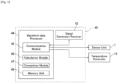
- the signal processing unit 40 includes a signal generator and a signal receiver (hereinafter the set of the signal generator and the signal receiver is referred as the "signal generator/receiver") 42 and a waveform data processor 44.
- the waveform data processor 44 includes a communication module (communication logical circuit) 45, a calculation module (calculation logical circuit) 46, a comparison module (comparison logical circuit) 47, and a memory unit 48 for logical hardware resources of a computer system, as illustrated in FIG. 5 .
- the communication module 45 of the waveform data processor 44 sends a predetermined "set temperature” or a control temperature of the Peltier element 12 to the temperature controller 16 and instructions for flowing a gas into the sensor cell 31 to the sensor unit 1.
- the communication module 45 sends instructions to the signal generator/receiver 42 so that the signal generator/receiver 42 transmits a burst signal to the sensor electrode 22 of the ball sensor 2 so that the sensor electrode 22 can excite the collimated beam 21 of a SAW propagating around the piezoelectric ball 20, and receives burst signals of the collimated beam 21 through the sensor electrode 22 after the collimated beam 21 has propagated a predetermined number of turns around the piezoelectric ball 20.
- the signal generator/receiver 42 transmits waveform data of the burst signals to the waveform data processor 44.
- the calculation module 46 of the waveform data processor 44 calculates the water concentration w and the ball temperature T B by using first and second relative changes in delay times of the first and second frequencies, respectively, using the waveform data of the burst signals.
- the comparison module 47 of the waveform data processor 44 compares the calculated ball temperature T B with the value of the previously measured ball temperature T B in order to determine whether the measurement has been implemented in thermal equilibrium.
- the memory unit 48 of the waveform data processor 44 stores a program for allowing the waveform data processor 44 to implement processing of the waveform data for calculating the water concentration w and the ball temperature T B . Also, the memory unit 48 stores the set temperature of the Peltier element 12, the calculated ball temperature T B , the previously measured ball temperature T B , and data obtained during the calculation and analysis thereof during the operation of the waveform data processor 44.
- the waveform data processor 44 may be part of central processing unit (CPU) of a general purpose computer system, such as a personal computer (PC) and the like.
- the waveform data processor 44 may include an arithmetic logic unit (ALU) that performs arithmetic and logic operations, a plurality of registers that supply operands to the ALU and store the results of ALU operations, and a control unit that orchestrates the fetching (from memory) and execution of instructions by directing the coordinated operations of the ALU.
- ALU arithmetic logic unit
- the communication module 45, the calculation module 46, and the comparison module 47 implementing the ALU may be discrete hardware resources such as logical circuit blocks or the electronic circuitry contained on a single integrated circuit (IC) chip, or alternatively, may be provided by virtually equivalent logical functions achieved by software, using the CPU of the general purpose computer system.
- IC integrated circuit
- the program for the waveform data processor 44 for measuring the water concentration is not limited to being stored in the memory unit 48 which is installed in the waveform data processor 44.
- the program may be stored in an external memory.
- the program may be stored in a computer readable medium.
- the "computer readable medium” refers to a recording medium or a storage medium, such as an external memory unit of a computer, a semiconductor memory, a magnetic disk, an optical disk, a magneto optical disk, and a magnetic tape, on which the program can be recorded.
- the principle of measurement executed in the waveform data processor 44 will be described as follows, representing a first relative changes in delay time (DTC) by the Greek-alphabet as Delta-ti, and a second relative DTC by the Greek-alphabet as Delta-t 2 , as a macroscopic change in the value of a variable is represented by Greek-letter Delta in mathematics or science.
- Delta-t 1 is defined as Delta-Taui/Taui at the first frequency f 1
- Delta-t 2 is defined as Delta-Tau 2 /Tau 2 at the second frequency f 2 .
- the Greek-alphabets Tau 1 and Tau 2 are delay times of the SAW at the first and second frequencies f 1 and f 2 , respectively, during propagating a predetermined number of turns without moisture adsorbed on the sensitive film 23, and Delta-Tau 1 and Delta-Tau 2 are delay time changes of the delay times Tau 1 and Tau 2 due to both the water concentration and the ball temperature change.
- Each of delay times Tau 1 and Tau 2 at each turn is obtained as a zero cross time closest to the maximum magnitude of a real part of wavelet transform of the received burst signals at the turns (refer to NPL 2).
- the water concentration w and the ball temperature T B can be simultaneously obtained by Eqs. (3) and (4), respectively.
- step S100 the signal generator/receiver 42a transmits the burst signal to the ball sensor 2, so as to exite the collimated beam 21 of the SAW.
- step S101 after the collimated beam 21 has propagated a predetermined number of turns around the ball sensor 2, the signal generator/receiver 42 receives the burst signals of the collimated beam 21 through the ball sensor 2. Waveform data of the burst signals is transmitted to the waveform data processor 44.
- step S102 the waveform data processor 44 calculates the first and second relative changes Delta-ti, Delta-t 2 of the first and second frequencies f 1 , f 2 , respectively, using the waveform data. Then, the first and second objective changes Delta-t W , Delta-t T due to the water concentration w and the ball temperature T B , respectively, are calculated using the first and second relative changes Delta-ti, Delta-t 2 .
- step S103 the waveform data processor 44 calculates the ball temperature T B by Eq. (4) using the second objective change Delta-tr.
- step S104 a temperature change Delta-T of the ball temperature T B from the previous measurement cycle is compared with a threshold value Delta-Tc that is a criterion of thermal equilibrium. In the test measurements, the threshold value Delta-Tc is temporarily set as 20°C, the condition Delta-T ⁇ Delta-Tc is always satisfied for each measurement cycle of 12 seconds.
- step S105 the gas concentration w is calculated by Eq. (3).
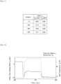
- the second objective change Delta-t T has been plotted as a function of the ball temperature T B , by changing the set temperature of the Peltier element 12.
- the ball temperature T B has assumed to be identical to the monitoring temperature T th of the holder 11 when the gas flow rate v is zero.
- the temperature coefficient A 1 can be defined by the slope of the fitting line
- the reference temperature T REF can be defined by a particular ball temperature where the second objective change Delta-t T is zero.
- the temperature coefficient A 1 and the reference temperature T REF can be determined as - 24.25 ppm/°C, and 24.06°C.
- the error of other ball temperatures calculated using Eq. (5) has been evaluated to be less than 0.24 %.
- the ball temperature may be measured with high sensitivity and reliability.
- the ball temperature T B calculated by Eq. (5) has been compared with the monitoring temperature T th measured by the thermistor 13. As illustrated in Fig. 8 , when the specific set temperature of the Peltier element 12 has been changed from 34°C to 24°C, the ball temperature T B has been delayed by about 0.5 minute from the monitoring temperature T th and has not reached 24°C even after three minutes. This phenomenon is due to a large heat capacity of the adapter 14 made of stainless steel plate. Therefore, it is necessary to measure the water concentration with thermal equilibrium for precise measurement using viscoelastic property of the sensitive film 23.
- the threshold value Delta-Tc In order to avoid an error caused by the non-equilibrium phenomenon, it is desirable to set the threshold value Delta-Tc to a smaller value, for example 0.1°C or less. On the contrary, it is desirable to set the threshold value Delta-Tc to a larger value, for example 10°C or more, to continue measurement without interruption.
- the water concentration w in a nitrogen (N 2 ) gas flow has been changed by the sequence of 1.3, 234, 1.3, 590, 1.3, 1180, 1.3 ppbv, where each water concentration w has been evaluated using the cavity ring down spectroscopy (CRDS) (refer to S. Hagihara, et al. Japanese Journal of Applied Physics, Vol.53 (2014) 07KD08 ).
- the set temperature of the Peltier element 12 has been changed between 24°C and 14°C.
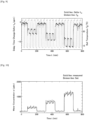
- the first objective change Delta-t w due to water concentration w and the ball temperature T B have been measured as illustrated in FIGs. 9 and 11 . As illustrated in FIG.
- the ball temperature T B has precisely reproduced the temperature setting, and not disturbed by the changes of the water concentration w, illustrating validity of Eq. (4) or (5).
- the first objective change Delta-t w has been changed with the water concentration w and also with the ball temperature T B .
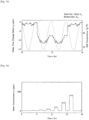
- FIG. 12 illustrates the transition of the first objective change Delta-t w and the ball temperature T B when the water concentration w has been changed from 1.3 to 1180 ppbv.
- the first DTC Delta-t w has illustrated rather complex behavior due to the changes of water concentration w and the ball temperature T B .
- the water concentration w has almost correctly reproduced the set value.
- the variation of the water concentration w near temperature jump where the ball temperature T B drastically changes between 14°C and 24°C is a subject matter to be solved for improvement of accuracy.
- the temperature jump may occur when the temperature change Delta-T of the ball temperature T B from the previous measurement cycle is larger than 0.1°C.
- the variation of the water concentration w might be due to adsorption and/or desorption of water in the sensor cell 31 and the tubing 36, the variation of the water concentration w may occur when the temperature change Delta-T of the ball temperature T B is too large.
- the other test measurement has been implemented with the threshold value Delta-Tc of 0.08°C.
- the water concentration w in the N 2 gas flow has been changed by the sequence of 3.39, 14.36, 3.39, 41.22, 3.39, 85.74, 3.39, 174.2, 3.39, 434.7, 3.39, 870.4, 3.39 ppbv, evaluated using the CRDS.
- the ball temperature T B has been changed between 24°C and 14°C every 15 minutes by using the Peltier element 12.
- the measured ball temperature T B has reproduced the temperature setting.
- FIG. 15 it is known that the ball temperature T B has been kept at around 14°C for about five minutes, changed from 14°C to 24°C in about ten minutes, and kept at around 24°C for about five minutes.
- the first objective change Delta-t w due to the water concentration w has been changed with the water concentration w and also with the ball temperature T B .
- the threshold value Delta-Tc has been set 0.08°C in step S104 of the flow chart illustrated in FIG. 6 , and the equilibrium condition Delta-T ⁇ Delta-Tc has been satisfied in the duration where the ball temperature T B has been kept at around 14°C or 24°C for about five minutes.
- the water concentration w can be obtained using Eq. (8).
- the variation of the measured water concentration w near the temperature jump can be decreased compared with that in FIGs. 10 and 13 .
- FIG. 18 shows also comparison between the set concentration values, and measured concentration values averaged over 60 minutes. As illustrated in FIG. 18 , it is understood that the agreement between set and measured concentration values is remarkable. Therefore, according to the first embodiment, it is possible to achieve reliability of the concentration measurement even under varying temperature.
- the communication module 45 of the waveform data processor 44 transmits a specific set temperature of the Peltier element 12 to the temperature controller 16 illustrated in FIG. 1 .
- the ball temperature is controlled by the Peltier element 12 with the specific set temperature, and the thermistor 13 inserted in the holder 11 monitors the temperature of the holder 11.
- a gas containing water vaper is flowed into the sensor cell 31 through the tubing 36.
- step S100 in accordance with the instruction sent from the communication module 45, a burst signal is transmitted to the sensor electrode 22 from the signal generator/receiver 42, so as to exite the collimated beam 21 of the SAW.
- the collimated beam 21 propagates repeatedly through the orbital path on the piezoelectric ball 20 while passing through the sensitive film 23 allocated on the orbital path.
- step S101 after the collimated beam 21 has propagated a predetermined number of turns, for example 50 turns, around the piezoelectric ball 20, the signal generator/receiver 42 receives burst signals of the collimated beam 21 through the sensor electrode 22. Through the communication module 45, waveform data of the burst signals is transmitted to the waveform data processor 44 illustrated in FIG. 4 .
- step S102 the calculation module 46 of the waveform data processor 44 calculates the first and second relative changes Delta-ti, Delta-t 2 of the first and second frequencies f 1 , f 2 , respectively, by the waveform data of the burst signals. Then, the first and second objective changes Delta-t w , Delta-t T due to the water concentration w and the ball temperature T B , respectively, are calculated using the first and second relative changes Delta-t 1 , Delta-t 2 .
- step S103 the calculation module 46 of the waveform data processor 44 calculates the ball temperature T B using the second objective change Delta-t T .
- step S104 a temperature change Delta-T of the ball temperature T B from the previous measurement cycle is compared with a threshold value Delta-Tc by the comparison module 47 of the waveform data processor 44.
- the threshold value Delta-Tc is set as 0.08°C.
- step S105 the gas concentration w is calculated by the calculation module 46 and recorded in the memory unit 48 as a new measured value.
- the temperature change Delta-T is larger than the threshold value Delta-Tc, it is determined that the thermal equilibrium needed for precise measurement of viscoelastic property of the sensitive film is not realized.
- the water concentration w in the previous cycle is still effective, and processing returns to step S100, so as to start a next cycle of the measurement.
- the water concentration w and the ball temperature T B of the ball sensor 2 can be simultaneously measured with high sensitivity and reliability even under varying temperature.
- the change of the ball temperature T B is rather slow and delayed by about 0.5 minute compared with the monitoring temperature T th of the thermistor 13 in the first embodiment.
- the ball temperature T B may not reach the desired set temperature even after three minutes.
- One of the reasons is the large heat capacity of the adapter 14 made of stainless steel plate.
- the thermistor 13 should be installed as close to the ball sensor 2 as possible. However, since leakage of moisture from the outside air should be avoided, the thermistor 13 cannot be installed in the sensor cell 31.
- the ball temperature T B is available using the delay times Tau 1 and Tau 2 of the SAW and the relative changes Delta-Tau 1 and Delta-Tau 2 of the delay times Tau 1 and Tau 2 . More specifically, the ball temperature T B calculated by the waveform data processor 44 may be used to control the Peltier element 12 instead of the monitoring temperature T th by the thermistor 13. Thus, the ball sensor 2 itself may be used as a precise thermometer to monitor the ball temperature T B .
- the temperature control requires the use of the ball temperature T B as a control signal, and when the ball temperature T B is used as the control signal, the performance of the system for measuring water concentration pertaining to the first embodiment can be improved, compared with the configuration, in which the commercial temperature controller is used. This improvement is realized using an apparatus illustrated in Fig. 19 .
- the temperature controller 16 includes a command interpreter 18 for receiving a specific set temperature of the Peltier element 12 and a calculated ball temperature T B from the waveform data processor 44.
- the second embodiment differs from the first embodiment in that the command interpreter 18 is provided in the waveform data processor 44.
- Other configurations are almost same as in the first embodiment, so duplicated descriptions are omitted.
- the waveform data processor 44 sets a temperature in the temperature controller 16 for controlling the Peltier element 12.
- the signal generator/receiver 42 transmits a burst signal to the ball sensor 2, and receives burst signals of the collimated beam 21 after the collimated beam 21 has propagated a predetermined number of turns around the piezoelectric ball 20. Subsequently, the signal generator/receiver 42 sends the waveform data of the burst signals to the waveform data processor 44.
- the waveform data processor 44 applies a signal processing to the waveform data using Eqs. (4) and (5), so as to obtain a ball temperature T B as a calculated temperature.
- the calculated ball temperature T B is sent to the command interpreter 18 using the Recommended Standard 232 version C (RS232C) communication protocol defined by the Electronic Industries Association (EIA).
- RS232C Recommended Standard 232 version C
- the temperature controller 16 sends a heating or cooling current to the Peltier element 12 in accordance with the proportional-integral-differential (PID) control algorithm.
- PID proportional-integral-differential
- FIG. 20A illustrates the temperature control according to the first embodiment, in which the monitoring temperature T th by the thermistor 13 has been used as a control signal.
- FIG. 20B illustrates the temperature control according to the second embodiment, in which the calculated ball temperature T B by the waveform data processor 44 has been used as a control signal.
- the response time is about 7.0 min when the specific set temperature has been changed from 24°C to 14°C, and about 4.65 min when the specific set temperature has been changed from 14°C to 24°C, respectively.
- the response time is about 3.85 min when the specific set temperature has been changed from 24°C to 14°C, and about 3.1 min when the specific set temperature has been changed from 14°C to 24°C, respectively.
- the temperature control unit 10 is used for controlling temperature of the ball sensor 2.
- the temperature control for the ball sensor 2 is not always necessary.
- the measurement system may include the sensor unit 1 and the signal processing unit 40.
- the trace moisture sensor has been described as a gas sensor in the first and second embodiments.
- the present invention is applicable not only to the trace moisture sensor but also to sensors for various kinds of gas molecules, such as hydrogen molecules, oxygen molecules, volatile organic compound molecules, and the like.
- gas molecules such as hydrogen molecules, oxygen molecules, volatile organic compound molecules, and the like.
- a sensitive film 23 of a hydrogen gas sensor a palladium (Pd) film or a Pd compound film may be used.
- Pd palladium
Landscapes
- Physics & Mathematics (AREA)
- Chemical & Material Sciences (AREA)
- Life Sciences & Earth Sciences (AREA)
- Health & Medical Sciences (AREA)
- Analytical Chemistry (AREA)
- Biochemistry (AREA)
- General Health & Medical Sciences (AREA)
- General Physics & Mathematics (AREA)
- Immunology (AREA)
- Pathology (AREA)
- Acoustics & Sound (AREA)
- Engineering & Computer Science (AREA)
- Food Science & Technology (AREA)
- Medicinal Chemistry (AREA)
- Combustion & Propulsion (AREA)
- Investigating Or Analyzing Materials By The Use Of Ultrasonic Waves (AREA)
Description
- The present invention relates to a system and a method for simultaneously measuring a gas concentration and a ball temperature using a ball surface acoustic wave (SAW) sensor.
- Earlier piezoelectric gas sensors, such as planar SAW sensors, utilize the propagation property that amplitude and phase of the exited SAW change when passing through a sensitive film in which elastic characteristics are changed by adsorbing gas molecules. However, diffraction occurs when waves of a finite width are propagating, and the SAW on the planar SAW sensor is attenuated by diffraction loss. Therefore, because of the diffraction loss, there is a limit to the propagation distance of the SAW, and measurement accuracy of gas concentration is limited.
- As recited in non-patent literatures (NPLs) 1 and 2, a ball SAW sensor (hereinafter called "ball sensor") has been developed and applied to a trace moisture sensor. In the ball sensor, the SAW excited on a spherical surface with a specific condition may be naturally collimated, and multiple roundtrips along the equator of the ball can be realized. Thus, the ball sensor based on this effect may provide high performance, such as high sensitivity and wide sensing range.
- Since the sensitivity of the piezoelectric gas sensor also depends on temperature of the sensor, measured gas concentration is disturbed when the sensor temperature is largely changed. However, it is not easy to measure the sensor temperature, when it is not possible to insert a thermometer into the sensor cell. The ball sensor also has the same problem.
Patent literature (PL) 1 discloses an electrical signal processing device in which narrowband frequency filtering is applied to a cyclic waveform in a delay-line-type-SAW sensor capable of transmitting and receiving a plurality of frequencies, two frequencies (f1, f2) (f2 > f1) are extracted, undersampling is applied to the two frequencies at a frequency lower than two times f1, and the obtained aliasing is used to determine the delay time. -
- [NPL 1] K. Yamanaka, et al.: Institute of Electrical and Electronics Engineers (IEEE) Transactions on Ultrasonics, Ferroelectrics, and Frequency Control, vol.53 (2006) pp.793
- [NPL 2] T. Tsuji, et al.: Proceedings of Symposium on Ultrasonic Electronics, 36 (2015) 3P3-6-1-2
- [PL1]
WO 2016/084917 A1 - In view of the above problems, an object of the present invention is to provide a system and a method for measuring a gas concentration, which can simultaneously measure the ball temperature of the ball sensor and the gas concentration, with high sensitivity and reliability even under varying temperature.
- A first aspect of the present invention inheres in a system for measuring a gas concentration, as defined in
claim 1. - A second aspect of the present invention inheres in a method for measuring a gas concentration, as defined in claim 7.
- According to the present invention, it is possible to provide the system and the method for measuring gas concentration, which can simultaneously measure the ball temperature of the ball sensor and the gas concentration, with high sensitivity and reliability even under varying temperature.
-
- [
Fig. 1 ]
FIG. 1 is a schematic cross sectional view illustrating an example of a system for measuring water concentration according to a first embodiment of the present invention; - [
Fig. 2 ]
FIG. 2 is a schematic view illustrating an example of a ball sensor used in the system for measuring the water concentration according to the first embodiment of the present invention; - [
Fig. 3 ]
FIG. 3 is a schematic view illustrating an example of a sensor electrode of the ball sensor used in the system for measuring the water concentration according to the first embodiment of the present invention; - [
Fig. 4 ]
FIG. 4 is a block diagram illustrating an example of temperature control and signal transmission in the system for measuring the water concentration according to the first embodiment of the present invention; - [
Fig. 5 ]
FIG. 5 is a block diagram illustrating an example of the signal processing unit in the system for measuring the water concentration according to the first embodiment of the present invention; - [
Fig. 6 ]
FIG. 6 is a flow chart illustrating an example of a method for measuring the water concentration according to the first embodiment of the present invention; - [
Fig. 7 ]
FIG. 7 is a diagram illustrating a relationship between the delay time change due to the ball temperature and the ball temperature according to the first embodiment of the present invention; - [
Fig. 8 ]
Fig. 8 is a diagram illustrating temperature jumps of the monitoring temperature and the ball temperature according to the first embodiment of the present invention; - [
Fig. 9 ]
Fig. 9 is a diagram illustrating time changes of the delay time change due to the water concentration and the ball temperature while changing the water concentration and the set temperature according to the first embodiment of the present invention; - [
Fig. 10 ]
Fig. 10 is a diagram illustrating time changes of the set value of the water concentration and the measured value of the water concentration according to the first embodiment of the present invention; - [
Fig. 11 ]
Fig. 11 is a table illustrating summarized results ofFIGs. 9 and 10 ; - [
Fig. 12 ]
Fig. 12 is a diagram enlarging the range of time from 550 min to 600 min inFIG. 9 ; - [
Fig. 13 ]
Fig. 13 is a diagram enlarging the range of time from 550 min to 600 min inFIG. 10 ; - [
Fig. 14 ]
Fig. 14 is a diagram illustrating time changes of the delay time change due to the water concentration and the ball temperature while changing the water concentration and the set temperature according to the first embodiment of the present invention; - [
Fig. 15 ]
Fig. 15 is a diagram enlarging the range of time from 12 min to 14 min inFIG. 14 ; - [
Fig. 16 ]
Fig. 16 is a diagram illustrating the water concentration evaluated from the results ofFIG. 14 ; - [
Fig. 17 ]
Fig. 17 is a diagram enlarging the range of time from 12 min to 14 min inFIG. 16 ; - [
Fig. 18 ]
Fig. 18 is a diagram illustrating a relationship between the measured water concentration and the set water concentration obtained fromFIG. 16 ; - [
Fig. 19 ]
Fig. 19 is a block diagram illustrating an example of temperature control and signal transmission in a system for measuring the water concentration according to a second embodiment of the present invention; - [
Fig. 20A ]
Fig. 20A is a diagram illustrating the time changes of the ball temperature according to the first embodiment of the present invention; and - [
Fig. 20B ]
Fig. 20B is a diagram illustrating the time changes of the ball temperature according to the second embodiment of the present invention. - First and second embodiments of the present invention will be described below with reference to the drawings. In the descriptions of the following drawings, the same or similar reference numerals are assigned to the same or similar portions. However, the drawings are diagrammatic, and attention should be paid to a fact that the relations between thicknesses and plan view dimensions, the configuration of the apparatus and the like differ from the actual data. Thus, the specific thicknesses and dimensions should be judged by considering the following descriptions. Also, even between the mutual drawings, the portions in which the relations and rates between the mutual dimensions are different are naturally included. Also, the first and second embodiments as described below exemplify the apparatuses and methods for embodying the technical ideas of the present invention, and in the technical ideas of the present invention, the materials, shapes, structures, arrangements and the like of configuration parts are not limited to the followings. In the following description, the "horizontal" direction or the "vertical" direction is simply assigned for convenience of explanation and does not limit the technical spirit of the present invention. Therefore, for example, when the plane of paper is rotated 90 degrees, the "horizontal" direction is changed to the "vertical" direction and the "vertical" direction is changed to the "horizontal" direction. When the plane of paper is rotated 180 degrees, the "left" side is changed to the "right" side and the "right" side is changed to the "left" side. Therefore, various changes can be added to the technical ideas of the present invention, within the technical scope prescribed by claims.
- As illustrated in
FIGs. 1 and2 , a system for measuring water concentration pertaining to a first embodiment of the present invention includes asensor unit 1, atemperature controller 16, and asignal processing unit 40. Thesensor unit 1 has aball sensor 2 embedded in atubular sensor cell 31, which is fixed on a plate-shapedadapter 14 disposed on a block-shapedholder 11. As theball sensor 2 has spherical shape, with a tubular configuration, the inner structure of thesensor cell 31 has a concave configuration for mounting a lower portion of theball sensor 2. An electrode-holder base 32 is fixed on thesensor cell 31, such that the bottom of the electrode-holder base 32 is inserted in an inner wall of a window, which is vertically cut at the top wall of thetubular sensor cell 31. An opening of a canal, which penetrates vertically through the bottom of the electrode-holder base 32, partially covers an upper portion of theball sensor 2. Furthermore, the electrode-holder base 32 is capped by a sensor-cell cap 33. - The
ball sensor 2 is connected to a rod-shapedexternal electrode 35 through acontact pin 35a along a vertical direction via the canal at the bottom of the electrode-holder base 32. Theexternal electrode 35 is held in a hollow space of a vertically alignedcylindrical electrode holder 34, the bottom of which is inserted in an inner portion of the sensor-cell cap 33. A gas-containing trace-moisture or "the target gas-to-be-measured" is introduced into thesensor cell 31 through a horizontally alignedtubing 36 with a gas flow rate v, so that the target gas-to-be-measured can touch the surface of theball sensor 2. The gas flow rate v is typically 0.1 L/min to 1 L/min. - As illustrated in
FIG. 2 , theball sensor 2 may have asensor electrode 22 and asensitive film 23, which are arranged in predetermined areas on the surface of a homogeneouspiezoelectric ball 20. As a three-dimensional base body, thepiezoelectric ball 2 provides a homogeneous material sphere, on which a circular orbital band for propagating a SAW can be defined. Thesensor electrode 22 generates a collimatedbeam 21 of the SAW, which includes a fundamental wave of a first frequency and a harmonic wave of a second frequency, propagates repeatedly through the circular orbital path defined on thepiezoelectric ball 20 while passing through thesensitive film 23 deposited on the orbital path. Thesensitive film 23 can be formed on almost the entire surface of the orbital band, which defines the orbital path on the three-dimensional base body. Because thesensitive film 21 is configured to react with specific gas molecules, thesensitive film 21 adsorbs water vapor in the target gas-to-be-measured. - For the
piezoelectric ball 20, a crystal sphere, such as quartz, langasite (La3Ga5SiO14), lithium niobate (LiNbO3), lithium tantalate (LiTaO3), piezoelectric ceramics (PZT), bismuth germanium oxide (Bi12GeO20) and the like, may be used. For thesensitive film 23, a silica (SiOx) film and the like may be used. Thesensor electrode 22 may be deposited in an opening of thesensitive film 23, the opening exposes a part of the surface of thepiezoelectric ball 20, in a configuration such that the opening is formed on a part of the equator of the homogeneouspiezoelectric ball 20. For thesensor electrode 22, an interdigital electrode (IDT) using a chromium (Cr) film and the like may be used as an electroacoustic transducer. In the case of a sphere of single crystal such as the homogeneouspiezoelectric ball 20, a SAW orbiting route is limited to a specific orbital band having a constant width, depending on type of crystal material. The width of the orbital band may be increased or decreased depending on anisotropy of the crystal. - There are no diffraction losses during roundtrips around the
piezoelectric ball 20, and only propagation loss due to material attenuation. The collimatedbeam 21 is scheduled to propagate many turns passing through thesensitive film 23, which is configured to adsorb water molecules. Because the adsorbed water molecules change the propagation characteristic of the SAW, the changes due to adsorbed water molecules on thesensitive film 23 can be integrated every turn through the multiple roundtrips. Thus, even though thesensitive film 23 may be so thin as to adsorb the small amount of the water vapor, measurement accuracy of water concentration may be increased. - The suitable relationship between the first frequency f1 of the fundamental wave and the second frequency f2 of the harmonic wave shall be represented by f2 = nf1, where n = 3 or 5. That is, in the system for measuring water concentration pertaining to the first embodiment of the present invention, the harmonic wave is the third-order harmonic wave or the fifth-order harmonic wave. Thus, when the first frequency f1 is 80 MHz, the second frequency f2 is 240 MHz for the third-order harmonic wave or 400 MHz for the fifth-order harmonic wave. Appropriate range of the first frequency f1 for the
piezoelectric ball 20 of 3.3 millimeters diameter may be from 60 MHz to 100 MHz, and the most suitable first frequency f1 may be 80 MHz. The first frequency f1 is inversely proportional to the diameter of thepiezoelectric ball 20. - For example, the
ball sensor 2 may be fabricated as described below. A pattern of an IDT of about 150 nanometers thick Cr film is deposited on a surface of a quartz ball having a diameter of 3.3 millimeters. As illustrated inFIG. 3 , the IDT has a pair ofbus bars electrode fingers electrode fingers electrode finger - This IDT on the quartz ball having 3.3 millimeters diameter can generate 80 MHz SAW as a fundamental wave and 240 MHz SAW as a third-order harmonic wave. Then a silica film is synthesized by using a sol-gel method and coated on the surface of the quartz ball as follows: 3.47 grams of tetraethoxysilane (TEOS), 0.75 grams of isopropanol (IPA), and 1.50 grams of 0.1N hydrochloric acid (HCl) are mixed and stirred by sonication (27, 45, 100 kHz, 60 minutes). TEOS is polymerized by hydrolysis and resulted in SiOx. After sonication, the mixture is diluted with IPA and 0.5 mass% SiOx solution is obtained. The surface of propagation route of SAW is coated with the SiOx solution using a spin coating. Condition of the spin coating is 3000 rpm for 20 seconds. The thickness of SiOx film is confirmed as 1029 nanometers from measurement using interference microscope.
- An RF voltage is applied to the
sensor electrode 22 via an electrode pad (not illustrated) arranged around the north pole (top of thepiezoelectric ball 20 inFIG. 2 ) using thecontact pin 35a attached on the bottom of theexternal electrode 35. Another electrode pad (not illustrated) arranged around the south pole (bottom of thepiezoelectric ball 20 inFIG. 2 ) is in contact with the groundedsensor cell 31. - As illustrated in
FIG. 1 , thetemperature controller 16 is connected to aPeltier element 12, which is held in a lower portion of theholder 11 at a position just below theball sensor 2, and athermistor 13 is inserted in theholder 11 at a side position of theholder 11. Furthermore, atemperature controller 16 is connected to thethermistor 13. ThePeltier element 12 is used for heating and cooling theball sensor 2 in thesensor cell 31 through theadapter 14. Thethermistor 13 is used for detecting a monitoring temperature Tth of theholder 11. Thetemperature controller 16 controls thePeltier element 12 by using the monitoring temperature Tth. As illustrated inFIG. 1 , thethermistor 13 cannot be directly inserted into thesensor cell 31 to prevent leakage of gases through thesensor cell 31. Note that, although thethermistor 13 is used for detecting the monitoring temperature Tth in the first embodiment, but other thermometers, such as a thermocouple and the like, may be used. - The
signal processing unit 40, as illustrated inFIG. 4 , includes a signal generator and a signal receiver (hereinafter the set of the signal generator and the signal receiver is referred as the "signal generator/receiver") 42 and awaveform data processor 44. Thewaveform data processor 44 includes a communication module (communication logical circuit) 45, a calculation module (calculation logical circuit) 46, a comparison module (comparison logical circuit) 47, and amemory unit 48 for logical hardware resources of a computer system, as illustrated inFIG. 5 . Thecommunication module 45 of thewaveform data processor 44 sends a predetermined "set temperature" or a control temperature of thePeltier element 12 to thetemperature controller 16 and instructions for flowing a gas into thesensor cell 31 to thesensor unit 1. - Moreover, the
communication module 45 sends instructions to the signal generator/receiver 42 so that the signal generator/receiver 42 transmits a burst signal to thesensor electrode 22 of theball sensor 2 so that thesensor electrode 22 can excite the collimatedbeam 21 of a SAW propagating around thepiezoelectric ball 20, and receives burst signals of the collimatedbeam 21 through thesensor electrode 22 after the collimatedbeam 21 has propagated a predetermined number of turns around thepiezoelectric ball 20. The signal generator/receiver 42 transmits waveform data of the burst signals to thewaveform data processor 44. - The
calculation module 46 of thewaveform data processor 44 calculates the water concentration w and the ball temperature TB by using first and second relative changes in delay times of the first and second frequencies, respectively, using the waveform data of the burst signals. Thecomparison module 47 of thewaveform data processor 44 compares the calculated ball temperature TB with the value of the previously measured ball temperature TB in order to determine whether the measurement has been implemented in thermal equilibrium. Thememory unit 48 of thewaveform data processor 44 stores a program for allowing thewaveform data processor 44 to implement processing of the waveform data for calculating the water concentration w and the ball temperature TB. Also, thememory unit 48 stores the set temperature of thePeltier element 12, the calculated ball temperature TB, the previously measured ball temperature TB, and data obtained during the calculation and analysis thereof during the operation of thewaveform data processor 44. - The
waveform data processor 44 may be part of central processing unit (CPU) of a general purpose computer system, such as a personal computer (PC) and the like. Thewaveform data processor 44 may include an arithmetic logic unit (ALU) that performs arithmetic and logic operations, a plurality of registers that supply operands to the ALU and store the results of ALU operations, and a control unit that orchestrates the fetching (from memory) and execution of instructions by directing the coordinated operations of the ALU. Thecommunication module 45, thecalculation module 46, and thecomparison module 47 implementing the ALU may be discrete hardware resources such as logical circuit blocks or the electronic circuitry contained on a single integrated circuit (IC) chip, or alternatively, may be provided by virtually equivalent logical functions achieved by software, using the CPU of the general purpose computer system. - In addition, the program for the
waveform data processor 44 for measuring the water concentration is not limited to being stored in thememory unit 48 which is installed in thewaveform data processor 44. For example, the program may be stored in an external memory. Moreover, the program may be stored in a computer readable medium. By reading the computer readable medium in thememory unit 48 of the computer system, which includes thewaveform data processor 44, thewaveform data processor 44 implements coordinated operations for measuring water concentration, in accordance with a sequence of instructions recited in the program. Here, the "computer readable medium" refers to a recording medium or a storage medium, such as an external memory unit of a computer, a semiconductor memory, a magnetic disk, an optical disk, a magneto optical disk, and a magnetic tape, on which the program can be recorded. - The principle of measurement executed in the
waveform data processor 44 will be described as follows, representing a first relative changes in delay time (DTC) by the Greek-alphabet as Delta-ti, and a second relative DTC by the Greek-alphabet as Delta-t2, as a macroscopic change in the value of a variable is represented by Greek-letter Delta in mathematics or science. Delta-t1 is defined as Delta-Taui/Taui at the first frequency f1 and Delta-t2 is defined as Delta-Tau2/Tau2 at the second frequency f2. Here, the Greek-alphabets Tau1 and Tau2 are delay times of the SAW at the first and second frequencies f1 and f2, respectively, during propagating a predetermined number of turns without moisture adsorbed on thesensitive film 23, and Delta-Tau1 and Delta-Tau2 are delay time changes of the delay times Tau1 and Tau2 due to both the water concentration and the ball temperature change. Each of delay times Tau1 and Tau2 at each turn is obtained as a zero cross time closest to the maximum magnitude of a real part of wavelet transform of the received burst signals at the turns (refer to NPL 2). - The first and second relative changes Delta-t1, Delta-t2 are given by:


ball sensor 2, TREF is a reference temperature, and A1 and A2 are temperature coefficients at frequencies f1 and f2, respectively. - From Eqs. (1) and (2), a first objective change Delta-twin delay time due to gas concentration w is given by:


- Test measurements have been implemented using the fundamental wave and the third-order harmonic wave of the SAW, that is, f2 = 3f1, and without a gas flow. Each procedure of the test measurements will be described with reference to the flowchart illustrated in
FIG. 6 . In step S100, the signal generator/receiver 42a transmits the burst signal to theball sensor 2, so as to exite the collimatedbeam 21 of the SAW. In step S101, after the collimatedbeam 21 has propagated a predetermined number of turns around theball sensor 2, the signal generator/receiver 42 receives the burst signals of the collimatedbeam 21 through theball sensor 2. Waveform data of the burst signals is transmitted to thewaveform data processor 44. - In step S102, the
waveform data processor 44 calculates the first and second relative changes Delta-ti, Delta-t2 of the first and second frequencies f1, f2, respectively, using the waveform data. Then, the first and second objective changes Delta-tW, Delta-tT due to the water concentration w and the ball temperature TB, respectively, are calculated using the first and second relative changes Delta-ti, Delta-t2. In step S103, thewaveform data processor 44 calculates the ball temperature TB by Eq. (4) using the second objective change Delta-tr. In step S104, a temperature change Delta-T of the ball temperature TB from the previous measurement cycle is compared with a threshold value Delta-Tc that is a criterion of thermal equilibrium. In the test measurements, the threshold value Delta-Tc is temporarily set as 20°C, the condition Delta-T < Delta-Tc is always satisfied for each measurement cycle of 12 seconds. In step S105, the gas concentration w is calculated by Eq. (3). - As a result of the test measurements, the temperature coefficient ratio C has been determined as C=0.9875 by least square fitting of the second relative change Delta-t2 against the first relative change Delta-tr. Further, as illustrated in
FIG. 7 , the second objective change Delta-tT has been plotted as a function of the ball temperature TB, by changing the set temperature of thePeltier element 12. Here, the ball temperature TB has assumed to be identical to the monitoring temperature Tth of theholder 11 when the gas flow rate v is zero. From Eq. (4), the temperature coefficient A1 can be defined by the slope of the fitting line, and the reference temperature TREF can be defined by a particular ball temperature where the second objective change Delta-tT is zero. Thus, the temperature coefficient A1 and the reference temperature TREF can be determined as - 24.25 ppm/°C, and 24.06°C. - Substituting the temperature coefficient A1 and the reference temperature TREF into Eq.(4), ball temperature TB can be obtained as;

- The error of other ball temperatures calculated using Eq. (5) has been evaluated to be less than 0.24 %. As mentioned above, according to the first embodiment, the ball temperature may be measured with high sensitivity and reliability.
- In order to evaluate the effect of heat capacity of the
sensor cell 31, the ball temperature TB calculated by Eq. (5) has been compared with the monitoring temperature Tth measured by thethermistor 13. As illustrated inFig. 8 , when the specific set temperature of thePeltier element 12 has been changed from 34°C to 24°C, the ball temperature TB has been delayed by about 0.5 minute from the monitoring temperature Tth and has not reached 24°C even after three minutes. This phenomenon is due to a large heat capacity of theadapter 14 made of stainless steel plate. Therefore, it is necessary to measure the water concentration with thermal equilibrium for precise measurement using viscoelastic property of thesensitive film 23. In order to avoid an error caused by the non-equilibrium phenomenon, it is desirable to set the threshold value Delta-Tc to a smaller value, for example 0.1°C or less. On the contrary, it is desirable to set the threshold value Delta-Tc to a larger value, for example 10°C or more, to continue measurement without interruption. - As illustrated in
Fig. 10 , the water concentration w in a nitrogen (N2) gas flow has been changed by the sequence of 1.3, 234, 1.3, 590, 1.3, 1180, 1.3 ppbv, where each water concentration w has been evaluated using the cavity ring down spectroscopy (CRDS) (refer to S. Hagihara, et al. Japanese Journal of Applied Physics, Vol.53 (2014) 07KD08). At the same time, the set temperature of thePeltier element 12 has been changed between 24°C and 14°C. The first objective change Delta-tw due to water concentration w and the ball temperature TB have been measured as illustrated inFIGs. 9 and11 . As illustrated inFIG. 9 , the ball temperature TB has precisely reproduced the temperature setting, and not disturbed by the changes of the water concentration w, illustrating validity of Eq. (4) or (5). The first objective change Delta-tw has been changed with the water concentration w and also with the ball temperature TB. - Using the first objective change Delta-tw in the Table illustrated in
FIG. 11 , the right hand side term in Eq. (3) may be evaluated as;

- Substituting Eqs. (6) and (7) into Eq.(3), the water concentration w can be obtained as;

FIG. 10 , the water concentration w has almost correctly reproduced the set value in the sequence. Therefore, according to the first embodiment, it is possible to achieve the concentration measurement even with varying temperature. -
FIG. 12 illustrates the transition of the first objective change Delta-tw and the ball temperature TB when the water concentration w has been changed from 1.3 to 1180 ppbv. As illustrated inFIG. 12 , the first DTC Delta-tw has illustrated rather complex behavior due to the changes of water concentration w and the ball temperature TB. However, as illustrated inFIG. 13 , the water concentration w has almost correctly reproduced the set value. - Therefore, reliability of the concentration measurement even with varying temperature has been confirmed. However, the variation of the water concentration w near temperature jump where the ball temperature TB drastically changes between 14°C and 24°C is a subject matter to be solved for improvement of accuracy. The temperature jump may occur when the temperature change Delta-T of the ball temperature TB from the previous measurement cycle is larger than 0.1°C. Although the variation of the water concentration w might be due to adsorption and/or desorption of water in the
sensor cell 31 and thetubing 36, the variation of the water concentration w may occur when the temperature change Delta-T of the ball temperature TB is too large. - To solve the problem of the variation of the water concentration w near the temperature jump, the other test measurement has been implemented with the threshold value Delta-Tc of 0.08°C. The water concentration w in the N2 gas flow has been changed by the sequence of 3.39, 14.36, 3.39, 41.22, 3.39, 85.74, 3.39, 174.2, 3.39, 434.7, 3.39, 870.4, 3.39 ppbv, evaluated using the CRDS. At the same time, the ball temperature TB has been changed between 24°C and 14°C every 15 minutes by using the
Peltier element 12. - As illustrated in
FIG. 14 , the measured ball temperature TB has reproduced the temperature setting. As illustrated inFIG. 15 , it is known that the ball temperature TB has been kept at around 14°C for about five minutes, changed from 14°C to 24°C in about ten minutes, and kept at around 24°C for about five minutes. The first objective change Delta-tw due to the water concentration w has been changed with the water concentration w and also with the ball temperature TB. - The threshold value Delta-Tc has been set 0.08°C in step S104 of the flow chart illustrated in
FIG. 6 , and the equilibrium condition Delta-T < Delta-Tc has been satisfied in the duration where the ball temperature TB has been kept at around 14°C or 24°C for about five minutes. In this case, the right hand side term of Eq. (3) may be evaluated as Eqs. (6) and (7) with a = -9.00'LI0-6, Delta-e = 0.311 (eV). Substituting Eqs. (6) and (7) with a = -9.00'LI0-6, Delta-e = 0.311 (eV) into Eq.(3), the water concentration w can be obtained using Eq. (8). As illustrated inFIGs. 16 and17 , the variation of the measured water concentration w near the temperature jump can be decreased compared with that inFIGs. 10 and13 . -
FIG. 18 shows also comparison between the set concentration values, and measured concentration values averaged over 60 minutes. As illustrated inFIG. 18 , it is understood that the agreement between set and measured concentration values is remarkable. Therefore, according to the first embodiment, it is possible to achieve reliability of the concentration measurement even under varying temperature. - A measurement method of the water concentration according to the first embodiment will be described with reference to the flowchart illustrated in
FIG. 6 . First, thecommunication module 45 of thewaveform data processor 44 transmits a specific set temperature of thePeltier element 12 to thetemperature controller 16 illustrated inFIG. 1 . The ball temperature is controlled by thePeltier element 12 with the specific set temperature, and thethermistor 13 inserted in theholder 11 monitors the temperature of theholder 11. In accordance with the instruction sent from thecommunication module 45, a gas containing water vaper is flowed into thesensor cell 31 through thetubing 36. - In step S100, in accordance with the instruction sent from the
communication module 45, a burst signal is transmitted to thesensor electrode 22 from the signal generator/receiver 42, so as to exite the collimatedbeam 21 of the SAW. As illustrated inFIG. 2 , the collimatedbeam 21 propagates repeatedly through the orbital path on thepiezoelectric ball 20 while passing through thesensitive film 23 allocated on the orbital path. - In step S101, after the collimated
beam 21 has propagated a predetermined number of turns, for example 50 turns, around thepiezoelectric ball 20, the signal generator/receiver 42 receives burst signals of the collimatedbeam 21 through thesensor electrode 22. Through thecommunication module 45, waveform data of the burst signals is transmitted to thewaveform data processor 44 illustrated inFIG. 4 . - In step S102, the
calculation module 46 of thewaveform data processor 44 calculates the first and second relative changes Delta-ti, Delta-t2 of the first and second frequencies f1, f2, respectively, by the waveform data of the burst signals. Then, the first and second objective changes Delta-tw, Delta-tT due to the water concentration w and the ball temperature TB, respectively, are calculated using the first and second relative changes Delta-t1, Delta-t2. - In step S103, the
calculation module 46 of thewaveform data processor 44 calculates the ball temperature TB using the second objective change Delta-tT. - In step S104, a temperature change Delta-T of the ball temperature TB from the previous measurement cycle is compared with a threshold value Delta-Tc by the
comparison module 47 of thewaveform data processor 44. In the concentration measurement according to the first embodiment, the threshold value Delta-Tc is set as 0.08°C. - When the temperature change Delta-T is equal to or smaller than the threshold value Delta-Tc, in step S105, the gas concentration w is calculated by the
calculation module 46 and recorded in thememory unit 48 as a new measured value. On the other hand, when the temperature change Delta-T is larger than the threshold value Delta-Tc, it is determined that the thermal equilibrium needed for precise measurement of viscoelastic property of the sensitive film is not realized. Thus, the water concentration w in the previous cycle is still effective, and processing returns to step S100, so as to start a next cycle of the measurement. - In the measurement method according to the first embodiment, the water concentration w and the ball temperature TB of the
ball sensor 2 can be simultaneously measured with high sensitivity and reliability even under varying temperature. - As illustrated in
FIG. 8 , the change of the ball temperature TB is rather slow and delayed by about 0.5 minute compared with the monitoring temperature Tth of thethermistor 13 in the first embodiment. Moreover, the ball temperature TB may not reach the desired set temperature even after three minutes. One of the reasons is the large heat capacity of theadapter 14 made of stainless steel plate. Moreover, in order to monitor the ball temperature TB, thethermistor 13 should be installed as close to theball sensor 2 as possible. However, since leakage of moisture from the outside air should be avoided, thethermistor 13 cannot be installed in thesensor cell 31. - As mentioned in the first embodiment, the ball temperature TB is available using the delay times Tau1 and Tau2 of the SAW and the relative changes Delta-Tau1 and Delta-Tau2 of the delay times Tau1 and Tau2. More specifically, the ball temperature TB calculated by the
waveform data processor 44 may be used to control thePeltier element 12 instead of the monitoring temperature Tth by thethermistor 13. Thus, theball sensor 2 itself may be used as a precise thermometer to monitor the ball temperature TB. - Consequently, performance of the temperature control process may be ideal and the response of the ball temperature TB can be significantly faster. The temperature control requires the use of the ball temperature TB as a control signal, and when the ball temperature TB is used as the control signal, the performance of the system for measuring water concentration pertaining to the first embodiment can be improved, compared with the configuration, in which the commercial temperature controller is used. This improvement is realized using an apparatus illustrated in
Fig. 19 . - In a second embodiment of the present invention, as illustrated in
FIG. 19 , thetemperature controller 16 includes acommand interpreter 18 for receiving a specific set temperature of thePeltier element 12 and a calculated ball temperature TB from thewaveform data processor 44. The second embodiment differs from the first embodiment in that thecommand interpreter 18 is provided in thewaveform data processor 44. Other configurations are almost same as in the first embodiment, so duplicated descriptions are omitted. - During measurement, the
waveform data processor 44 sets a temperature in thetemperature controller 16 for controlling thePeltier element 12. The signal generator/receiver 42 transmits a burst signal to theball sensor 2, and receives burst signals of the collimatedbeam 21 after the collimatedbeam 21 has propagated a predetermined number of turns around thepiezoelectric ball 20. Subsequently, the signal generator/receiver 42 sends the waveform data of the burst signals to thewaveform data processor 44. Thewaveform data processor 44 applies a signal processing to the waveform data using Eqs. (4) and (5), so as to obtain a ball temperature TB as a calculated temperature. The calculated ball temperature TB is sent to thecommand interpreter 18 using the Recommended Standard 232 version C (RS232C) communication protocol defined by the Electronic Industries Association (EIA). - When the calculated ball temperature TB is lower or higher than the set temperature, the
temperature controller 16 sends a heating or cooling current to thePeltier element 12 in accordance with the proportional-integral-differential (PID) control algorithm. In the second embodiment, since the ball temperature TB is used as a control signal for controlling thePeltier element 12, the response of the ball temperature TB may be significantly faster compared with using the monitoring temperature Tth monitored by thethermistor 13. - The response time has been evaluated by the time required to reach the specific set temperature and to be stabilized within the temperature range of ±0.2°C from the set temperature.
FIGs. 20A and 20B illustrate the time changes of the ball temperature TB controlled by thePeltier element 12 when changing the specific set temperature of thePeltier element 12 from 24°C to 14°C at time t = 0 min, and from 14°C to 24°C at time t = 15 min.FIG. 20A illustrates the temperature control according to the first embodiment, in which the monitoring temperature Tth by thethermistor 13 has been used as a control signal.FIG. 20B illustrates the temperature control according to the second embodiment, in which the calculated ball temperature TB by thewaveform data processor 44 has been used as a control signal. - As illustrated in
FIG. 20A , the response time is about 7.0 min when the specific set temperature has been changed from 24°C to 14°C, and about 4.65 min when the specific set temperature has been changed from 14°C to 24°C, respectively. As illustrated inFIG. 20B , the response time is about 3.85 min when the specific set temperature has been changed from 24°C to 14°C, and about 3.1 min when the specific set temperature has been changed from 14°C to 24°C, respectively. Thus, it is understood fromFIGs. 20A and 20B , that the response of the ball temperature TB using the ball temperature TB as a control signal may be significantly faster compared with using the monitoring temperature Tth monitored by thethermistor 13. - As mentioned above, the present invention has been described on the basis of the first and second embodiments. However, the discussions and drawings that configure a part of this disclosure should not be understood to limit the present invention. From this disclosure, various variations, implementations and operational techniques would be evident for one skilled in the art.
- In the first and second embodiments, the
temperature control unit 10 is used for controlling temperature of theball sensor 2. However, when measurement is implemented at room temperature or in the temperature controlled chamber, the temperature control for theball sensor 2 is not always necessary. In such cases, the measurement system may include thesensor unit 1 and thesignal processing unit 40. - The trace moisture sensor has been described as a gas sensor in the first and second embodiments. However, the present invention is applicable not only to the trace moisture sensor but also to sensors for various kinds of gas molecules, such as hydrogen molecules, oxygen molecules, volatile organic compound molecules, and the like. For example, for a
sensitive film 23 of a hydrogen gas sensor, a palladium (Pd) film or a Pd compound film may be used. In this way, the present invention naturally includes various embodiments that are not noted here. Thus, the technical scope of the present invention is determined only by the appended claims. -
- 1 sensor unit
- 2 ball sensor (ball SAW sensor)
- 10 temperature control unit
- 11 holder
- 12 Peltier element
- 13 thermistor
- 14 adapter
- 16 temperature controller
- 18 command interpreter
- 20 piezoelectric ball
- 21 collimated beam
- 22 sensor electrode
- 23 sensitive film
- 31 sensor cell
- 32 electrode-holder base
- 33 sensor-cell cap
- 34 electrode holder
- 35 external electrode
- 36 tubing
- 40 signal processing unit
- 42 signal generator/receiver (signal generator and receiver)
- 44 waveform data processor
- 45 communication module
- 46 calculation module
- 47 comparison module
- 48 memory unit
Claims (12)
- A system for measuring a gas concentration, comprising:a ball sensor (2) having:a piezoelectric ball (20),a sensor electrode (22) configured to generate a collimated beam (21) of a surface acoustic wave including a fundamental wave of a first frequency and a harmonic wave of a second frequency, which propagates through an orbital path on the piezoelectric ball (20), anda sensitive film (23) deposited on the piezoelectric ball (20), configured to adsorb a target gas, the sensitive film (23) is arranged in a position where the collimated beam (21) of the surface acoustic wave passes through; anda signal processing unit (40) having:a signal generator configured to transmit a burst signal to the sensor electrode (22) so as to excite the collimated beam (21) propagating around the piezoelectric ball (20),a signal receiver configured to receive burst signals of the collimated beam (21) through the sensor electrode (22) after the collimated beam (21) has propagated a predetermined number of turns around the piezoelectric ball (20), anda waveform data processor (44) configured to calculate the gas concentration of the target gas and the ball temperature by first and second relative changes in delay times of the first and second frequencies, respectively, using waveform data of the burst signals,wherein, when calculating the gas concentration and the ball temperature, the waveform data processor (44) calculates first and second objective changes in delay times by the first and second relative changes, the first objective change due to the gas concentration, the second objective change due to the ball temperature.
- The system of claim 1, wherein the first relative change is calculated using a delay time of the fundamental wave and a change in the delay time of the fundamental wave due to both the gas concentration and the ball temperature, and
the second relative change is calculated using a delay time of the harmonic wave and a change in the delay time of the harmonic wave due to both the gas concentration and the ball temperature. - The system of claim 2, wherein the first and second relative changes are given by,

 Delta-t1 and Delta-t2 are the first and second relative changes at the first and second frequencies, respectively,Tau1 and Tau2 are the delay times of the fundamental wave and the harmonic wave, respectively, andDelta-Tau1 and Delta-Tau2 are the changes in delay times of the fundamental wave and the harmonic wave, respectively.
 - The system of claim 3, wherein the first and second objective changes are given by,

 Delta-tW and Delta-tT are the first and second objective changes, respectively,f1 and f2 are the first and second frequencies, respectively,C=A2/A1 is temperature coefficient ratio, andA1 and A2 are temperature coefficients at the first and second frequencies, respectively,
and wherein the ball temperature TB is given by TREF is a reference ball temperature where the second objective change Delta-tris zero.
 - The system according to any one of claims 1 to 4, wherein the harmonic wave is a third-order harmonic wave.
- The system according to any one of claims 1 to 5, wherein the target gas is water vapor and the sensitive film (23) is a silica film.
- A method for measuring a gas concentration using a ball sensor (2) having a sensor electrode (22) generating a surface acoustic wave and a sensitive film (23) adsorbing a target gas, on a piezoelectric ball (20), comprising:flowing a gas containing the target gas into a sensor cell (31) having the ball sensor (2) in place;transmitting a burst signal to the sensor electrode (22) so as to excite a collimated beam (21) of the surface acoustic wave including a fundamental wave of a first frequency and a harmonic wave of a second frequency, which propagates repeatedly through an orbital path on the piezoelectric ball (20) while passing through the sensitive film (23) deposited on the orbital path;receiving burst signals of the collimated beam (21) through the sensor electrode (22) after the collimated beam (21) has propagated a predetermined number of turns around the piezoelectric ball (20); andcalculating first and second relative changes in delay times of the first and second frequencies, respectively, by waveform data of the burst signals so as to calculate the gas concentration of the target gas and the ball temperature, wherein, when calculating the gas concentration and the ball temperature, a first objective change in the delay time due to the gas concentration and a second objective change in the delay time due to the ball temperature are calculated using the first and second relative changes.
- The method of claim 7, wherein the first relative change is calculated using a delay time of the fundamental wave and a change in the delay time of the fundamental wave due to both the gas concentration and the ball temperature, and
the second relative change is calculated using a delay time of the harmonic wave and a change in the delay time of the harmonic wave due to both the gas concentration and the ball temperature. - The method of claim 8, wherein the first and second relative changes are given by,

 Delta-t1 and Delta-t2 are the first and second relative changes at the first and second frequencies, respectively,Tau1 and Tau2 are the delay times of the fundamental wave and the harmonic wave, respectively, andDelta-Tau1 and Delta-Tau2 are the changes in delay times of the fundamental wave and the harmonic wave, respectively.
 - The method of claim 9, wherein the first and second objective changes are given by,

 Delta-tW and Delta-tT are the first and second objective changes, respectively,f1 and f2 are the first and second frequencies, respectively, C=A2/A1 is temperature coefficient ratio, andA1 and A2 are temperature coefficients at the first and second frequencies, respectively,
and wherein the ball temperature TB is given by TREF is a reference ball temperature where the second objective change Delta-tris zero.
 - The method to any one of claims 7 to 10, wherein the harmonic wave is a third-order harmonic wave.
- The method according to any one of claims 7 to 11, wherein the target gas is water vapor and the sensitive film is a silica film.
Applications Claiming Priority (2)
| Application Number | Priority Date | Filing Date | Title |
|---|---|---|---|
| US201662418428P | 2016-11-07 | 2016-11-07 | |
| PCT/JP2017/039994 WO2018084296A1 (en) | 2016-11-07 | 2017-11-06 | System, method and computer program product for measuring gas concentration |
Publications (3)
| Publication Number | Publication Date |
|---|---|
| EP3545293A1 EP3545293A1 (en) | 2019-10-02 |
| EP3545293A4 EP3545293A4 (en) | 2020-11-11 |
| EP3545293B1 true EP3545293B1 (en) | 2024-09-25 |
Family
ID=62075515
Family Applications (1)
| Application Number | Title | Priority Date | Filing Date |
|---|---|---|---|
| EP17866930.5A Active EP3545293B1 (en) | 2016-11-07 | 2017-11-06 | System, method and computer program product for measuring gas concentration |
Country Status (5)
| Country | Link |
|---|---|
| US (1) | US11333631B2 (en) |
| EP (1) | EP3545293B1 (en) |
| JP (1) | JP6805418B2 (en) |
| CN (1) | CN109891230B (en) |
| WO (1) | WO2018084296A1 (en) |
Families Citing this family (2)
| Publication number | Priority date | Publication date | Assignee | Title |
|---|---|---|---|---|
| CN111094968B (en) * | 2018-01-31 | 2022-09-06 | 球波株式会社 | System, method and computer program product for gas analysis |
| EP4194540A4 (en) * | 2020-08-17 | 2024-09-11 | Ball Wave Inc. | VIRUS TESTING DEVICE, VIRUS TESTING SYSTEM, VIRUS TESTING METHOD AND VIRUS TESTING PROGRAM |
Family Cites Families (10)
| Publication number | Priority date | Publication date | Assignee | Title |
|---|---|---|---|---|
| JPH0611492A (en) * | 1992-06-26 | 1994-01-21 | Koji Toda | Elastic surface wave device |
| CN2401891Y (en) * | 1999-11-30 | 2000-10-18 | 深圳市北南环保技术有限公司 | Cooking fume, smoke dust sampler |
| US20070041870A1 (en) * | 2003-03-26 | 2007-02-22 | Kazushi Yamanaka | Sensor head, gas sensor and sensor unit |
| US7267009B2 (en) * | 2005-04-14 | 2007-09-11 | Honeywell International Inc. | Multiple-mode acoustic wave sensor |
| WO2008056458A1 (en) * | 2006-11-10 | 2008-05-15 | Tohoku University | Gas analyzer and method of gas analysis |
| CN105375903B (en) * | 2007-11-20 | 2018-09-14 | 日本无线株式会社 | Surface acoustic wave device and equipment for measuring characteristics of liquid material |
| JP5397351B2 (en) * | 2010-08-23 | 2014-01-22 | 株式会社デンソー | Flow rate detector |
| CN103776524B (en) * | 2014-02-21 | 2016-02-10 | 南京大学 | A kind of method measuring strong focusing ultrasound non-linear sound-filed simulation |
| WO2016084917A1 (en) * | 2014-11-28 | 2016-06-02 | 国立大学法人東北大学 | Electrical signal processing device |
| CN205246126U (en) * | 2015-12-21 | 2016-05-18 | 北京华创维想科技开发有限责任公司 | Real -time online environmental quality monitoring devices who uses in subway |
-
2017
- 2017-11-06 JP JP2019542961A patent/JP6805418B2/en active Active
- 2017-11-06 WO PCT/JP2017/039994 patent/WO2018084296A1/en not_active Ceased
- 2017-11-06 CN CN201780066777.XA patent/CN109891230B/en active Active
- 2017-11-06 EP EP17866930.5A patent/EP3545293B1/en active Active
- 2017-11-06 US US16/347,598 patent/US11333631B2/en active Active
Non-Patent Citations (1)
| Title |
|---|
| YAMANAK KAZUSHI: "US62/418428", 28 May 2018 (2018-05-28), XP055847634, Retrieved from the Internet <URL:https://diplus.internal.epo.org/app/> * |
Also Published As
| Publication number | Publication date |
|---|---|
| CN109891230A (en) | 2019-06-14 |
| WO2018084296A1 (en) | 2018-05-11 |
| CN109891230B (en) | 2021-05-14 |
| EP3545293A4 (en) | 2020-11-11 |
| EP3545293A1 (en) | 2019-10-02 |
| JP2019532313A (en) | 2019-11-07 |
| US11333631B2 (en) | 2022-05-17 |
| US20190360966A1 (en) | 2019-11-28 |
| JP6805418B2 (en) | 2020-12-23 |
Similar Documents
| Publication | Publication Date | Title |
|---|---|---|
| Penza et al. | Relative humidity sensing by PVA-coated dual resonator SAW oscillator | |
| EP3662278B1 (en) | System, method and computer program product for gas analysis | |
| US4055072A (en) | Apparatus for measuring a sorbate dispersed in a fluid stream | |
| WO2005095947A1 (en) | Environment difference detector | |
| Mccann et al. | A lateral-field-excited LiTaO 3 high-frequency bulk acoustic wave sensor | |
| JP2007524853A (en) | Layered surface acoustic wave sensor | |
| EP3545293B1 (en) | System, method and computer program product for measuring gas concentration | |
| JPH0563732B2 (en) | ||
| JP2014025741A (en) | Surface acoustic wave sensor for detecting gas | |
| JP2008122105A (en) | Elastic wave sensor and detection method | |
| EP3752814B1 (en) | Standard-moisture generator, system using the standard-moisture generator, method for detecting abnormality in standard-moisture and computer program product for detecting the abnormality | |
| CA2549837A1 (en) | Sensor, sensor arrangement, and measuring method | |
| US11307176B2 (en) | Standard-moisture generator, system using the standard-moisture generator, method for detecting abnormality in standard-moisture and computer program product for detecting the abnormality | |
| RU2533692C1 (en) | Multiplexer acoustic array for "electronic nose" and "electronic tongue" analytical instruments | |
| Takeda et al. | Deep Sub-micro mol· mol-1 Water-Vapor Measurement by Dual-Ball SAW Sensors for Temperature Compensation | |
| JP2006275999A (en) | Surface acoustic wave device and method of using the same | |
| Trusty | A Temperature Compensated Lateral Field Excited Lithium Tantalate Sensor Platform | |
| Sim et al. | 2E-4 Temperature Compensation Method of phi 1mm Ball SAW Gas Sensor Using Harmonics | |
| JP5309900B2 (en) | Surface acoustic wave device | |
| JP4389552B2 (en) | Acoustic wave element and environmental difference detection device using acoustic wave element | |
| JP2023545576A (en) | Piezoelectric resonators, piezoelectric materials for piezoelectric resonators, and methods for manufacturing piezoelectric resonators | |
| JP2010107446A (en) | Surface acoustic wave element | |
| Nagai et al. | Possibility for sub-ppm hydrogen detection with the ball SAW sensor |
Legal Events
| Date | Code | Title | Description |
|---|---|---|---|
| STAA | Information on the status of an ep patent application or granted ep patent |
Free format text: STATUS: THE INTERNATIONAL PUBLICATION HAS BEEN MADE |
|
| PUAI | Public reference made under article 153(3) epc to a published international application that has entered the european phase |
Free format text: ORIGINAL CODE: 0009012 |
|
| STAA | Information on the status of an ep patent application or granted ep patent |
Free format text: STATUS: REQUEST FOR EXAMINATION WAS MADE |
|
| 17P | Request for examination filed |
Effective date: 20190426 |
|
| AK | Designated contracting states |
Kind code of ref document: A1 Designated state(s): AL AT BE BG CH CY CZ DE DK EE ES FI FR GB GR HR HU IE IS IT LI LT LU LV MC MK MT NL NO PL PT RO RS SE SI SK SM TR |
|
| A4 | Supplementary search report drawn up and despatched |
Effective date: 20201009 |
|
| RIC1 | Information provided on ipc code assigned before grant |
Ipc: G01N 29/02 20060101AFI20201005BHEP Ipc: G01N 29/036 20060101ALI20201005BHEP Ipc: G01N 29/024 20060101ALI20201005BHEP |
|
| STAA | Information on the status of an ep patent application or granted ep patent |
Free format text: STATUS: EXAMINATION IS IN PROGRESS |
|
| 17Q | First examination report despatched |
Effective date: 20211012 |
|
| GRAP | Despatch of communication of intention to grant a patent |
Free format text: ORIGINAL CODE: EPIDOSNIGR1 |
|
| STAA | Information on the status of an ep patent application or granted ep patent |
Free format text: STATUS: GRANT OF PATENT IS INTENDED |
|
| INTG | Intention to grant announced |
Effective date: 20240611 |
|
| GRAS | Grant fee paid |
Free format text: ORIGINAL CODE: EPIDOSNIGR3 |
|
| GRAA | (expected) grant |
Free format text: ORIGINAL CODE: 0009210 |
|
| STAA | Information on the status of an ep patent application or granted ep patent |
Free format text: STATUS: THE PATENT HAS BEEN GRANTED |
|
| AK | Designated contracting states |
Kind code of ref document: B1 Designated state(s): AL AT BE BG CH CY CZ DE DK EE ES FI FR GB GR HR HU IE IS IT LI LT LU LV MC MK MT NL NO PL PT RO RS SE SI SK SM TR |
|
| REG | Reference to a national code |
Ref country code: GB Ref legal event code: FG4D |
|
| REG | Reference to a national code |
Ref country code: CH Ref legal event code: EP |
|
| REG | Reference to a national code |
Ref country code: DE Ref legal event code: R096 Ref document number: 602017085129 Country of ref document: DE |
|
| REG | Reference to a national code |
Ref country code: IE Ref legal event code: FG4D |
|
| REG | Reference to a national code |
Ref country code: LT Ref legal event code: MG9D |
|
| PG25 | Lapsed in a contracting state [announced via postgrant information from national office to epo] |
Ref country code: NO Free format text: LAPSE BECAUSE OF FAILURE TO SUBMIT A TRANSLATION OF THE DESCRIPTION OR TO PAY THE FEE WITHIN THE PRESCRIBED TIME-LIMIT Effective date: 20241225 |
|
| PG25 | Lapsed in a contracting state [announced via postgrant information from national office to epo] |
Ref country code: GR Free format text: LAPSE BECAUSE OF FAILURE TO SUBMIT A TRANSLATION OF THE DESCRIPTION OR TO PAY THE FEE WITHIN THE PRESCRIBED TIME-LIMIT Effective date: 20241226 Ref country code: FI Free format text: LAPSE BECAUSE OF FAILURE TO SUBMIT A TRANSLATION OF THE DESCRIPTION OR TO PAY THE FEE WITHIN THE PRESCRIBED TIME-LIMIT Effective date: 20240925 |
|
| PG25 | Lapsed in a contracting state [announced via postgrant information from national office to epo] |
Ref country code: BG Free format text: LAPSE BECAUSE OF FAILURE TO SUBMIT A TRANSLATION OF THE DESCRIPTION OR TO PAY THE FEE WITHIN THE PRESCRIBED TIME-LIMIT Effective date: 20240925 |
|
| PG25 | Lapsed in a contracting state [announced via postgrant information from national office to epo] |
Ref country code: LV Free format text: LAPSE BECAUSE OF FAILURE TO SUBMIT A TRANSLATION OF THE DESCRIPTION OR TO PAY THE FEE WITHIN THE PRESCRIBED TIME-LIMIT Effective date: 20240925 |
|
| PG25 | Lapsed in a contracting state [announced via postgrant information from national office to epo] |
Ref country code: RS Free format text: LAPSE BECAUSE OF FAILURE TO SUBMIT A TRANSLATION OF THE DESCRIPTION OR TO PAY THE FEE WITHIN THE PRESCRIBED TIME-LIMIT Effective date: 20241225 |
|
| REG | Reference to a national code |
Ref country code: NL Ref legal event code: MP Effective date: 20240925 |
|
| PG25 | Lapsed in a contracting state [announced via postgrant information from national office to epo] |
Ref country code: RS Free format text: LAPSE BECAUSE OF FAILURE TO SUBMIT A TRANSLATION OF THE DESCRIPTION OR TO PAY THE FEE WITHIN THE PRESCRIBED TIME-LIMIT Effective date: 20241225 Ref country code: NO Free format text: LAPSE BECAUSE OF FAILURE TO SUBMIT A TRANSLATION OF THE DESCRIPTION OR TO PAY THE FEE WITHIN THE PRESCRIBED TIME-LIMIT Effective date: 20241225 Ref country code: LV Free format text: LAPSE BECAUSE OF FAILURE TO SUBMIT A TRANSLATION OF THE DESCRIPTION OR TO PAY THE FEE WITHIN THE PRESCRIBED TIME-LIMIT Effective date: 20240925 Ref country code: GR Free format text: LAPSE BECAUSE OF FAILURE TO SUBMIT A TRANSLATION OF THE DESCRIPTION OR TO PAY THE FEE WITHIN THE PRESCRIBED TIME-LIMIT Effective date: 20241226 Ref country code: FI Free format text: LAPSE BECAUSE OF FAILURE TO SUBMIT A TRANSLATION OF THE DESCRIPTION OR TO PAY THE FEE WITHIN THE PRESCRIBED TIME-LIMIT Effective date: 20240925 Ref country code: BG Free format text: LAPSE BECAUSE OF FAILURE TO SUBMIT A TRANSLATION OF THE DESCRIPTION OR TO PAY THE FEE WITHIN THE PRESCRIBED TIME-LIMIT Effective date: 20240925 |
|
| REG | Reference to a national code |
Ref country code: AT Ref legal event code: MK05 Ref document number: 1727023 Country of ref document: AT Kind code of ref document: T Effective date: 20240925 |
|
| PG25 | Lapsed in a contracting state [announced via postgrant information from national office to epo] |
Ref country code: NL Free format text: LAPSE BECAUSE OF FAILURE TO SUBMIT A TRANSLATION OF THE DESCRIPTION OR TO PAY THE FEE WITHIN THE PRESCRIBED TIME-LIMIT Effective date: 20240925 |
|
| PG25 | Lapsed in a contracting state [announced via postgrant information from national office to epo] |
Ref country code: IS Free format text: LAPSE BECAUSE OF FAILURE TO SUBMIT A TRANSLATION OF THE DESCRIPTION OR TO PAY THE FEE WITHIN THE PRESCRIBED TIME-LIMIT Effective date: 20250125 Ref country code: PT Free format text: LAPSE BECAUSE OF FAILURE TO SUBMIT A TRANSLATION OF THE DESCRIPTION OR TO PAY THE FEE WITHIN THE PRESCRIBED TIME-LIMIT Effective date: 20250127 |
|
| PG25 | Lapsed in a contracting state [announced via postgrant information from national office to epo] |
Ref country code: RO Free format text: LAPSE BECAUSE OF FAILURE TO SUBMIT A TRANSLATION OF THE DESCRIPTION OR TO PAY THE FEE WITHIN THE PRESCRIBED TIME-LIMIT Effective date: 20240925 Ref country code: SM Free format text: LAPSE BECAUSE OF FAILURE TO SUBMIT A TRANSLATION OF THE DESCRIPTION OR TO PAY THE FEE WITHIN THE PRESCRIBED TIME-LIMIT Effective date: 20240925 |
|
| PG25 | Lapsed in a contracting state [announced via postgrant information from national office to epo] |
Ref country code: ES Free format text: LAPSE BECAUSE OF FAILURE TO SUBMIT A TRANSLATION OF THE DESCRIPTION OR TO PAY THE FEE WITHIN THE PRESCRIBED TIME-LIMIT Effective date: 20240925 |
|
| PG25 | Lapsed in a contracting state [announced via postgrant information from national office to epo] |
Ref country code: EE Free format text: LAPSE BECAUSE OF FAILURE TO SUBMIT A TRANSLATION OF THE DESCRIPTION OR TO PAY THE FEE WITHIN THE PRESCRIBED TIME-LIMIT Effective date: 20240925 Ref country code: AT Free format text: LAPSE BECAUSE OF FAILURE TO SUBMIT A TRANSLATION OF THE DESCRIPTION OR TO PAY THE FEE WITHIN THE PRESCRIBED TIME-LIMIT Effective date: 20240925 |
|
| PG25 | Lapsed in a contracting state [announced via postgrant information from national office to epo] |
Ref country code: CZ Free format text: LAPSE BECAUSE OF FAILURE TO SUBMIT A TRANSLATION OF THE DESCRIPTION OR TO PAY THE FEE WITHIN THE PRESCRIBED TIME-LIMIT Effective date: 20240925 Ref country code: PL Free format text: LAPSE BECAUSE OF FAILURE TO SUBMIT A TRANSLATION OF THE DESCRIPTION OR TO PAY THE FEE WITHIN THE PRESCRIBED TIME-LIMIT Effective date: 20240925 |
|
| PG25 | Lapsed in a contracting state [announced via postgrant information from national office to epo] |
Ref country code: SK Free format text: LAPSE BECAUSE OF FAILURE TO SUBMIT A TRANSLATION OF THE DESCRIPTION OR TO PAY THE FEE WITHIN THE PRESCRIBED TIME-LIMIT Effective date: 20240925 Ref country code: IT Free format text: LAPSE BECAUSE OF FAILURE TO SUBMIT A TRANSLATION OF THE DESCRIPTION OR TO PAY THE FEE WITHIN THE PRESCRIBED TIME-LIMIT Effective date: 20240925 |
|
| REG | Reference to a national code |
Ref country code: DE Ref legal event code: R097 Ref document number: 602017085129 Country of ref document: DE |
|
| REG | Reference to a national code |
Ref country code: CH Ref legal event code: PL |
|
| PG25 | Lapsed in a contracting state [announced via postgrant information from national office to epo] |
Ref country code: MC Free format text: LAPSE BECAUSE OF FAILURE TO SUBMIT A TRANSLATION OF THE DESCRIPTION OR TO PAY THE FEE WITHIN THE PRESCRIBED TIME-LIMIT Effective date: 20240925 |
|
| PG25 | Lapsed in a contracting state [announced via postgrant information from national office to epo] |
Ref country code: DK Free format text: LAPSE BECAUSE OF FAILURE TO SUBMIT A TRANSLATION OF THE DESCRIPTION OR TO PAY THE FEE WITHIN THE PRESCRIBED TIME-LIMIT Effective date: 20240925 |
|
| PG25 | Lapsed in a contracting state [announced via postgrant information from national office to epo] |
Ref country code: LU Free format text: LAPSE BECAUSE OF NON-PAYMENT OF DUE FEES Effective date: 20241106 |
|
| REG | Reference to a national code |
Ref country code: CH Ref legal event code: PL |
|
| PG25 | Lapsed in a contracting state [announced via postgrant information from national office to epo] |
Ref country code: CH Free format text: LAPSE BECAUSE OF NON-PAYMENT OF DUE FEES Effective date: 20241130 |
|
| PLBE | No opposition filed within time limit |
Free format text: ORIGINAL CODE: 0009261 |
|
| STAA | Information on the status of an ep patent application or granted ep patent |
Free format text: STATUS: NO OPPOSITION FILED WITHIN TIME LIMIT |
|
| REG | Reference to a national code |
Ref country code: BE Ref legal event code: MM Effective date: 20241130 |
|
| 26N | No opposition filed |
Effective date: 20250626 |
|
| PG25 | Lapsed in a contracting state [announced via postgrant information from national office to epo] |
Ref country code: SE Free format text: LAPSE BECAUSE OF FAILURE TO SUBMIT A TRANSLATION OF THE DESCRIPTION OR TO PAY THE FEE WITHIN THE PRESCRIBED TIME-LIMIT Effective date: 20240925 |
|
| PG25 | Lapsed in a contracting state [announced via postgrant information from national office to epo] |
Ref country code: BE Free format text: LAPSE BECAUSE OF NON-PAYMENT OF DUE FEES Effective date: 20241130 |
|
| PG25 | Lapsed in a contracting state [announced via postgrant information from national office to epo] |
Ref country code: IE Free format text: LAPSE BECAUSE OF NON-PAYMENT OF DUE FEES Effective date: 20241106 |
|
| PGFP | Annual fee paid to national office [announced via postgrant information from national office to epo] |
Ref country code: DE Payment date: 20251121 Year of fee payment: 9 |
|
| PGFP | Annual fee paid to national office [announced via postgrant information from national office to epo] |
Ref country code: GB Payment date: 20251124 Year of fee payment: 9 |
|
| PG25 | Lapsed in a contracting state [announced via postgrant information from national office to epo] |
Ref country code: HR Free format text: LAPSE BECAUSE OF FAILURE TO SUBMIT A TRANSLATION OF THE DESCRIPTION OR TO PAY THE FEE WITHIN THE PRESCRIBED TIME-LIMIT Effective date: 20240925 |
|
| PGFP | Annual fee paid to national office [announced via postgrant information from national office to epo] |
Ref country code: FR Payment date: 20251023 Year of fee payment: 9 |