EP3544841B1 - Antriebsstrang von zwei tandemantriebsachsen und fahrzeug mit dem antriebsstrang - Google Patents
Antriebsstrang von zwei tandemantriebsachsen und fahrzeug mit dem antriebsstrang Download PDFInfo
- Publication number
- EP3544841B1 EP3544841B1 EP17822450.7A EP17822450A EP3544841B1 EP 3544841 B1 EP3544841 B1 EP 3544841B1 EP 17822450 A EP17822450 A EP 17822450A EP 3544841 B1 EP3544841 B1 EP 3544841B1
- Authority
- EP
- European Patent Office
- Prior art keywords
- axle
- shaft
- auxiliary shaft
- driveline
- gear
- Prior art date
- Legal status (The legal status is an assumption and is not a legal conclusion. Google has not performed a legal analysis and makes no representation as to the accuracy of the status listed.)
- Active
Links
Images

Classifications
-
- B—PERFORMING OPERATIONS; TRANSPORTING
- B60—VEHICLES IN GENERAL
- B60K—ARRANGEMENT OR MOUNTING OF PROPULSION UNITS OR OF TRANSMISSIONS IN VEHICLES; ARRANGEMENT OR MOUNTING OF PLURAL DIVERSE PRIME-MOVERS IN VEHICLES; AUXILIARY DRIVES FOR VEHICLES; INSTRUMENTATION OR DASHBOARDS FOR VEHICLES; ARRANGEMENTS IN CONNECTION WITH COOLING, AIR INTAKE, GAS EXHAUST OR FUEL SUPPLY OF PROPULSION UNITS IN VEHICLES
- B60K17/00—Arrangement or mounting of transmissions in vehicles
- B60K17/36—Arrangement or mounting of transmissions in vehicles for driving tandem wheels
-
- B—PERFORMING OPERATIONS; TRANSPORTING
- B60—VEHICLES IN GENERAL
- B60K—ARRANGEMENT OR MOUNTING OF PROPULSION UNITS OR OF TRANSMISSIONS IN VEHICLES; ARRANGEMENT OR MOUNTING OF PLURAL DIVERSE PRIME-MOVERS IN VEHICLES; AUXILIARY DRIVES FOR VEHICLES; INSTRUMENTATION OR DASHBOARDS FOR VEHICLES; ARRANGEMENTS IN CONNECTION WITH COOLING, AIR INTAKE, GAS EXHAUST OR FUEL SUPPLY OF PROPULSION UNITS IN VEHICLES
- B60K17/00—Arrangement or mounting of transmissions in vehicles
- B60K17/02—Arrangement or mounting of transmissions in vehicles characterised by arrangement, location, or kind of clutch
-
- B—PERFORMING OPERATIONS; TRANSPORTING
- B60—VEHICLES IN GENERAL
- B60K—ARRANGEMENT OR MOUNTING OF PROPULSION UNITS OR OF TRANSMISSIONS IN VEHICLES; ARRANGEMENT OR MOUNTING OF PLURAL DIVERSE PRIME-MOVERS IN VEHICLES; AUXILIARY DRIVES FOR VEHICLES; INSTRUMENTATION OR DASHBOARDS FOR VEHICLES; ARRANGEMENTS IN CONNECTION WITH COOLING, AIR INTAKE, GAS EXHAUST OR FUEL SUPPLY OF PROPULSION UNITS IN VEHICLES
- B60K17/00—Arrangement or mounting of transmissions in vehicles
- B60K17/04—Arrangement or mounting of transmissions in vehicles characterised by arrangement, location or kind of gearing
- B60K17/16—Arrangement or mounting of transmissions in vehicles characterised by arrangement, location or kind of gearing of differential gearing
-
- B—PERFORMING OPERATIONS; TRANSPORTING
- B60—VEHICLES IN GENERAL
- B60K—ARRANGEMENT OR MOUNTING OF PROPULSION UNITS OR OF TRANSMISSIONS IN VEHICLES; ARRANGEMENT OR MOUNTING OF PLURAL DIVERSE PRIME-MOVERS IN VEHICLES; AUXILIARY DRIVES FOR VEHICLES; INSTRUMENTATION OR DASHBOARDS FOR VEHICLES; ARRANGEMENTS IN CONNECTION WITH COOLING, AIR INTAKE, GAS EXHAUST OR FUEL SUPPLY OF PROPULSION UNITS IN VEHICLES
- B60K17/00—Arrangement or mounting of transmissions in vehicles
- B60K17/04—Arrangement or mounting of transmissions in vehicles characterised by arrangement, location or kind of gearing
- B60K17/16—Arrangement or mounting of transmissions in vehicles characterised by arrangement, location or kind of gearing of differential gearing
- B60K17/165—Arrangement or mounting of transmissions in vehicles characterised by arrangement, location or kind of gearing of differential gearing provided between independent half axles
-
- B—PERFORMING OPERATIONS; TRANSPORTING
- B60—VEHICLES IN GENERAL
- B60K—ARRANGEMENT OR MOUNTING OF PROPULSION UNITS OR OF TRANSMISSIONS IN VEHICLES; ARRANGEMENT OR MOUNTING OF PLURAL DIVERSE PRIME-MOVERS IN VEHICLES; AUXILIARY DRIVES FOR VEHICLES; INSTRUMENTATION OR DASHBOARDS FOR VEHICLES; ARRANGEMENTS IN CONNECTION WITH COOLING, AIR INTAKE, GAS EXHAUST OR FUEL SUPPLY OF PROPULSION UNITS IN VEHICLES
- B60K23/00—Arrangement or mounting of control devices for vehicle transmissions, or parts thereof, not otherwise provided for
- B60K23/08—Arrangement or mounting of control devices for vehicle transmissions, or parts thereof, not otherwise provided for for changing number of driven wheels, for switching from driving one axle to driving two or more axles
- B60K23/0808—Arrangement or mounting of control devices for vehicle transmissions, or parts thereof, not otherwise provided for for changing number of driven wheels, for switching from driving one axle to driving two or more axles for varying torque distribution between driven axles, e.g. by transfer clutch
-
- F—MECHANICAL ENGINEERING; LIGHTING; HEATING; WEAPONS; BLASTING
- F16—ENGINEERING ELEMENTS AND UNITS; GENERAL MEASURES FOR PRODUCING AND MAINTAINING EFFECTIVE FUNCTIONING OF MACHINES OR INSTALLATIONS; THERMAL INSULATION IN GENERAL
- F16H—GEARING
- F16H48/00—Differential gearings
- F16H48/20—Arrangements for suppressing or influencing the differential action, e.g. locking devices
- F16H48/24—Arrangements for suppressing or influencing the differential action, e.g. locking devices using positive clutches or brakes
-
- B—PERFORMING OPERATIONS; TRANSPORTING
- B60—VEHICLES IN GENERAL
- B60K—ARRANGEMENT OR MOUNTING OF PROPULSION UNITS OR OF TRANSMISSIONS IN VEHICLES; ARRANGEMENT OR MOUNTING OF PLURAL DIVERSE PRIME-MOVERS IN VEHICLES; AUXILIARY DRIVES FOR VEHICLES; INSTRUMENTATION OR DASHBOARDS FOR VEHICLES; ARRANGEMENTS IN CONNECTION WITH COOLING, AIR INTAKE, GAS EXHAUST OR FUEL SUPPLY OF PROPULSION UNITS IN VEHICLES
- B60K23/00—Arrangement or mounting of control devices for vehicle transmissions, or parts thereof, not otherwise provided for
- B60K23/08—Arrangement or mounting of control devices for vehicle transmissions, or parts thereof, not otherwise provided for for changing number of driven wheels, for switching from driving one axle to driving two or more axles
- B60K23/0808—Arrangement or mounting of control devices for vehicle transmissions, or parts thereof, not otherwise provided for for changing number of driven wheels, for switching from driving one axle to driving two or more axles for varying torque distribution between driven axles, e.g. by transfer clutch
- B60K2023/0816—Arrangement or mounting of control devices for vehicle transmissions, or parts thereof, not otherwise provided for for changing number of driven wheels, for switching from driving one axle to driving two or more axles for varying torque distribution between driven axles, e.g. by transfer clutch for varying front-rear torque distribution with a central differential
-
- B—PERFORMING OPERATIONS; TRANSPORTING
- B60—VEHICLES IN GENERAL
- B60Y—INDEXING SCHEME RELATING TO ASPECTS CROSS-CUTTING VEHICLE TECHNOLOGY
- B60Y2200/00—Type of vehicle
- B60Y2200/10—Road Vehicles
- B60Y2200/14—Trucks; Load vehicles, Busses
-
- B—PERFORMING OPERATIONS; TRANSPORTING
- B60—VEHICLES IN GENERAL
- B60Y—INDEXING SCHEME RELATING TO ASPECTS CROSS-CUTTING VEHICLE TECHNOLOGY
- B60Y2400/00—Special features of vehicle units
- B60Y2400/42—Clutches or brakes
- B60Y2400/421—Dog type clutches or brakes
-
- B—PERFORMING OPERATIONS; TRANSPORTING
- B62—LAND VEHICLES FOR TRAVELLING OTHERWISE THAN ON RAILS
- B62D—MOTOR VEHICLES; TRAILERS
- B62D61/00—Motor vehicles or trailers, characterised by the arrangement or number of wheels, not otherwise provided for, e.g. four wheels in diamond pattern
- B62D61/12—Motor vehicles or trailers, characterised by the arrangement or number of wheels, not otherwise provided for, e.g. four wheels in diamond pattern with variable number of ground engaging wheels, e.g. with some wheels arranged higher than others, or with retractable wheels
- B62D61/125—Motor vehicles or trailers, characterised by the arrangement or number of wheels, not otherwise provided for, e.g. four wheels in diamond pattern with variable number of ground engaging wheels, e.g. with some wheels arranged higher than others, or with retractable wheels the retractable wheel being a part of a set of tandem wheels
Definitions
- the invention relates to the field of drivelines of two driving tandem axles and to a vehicle comprising said driveline.
- Tandem axles are those axles that are very close to one another and are arranged in the rear part of the vehicle. This type of configuration is implemented in vehicles for the transportation of goods and in road tractors.
- the rear axle of the tandem can be lifted so as to reduce the friction of the wheels with the ground and, consequently, consumptions, when the load carried by the vehicle is smaller than a predetermined load threshold.
- the rear axle of the tandem is a driving axle and, therefore, it is connected to the driveline.
- the main shaft connected to the gearbox, is coaxially connected to a first end of a so-called intermediate shaft or inter-shaft by means of a joint.
- a second end of the intermediate shaft supports a pinion of the bevel gear of the second axle.
- the object of the invention is to provide a driveline of two driving tandem axles that is improved compared to known solutions.
- a driveline is provided as defined in claim 1.
- the idea on which the invention is based is that of having a main driveline shaft, namely the shaft that receives the motion from the engine, which is operatively connected with an auxiliary shaft on which there is fixed the pinion that meshes in the differential of the axle of the tandem.
- a motion transmission device associable with the auxiliary shaft in a rotary manner by means of a dog clutch and sliding on the auxiliary shaft.
- An intermediate shaft has a first end, which is suitable to receive the motion from said motion transmission device, and a second end, on which there is fixed the pinion that meshes in the differential of the second axle of the tandem.
- first axle of the tandem or simply first axle, we mean the axle that is the closest to the engine of the vehicle and, therefore, the one oriented in the driving direction of the vehicle; as a consequence, by second axle of the tandem, or simply second axle, we mean the axle that is the farthest from the engine of the vehicle.
- the second axle can be lifted and the clutch that deactivates the device for the transmission of the motion to the intermediate shaft is controlled accordingly upon lifting of the second axle, so that, when the second axle is lifted, it is also disconnected from the driveline.
- a subject-matter of the invention is a driveline of two driving tandem axles.
- a further subject-matter of the invention is a vehicle comprising said driveline.
- second component does not imply the presence of a "first” component.
- first component does not imply the presence of a "first” component.
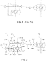
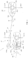
- Figures 2 and 3 show a driveline T according two respective variants of the disclosure.
- This driveline comprises an input IN and three outputs, two outputs OUT1, OUT2 being suitable to be connected to the axle shafts of the first axle A1 of the tandem and an output OUT3 being designed to transmit the torque to the second axle A2 with the respective outputs OUT 4 and OUT 5 to be connected to the wheels of the second axle.
- Both the first and the second axle comprise a respective differential DIF1 and DIF2 with a respective bevel gear CR1 and CR2 to transfer the rotary motion received from the respective pinions PG1 and PG2 to the organs of the differentials in a known manner. Therefore, rings and pinions define the same number of bevel gears.
- the input IN and the output OUT3 are parallel to one another, but not coaxial, and they are oriented according to a longitudinal extension of the vehicle, whereas the outputs OUT1 and OUT2 are perpendicular to the input IN1 and to the output OUT3.
- the second axle has an input shaft TX2 of its own having an accessible end IN2 and the outputs OUT4 and OUT5 perpendicular to the extension of the vehicle and to the direction defined by the input IN2.
- the output OUT3 and the input IN2 are interconnected by means of an outer transmission shaft TX, which is connected to the output OUT3 and to the input IN2 by means of the joints J1 and J2.
- IN indicates an accessible end of an auxiliary shaft AX, which is suitable to be connected, by means of a joint J, to the main driveline shaft MS of the vehicle, which, in turn, is driven by the engine E of the vehicle, which can be an internal combustion engine or a hybrid assembly.
- the main shaft MS clearly is directly connected to the auxiliary shaft, since there are no gears or clutches between them. This advantageously allows manufactures to minimize frictions and inertia when the second axle is not operating, as described hereinafter.
- the auxiliary shaft AX is associated with an intermediate shaft IA, which is parallel to the auxiliary shaft, but not coaxial thereto, by means of a motion transmission device DTM, which can be associated with the auxiliary shaft by means of a dog clutch CLA, which is mounted on the auxiliary shaft and can axially slide on it.
- a motion transmission device DTM which can be associated with the auxiliary shaft by means of a dog clutch CLA, which is mounted on the auxiliary shaft and can axially slide on it.
- the closing of the dog clutch CLA determines the rotary connection of the auxiliary shaft to the motion transmission device DTM, which, in turn, transmits the motion to the intermediate shaft IA.
- Said intermediate shaft IA has an accessible end, which defines the aforesaid third output OUT3.
- An actuator AT controls the opening and the closing of the dog clutch CLA.
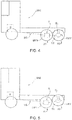
- the second axle A2 is associated with a lifting device SL, which allows the second axle A2 to be lifted, distancing the relative wheels from the ground, see the comparison of figures 4 and 5 .
- the lifting device SL is controlled in parallel with the dog clutch CLA; precisely, when the clutch is open, the second axle is lifted and, therefore, not operative and vice versa, when the clutch is closed, the axle is lowered and, hence, operative.
- the transmission device DTM comprises a first gear R1, which is mounted in the auxiliary shaft AX, and a second gear R2, which is fixed on the intermediate shaft IA so that the first gear operatively meshes on the second gear.
- the aforesaid dog clutch CLA determines the operative connection of the first gear with the auxiliary shaft AX and, therefore, the transmission of the motion to the differential DIF2 of the second axle A2 by means of the relative bevel gear PG2/CR2.
- the transmission device DTM comprises a further differential, which acts as a central differential between the first axle A1 and the second axle A2, as you can better see in the enlargement of figure 3a .
- the transmission device DTM is called "central differential" DFC.
- the symbols DFC and DTM are interchangeable.
- the gear ratio towards the first axle A1 is equal to the gear ratio towards the second axle A2, so that, when the second axle is operative, the two axles rotate at the same rotation speed regardless of the fact that they are indirectly interconnected by the ground.
- the auxiliary shaft is divided into two parts AX1 and AX2, which are coaxial to one another.
- AX1 on one side, is manufactured as one single piece together with the input IN and, on the opposite side, supports the satellite carrier of the central differential.
- Another planetary gear S1 opposes, in the central differential, the preceding planetary gear S2 and has a fulcrum that is integral to the casing of the differential and coaxial to the auxiliary shaft (AX1, AX2).
- the first gear Rl' is reversibly connectable in rotation to the box of the central differential by means of a second sliding clutch CLB, preferably a dog clutch, which is mounted on a part of the box of the differential having a cylindrical symmetry and provided with grooves and is suited to engage proper seats of the first gear R1'.
- CLB second sliding clutch
- the first gear Rl' operatively meshes n the second gear R2, etc..
- the actuator AT controls the two clutches in an opposite manner, so that, when a clutch is open, the other one is closed and vice versa.
- the central differential is locked because the first planetary gear S1 is built as one single piece together with the casing of the differential, whereas the second planetary gear S2, which is manufactured as one single piece together with the second part AX2 of the auxiliary shaft, is caused to be integral to the casing of the differential because of the first clutch CLA, which mutually locks said second part of the auxiliary shaft with the casing of the differential.
- the angular speed of the casing of the differential coincides with the angular speed of the first and second part of the auxiliary shaft.
- the first clutch is inactive, whereas the second clutch is active. Therefore, the differential has an input coinciding with the first part of the auxiliary shaft AX1 and two outputs represented by the two planetary gears S1 and S2, which, compared to the preceding operating mode, are not rigidly constrained to one another; hence, the planetary gear S2 represents the first output and the casing represents the second output of the central differential.
- the first gear Rl' is directly mounted on the casing of the central differential. This would lead you to think that the latter has a symmetry of rotation around the auxiliary shaft AX1, AX2. This situation is ideal because it minimizes the vibrations caused by the rotation of the casing. Nevertheless, the casing can have an axial symmetry relative to the auxiliary shaft AX (AX1 + AX2), but this symmetry does not necessarily have to be a rotation symmetry, as only one single portion thereof has a rotation symmetry, namely a cylindrical shape.
- Figure 4 shows an example of a vehicle VHE in a condition in which the second axle A2 is lowered and the torque is transferred from the engine E to the main driveline shaft MS to the driveline T, which transmits the motion of the right axle shaft OUT1 and to the left axle shaft OUT2, which define the first axle, and to the intermediate shaft IA, which delivers the motion, through the shaft TX and the joints J1 and J2, to the second axle and, precisely, to the input shaft TX2 of the second axle having a second end opposite the first accessible end IN2, on which there is steadily fixed the second pinion PG2 of the second bevel gear PG2/CR2, whose ring transfers the motion to the second differential DIF2 of the second axle A2.
- figure 5 shows a condition opposite the one of figure 4 , in which the same vehicle VHE has the second axle A2 lifted by means of a relative lifting device SL and the torque is transferred from the engine E to the main driveline shaft MS to the driveline T, which transmits the motion only to the first axle A1.
Landscapes
- Engineering & Computer Science (AREA)
- Mechanical Engineering (AREA)
- Chemical & Material Sciences (AREA)
- Combustion & Propulsion (AREA)
- Transportation (AREA)
- General Engineering & Computer Science (AREA)
- Arrangement And Driving Of Transmission Devices (AREA)
- Retarders (AREA)
- Traffic Control Systems (AREA)
Claims (6)
- Antriebsstrang von zwei Tandem-Antriebsachsen, der Folgendes umfasst:- eine erste Fahrzeugachse (A1) und eine zweite Fahrzeugachse (A2) parallel zu der ersten Achse (A1), die jeweils gegenüberliegende Enden besitzen, wovon jedes wenigstens ein Rad tragen kann und dafür ausgelegt ist, angehoben zu werden,- eine Hilfswelle (AX) mit einem ersten Ende und einem zweiten Ende gegenüber dem ersten Ende, wobei das erste Ende mit einem Eingang (IN) versehen ist, der durch eine Hauptantriebsstrangwelle (MS) direkt rotatorisch angetrieben wird, und wobei das zweite Ende der ersten Achse (A1) stabil zugeordnet ist, um sie rotatorisch anzutreiben,- eine Zwischenwelle (IA) mit einem ersten Ende und einem zweiten Ende gegenüber dem ersten Ende, wobei das zweite Ende der zweiten Achse (A2) stabil zugeordnet ist, um sie rotatorisch anzutreiben,- eine Kraftübertragungsvorrichtung (DTM), die mit der Hilfswelle (AX) lösbar verbunden werden kann, um eine Drehung von der Hilfswelle an die Zwischenwelle (IA) zu übertragen,- Betätigungsmittel (AT, SL), die konfiguriert sind, die zweite Achse abzusenken, wenn die Kraftübertragungsvorrichtung die Hilfswelle mit der Zwischenwelle betriebstechnisch verbindet und umgekehrt,- eine Hubeinrichtung (SL), die der zweiten Fahrzeugachse (A2) zugeordnet ist, um ein Anheben der zweiten Fahrzeugachse (A2) zuzulassen,dadurch gekennzeichnet, dass die Kraftübertragungsvorrichtung (DTM) Folgendes umfasst:- ein erstes Zahnrad (R1'), das der Hilfswelle zugeordnet ist, und- ein zweites Zahnrad, das an der Zwischenwelle (IA) betriebstechnisch befestigt ist, wobei das zweite Zahnrad mit dem ersten Zahnrad betriebstechnisch kämmt, undein Mittendifferential (DFC), das einen Eingang sowie einen ersten und einen zweiten Ausgang besitzt,
wobei die Hilfswelle (AX) einen ersten Abschnitt (AX1) und einen zweiten Abschnitt (AX2), die voneinander getrennt sind, aufweist, wobei der erste Abschnitt dem Eingang des Mittendifferentials zugeordnet ist und der zweite Abschnitt dem ersten Ausgang zugeordnet ist und wobei das erste Zahnrad (R1') dem zweiten Ausgang wahlweise zugeordnet werden kann und wobei der Ausgang und der zweite Ausgang wahlweise miteinander verriegelt werden können,
wobei die Betätigungsmittel eine erste Kupplung (CLA), die den ersten und den zweiten Ausgang miteinander verriegeln kann, und eine zweite Kupplung (CLB), die den zweiten Ausgang dem ersten Zahnrad (R1') wahlweise zuordnen kann, aufweisen, und
wobei die Betätigungsmittel so konfiguriert sind, dass bei ausgerückter zweiter Kupplung die erste Kupplung eingerückt ist und die Hubeinrichtung aktiviert wird und umgekehrt,
wobei das Mittendifferential (DFC) ein Gehäuse (CDH), das den zweiten Ausgang definiert, ein erstes Planetenrad (S1), dessen Drehachse mit dem Gehäuse einteilig ausgebildet ist und zu der Hilfswelle koaxial ist, ein zweites Planetenrad (S2) parallel zu dem ersten Planetenrad, das den ersten Ausgang definiert, einen Satellitenträger, dessen Drehachse mit dem ersten Abschnitt (AX1) der Hilfswelle zusammenfällt und der den Eingang definiert, und wenigstens einen Satelliten, der mit dem ersten und dem zweiten Planetenrad (S1, S2) kämmt, umfasst und
wobei die erste Kupplung (CLA) eine Kupplung des Klauentyps ist, die auf dem zweiten Abschnitt (AX2) der Hilfswelle axial gleitet und den zweiten Abschnitt (AX2) der Hilfswelle mit dem Gehäuse lösbar drehfest verbinden kann, und
wobei die zweite Kupplung vom Frontaltyp ist und auf einem Teil des Gehäuses axial gleitet und eine Zylindersymmetrie koaxial zu der Hilfswelle (AX1, AX2) aufweist und das Gehäuse mit dem ersten Zahnrad (R1') lösbar drehfest verbinden kann. - Antriebsstrang nach Anspruch 1, wobei die Betätigungsmittel eine Kupplung (CLA) umfassen, die eine betriebstechnische Verbindung zwischen der Hilfswelle und der Zwischenwelle mittels der Kraftübertragungsvorrichtung (DTM) und eines Aktors (AT), der der Kupplung betriebstechnisch zugeordnet ist, reversibel steuern kann.
- Antriebsstrang nach einem der Ansprüche 1 oder 2, wobei die Betätigungsmittel die Hubeinrichtung (SL) umfassen, die eine Drucklufthubeinrichtung ist, die die zweite Achse anheben kann und sie dabei vom Boden entfernt.
- Antriebsstrang nach einem der vorhergehenden Ansprüche, wobei das zweite Ende der Hilfswelle der ersten Achse (A1) über ein erstes Kegelrad (PG1/CR1) stabil zugeordnet ist und/oder wobei das zweite Ende der Zwischenwelle der zweiten Achse (A2) über ein zweites Kegelrad (PG2, CR2) stabil zugeordnet ist.
- Antriebsstrang nach einem der vorhergehenden Ansprüche, wobei das erste Kegelrad ein Ritzel, das dem zweiten Ende der Hilfswelle stabil zugeordnet ist, und einen Ring, der einem Differential (DIF1) der ersten Achse stabil zugeordnet ist, aufweist.
- Industrielles Fahrzeug, das eine erste (A1) und eine zweite (A2) Hinterachse, die als Tandem konfiguriert sind, eine Kraftmaschine (E), eine Hauptantriebsstrangwelle (MS), die mit einem Ausgang der Kraftmaschine verbunden ist, und einen Antriebsstrang (T) nach einem der vorhergehenden Ansprüche umfasst, wovon ein Eingang (IN) mit der Hauptantriebsstrangwelle (MS) betriebstechnisch verbunden ist.
Applications Claiming Priority (2)
| Application Number | Priority Date | Filing Date | Title |
|---|---|---|---|
| IT102016000119789A IT201600119789A1 (it) | 2016-11-25 | 2016-11-25 | Trasmissione di due assali traenti in tandem e veicolo comprendente detta trasmissione |
| PCT/IB2017/057393 WO2018096500A1 (en) | 2016-11-25 | 2017-11-24 | Driveline of two driving tandem axles and vehicle comprising said driveline |
Publications (2)
| Publication Number | Publication Date |
|---|---|
| EP3544841A1 EP3544841A1 (de) | 2019-10-02 |
| EP3544841B1 true EP3544841B1 (de) | 2021-06-02 |
Family
ID=58347795
Family Applications (1)
| Application Number | Title | Priority Date | Filing Date |
|---|---|---|---|
| EP17822450.7A Active EP3544841B1 (de) | 2016-11-25 | 2017-11-24 | Antriebsstrang von zwei tandemantriebsachsen und fahrzeug mit dem antriebsstrang |
Country Status (5)
| Country | Link |
|---|---|
| US (1) | US11007871B2 (de) |
| EP (1) | EP3544841B1 (de) |
| AU (1) | AU2017365114B2 (de) |
| IT (1) | IT201600119789A1 (de) |
| WO (1) | WO2018096500A1 (de) |
Families Citing this family (1)
| Publication number | Priority date | Publication date | Assignee | Title |
|---|---|---|---|---|
| CN114148139B (zh) * | 2021-11-09 | 2023-10-03 | 中国重汽集团济南动力有限公司 | 一种驱动桥可提升空气悬架控制系统 |
Family Cites Families (11)
| Publication number | Priority date | Publication date | Assignee | Title |
|---|---|---|---|---|
| US2742684A (en) * | 1952-09-23 | 1956-04-24 | Bill W Rising | Power divider |
| JPH08337125A (ja) * | 1995-06-13 | 1996-12-24 | Hino Motors Ltd | 駆動輪後二軸車に使用されるインタアクスル・ディファレンシャルおよび駆動システム |
| US7291083B2 (en) * | 2004-08-04 | 2007-11-06 | Arvinmeritor Technology, Llc | Inter-axle differential assembly |
| DE102006060842A1 (de) * | 2006-12-22 | 2008-06-26 | Daimler Ag | Tandemachse mit antreibbarer Liftachse |
| DE102007013258A1 (de) * | 2007-03-20 | 2008-09-25 | Daimler Ag | Tandemachse mit einer wahlweise zugeschalteten ersten Achse |
| CA2805163A1 (en) * | 2010-07-20 | 2012-01-26 | Dana Heavy Vehicle Systems Group, Llc | Drive axle system having a clutching device |
| US8398520B1 (en) * | 2011-09-30 | 2013-03-19 | Arvinmeritor Technology, Llc | Drive axle assembly and disengagement system |
| US8911321B2 (en) * | 2012-08-23 | 2014-12-16 | Dana Heavy Vehicle Systems Group, Llc | Tandem axle system |
| EP2928718B1 (de) * | 2012-12-05 | 2020-08-19 | Mack Trucks, Inc. | Fahrzeug mit mehreren antriebsachsen und einer heb- und senkbaren hinteren antriebsachse sowie verfahren zur neutralisierung der hinterantriebsachse und zum betreiben solch eines fahrzeugs |
| US9644726B2 (en) * | 2014-11-11 | 2017-05-09 | Dana Heavy Vehicle Systems Group, Llc | Vehicle differential and method of operating the same |
| DE102017218089A1 (de) * | 2017-10-11 | 2019-04-11 | Zf Friedrichshafen Ag | Tandemachse |
-
2016
- 2016-11-25 IT IT102016000119789A patent/IT201600119789A1/it unknown
-
2017
- 2017-11-24 EP EP17822450.7A patent/EP3544841B1/de active Active
- 2017-11-24 WO PCT/IB2017/057393 patent/WO2018096500A1/en not_active Ceased
- 2017-11-24 AU AU2017365114A patent/AU2017365114B2/en active Active
- 2017-11-24 US US16/462,822 patent/US11007871B2/en active Active
Non-Patent Citations (1)
| Title |
|---|
| None * |
Also Published As
| Publication number | Publication date |
|---|---|
| AU2017365114A1 (en) | 2019-05-30 |
| US11007871B2 (en) | 2021-05-18 |
| AU2017365114B2 (en) | 2022-12-22 |
| IT201600119789A1 (it) | 2018-05-25 |
| EP3544841A1 (de) | 2019-10-02 |
| US20190299775A1 (en) | 2019-10-03 |
| BR112019010642A2 (pt) | 2019-10-01 |
| WO2018096500A1 (en) | 2018-05-31 |
Similar Documents
| Publication | Publication Date | Title |
|---|---|---|
| US9784355B1 (en) | Axle disconnect and differential lock combination | |
| CN103889763B (zh) | 用于串列驱动桥车辆的具有可反转桥间差速器的前载架组件、用于串列驱动桥车辆的动力传动系以及串列驱动桥车辆 | |
| US11168743B2 (en) | Shift isolation lever system for power-actuated coupling device | |
| US9074672B2 (en) | Disconnectable driveline for all-wheel drive vehicle | |
| EP1072457B1 (de) | Getriebeeinheit bestehend aus schrägverzahnten Umlaufgetriebesätzen | |
| US9791031B2 (en) | Differential having compact bevel cross shaft retention using case bolts and adjacent shafts | |
| US10330164B2 (en) | Coupling assembly and driveline assembly | |
| CN110857728B (zh) | 具有带有双断开式差速器的车辆传动系部件的车辆传动系 | |
| US20160138695A1 (en) | Disconnecting awd driveline with torque-vectoring capabilities | |
| US20180209527A1 (en) | Drive unit with torque vectoring and an axle disconnect and reconnect mechanism | |
| US20140335992A1 (en) | Rotary power transfer disconnect device | |
| CN102369373A (zh) | 传动组件 | |
| US20180345785A1 (en) | Driveline rapid disconnect apparatus | |
| CN109311393B (zh) | 轴间差速组件,驱动轴组件和机动车辆 | |
| US10876613B2 (en) | Differential gear for a motor vehicle | |
| EP3544841B1 (de) | Antriebsstrang von zwei tandemantriebsachsen und fahrzeug mit dem antriebsstrang | |
| US6931964B2 (en) | Transfer case with multi-gear transfer mechanism | |
| KR102537272B1 (ko) | 차동 제한 장치를 위한 비동기식 기어 맞물림 이벤트 | |
| US9656545B2 (en) | Tandem axle disconnect with synchronized overdrive | |
| US11230188B2 (en) | Hydraulically actuated transfer case | |
| WO2026038977A1 (en) | Differential device with disconnect | |
| CN114321329A (zh) | 用于车辆动力传输单元的换挡机构 |
Legal Events
| Date | Code | Title | Description |
|---|---|---|---|
| STAA | Information on the status of an ep patent application or granted ep patent |
Free format text: STATUS: UNKNOWN |
|
| STAA | Information on the status of an ep patent application or granted ep patent |
Free format text: STATUS: THE INTERNATIONAL PUBLICATION HAS BEEN MADE |
|
| PUAI | Public reference made under article 153(3) epc to a published international application that has entered the european phase |
Free format text: ORIGINAL CODE: 0009012 |
|
| STAA | Information on the status of an ep patent application or granted ep patent |
Free format text: STATUS: REQUEST FOR EXAMINATION WAS MADE |
|
| 17P | Request for examination filed |
Effective date: 20190509 |
|
| AK | Designated contracting states |
Kind code of ref document: A1 Designated state(s): AL AT BE BG CH CY CZ DE DK EE ES FI FR GB GR HR HU IE IS IT LI LT LU LV MC MK MT NL NO PL PT RO RS SE SI SK SM TR |
|
| AX | Request for extension of the european patent |
Extension state: BA ME |
|
| DAV | Request for validation of the european patent (deleted) | ||
| DAX | Request for extension of the european patent (deleted) | ||
| STAA | Information on the status of an ep patent application or granted ep patent |
Free format text: STATUS: EXAMINATION IS IN PROGRESS |
|
| 17Q | First examination report despatched |
Effective date: 20200414 |
|
| GRAP | Despatch of communication of intention to grant a patent |
Free format text: ORIGINAL CODE: EPIDOSNIGR1 |
|
| STAA | Information on the status of an ep patent application or granted ep patent |
Free format text: STATUS: GRANT OF PATENT IS INTENDED |
|
| INTG | Intention to grant announced |
Effective date: 20201007 |
|
| GRAJ | Information related to disapproval of communication of intention to grant by the applicant or resumption of examination proceedings by the epo deleted |
Free format text: ORIGINAL CODE: EPIDOSDIGR1 |
|
| STAA | Information on the status of an ep patent application or granted ep patent |
Free format text: STATUS: EXAMINATION IS IN PROGRESS |
|
| INTC | Intention to grant announced (deleted) | ||
| GRAP | Despatch of communication of intention to grant a patent |
Free format text: ORIGINAL CODE: EPIDOSNIGR1 |
|
| GRAJ | Information related to disapproval of communication of intention to grant by the applicant or resumption of examination proceedings by the epo deleted |
Free format text: ORIGINAL CODE: EPIDOSDIGR1 |
|
| GRAP | Despatch of communication of intention to grant a patent |
Free format text: ORIGINAL CODE: EPIDOSNIGR1 |
|
| STAA | Information on the status of an ep patent application or granted ep patent |
Free format text: STATUS: GRANT OF PATENT IS INTENDED |
|
| GRAS | Grant fee paid |
Free format text: ORIGINAL CODE: EPIDOSNIGR3 |
|
| GRAA | (expected) grant |
Free format text: ORIGINAL CODE: 0009210 |
|
| STAA | Information on the status of an ep patent application or granted ep patent |
Free format text: STATUS: THE PATENT HAS BEEN GRANTED |
|
| INTG | Intention to grant announced |
Effective date: 20210414 |
|
| REG | Reference to a national code |
Ref country code: CH Ref legal event code: EP |
|
| AK | Designated contracting states |
Kind code of ref document: B1 Designated state(s): AL AT BE BG CH CY CZ DE DK EE ES FI FR GB GR HR HU IE IS IT LI LT LU LV MC MK MT NL NO PL PT RO RS SE SI SK SM TR |
|
| REG | Reference to a national code |
Ref country code: GB Ref legal event code: FG4D |
|
| REG | Reference to a national code |
Ref country code: AT Ref legal event code: REF Ref document number: 1398122 Country of ref document: AT Kind code of ref document: T Effective date: 20210615 |
|
| REG | Reference to a national code |
Ref country code: IE Ref legal event code: FG4D |
|
| REG | Reference to a national code |
Ref country code: DE Ref legal event code: R096 Ref document number: 602017039795 Country of ref document: DE |
|
| REG | Reference to a national code |
Ref country code: LT Ref legal event code: MG9D |
|
| PG25 | Lapsed in a contracting state [announced via postgrant information from national office to epo] |
Ref country code: LT Free format text: LAPSE BECAUSE OF FAILURE TO SUBMIT A TRANSLATION OF THE DESCRIPTION OR TO PAY THE FEE WITHIN THE PRESCRIBED TIME-LIMIT Effective date: 20210602 Ref country code: FI Free format text: LAPSE BECAUSE OF FAILURE TO SUBMIT A TRANSLATION OF THE DESCRIPTION OR TO PAY THE FEE WITHIN THE PRESCRIBED TIME-LIMIT Effective date: 20210602 Ref country code: BG Free format text: LAPSE BECAUSE OF FAILURE TO SUBMIT A TRANSLATION OF THE DESCRIPTION OR TO PAY THE FEE WITHIN THE PRESCRIBED TIME-LIMIT Effective date: 20210902 Ref country code: HR Free format text: LAPSE BECAUSE OF FAILURE TO SUBMIT A TRANSLATION OF THE DESCRIPTION OR TO PAY THE FEE WITHIN THE PRESCRIBED TIME-LIMIT Effective date: 20210602 |
|
| REG | Reference to a national code |
Ref country code: NL Ref legal event code: MP Effective date: 20210602 |
|
| REG | Reference to a national code |
Ref country code: AT Ref legal event code: MK05 Ref document number: 1398122 Country of ref document: AT Kind code of ref document: T Effective date: 20210602 |
|
| PG25 | Lapsed in a contracting state [announced via postgrant information from national office to epo] |
Ref country code: GR Free format text: LAPSE BECAUSE OF FAILURE TO SUBMIT A TRANSLATION OF THE DESCRIPTION OR TO PAY THE FEE WITHIN THE PRESCRIBED TIME-LIMIT Effective date: 20210903 Ref country code: PL Free format text: LAPSE BECAUSE OF FAILURE TO SUBMIT A TRANSLATION OF THE DESCRIPTION OR TO PAY THE FEE WITHIN THE PRESCRIBED TIME-LIMIT Effective date: 20210602 Ref country code: NO Free format text: LAPSE BECAUSE OF FAILURE TO SUBMIT A TRANSLATION OF THE DESCRIPTION OR TO PAY THE FEE WITHIN THE PRESCRIBED TIME-LIMIT Effective date: 20210902 Ref country code: LV Free format text: LAPSE BECAUSE OF FAILURE TO SUBMIT A TRANSLATION OF THE DESCRIPTION OR TO PAY THE FEE WITHIN THE PRESCRIBED TIME-LIMIT Effective date: 20210602 Ref country code: RS Free format text: LAPSE BECAUSE OF FAILURE TO SUBMIT A TRANSLATION OF THE DESCRIPTION OR TO PAY THE FEE WITHIN THE PRESCRIBED TIME-LIMIT Effective date: 20210602 Ref country code: SE Free format text: LAPSE BECAUSE OF FAILURE TO SUBMIT A TRANSLATION OF THE DESCRIPTION OR TO PAY THE FEE WITHIN THE PRESCRIBED TIME-LIMIT Effective date: 20210602 |
|
| PG25 | Lapsed in a contracting state [announced via postgrant information from national office to epo] |
Ref country code: SK Free format text: LAPSE BECAUSE OF FAILURE TO SUBMIT A TRANSLATION OF THE DESCRIPTION OR TO PAY THE FEE WITHIN THE PRESCRIBED TIME-LIMIT Effective date: 20210602 Ref country code: SM Free format text: LAPSE BECAUSE OF FAILURE TO SUBMIT A TRANSLATION OF THE DESCRIPTION OR TO PAY THE FEE WITHIN THE PRESCRIBED TIME-LIMIT Effective date: 20210602 Ref country code: ES Free format text: LAPSE BECAUSE OF FAILURE TO SUBMIT A TRANSLATION OF THE DESCRIPTION OR TO PAY THE FEE WITHIN THE PRESCRIBED TIME-LIMIT Effective date: 20210602 Ref country code: RO Free format text: LAPSE BECAUSE OF FAILURE TO SUBMIT A TRANSLATION OF THE DESCRIPTION OR TO PAY THE FEE WITHIN THE PRESCRIBED TIME-LIMIT Effective date: 20210602 Ref country code: PT Free format text: LAPSE BECAUSE OF FAILURE TO SUBMIT A TRANSLATION OF THE DESCRIPTION OR TO PAY THE FEE WITHIN THE PRESCRIBED TIME-LIMIT Effective date: 20211004 Ref country code: NL Free format text: LAPSE BECAUSE OF FAILURE TO SUBMIT A TRANSLATION OF THE DESCRIPTION OR TO PAY THE FEE WITHIN THE PRESCRIBED TIME-LIMIT Effective date: 20210602 Ref country code: AT Free format text: LAPSE BECAUSE OF FAILURE TO SUBMIT A TRANSLATION OF THE DESCRIPTION OR TO PAY THE FEE WITHIN THE PRESCRIBED TIME-LIMIT Effective date: 20210602 Ref country code: CZ Free format text: LAPSE BECAUSE OF FAILURE TO SUBMIT A TRANSLATION OF THE DESCRIPTION OR TO PAY THE FEE WITHIN THE PRESCRIBED TIME-LIMIT Effective date: 20210602 Ref country code: EE Free format text: LAPSE BECAUSE OF FAILURE TO SUBMIT A TRANSLATION OF THE DESCRIPTION OR TO PAY THE FEE WITHIN THE PRESCRIBED TIME-LIMIT Effective date: 20210602 |
|
| REG | Reference to a national code |
Ref country code: DE Ref legal event code: R097 Ref document number: 602017039795 Country of ref document: DE |
|
| PLBE | No opposition filed within time limit |
Free format text: ORIGINAL CODE: 0009261 |
|
| STAA | Information on the status of an ep patent application or granted ep patent |
Free format text: STATUS: NO OPPOSITION FILED WITHIN TIME LIMIT |
|
| PG25 | Lapsed in a contracting state [announced via postgrant information from national office to epo] |
Ref country code: DK Free format text: LAPSE BECAUSE OF FAILURE TO SUBMIT A TRANSLATION OF THE DESCRIPTION OR TO PAY THE FEE WITHIN THE PRESCRIBED TIME-LIMIT Effective date: 20210602 |
|
| 26N | No opposition filed |
Effective date: 20220303 |
|
| PG25 | Lapsed in a contracting state [announced via postgrant information from national office to epo] |
Ref country code: AL Free format text: LAPSE BECAUSE OF FAILURE TO SUBMIT A TRANSLATION OF THE DESCRIPTION OR TO PAY THE FEE WITHIN THE PRESCRIBED TIME-LIMIT Effective date: 20210602 |
|
| PG25 | Lapsed in a contracting state [announced via postgrant information from national office to epo] |
Ref country code: MC Free format text: LAPSE BECAUSE OF FAILURE TO SUBMIT A TRANSLATION OF THE DESCRIPTION OR TO PAY THE FEE WITHIN THE PRESCRIBED TIME-LIMIT Effective date: 20210602 |
|
| REG | Reference to a national code |
Ref country code: CH Ref legal event code: PL |
|
| PG25 | Lapsed in a contracting state [announced via postgrant information from national office to epo] |
Ref country code: LU Free format text: LAPSE BECAUSE OF NON-PAYMENT OF DUE FEES Effective date: 20211124 Ref country code: BE Free format text: LAPSE BECAUSE OF NON-PAYMENT OF DUE FEES Effective date: 20211130 |
|
| REG | Reference to a national code |
Ref country code: BE Ref legal event code: MM Effective date: 20211130 |
|
| PG25 | Lapsed in a contracting state [announced via postgrant information from national office to epo] |
Ref country code: LI Free format text: LAPSE BECAUSE OF NON-PAYMENT OF DUE FEES Effective date: 20211130 Ref country code: CH Free format text: LAPSE BECAUSE OF NON-PAYMENT OF DUE FEES Effective date: 20211130 |
|
| PG25 | Lapsed in a contracting state [announced via postgrant information from national office to epo] |
Ref country code: IE Free format text: LAPSE BECAUSE OF NON-PAYMENT OF DUE FEES Effective date: 20211124 |
|
| P01 | Opt-out of the competence of the unified patent court (upc) registered |
Effective date: 20230519 |
|
| PG25 | Lapsed in a contracting state [announced via postgrant information from national office to epo] |
Ref country code: CY Free format text: LAPSE BECAUSE OF FAILURE TO SUBMIT A TRANSLATION OF THE DESCRIPTION OR TO PAY THE FEE WITHIN THE PRESCRIBED TIME-LIMIT Effective date: 20210602 |
|
| PG25 | Lapsed in a contracting state [announced via postgrant information from national office to epo] |
Ref country code: HU Free format text: LAPSE BECAUSE OF FAILURE TO SUBMIT A TRANSLATION OF THE DESCRIPTION OR TO PAY THE FEE WITHIN THE PRESCRIBED TIME-LIMIT; INVALID AB INITIO Effective date: 20171124 |
|
| PG25 | Lapsed in a contracting state [announced via postgrant information from national office to epo] |
Ref country code: MK Free format text: LAPSE BECAUSE OF FAILURE TO SUBMIT A TRANSLATION OF THE DESCRIPTION OR TO PAY THE FEE WITHIN THE PRESCRIBED TIME-LIMIT Effective date: 20210602 |
|
| PG25 | Lapsed in a contracting state [announced via postgrant information from national office to epo] |
Ref country code: MT Free format text: LAPSE BECAUSE OF FAILURE TO SUBMIT A TRANSLATION OF THE DESCRIPTION OR TO PAY THE FEE WITHIN THE PRESCRIBED TIME-LIMIT Effective date: 20210602 |
|
| PG25 | Lapsed in a contracting state [announced via postgrant information from national office to epo] |
Ref country code: TR Free format text: LAPSE BECAUSE OF FAILURE TO SUBMIT A TRANSLATION OF THE DESCRIPTION OR TO PAY THE FEE WITHIN THE PRESCRIBED TIME-LIMIT Effective date: 20210602 |
|
| PGFP | Annual fee paid to national office [announced via postgrant information from national office to epo] |
Ref country code: DE Payment date: 20251126 Year of fee payment: 9 |
|
| PGFP | Annual fee paid to national office [announced via postgrant information from national office to epo] |
Ref country code: GB Payment date: 20251125 Year of fee payment: 9 |
|
| PGFP | Annual fee paid to national office [announced via postgrant information from national office to epo] |
Ref country code: IT Payment date: 20251110 Year of fee payment: 9 |
|
| PGFP | Annual fee paid to national office [announced via postgrant information from national office to epo] |
Ref country code: FR Payment date: 20251124 Year of fee payment: 9 |