EP3544703B1 - Zahnschutzvorrichtung und verfahren zu ihrer herstellung - Google Patents
Zahnschutzvorrichtung und verfahren zu ihrer herstellung Download PDFInfo
- Publication number
- EP3544703B1 EP3544703B1 EP18700837.0A EP18700837A EP3544703B1 EP 3544703 B1 EP3544703 B1 EP 3544703B1 EP 18700837 A EP18700837 A EP 18700837A EP 3544703 B1 EP3544703 B1 EP 3544703B1
- Authority
- EP
- European Patent Office
- Prior art keywords
- insert
- deep
- film
- plastic
- teeth
- Prior art date
- Legal status (The legal status is an assumption and is not a legal conclusion. Google has not performed a legal analysis and makes no representation as to the accuracy of the status listed.)
- Active
Links
Images


Classifications
-
- A—HUMAN NECESSITIES
- A63—SPORTS; GAMES; AMUSEMENTS
- A63B—APPARATUS FOR PHYSICAL TRAINING, GYMNASTICS, SWIMMING, CLIMBING, OR FENCING; BALL GAMES; TRAINING EQUIPMENT
- A63B71/00—Games or sports accessories not covered in groups A63B1/00 - A63B69/00
- A63B71/08—Body-protectors for players or sportsmen, i.e. body-protecting accessories affording protection of body parts against blows or collisions
- A63B71/085—Mouth or teeth protectors
-
- A—HUMAN NECESSITIES
- A63—SPORTS; GAMES; AMUSEMENTS
- A63B—APPARATUS FOR PHYSICAL TRAINING, GYMNASTICS, SWIMMING, CLIMBING, OR FENCING; BALL GAMES; TRAINING EQUIPMENT
- A63B69/00—Training appliances or apparatus for special sports
- A63B69/0024—Training appliances or apparatus for special sports for hockey
-
- B—PERFORMING OPERATIONS; TRANSPORTING
- B29—WORKING OF PLASTICS; WORKING OF SUBSTANCES IN A PLASTIC STATE IN GENERAL
- B29C—SHAPING OR JOINING OF PLASTICS; SHAPING OF MATERIAL IN A PLASTIC STATE, NOT OTHERWISE PROVIDED FOR; AFTER-TREATMENT OF THE SHAPED PRODUCTS, e.g. REPAIRING
- B29C64/00—Additive manufacturing, i.e. manufacturing of three-dimensional [3D] objects by additive deposition, additive agglomeration or additive layering, e.g. by 3D printing, stereolithography or selective laser sintering
- B29C64/10—Processes of additive manufacturing
-
- B—PERFORMING OPERATIONS; TRANSPORTING
- B29—WORKING OF PLASTICS; WORKING OF SUBSTANCES IN A PLASTIC STATE IN GENERAL
- B29C—SHAPING OR JOINING OF PLASTICS; SHAPING OF MATERIAL IN A PLASTIC STATE, NOT OTHERWISE PROVIDED FOR; AFTER-TREATMENT OF THE SHAPED PRODUCTS, e.g. REPAIRING
- B29C64/00—Additive manufacturing, i.e. manufacturing of three-dimensional [3D] objects by additive deposition, additive agglomeration or additive layering, e.g. by 3D printing, stereolithography or selective laser sintering
- B29C64/30—Auxiliary operations or equipment
- B29C64/364—Conditioning of environment
-
- B—PERFORMING OPERATIONS; TRANSPORTING
- B29—WORKING OF PLASTICS; WORKING OF SUBSTANCES IN A PLASTIC STATE IN GENERAL
- B29C—SHAPING OR JOINING OF PLASTICS; SHAPING OF MATERIAL IN A PLASTIC STATE, NOT OTHERWISE PROVIDED FOR; AFTER-TREATMENT OF THE SHAPED PRODUCTS, e.g. REPAIRING
- B29C64/00—Additive manufacturing, i.e. manufacturing of three-dimensional [3D] objects by additive deposition, additive agglomeration or additive layering, e.g. by 3D printing, stereolithography or selective laser sintering
- B29C64/30—Auxiliary operations or equipment
- B29C64/386—Data acquisition or data processing for additive manufacturing
-
- B—PERFORMING OPERATIONS; TRANSPORTING
- B29—WORKING OF PLASTICS; WORKING OF SUBSTANCES IN A PLASTIC STATE IN GENERAL
- B29C—SHAPING OR JOINING OF PLASTICS; SHAPING OF MATERIAL IN A PLASTIC STATE, NOT OTHERWISE PROVIDED FOR; AFTER-TREATMENT OF THE SHAPED PRODUCTS, e.g. REPAIRING
- B29C64/00—Additive manufacturing, i.e. manufacturing of three-dimensional [3D] objects by additive deposition, additive agglomeration or additive layering, e.g. by 3D printing, stereolithography or selective laser sintering
- B29C64/40—Structures for supporting 3D objects during manufacture and intended to be sacrificed after completion thereof
-
- B—PERFORMING OPERATIONS; TRANSPORTING
- B33—ADDITIVE MANUFACTURING TECHNOLOGY
- B33Y—ADDITIVE MANUFACTURING, i.e. MANUFACTURING OF THREE-DIMENSIONAL [3D] OBJECTS BY ADDITIVE DEPOSITION, ADDITIVE AGGLOMERATION OR ADDITIVE LAYERING, e.g. BY 3D PRINTING, STEREOLITHOGRAPHY OR SELECTIVE LASER SINTERING
- B33Y10/00—Processes of additive manufacturing
-
- B—PERFORMING OPERATIONS; TRANSPORTING
- B33—ADDITIVE MANUFACTURING TECHNOLOGY
- B33Y—ADDITIVE MANUFACTURING, i.e. MANUFACTURING OF THREE-DIMENSIONAL [3D] OBJECTS BY ADDITIVE DEPOSITION, ADDITIVE AGGLOMERATION OR ADDITIVE LAYERING, e.g. BY 3D PRINTING, STEREOLITHOGRAPHY OR SELECTIVE LASER SINTERING
- B33Y40/00—Auxiliary operations or equipment, e.g. for material handling
-
- B—PERFORMING OPERATIONS; TRANSPORTING
- B33—ADDITIVE MANUFACTURING TECHNOLOGY
- B33Y—ADDITIVE MANUFACTURING, i.e. MANUFACTURING OF THREE-DIMENSIONAL [3D] OBJECTS BY ADDITIVE DEPOSITION, ADDITIVE AGGLOMERATION OR ADDITIVE LAYERING, e.g. BY 3D PRINTING, STEREOLITHOGRAPHY OR SELECTIVE LASER SINTERING
- B33Y50/00—Data acquisition or data processing for additive manufacturing
-
- B—PERFORMING OPERATIONS; TRANSPORTING
- B33—ADDITIVE MANUFACTURING TECHNOLOGY
- B33Y—ADDITIVE MANUFACTURING, i.e. MANUFACTURING OF THREE-DIMENSIONAL [3D] OBJECTS BY ADDITIVE DEPOSITION, ADDITIVE AGGLOMERATION OR ADDITIVE LAYERING, e.g. BY 3D PRINTING, STEREOLITHOGRAPHY OR SELECTIVE LASER SINTERING
- B33Y80/00—Products made by additive manufacturing
-
- A—HUMAN NECESSITIES
- A63—SPORTS; GAMES; AMUSEMENTS
- A63B—APPARATUS FOR PHYSICAL TRAINING, GYMNASTICS, SWIMMING, CLIMBING, OR FENCING; BALL GAMES; TRAINING EQUIPMENT
- A63B2209/00—Characteristics of used materials
-
- B—PERFORMING OPERATIONS; TRANSPORTING
- B29—WORKING OF PLASTICS; WORKING OF SUBSTANCES IN A PLASTIC STATE IN GENERAL
- B29K—INDEXING SCHEME ASSOCIATED WITH SUBCLASSES B29B, B29C OR B29D, RELATING TO MOULDING MATERIALS OR TO MATERIALS FOR MOULDS, REINFORCEMENTS, FILLERS OR PREFORMED PARTS, e.g. INSERTS
- B29K2101/00—Use of unspecified macromolecular compounds as moulding material
- B29K2101/12—Thermoplastic materials
Definitions
- the invention relates to a tooth protection device, consisting of a cross-section adapted to a toothed jaw of a user, approximately U-shaped or channel-shaped rail made of deep-drawable plastic, preferably made of ethylene vinyl acetate (EVA), the rail having two plastic films laminated on top of one another with an insert in between is primarily provided in a central front area facing away from the palate of the user and has a lateral extent that corresponds to several teeth of the user and has a width that corresponds to a dimension from a somewhat covered tooth tip area to the gums, as well as a method for producing a tooth protection device.
- EVA ethylene vinyl acetate
- Dental protection devices of the type indicated are known in the prior art. To date, such tooth protection devices have been manufactured as deep-drawn parts.
- a hollow shape of a toothed jaw of a corresponding patient was first formed with the aid of an impression with the aid of an impression compound. This hollow form was then used to fill it with a pourable, hardenable mass, so that a Model of the dentate jaw was available.
- a first deep-drawing film was then placed on this model, heated and molded onto the model, preferably by means of vacuum or also by means of overpressure, so that the contours of the toothed jaw were formed.
- the conventional design was only suitable for providing dental protection devices that were very limited in terms of their shape, layer thickness, flexibility and the like, because both the layer thickness of the insert part could not be set differently, but also because of the relative hardness of the material of the insert only smaller areas of the jaw to be protected are equipped with a corresponding insert in the case of the dental protection device could, for example, only the area of three teeth to the right and left of the center of the jaw.
- tooth protection devices are used particularly frequently to protect athletes, the tooth protection device with the insert located therein serving to distribute the force of blows and bumps over a larger area.
- Different types of sport cause different injury patterns.
- the bat hits a very small area with very high force, in contrast to boxing, in which the large, padded glove hits a large area. Therefore, in order to guarantee a perfect protective effect, the dental protection devices have to be adapted to the sport. This is only inadequately possible with conventional technology.
- foils with a layer thickness of 3 mm are usually used. These deep-drawn films are relatively elastic films that are very comfortable to wear. The inserts are usually harder and therefore much more difficult to incorporate in the deep-drawing process.
- the conventional insoles can only be used in a limited area of the jaw, preferably in the front area of three teeth to the right and left of the center.
- a bigger one Expansion of the mouthguard is hardly possible and not common because corresponding deformations are difficult to achieve by deep drawing for larger inserts.
- a tooth protection device which has an insert in the form of a film-like layer, the film being printed with a graphic.
- This tooth protection device made of D1 is manufactured using the deep-drawing process.
- the FR 2 576 798 A1 discloses a dental protection device consisting of several foils, the insert being formed by a rigid foil which is arranged between two flexible foils. The foils are heated in a known manner and molded onto a model by means of overpressure.
- the invention is based on the object of creating a tooth protection device of the generic type and also a method for the production thereof, whereby a better protective effect is to be achieved, a better adaptation to different types of sport is to be achieved and better protection of the toothed one
- the insert is a 3-D molded part made of light- or laser-curing plastic produced by means of a 3-D printer, the The layer thickness of the molded part varies, and that the insert has a lateral extension that corresponds more to a width of six teeth, preferably up to 10 teeth, very preferably the total length of a toothed jaw of a user, and that the layer thickness of the insert is between 0.5 mm and 5 mm.
- the insert is produced by means of a 3-D printer, so that a 3-D molded part made of light-curing or laser-curing plastic is thereby made available.
- This insert can be inserted between the deep-drawable plastic films and the forming process can be carried out recessively, whereby it is not necessary to further process the molded part produced by means of the 3-D printer by means of deep-drawing, but this part is in its originally produced form , Size, dimension and thickness introduced and after reshaping the first deep-drawable Plastic film is applied to this film on the model and positioned in the correct position, the second thermoformable film then being applied and thermoformed so that the complete tooth protection device is then made available.
- Ethylene vinyl acetate copolymer films are preferably used as deep-drawable films.
- the insert which is a molded part produced by means of the 3-D printer, can be adapted very easily to the respective application by varying the layer thickness of the molded part. In principle, there are no dimensional restrictions because the molded part does not need to be reshaped by deep drawing, as is customary in the prior art.
- the formation of the inlay in the form of a 3-D printed part makes it possible to extend it laterally up to practically the entire jaw to be protected.
- the height of the insert can extend up to the tips of the teeth or also beyond these tips, in which case a corresponding angled or rounded shape is to be provided. All of this can be easily implemented using a 3-D printing process.
- the layer thickness is varied and provided depending on the type of sport practiced. Since the insert does not have to be reshaped again by the deep-drawing process, a relatively thick design of up to 5 mm is possible. It is particularly preferably provided that the insert is a molded part made from acrylates, methacrylates, epoxides, vinyl ethers, vinyl esters, styrene derivatives, thiol-ene systems or mixtures thereof.
- Such materials are light-curing or laser-curing plastics, from which individual molded parts for tooth protection devices can be produced in a generative process.
- the molded part contains dyes.
- the light-curing plastics preferably processed above can contain dyes and other initiators, so that different product generations can be identified by using different colors.
- the insert consists of material with different hardnesses.
- the insert produced by means of 3-D printing can easily have different degrees of hardness, as this corresponds to the stress.
- the degrees of hardness can be varied in a single insert in order to provide a particularly excellent product.
- the insert consists of a material with a hardness of between 35 and 90 Shore A.
- the plastic films are at least partially opaque.
- the insert part is concealed or partially or completely invisible.
- the insert has cavities, depressions and / or perforations.
- This configuration makes it possible to design a tooth protection device in a special way. So it is possible through cavities, depressions or holes To achieve weight loss.
- the mechanical elasticity of the insert can also be influenced in a certain way by such configurations.
- the insert can also have such designs, for example in the form of lattice structures.
- the cavities, depressions and / or perforations are not filled by the material of the plastic films.
- the corresponding configuration ensures that the cavities or the like are retained even when the further plastic films are applied by deep drawing, so that the functions desired by the corresponding designs are maintained even when the further plastic films are applied.
- Such a configuration can be helpful, for example, for better shock absorption.
- the insert is protruded on all sides by the plastic films and the plastic films lie directly on top of one another in the protruding area and are laminated on one another.
- Such a configuration ensures that mechanical retentions can be dispensed with, since a firm mechanical hold is created and a change in position can be excluded.
- the insert is protruded on all sides by the plastic film.
- plastic films are (only) connected directly to one another in the protruding areas so that they are cohesive and secure the position.
- the insert preferably has at least one predetermined breaking point transversely to its longitudinal extension.
- Such dental protection devices can have predetermined breaking points so that different possible injury patterns can be taken into account during certain uses, that is to say certain types of sport. Whether and to what extent and at what point such a design of predetermined breaking points makes sense must be decided on a case-by-case basis. What is essential is the fact that such predetermined breaking points can be introduced in a simple manner during the production of the molded part using a 3-D printer.
- the insert consists of radio-opaque material, in particular is X-ray opaque.
- the radio-opaque material can be, for example, a lead rubber material which, due to its structure, is x-ray opaque in contrast to the deep-drawing foils used, that is to say is visible on an x-ray image. If an athlete undesirably aspirates such a mouthguard, that is to say swallowed it in extreme cases, the position of the mouthguard in the body of the user can be made visible in a simple way in order to carry out an emergency operation.
- first plastic film to be adjacent to the toothed jaw has a contouring adapted to the shape of the jaw including the teeth, that the insert on the side facing the first plastic film has the same contouring on this adjacent side, and that the second has the same contouring the inlay applied plastic film on its side resting on this inlay and on the protruding part over the first plastic film on this adjacent area following the shape of the outside of the inlay and the contact surface of the first plastic film.
- the application of the second plastic film also leads to an exact adaptation to the insert, so that overall both a secure fit and excellent position retention of the parts in relation to one another is achieved in the final state.
- the plastic films are firmly connected to one another in the areas in which they lie directly on top of one another and the molded part is positioned between the plastic films, but is kept slightly movable without being bonded to them.
- the invention also relates to a method for producing a tooth protection device, in particular according to one of claims 1 to 15, wherein a hollow form of a toothed jaw is formed by means of an impression with the aid of an impression compound, the hollow form is filled with a pourable, hardenable compound and thus a model of the toothed jaw is made, which is preferably hardened, in particular light-hardened, a first deep-drawing film is placed on the model, heated and by means of Vacuum or overpressure is applied to the model so that the contours of the dentate jaw are formed.
- the shape data in the area to which an insert is to be applied is tapped from the surface of the first deep-drawing film formed in this way, which is still held by the model, and stored in a data logger / -memory are stored, by means of the data retrieved from the data memory and with the addition of the data essential for the insert, such as material thickness, a 3-D molded part is generated by means of a printer by means of a generative process, the 3-D molded part manufactured in this way as Insert is applied to the deep-drawn first deep-drawing film located on the model, then the second deep-drawing film is placed on the insert and the area of the first deep-drawing film protruding beyond the insert in every direction, heated and molded using vacuum or overpressure, then preferably cooling is carried out and then the finished mouthguard device is removed from the model, with the insert having a lateral extension that corresponds to more than a width of six teeth, preferably up to 10 teeth, most
- a hollow form of a toothed jaw is first produced by means of an impression and with the aid of an impression compound.
- This hollow form is then used to produce a model of the dentate jaw used.
- the first deep-drawing film is then placed on this model, heated and, preferably by means of a vacuum, molded onto the model so that its contours are depicted.
- the shape of the area of the first deep-drawing film formed in this way, which is still held by the model, is recorded, for example, by a scanner, and the shape data is picked up, especially in the area to which an insert is to be applied, and transferred and stored in a data logger memory.
- 3-D molded parts can be generated by means of the printer by means of a generative process, with the addition of further data essential for the product, such as the material thickness.
- a 3-D molded part produced in this way forms the insert that is applied to the deep-drawn first deep-drawing film that is still in the model.
- the positional positioning in the correct position is simplified in that the insert is correspondingly contoured on the side facing the first deep-drawing film, so that the correct fit is achieved through the appropriate merging of the contours.
- the second deep-drawing film can then be placed, heated and molded onto the insert and the region of the first deep-drawing film projecting beyond the insert in every direction. Cooling can then be carried out, or air can also be used for cooling. As soon as sufficient cooling has taken place, the finished tooth protection device can be removed from the model can be removed and is available for use.
- Air is preferably used as the medium for molding by deep drawing.
- first deep-drawing film are laminated to the second deep-drawing film in the areas in which the two films lie on top of one another by means of the vacuum or overpressure, in particular, while the material of the deep-drawing films does not bond with the material the deposit is received.
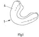
- a complete tooth protection device 1 is shown. It consists of a rail made of deep-drawable plastic, in particular EVA, which is adapted to a toothed jaw of a user and is approximately U-shaped in cross-section.
- the rail has two plastic films laminated on top of one another with an insert 2 in between.
- the insert 2 has a length which corresponds to several teeth of the toothed jaw and is preferably provided in a central front area of the toothed jaw facing away from the palate of the user. The width corresponds roughly to the height of the teeth to the gums.
- the insert 2 is a molded part made of light-curing or laser-curing plastic that is produced by means of a 3-D printer.
- Such an insert 2 can consist of the same material and the same hardness throughout. However, it can also consist of material of different hardness, so that, for example, there is a higher hardness in the middle area of the insert than in the end areas of the insert 2.
- the layer thickness of the insert 2 can for example be between 0.5 mm and 5 mm and vary over its longitudinal and vertical extent.
- the inlay 2 which is no longer visible there, is protruded on all sides by the plastic films, the plastic films in the protruding area lying directly on top of one another and being laminated on one another, so that a secure and firm fit and a secure connection of the parts with one another is achieved.
- the first plastic film 3 lying next to the toothed jaw has a contouring adapted to the shape of the jaw including the teeth.
- the insert 2 has the same contouring on its side facing the first plastic film 3 and on this side.
- the second plastic film 4 applied to the insert 2 has correspondingly adapted shapes on its side lying against the insert 2 and in the protruding area against the first plastic film 3, which are produced by the deep-drawing process. A flat, full contact between the parts is achieved and ensured.
- the plastic films 1,3 are firmly connected to one another in the area in which they lie directly on top of one another.
- the molded part 2, which is positioned between the plastic films 3, 4, but is arranged without being bonded to it, is projected over on all sides by the plastic films 3, 4.
- the hollow shape of a toothed jaw is first formed by means of an impression with the aid of an impression compound.
- This hollow form is filled with a pourable, hardenable compound and a model 5 of the toothed jaw is made in this way.
- the first deep-drawing film 3 is placed on the model 5, heated and, preferably by means of a vacuum, molded onto the model, as in FIG Figure 2 shown below. Thereby the contours of the dentate jaw are in the foil molded. From the surface of the first deep-drawing film 3 formed in this way, which is preferably still held by the model 5, the shape and the like essential data is recorded by means of a scanner and transferred to a data memory.
- the molded part 2 is produced by means of a 3-D printer, into which the data is read and processed for the purpose of production.
- the 3-D molded part 2 produced in this way is placed as an insert 2 on the first deep-drawing film 3 located on the model 5.
- the second deep-drawing film 4 is placed on the insert 2 and the region of the first deep-drawing film 3 protruding beyond the insert 2 in every direction, heated and preferably molded on by means of a vacuum. This creates a product like the one shown in Figure 1 is shown.
Landscapes
- Engineering & Computer Science (AREA)
- Materials Engineering (AREA)
- Chemical & Material Sciences (AREA)
- Manufacturing & Machinery (AREA)
- Health & Medical Sciences (AREA)
- Mechanical Engineering (AREA)
- Physics & Mathematics (AREA)
- Optics & Photonics (AREA)
- Physical Education & Sports Medicine (AREA)
- General Health & Medical Sciences (AREA)
- Oral & Maxillofacial Surgery (AREA)
- Environmental & Geological Engineering (AREA)
- Toxicology (AREA)
- Dental Tools And Instruments Or Auxiliary Dental Instruments (AREA)
Description
- Die Erfindung betrifft eine Zahnschutzvorrichtung, bestehend aus einer einem bezahnten Kiefer eines Benutzers angepassten, im Querschnitt etwa U-förmigen oder rinnenförmigen Schiene aus tiefziehfähigem Kunststoff, vorzugsweise aus Ethylenvinylacetat (EVA), wobei die Schiene zwei aufeinander laminierte Kunststofffolien mit dazwischen befindlicher Einlage aufweist, die vornehmlich in einem dem Gaumen des Benutzers abgewandten mittleren Frontbereich vorgesehen ist und eine seitliche Erstreckung aufweist, die mehreren Zähnen des Benutzers entspricht sowie eine Breite aufweist, die einer Abmessung von einem etwas überdeckbaren Zahnspitzenbereich bis zum Zahnfleisch entspricht, sowie ein Verfahren zur Herstellung einer Zahnschutzvorrichtung.
- Zahnschutzvorrichtungen der angegebenen Art sind im Stand der Technik bekannt. Bisher wurden solche Zahnschutzvorrichtungen als Tiefziehteile hergestellt. Hierbei wurde zum Zwecke der Herstellung zunächst eine Hohlform eines bezahnten Kiefers eines entsprechenden Patienten mit Hilfe eines Abdruckes mit Hilfe einer Abdruckmasse geformt. Diese Hohlform wurde dann dazu genutzt, diese mit einer gießfähigen aushärtbaren Masse zu befüllen, sodass dann ein Modell des bezahnten Kiefers zur Verfügung stand. Zur Anfertigung der Zahnschutzvorrichtung wurde dann auf dieses Modell eine erste Tiefziehfolie aufgelegt, erwärmt und mittels vorzugsweise Vakuum oder auch mittels Überdruck auf das Modell aufgeformt, sodass die Konturen des bezahnten Kiefers ausgeformt wurden. Nachfolgend oder gleichzeitig wurde eine weitere Tiefziehfolie aufgelegt, die praktisch eine Einlage in der Mundschutzvorrichtung bewirken sollte, sodass diese in einem bestimmten Bereich materialstärker und höher beanspruchbar ausgebildet sein konnte. Auf diese Einlage wurde eine weitere Tiefziehfolie aufgebracht. Anschließend wurde ein weiterer Tiefziehvorgang vorgenommen, sodass das Einlageteil und die zweite Tiefziehfolie ebenfalls auf dem Modell übergreifend die erste Tiefziehfolie aufgebracht werden konnte. Die so tiefgezogene Kombination der Einzelteile konnte dann nach Abkühlung abgenommen werden, sodass die fertige Zahnschutzvorrichtung zur Verfügung gestellt werden konnte.
- Die herkömmliche Ausgestaltung war lediglich dazu geeignet, Zahnschutzvorrichtungen zur Verfügung zu stellen, die hinsichtlich ihrer Form, Schichtstärke, Flexibilität und dergleichen sehr eingeschränkt war, weil sowohl die Schichtdicke des Einlageteiles nicht unterschiedlich eingestellt werden konnte, aber auch aufgrund der relativen Härte des Materials der Einlage nur kleinere Bereiche des zu schützenden Kiefers bei der Zahnschutzvorrichtung mit einer entsprechenden Einlage ausgestattet werden konnten, so beispielsweise nur die Bereich von jeweils drei Zähnen rechts und links der Kiefermitte.
- Solche Zahnschutzvorrichtungen werden besonders häufig zum Schutz von Sportlern eingesetzt, wobei die Zahnschutzvorrichtung mit dem darin befindlichen Einsatz dazu dient, eine Kraftverteilung von Schlägen und Stößen auf eine größere Fläche zu erreichen. Bei unterschiedlichen Sportarten werden unterschiedliche Verletzungsmuster bewirkt. Beispielsweise beim Hockeysport trifft der Schläger unter Umständen mit sehr hoher Kraft auf eine nur sehr kleine Fläche in Gegensatz zum Boxsport, bei dem der großflächige, gepolsterte Handschuh, auf eine große Fläche trifft. Daher müssen, um eine perfekte Schutzwirkung zu garantieren, die Zahnschutzvorrichtungen dem Sport angepasst werden. Dies ist mit der herkömmlichen Technik nur unzureichend möglich. Üblicherweise werden bei bisherigen Zahnschutzvorrichtungen, die im Wege des Tiefziehens hergestellt werden, Folien einer Schichtdicke von 3 mm eingesetzt. Bei diesen Tiefziehfolien handelt es sich um relativ elastische Folien, die einen hohen Tragekomfort haben. Die Einlageteile sind im Regelfall härter und demzufolge auch wesentlich schlechter im Wege des Tiefziehvorganges einzuarbeiten. Aus diesem Grunde sind die herkömmlichen Einlagen nur in einem begrenzten Bereich des Kiefers einsetzbar, vorzugsweise im vorderen Bereich von drei Zähnen rechts und links der Mitte. Eine größere Ausdehnung des Zahnschutzes ist kaum möglich und nicht üblich, weil entsprechende Verformungen im Wege des Tiefziehens für größere Einlageteile schwer realisierbar sind.
- Aus der
AT 7 980 U1 - Die
FR 2 576 798 A1 - Ausgehend von diesem Stand der Technik liegt der Erfindung die Aufgabe zugrunde, eine Zahnschutzvorrichtung gattungsgemäßer Art zu schaffen und ebenso ein Verfahren zu deren Herstellung, wobei eine bessere Schutzwirkung erreicht werden soll, eine bessere Anpassung an unterschiedliche Sportarten erzielt werden soll und ein besserer Schutz des bezahnten Kiefers des Benutzers über eine größere Breite, also nicht nur über drei Zähne rechts und links der Mitte.
- Zur Lösung dieser Aufgabe schlägt die Erfindung vor, dass die Einlage ein mittels eines 3-D-Druckers erzeugtes 3-D-Formteil aus licht- oder laserhärtendem Kunststoff ist, wobei die Schichtdicke des Formteils variiert, und dass die Einlage eine seitliche Erstreckung hat, die mehr aus einer Breite von sechs Zähnen entspricht, vorzugsweise bis zu 10 Zähnen, ganz bevorzugt der Gesamtlänge eines bezahnten Kiefers eines Benutzers, und dass die Schichtstärke der Einlage zwischen 0,5 mm und 5 mm beträgt.
- Gemäß der Erfindung wird die Einlage mittels eines 3-D-Druckers erzeugt, sodass hierdurch ein 3-D-Formteil aus licht- oder laserhärtendem Kunststoff zur Verfügung gestellt ist. Diese Einlage kann zwischen die tiefziehfähigen Kunststofffolien eingebracht werden und rezessive kann der Umformvorgang vorgenommen werden, wobei es nicht erforderlich ist, das mittels des 3-D-Druckers erzeugte Formteil im Wege des Tiefziehens weiter zu verarbeiten, sondern dieses Teil wird in seiner originär hergestellten Form, Größe, Abmessung und Dicke eingebracht und nach dem Umformen der ersten tiefziehfähigen Kunststofffolie auf dem Modell auf diese Folie aufgebracht und lagerichtig positioniert, wobei dann die zweite tiefziehfähige Folie aufgebracht und tiefgezogen wird, sodass dann die komplette Zahnschutzvorrichtung zur Verfügung gestellt ist.
- Als tiefziehfähige Folien werden vorzugsweise Ethylenvinylacetat-Copolymer-Folien (EVA) eingesetzt. Die Einlage, die ein mittels des 3-D-Druckers erzeugtes Formteil ist, kann dem entsprechenden Anwendungszweck sehr einfach angepasst werden, in dem die Schichtdicke des Formteiles variiert wird. Maßliche Beschränkungen sind hierbei prinzipiell nicht gegeben, weil eine Umformung des Formteiles im Wege des Tiefziehens, wie dies im Stand der Technik üblich ist, nicht erforderlich ist.
- Die Ausbildung der Einlage in Form eines 3-D-Druckteiles ermöglicht es, dessen seitliche Erstreckung bis praktisch über den gesamten zu schützenden Kiefer vorzunehmen. Zudem kann die Höhenerstreckung der Einlage bis zu den Spitzen der Zähne oder auch über diese Spitzen hinaus erfolgen, wobei dann eine entsprechende Abwinklung oder Abrundung vorzusehen ist. Alles dies ist im Wege eines 3-D-Druckverfahrens einfach zu realisieren.
- Die Schichtstärke wird in Abhängigkeit von der ausgeübten Sportart variiert und vorgesehen. Da die Einlage nicht nochmals durch den Tiefziehvorgang umgeformt werden muss, ist eine relativ dicke Ausbildung von bis zu 5 mm möglich. Besonders bevorzugt ist vorgesehen, dass die Einlage ein Formteil aus Acrylaten, Methacrylaten, Epoxiden, Vinylethern, Vinylestern, Styrolderivaten, Thiol-En-Systemen oder Mischungen davon ist.
- Solche Materialien sind licht- bzw. laserhärtende Kunststoffe, aus denen in einem generativen Verfahren individuelle Formteile für Zahnschutzvorrichtungen hergestellt werden können.
- Zudem kann bevorzugt sein, dass das Formteil Farbstoffe beinhaltet.
- Die vorzugsweise bearbeiteten zuvor angeführten lichthärtenden Kunststoffe, können Farbstoffe und weitere Initiatoren beinhalten, sodass durch Einsatz von unterschiedlichen Farben, unterschiedliche Produktgenerationen kenntlich gemacht werden können.
- Besonders bevorzugt ist vorgesehen, dass die Einlage aus Material mit unterschiedlicher Härte besteht.
- Die im Wege des 3-D-Drucks erzeugte Einlage kann in einfacher Weise unterschiedliche Härtegerade aufweisen, wie dies der Beanspruchung entspricht. Dabei können die Härtegrade in einer einzigen Einlage variiert werden, um ein besonders hervorragendes Produkt zur Verfügung zu stellen.
- Vorzugsweise ist dabei vorgesehen, dass die Einlage aus Material einer Härte von zwischen 35 und 90 Shore A besteht.
- Höhenerstreckung der Einlage bis zu den Spitzen der Zähne oder auch über diese Spitzen hinaus erfolgen, wobei dann eine entsprechende Abwinklung oder Abrundung vorzusehen ist. Alles dies ist im Wege eines 3-D-Druckverfahrens einfach zu realisieren.
- Auch kann vorgesehen sein, dass die Kunststofffolien zumindest teilweise opak sind.
- Bei einer mindestens teilweise opaken Ausbildung der Kunststofffolien wird erreicht, dass das Einlageteil kaschiert oder teilweise oder vollständig unsichtbar wird.
- Auch kann vorgesehen sein, dass die Einlage Hohlräume, Vertiefungen und/oder Lochungen aufweist.
- Diese Ausgestaltung ermöglicht es, eine Zahnschutzvorrichtung in besonderer Weise auszugestalten. So ist es möglich, durch Hohlräume, Vertiefungen oder Lochungen eine Gewichtserleichterung zu erreichen. Auch kann die mechanische Elastizität der Einlage durch solche Ausgestaltungen in bestimmter Weise beeinflusst werden. Die Einlage kann solche Ausgestaltungen auch beispielsweise in Form von Gitterstrukturen aufweisen.
- Vorzugsweise ist dabei vorgesehen, dass die Hohlräume, Vertiefungen und/oder Lochungen nicht vom Material der Kunststofffolien gefüllt sind.
- Durch die entsprechende Ausgestaltung wird erreicht, dass die Hohlräume oder dergleichen erhalten bleiben, auch wenn die weiteren Kunststofffolien im Wege des Tiefziehens aufgebracht sind, sodass die von den entsprechenden Gestaltungen erwünschten Funktionen aufrechterhalten bleiben, auch wenn die weiteren Kunststofffolien aufgebracht sind.
- Insbesondere kann auch vorgesehen sein, dass mindestens einige der Hohlräume, Vertiefungen und/oder Lochungen mit Gel gefüllt sind.
- Eine solche Ausgestaltung kann beispielsweise zu besseren Schockabsorptionen hilfreich sein.
- Bevorzugt ist zudem vorgesehen, dass die Einlage allseitig von den Kunststofffolien überragt ist und die Kunststofffolien im überragenden Bereich unmittelbar aufeinanderliegen und aufeinander laminiert sind.
- Durch eine solche Ausgestaltung wird erreicht, dass auf mechanische Retentionen verzichtet werden kann, da ein fester mechanischer Halt erzeugt ist und eine Positionsveränderung ausgeschlossen werden kann.
- Bei dem Endprodukt, also der Zahnschutzvorrichtung, ist die Einlage allseitig von den Kunststofffolien überragt. Diese Kunststofffolien sind (nur) in den überragenden Bereichen unmittelbar aufeinanderliegend miteinander verbunden, sodass hierdurch der Zusammenhalt und die Positionssicherung erreicht ist.
- Zudem kann vorgesehen sein, dass die Einlage vorzugsweise quer zu ihrer Längserstreckung mindestens eine Sollbruchstelle aufweist.
- Solche Zahnschutzvorrichtungen können Sollbruchstellen aufweisen, damit bei bestimmten Einsätzen, also bestimmten Sportarten, verschiedenen möglichen Verletzungsmustern Rechnung getragen werden kann. Ob und in wie fern und an welcher Stelle eine solche Ausgestaltung von Sollbruchstellen sinnvoll ist, ist im Einzelfall zu entscheiden. Wesentlich ist die Tatsache, dass in einfacher Weise solche Sollbruchstellen bei der Herstellung des Formteiles mittels 3-D-Drucker eingebracht werden können.
- Auch kann vorgesehen sein, dass die Einlage aus radio-opakem Material besteht, insbesondere röntgen-opak ist.
- Bei radio-opakem Material kann es sich beispielsweise um ein Bleigummimaterial handeln, welches aufgrund seiner Struktur im Gegensatz zu den eingesetzten Tiefziehfolien röntgen-opak ist, das heißt auf einem Röntgenbild sichtbar ist. Sofern ein Sportler unerwünschter Weise einen solchen Zahnschutz aspiriert, also im Extremfall verschluckt, so kann in einfacher Weise röntgenologisch der Sitz des Mundschutzes im Körper des Benutzers sichtbar gemacht werden, um eine Notoperation durchzuführen.
- Ein besonderer Vorteil wird darin gesehen, dass die dem bezahnten Kiefer zu benachbarende erste Kunststofffolie eine der Form des Kiefers samt Zähnen angepasste Konturierung aufweist, dass die Einlage auf der der ersten Kunststofffolie zugewandten, an dieser anliegenden Seite die gleiche Konturierung aufweist und dass die zweite auf die Einlage aufgebrachte Kunststofffolie auf ihrer an dieser Einlage anliegenden Seite und an dem überstehenden Teil über die erste Kunststofffolie an dieser anliegenden Bereich der Form der Außenseite der Einlage und der Anlagefläche der ersten Kunststofffolie folgend flächig anliegt.
- Durch die besondere Herstellungsweise der Zahnschutzvorrichtung im Wege des 3-D-Druckens ist es möglich, die Einlage auf der der ersten Kunststofffolie zugewandten Seite, die im Tiefziehvorgang die Konturierung des bezahnten Kiefers erhält, ebenfalls mit einer solchen Konturierung vorzusehen, sodass ein sicherer Passsitz zwischen der Einlage und der ersten Kunststofffolie erreicht wird. Dies ist mit herkömmlicher Technik schwer erreichbar.
- Auch das Aufbringen der zweiten Kunststofffolie führt dazu, dass eine exakte Anpassung an die Einlage erfolgt, sodass insgesamt sowohl ein sicherer Sitz als auch eine vorzügliche Positionshalterung der Teile zueinander im Endzustand erreicht ist.
- Zudem ist bevorzugt vorgesehen, dass die Kunststofffolien in den Bereichen, in denen sie unmittelbar aufeinanderliegen, fest miteinander verbunden sind und das Formteil zwischen den Kunststofffolien positioniert ist, aber ohne Bindung mit diesen geringfügig beweglich gehalten ist.
- Gegenstand der Erfindung ist ferner ein Verfahren zur Herstellung einer Zahnschutzvorrichtung, insbesondere nach einem der Ansprüche 1 bis 15, wobei eine Hohlform eines bezahnten Kiefers mittels eines Abdruckes mit Hilfe einer Abdruckmasse geformt wird, die Hohlform mit einer gießfähigen, aushärtbaren Masse gefüllt und so ein Modell des bezahnten Kiefers angefertigt wird, welches vorzugsweise gehärtet, insbesondere lichtgehärtet wird, auf das Modell eine erste Tiefziehfolie aufgelegt, erwärmt und mittels Vakuum oder Überdruck auf das Modell aufgeformt wird, sodass die Konturen des bezahnten Kiefers ausgeformt werden.
- Erfindungsgemäß ist zur Erzeugung einer entsprechenden Zahnschutzvorrichtung vorgesehen, dass von der Fläche der so umgeformten ersten Tiefziehfolie, die noch von dem Modell gehalten wird, mittels eines Scanners die Formdaten, in dem Bereich auf den eine Einlage aufgebracht werden soll, abgegriffen und in einem Datenerfasser/-speicher abgelegt werden, mittels der von dem Datenspeicher abgerufenen Daten und unter Hinzufügung der für die Einlage wesentlichen Daten, wie z.B. Materialstärke, mittels eines generativen Prozesses ein 3-D-Formteil mittels Drucker erzeugt wird, das so gefertigte 3-D-Formteil als Einlage auf die auf dem Modell befindliche tiefgezogene erste Tiefziehfolie aufgebracht wird, anschließend die zweite Tiefziehfolie auf die Einlage und den die Einlage in jeder Richtung überragenden Bereich der ersten Tiefziehfolie aufgelegt, erwärmt und mittels Vakuum oder Überdruck aufgeformt wird, nachfolgend vorzugsweise eine Abkühlung vorgenommen wird und dann die fertige Zahnschutzvorrichtung von dem Modell abgenommen wird, wobei die Einlage eine seitliche Erstreckung hat, die mehr als einer Breite von sechs Zähnen entspricht, vorzugsweise bis zu 10 Zähnen, ganz bevorzugt der Gesamtlänge eines bezahnten Kiefers eines Benutzers, und die Schichtstärke der Einlage zwischen 0,5 mm und 5 mm beträgt.
- In herkömmlicher Weise wird zunächst eine Hohlform eines bezahnten Kiefers mittels eines Abdruckes und mit Hilfe einer Abdruckmasse hergestellt. Diese Hohlform wird dann zur Herstellung eines Modelles des bezahnten Kiefers benutzt. Auf dieses Modell wird dann die erste Tiefziehfolie aufgelegt, erwärmt und mittels vorzugsweise Vakuum auf das Modell aufgeformt, sodass dessen Konturen abgebildet sind. Von der Fläche der so umgeformten ersten Tiefziehfolie, die noch von dem Modell gehalten wird, wird beispielsweise eines Scanners die Form erfasst und die Formdaten werden insbesondere in dem Bereich, auf den eine Einlage aufgebracht werden soll, abgenommen und in einen Datenerfasserspeicher übertragen und abgelegt. Mittels der von dem Datenspeicher abrufbaren Daten können unter Hinzufügung weiterer für das Produkt wesentlicher Daten, wie zum Beispiel die Materialstärke, mittels eines generativen Prozesses 3-D-Formteile mittels des Druckers erzeugt werden. Ein so gefertigtes 3-D-Formteil bildet die Einlage, die auf die noch im Modell befindliche tiefgezogene erste Tiefziehfolie aufgebracht wird. Die Lagepositionierung in der richtigen Position ist dadurch vereinfacht, dass die Einlage auf der Seite, die der ersten Tiefziehfolie zugewandt ist, entsprechend konturiert ist, sodass der richtige Sitz durch die passende Zusammenlegung der Konturen erreicht wird. Anschließend kann die zweite Tiefziehfolie auf die Einlage und den die Einlage in jeder Richtung überragenden Bereich der ersten Tiefziehfolie aufgelegt, erwärmt und aufgeformt werden. Nachfolgend kann eine Abkühlung vorgenommen werden oder es kann auch eine Abkühlung durch Luft erfolgen. Sobald eine ausreichend Abkühlung erfolgt ist, kann die fertige Zahnschutzvorrichtung von dem Modell abgenommen werden und steht zur Benutzung zur Verfügung.
- Vorzugsweise wird als Medium für das Aufformen im Wege des Tiefziehens Luft verwendet.
- Bevorzugt ist vorgesehen, dass die erste Tiefziehfolie mit der zweiten Tiefziehfolie in den Bereichen, in denen die beiden Folien aufeinander liegen mittels des Vakuums oder des Überdrucks fest und unlösbar miteinander verbunden werden, insbesondere laminiert werden, während das Material der Tiefziehfolien keine Bindung mit dem Material der Einlage eingeht.
- Die Wirkung dieser Verfahrensweise ist schon hinsichtlich der Merkmale der Zahnschutzvorrichtung angegeben worden.
- Ein schematisches Ausführungsbeispiel der Erfindung ist in der Zeichnung dargestellt und im Folgenden näher beschrieben.
- Es zeigt:
- Fig. 1
- eine komplette Zahnschutzvorrichtung in Ansicht;
- Fig. 2
- eine Explosionsdarstellung von Teilen der erfindungsgemäßen Zahnschutzvorrichtung;
- Fig. 3
- eine Einzelheit der Zahnschutzvorrichtung in Ansicht;
- Fig. 4
- eine Ansicht, bei der die Teile gemäß
Figur 2 aufeinandergefügt sind. - In der
Figur 1 ist eine komplette Zahnschutzvorrichtung 1 gezeigt. Sie besteht aus einer einem bezahnten Kiefer eines Benutzers angepassten, im Querschnitt etwa U-förmigen Schiene aus tiefziehfähigem Kunststoff, insbesondere EVA. Die Schiene weist zwei aufeinander laminierte Kunststofffolien mit dazwischen befindlicher Einlage 2 auf. Die Einlage 2 weist eine Länge auf, die mehreren Zähnen des bezahnten Kiefers entspricht und ist vorzugweise in einem dem Gaumen des Benutzers abgewandten mittleren Frontbereich des bezahnten Kiefers vorgesehen. Die Breite entspricht etwa der Höhe der Zähne bis zum Zahnfleisch. - Bei der Einlage 2 handelt es sich um ein mittels eines 3-D-Druckers erzeugtes Formteil aus licht- oder laserhärtendem Kunststoff. Eine solche Einlage 2 kann durchgängig aus gleichem Material und gleicher Härte bestehen. Sie kann aber auch aus Material unterschiedlicher Härte bestehen, sodass beispielsweise im Mittelbereich der Einlage eine höhere Härte als in den Endbereichen der Einlage 2 vorliegt. Die Schichtstärke der Einlage 2 kann beispielsweise zwischen 0,5 mm und 5 mm betragen und über deren Längs- und Höhenerstreckung variieren. Bei der fertigen Zahnschutzvorrichtung gemäß
Figur 1 ist die dort nicht mehr sichtbare Einlage 2 allseitig von den Kunststofffolien überragt, wobei die Kunststofffolien in dem überragenden Bereich unmittelbar aufeinander liegen und aufeinander laminiert sind, sodass ein sicherer und fester Sitz und eine sichere Verbindung der Teile miteinander erreicht ist. - Die dem bezahnten Kiefer zunächst liegende erste Kunststofffolie 3 weist eine der Form des Kiefers samt Zähnen angepasste Konturierung auf. Die Einlage 2 weist auf ihrer der ersten Kunststofffolie 3 zugewandten und an dieser anliegenden Seite die gleiche Konturierung auf. Die zweite auf die Einlage 2 aufgebrachte Kunststofffolie 4 weist auf ihrer an der Einlage 2 anliegenden und im überstehenden Bereich an der ersten Kunststofffolie 3 anliegende Seite entsprechend angepasste Formen auf, die durch den Tiefziehvorgang erzeugt werden. Es wird damit eine flächige, satte Anlage der Teile aneinander erreicht und sichergestellt. Die Kunststofffolien 1,3 sind in dem Bereich, in denen sie unmittelbar aufeinander liegen, fest miteinander verbunden. Das Formteil 2, welches zwischen den Kunststofffolien 3,4 positioniert ist, aber ohne Bindung mit diesem angeordnet ist, wird allseitig von den Kunststofffolien 3,4 überragt.
- Zur Herstellung einer solchen Zahnschutzvorrichtung 1 wird zunächst die Hohlform eines bezahnten Kiefers mittels eines Abdruckes mit Hilfe einer Abdruckmasse geformt. Diese Hohlform wird mit einer gießfähigen aushärtbaren Masse befüllt und so ein Modell 5 des bezahnten Kiefers angefertigt. Beim Herstellungsvorgang wird auf das Modell 5 die erste Tiefziehfolie 3 aufgelegt, erwärmt und mittels vorzugsweise Vakuum auf das Modell aufgeformt, wie in
Figur 2 unterer Bereich gezeigt. Dabei werden die Konturen des bezahnten Kiefers in der Folie aufgeformt. Von der Fläche der so umgeformten ersten Tiefziehfolie 3, die vorzugsweise noch von dem Modell 5 gehalten wird, wird mittels eines Scanners die Form und dergleichen wesentliche Daten erfasst und in einen Datenspeicher übertragen. Im Datenspeicher werden weitere Daten hinzugefügt, beispielsweise über die Dicke der Einlage. Mittels eines generativen Prozesses wird das Formteil 2 mittels eines 3-D-Druckers erzeugt in den die Daten zum Zwecke der Herstellung eingelesen und verarbeitet werden. Das so gefertigte 3-D-Formteil 2 wird als Einlage 2 auf die auf dem Modell 5 befindliche erste Tiefziehfolie 3 aufgesetzt. Anschließend wird die zweite Tiefziehfolie 4 auf die Einlage 2 und den die Einlage 2 in jeder Richtung überragenden Bereich der ersten Tiefziehfolie 3 aufgelegt, erwärmt und mittels vorzugsweise Vakuum aufgeformt. Hierdurch wird ein Produkt erzeugt, wie es inFigur 1 gezeigt ist. - Die Erfindung ist nicht auf das Ausführungsbeispiel beschränkt, sondern im Rahmen der Offenbarung vielfach variabel.
Claims (18)
- Zahnschutzvorrichtung (1), bestehend aus einer einem bezahnten Kiefer eines Benutzers angepassten, im Querschnitt etwa U-förmigen oder rinnenförmigen Schiene aus tiefziehfähigem Kunststoff, vorzugsweise aus Ethylenvinylacetat (EVA), wobei die Schiene zwei aufeinander laminierte Kunststofffolien (3,4) mit dazwischen befindlicher Einlage (2) aufweist, die vornehmlich in einem dem Gaumen des Benutzers abgewandten mittleren Frontbereich vorgesehen ist und eine seitliche Erstreckung aufweist, die mehreren Zähnen des Benutzers entspricht sowie eine Breite aufweist, die von einem etwas überdeckbaren Zahnspitzenbereich bis zum Zahnfleisch entspricht, dadurch gekennzeichnet, dass die Einlage (2) ein mittels eines 3-D-Druckers erzeugtes 3-D-Formteil aus licht- oder laserhärtendem Kunststoff ist, wobei die Schichtdicke des Formteils variiert, und dass die Einlage (2) eine seitliche Erstreckung hat, die mehr aus einer Breite von sechs Zähnen entspricht, vorzugsweise bis zu 10 Zähnen, ganz bevorzugt der Gesamtlänge eines bezahnten Kiefers eines Benutzers, und dass die Schichtstärke der Einlage (2) zwischen 0,5 mm und 5 mm beträgt.
- Vorrichtung nach Anspruch 1, dadurch gekennzeichnet, dass die Einlage (2) ein Formteil aus Acrylaten, Methacrylaten, Epoxiden, Vinylethern, Vinylestern,Styrolderivaten, Thiol-En-Systemen oder Mischungen davon ist.
- Vorrichtung nach Anspruch 1 oder 2, dadurch gekennzeichnet, dass das Formteil Farbstoffe beinhaltet.
- Vorrichtung nach einem der Ansprüche 1 bis 3, dadurch gekennzeichnet, dass die Kunststofffolien (3,4) aus klarsichtigem Material besteht.
- Vorrichtung nach einem der Ansprüche 1 bis 4, dadurch gekennzeichnet, dass die Einlage (2) aus Material mit unterschiedlicher Härte besteht.
- Vorrichtung nach Anspruch 5, dadurch gekennzeichnet, dass die Einlage (2) aus Material einer Härte von zwischen 35 und 90 Shore A besteht.
- Vorrichtung nach einem der Ansprüche 1 bis 6, dadurch gekennzeichnet, dass die Kunststofffolien (3,4) zumindest teilweise opak sind.
- Vorrichtung nach einem der Ansprüche 1 bis 7, dadurch gekennzeichnet, dass die Einlage (2) Hohlräume, Vertiefungen und/oder Lochungen aufweist.
- Vorrichtung nach Anspruch 8, dadurch gekennzeichnet, dass die Hohlräume, Vertiefungen und/oder Lochungen nicht vom Material der Kunststofffolien (3,4) gefüllt sind.
- Vorrichtung nach Anspruch 8 oder 9, dadurch gekennzeichnet, dass mindestens einige der Hohlräume, Vertiefungen und/oder Lochungen mit Gel gefüllt sind.
- Vorrichtung nach einem der Ansprüche 1 bis 10, dadurch gekennzeichnet, dass die Einlage (2) allseitig von den Kunststofffolien (3,4) überragt ist und die Kunststofffolien (3,4) im überragenden Bereich unmittelbar aufeinanderliegen und aufeinander laminiert sind.
- Vorrichtung nach einem der Ansprüche 1 bis 11, dadurch gekennzeichnet, dass die Einlage (2) vorzugsweise quer zu ihrer Längserstreckung mindestens eine Sollbruchstelle aufweist.
- Vorrichtung nach einem der Ansprüche 1 bis 12, dadurch gekennzeichnet, dass die Einlage (2) aus radio-opakem Material besteht, insbesondere röntgen-opak ist.
- Vorrichtung nach einem der Ansprüche 1 bis 13, dadurch gekennzeichnet, dass die dem bezahnten Kiefer zu benachbarende erste Kunststofffolie (3) eine der Form des Kiefers samt Zähnen angepasste Konturierung aufweist, dass die Einlage (2) auf der der ersten Kunststofffolie (3) zugewandten, an dieser anliegenden Seite die gleiche Konturierung aufweist und dass die zweite auf die Einlage (2) aufgebrachte Kunststofffolie (4) auf ihrer an dieser Einlage (2) anliegenden Seite und an dem überstehenden Teil über die erste Kunststofffolie (3) an dieser anliegenden Bereich der Form der Außenseite der Einlage (2) und der Anlagefläche der ersten Kunststofffolie (3) folgend flächig anliegt.
- Vorrichtung nach einem der Ansprüche 1 bis 14, dadurch gekennzeichnet, dass die Kunststofffolien (3,4) in den Bereichen, in denen sie unmittelbar aufeinander liegen, fest miteinander verbunden sind und das Formteil (2) zwischen den Kunststofffolien (3,4) positioniert ist, aber ohne Bindung mit diesen geringfügig beweglich gehalten ist.
- Verfahren zur Herstellung einer Zahnschutzvorrichtung (1), insbesondere nach einem der Ansprüche 1 bis 15, wobei eine Hohlform eines bezahnten Kiefers mittels eines Abdruckes mit Hilfe einer Abdruckmasse geformt wird, die Hohlform mit einer gießfähigen, aushärtbaren Masse gefüllt und so ein Modell (5) des bezahnten Kiefers angefertigt wird, auf das Modell (5) eine erste Tiefziehfolie (3) aufgelegt, erwärmt und mittels Vakuum oder Überdruck auf das Modell (5) aufgeformt wird, sodass die Konturen des bezahnten Kiefers ausgeformt werden, dadurch gekennzeichnet, dass von der Fläche der so umgeformten ersten Tiefziehfolie (3), die vorzugsweise noch von dem Modell (5) gehalten wird, mittels eines Scanners die Formdaten, in dem Bereich auf den eine Einlage (2) aufgebracht werden soll, abgegriffen und in einem Datenerfasser/- speicher abgelegt werden, mittels der von dem Datenspeicher abgerufenen Daten und unter Hinzufügung der für die Einlage (2) wesentlichen Daten, wie z.B. Materialstärke, mittels eines generativen Prozesses ein 3-D-Formteil mittels Drucker erzeugt wird, das so gefertigte 3-D-Formteil als Einlage (2) auf die auf dem Modell (5) befindliche tiefgezogene erste Tiefziehfolie (3) aufgebracht wird, anschließend die zweite Tiefziehfolie (4) auf die Einlage (2) und den die Einlage (2) in jeder Richtung überragenden Bereich der ersten Tiefziehfolie (3) aufgelegt, erwärmt und mittels Vakuum oder Überdruck aufgeformt wird, nachfolgend vorzugsweise eine Abkühlung vorgenommen wird und dann die fertige Zahnschutzvorrichtung (1) von dem Modell abgenommen wird, wobei die Einlage (2) eine seitliche Erstreckung hat, die mehr als einer Breite von sechs Zähnen entspricht, vorzugsweise bis zu 10 Zähnen, ganz bevorzugt der Gesamtlänge eines bezahnten Kiefers eines Benutzers, und die Schichtstärke der Einlage (2) zwischen 0,5 mm und 5 mm beträgt.
- Verfahren nach Anspruch 16, dadurch gekennzeichnet, dass als Medium für das Aufformen mittels Vakuum oder Überdruck Luft verwendet wird.
- Verfahren nach einem der Ansprüche 16 oder 17, dadurch gekennzeichnet, dass die erste Tiefziehfolie (3) mit der zweiten Tiefziehfolie (4) in den Bereichen, in denen die beiden Folien aufeinander liegen mittels des Vakuums oder des Überdrucks fest und unlösbar miteinander verbunden werden, insbesondere laminiert werden, während das Material der Tiefziehfolien keine Bindung mit dem Material der Einlage (2) eingeht.
Applications Claiming Priority (2)
| Application Number | Priority Date | Filing Date | Title |
|---|---|---|---|
| DE102017102101.9A DE102017102101A1 (de) | 2017-02-03 | 2017-02-03 | Zahnschutzvorrichtung |
| PCT/DE2018/100008 WO2018141325A1 (de) | 2017-02-03 | 2018-01-08 | Zahnschutzvorrichtung |
Publications (2)
| Publication Number | Publication Date |
|---|---|
| EP3544703A1 EP3544703A1 (de) | 2019-10-02 |
| EP3544703B1 true EP3544703B1 (de) | 2021-03-10 |
Family
ID=61007414
Family Applications (1)
| Application Number | Title | Priority Date | Filing Date |
|---|---|---|---|
| EP18700837.0A Active EP3544703B1 (de) | 2017-02-03 | 2018-01-08 | Zahnschutzvorrichtung und verfahren zu ihrer herstellung |
Country Status (8)
| Country | Link |
|---|---|
| US (1) | US11247117B2 (de) |
| EP (1) | EP3544703B1 (de) |
| JP (1) | JP2020510502A (de) |
| KR (1) | KR102469592B1 (de) |
| AU (1) | AU2018214527B2 (de) |
| DE (1) | DE102017102101A1 (de) |
| ES (1) | ES2869584T3 (de) |
| WO (1) | WO2018141325A1 (de) |
Families Citing this family (11)
| Publication number | Priority date | Publication date | Assignee | Title |
|---|---|---|---|---|
| US9925440B2 (en) | 2014-05-13 | 2018-03-27 | Bauer Hockey, Llc | Sporting goods including microlattice structures |
| US11684104B2 (en) | 2019-05-21 | 2023-06-27 | Bauer Hockey Llc | Helmets comprising additively-manufactured components |
| US11420105B2 (en) | 2020-03-04 | 2022-08-23 | Custom Club, Inc. | Oral device having wedges and method of manufacture |
| US11185148B2 (en) | 2020-03-06 | 2021-11-30 | Custom Club, Inc. | Oral device container and oral device container and bottle assembly |
| US11110192B1 (en) | 2020-03-06 | 2021-09-07 | Custom Club, Inc. | Oral device container and oral device sanitation system |
| GB2622897B (en) * | 2020-06-05 | 2025-02-19 | Orb Innovations Ltd | Fitness monitoring and tracking device |
| JP7072920B1 (ja) * | 2020-11-30 | 2022-05-23 | 株式会社ホワイトライン | マウスガードの製造方法 |
| KR102738045B1 (ko) * | 2022-04-13 | 2024-12-03 | 경북대학교 산학협력단 | 이갈이 방지 마우스피스 |
| EP4327899A1 (de) | 2022-08-22 | 2024-02-28 | Centre Hospitalier Universitaire Vaudois (CHUV) | Kundenspezifischer modularer mundschutz aus mehreren materialien und verfahren zu seiner herstellung |
| WO2024180530A1 (en) * | 2023-03-02 | 2024-09-06 | Meintjes Ralph Lancelot | Methods of fabricating a mouthguard |
| DE102024106253A1 (de) | 2024-03-05 | 2025-09-11 | Michael Thiel | Zahnschutz |
Family Cites Families (27)
| Publication number | Priority date | Publication date | Assignee | Title |
|---|---|---|---|---|
| US3223085A (en) * | 1963-12-02 | 1965-12-14 | Kenneth W Gores | Mouthguard |
| US3943924A (en) * | 1974-01-11 | 1976-03-16 | Northstar Athletic Industries, Inc. | Mouthpiece |
| FR2576798B1 (fr) * | 1985-02-05 | 1989-05-26 | Sametzky Serge | Protege-dents, notamment pour la pratique de sports violents et procede de fabrication |
| JPH03244480A (ja) * | 1990-02-23 | 1991-10-31 | Molten Corp | マウスガード |
| US5031638A (en) | 1990-03-13 | 1991-07-16 | Roll-A-Puck Limited | Direct-formed mouthguard, a blank for use in making the mouthguard and a method of making the mouthguard |
| US5241921A (en) * | 1992-07-15 | 1993-09-07 | Sadlak Michael W | Water skiing boom |
| JPH08206272A (ja) | 1995-02-06 | 1996-08-13 | Bayer Nippon Shika Kk | マウスガードの基体及びマウスガードの製作方法 |
| AUPP409898A0 (en) * | 1998-06-11 | 1998-07-09 | Signature Mouthguards Pty Limited | A mouthguard |
| GB0126414D0 (en) | 2001-11-02 | 2002-01-02 | Carmichael Paul C | Mouth guard |
| US6702575B2 (en) * | 2002-04-03 | 2004-03-09 | Jack Keith Hilliard | Orthodontic aligner auxiliary system |
| US20040154625A1 (en) * | 2002-12-31 | 2004-08-12 | Foley Timothy W. | Mouthguard and method of making the mouthguard |
| DE10315887B4 (de) * | 2003-04-08 | 2005-03-24 | Daimlerchrysler Ag | Wärmetauscher mit Befestigungselementen in einem Kraftfahrzeug |
| JP2004344623A (ja) * | 2003-05-23 | 2004-12-09 | Shiyoufuu:Kk | 歯科用構造物自動作製装置 |
| US20060084024A1 (en) * | 2004-10-14 | 2006-04-20 | Farrell Christopher J | Oral appliance |
| CN103126774B (zh) | 2004-10-14 | 2016-05-18 | 克里斯多佛·约翰·法雷尔 | 口腔器具 |
| AT7980U1 (de) * | 2005-03-08 | 2005-12-15 | Steinbach Robert | Zahnschutz |
| US20070084471A1 (en) * | 2005-10-14 | 2007-04-19 | Salvatore Napoli | Shock absorbing dental device |
| JP4506706B2 (ja) * | 2006-03-28 | 2010-07-21 | パナソニック電工株式会社 | 歯列矯正装置 |
| EP1913894A1 (de) * | 2006-10-16 | 2008-04-23 | KerrHawe SA | Zahndammklammer |
| CN101755238B (zh) * | 2007-04-13 | 2013-01-02 | 3D系统公司 | 二元光引发剂、可光固化的组合物、它们的用途以及制备三维制品的方法 |
| US7658193B2 (en) * | 2007-06-04 | 2010-02-09 | Hayloft Enterprises, Inc. | Interocclusal appliance and method |
| WO2011159299A1 (en) | 2010-06-17 | 2011-12-22 | Sport Guard, Inc. | Comfortable mouth guard |
| JP2013034740A (ja) * | 2011-08-10 | 2013-02-21 | Panasonic Corp | 電装品内蔵の歯科治療用マウスピースおよびそのマウスピース成形基材 |
| US8585401B2 (en) | 2012-02-17 | 2013-11-19 | Allen J. Moses | Mouthpiece for athletic performance enhancement |
| WO2015149127A1 (en) * | 2014-04-01 | 2015-10-08 | Oventus Pty Ltd | Breathing assist device |
| US9370707B2 (en) | 2014-05-13 | 2016-06-21 | Akervall Technologies, Inc. | Adaptive mouth guard and method of use |
| JP6686273B2 (ja) * | 2014-11-26 | 2020-04-22 | 大日本印刷株式会社 | ブロー成形方法 |
-
2017
- 2017-02-03 DE DE102017102101.9A patent/DE102017102101A1/de not_active Withdrawn
-
2018
- 2018-01-08 EP EP18700837.0A patent/EP3544703B1/de active Active
- 2018-01-08 JP JP2019563664A patent/JP2020510502A/ja active Pending
- 2018-01-08 ES ES18700837T patent/ES2869584T3/es active Active
- 2018-01-08 WO PCT/DE2018/100008 patent/WO2018141325A1/de not_active Ceased
- 2018-01-08 US US16/348,685 patent/US11247117B2/en active Active
- 2018-01-08 AU AU2018214527A patent/AU2018214527B2/en active Active
- 2018-01-08 KR KR1020197022881A patent/KR102469592B1/ko active Active
Non-Patent Citations (1)
| Title |
|---|
| None * |
Also Published As
| Publication number | Publication date |
|---|---|
| KR102469592B1 (ko) | 2022-11-22 |
| US11247117B2 (en) | 2022-02-15 |
| WO2018141325A1 (de) | 2018-08-09 |
| JP2020510502A (ja) | 2020-04-09 |
| AU2018214527B2 (en) | 2021-11-11 |
| US20190344150A1 (en) | 2019-11-14 |
| DE102017102101A1 (de) | 2018-08-09 |
| AU2018214527A1 (en) | 2019-07-25 |
| KR20190112277A (ko) | 2019-10-04 |
| ES2869584T3 (es) | 2021-10-25 |
| EP3544703A1 (de) | 2019-10-02 |
Similar Documents
| Publication | Publication Date | Title |
|---|---|---|
| WO2018141325A1 (de) | Zahnschutzvorrichtung | |
| DE19732248B4 (de) | Gebißschutz mit einem rechten und einem linken Schutzabschnitt für Backenzähne | |
| WO2017198514A1 (de) | Retainer sowie verfahren zu dessen herstellung | |
| EP1194051B1 (de) | Verfahren und vorrichtung zur herstellung von bürsten sowie danach hergestellte bürsten | |
| EP2337474B1 (de) | Verfahren zur herstellung von bürsten, insbesondere zahnbürsten | |
| EP0320590B2 (de) | Brustprothese | |
| EP3053541B1 (de) | Rohling zur herstellung eines zahnersatzes | |
| EP0470552A1 (de) | Matrize für die Dentalmedizin und eine Vorrichtung zur Herstellung von Matrizenbändern | |
| WO2012022748A1 (de) | Zahnschiene aus zwei kunststoffen mit unterschiedlichen härtegraden | |
| DE102014105190A1 (de) | Verfahren zur Bearbeitung von vorkonfektionierten Prothesenzähnen | |
| JP2020510502A5 (de) | ||
| DE102010036107A1 (de) | Dentales Tiefziehmaterial | |
| EP3572035B1 (de) | Dentalprothese, zugehöriges halbprodukt sowie bausatz | |
| DE102016004407A1 (de) | Werkzeug und Verfahren zur Herstellung eines Schaumkörpers, sowie Schaumstoffkörper | |
| EP0462509A1 (de) | Zahnbürste | |
| EP3852677A1 (de) | Vorprodukt zur herstellung von prothesenzähnen und verfahren zu dessen herstellung und verarbeitung | |
| EP2720655A1 (de) | Intraorales schnarchtherapiegerät | |
| DE202010013863U1 (de) | Luftdurchlässiger Helm | |
| DE102007001528B4 (de) | Verfahren zum Herstellen einer Zahnschienenmenge | |
| DE3221638A1 (de) | Verfahren zum herstellen von schutzhelmen | |
| EP1336468A2 (de) | Zahnriemen aus Kunststoff und Verfahren und Vorrichtung zum Herstellen eines Zahnriemens | |
| DE102009052867B4 (de) | Vorrichtung und Verfahren zum Herstellen von Bürstenkörpern oder Teil-Bürstenkörpern | |
| WO2025186128A1 (de) | Zahnschutz | |
| DE102017217718A1 (de) | Otoplastik | |
| DE102014011216B4 (de) | Verfahren zur zahnmedizinischen Mundabformung |
Legal Events
| Date | Code | Title | Description |
|---|---|---|---|
| STAA | Information on the status of an ep patent application or granted ep patent |
Free format text: STATUS: UNKNOWN |
|
| STAA | Information on the status of an ep patent application or granted ep patent |
Free format text: STATUS: THE INTERNATIONAL PUBLICATION HAS BEEN MADE |
|
| PUAI | Public reference made under article 153(3) epc to a published international application that has entered the european phase |
Free format text: ORIGINAL CODE: 0009012 |
|
| STAA | Information on the status of an ep patent application or granted ep patent |
Free format text: STATUS: REQUEST FOR EXAMINATION WAS MADE |
|
| 17P | Request for examination filed |
Effective date: 20190628 |
|
| AK | Designated contracting states |
Kind code of ref document: A1 Designated state(s): AL AT BE BG CH CY CZ DE DK EE ES FI FR GB GR HR HU IE IS IT LI LT LU LV MC MK MT NL NO PL PT RO RS SE SI SK SM TR |
|
| AX | Request for extension of the european patent |
Extension state: BA ME |
|
| STAA | Information on the status of an ep patent application or granted ep patent |
Free format text: STATUS: EXAMINATION IS IN PROGRESS |
|
| 17Q | First examination report despatched |
Effective date: 20200330 |
|
| DAV | Request for validation of the european patent (deleted) | ||
| DAX | Request for extension of the european patent (deleted) | ||
| GRAP | Despatch of communication of intention to grant a patent |
Free format text: ORIGINAL CODE: EPIDOSNIGR1 |
|
| STAA | Information on the status of an ep patent application or granted ep patent |
Free format text: STATUS: GRANT OF PATENT IS INTENDED |
|
| INTG | Intention to grant announced |
Effective date: 20200924 |
|
| GRAJ | Information related to disapproval of communication of intention to grant by the applicant or resumption of examination proceedings by the epo deleted |
Free format text: ORIGINAL CODE: EPIDOSDIGR1 |
|
| STAA | Information on the status of an ep patent application or granted ep patent |
Free format text: STATUS: EXAMINATION IS IN PROGRESS |
|
| GRAS | Grant fee paid |
Free format text: ORIGINAL CODE: EPIDOSNIGR3 |
|
| STAA | Information on the status of an ep patent application or granted ep patent |
Free format text: STATUS: GRANT OF PATENT IS INTENDED |
|
| INTG | Intention to grant announced |
Effective date: 20200924 |
|
| GRAA | (expected) grant |
Free format text: ORIGINAL CODE: 0009210 |
|
| STAA | Information on the status of an ep patent application or granted ep patent |
Free format text: STATUS: THE PATENT HAS BEEN GRANTED |
|
| AK | Designated contracting states |
Kind code of ref document: B1 Designated state(s): AL AT BE BG CH CY CZ DE DK EE ES FI FR GB GR HR HU IE IS IT LI LT LU LV MC MK MT NL NO PL PT RO RS SE SI SK SM TR |
|
| REG | Reference to a national code |
Ref country code: GB Ref legal event code: FG4D Free format text: NOT ENGLISH |
|
| REG | Reference to a national code |
Ref country code: CH Ref legal event code: EP Ref country code: AT Ref legal event code: REF Ref document number: 1369185 Country of ref document: AT Kind code of ref document: T Effective date: 20210315 |
|
| REG | Reference to a national code |
Ref country code: DE Ref legal event code: R096 Ref document number: 502018004252 Country of ref document: DE |
|
| REG | Reference to a national code |
Ref country code: CH Ref legal event code: NV Representative=s name: TROESCH SCHEIDEGGER WERNER AG, CH Ref country code: IE Ref legal event code: FG4D Free format text: LANGUAGE OF EP DOCUMENT: GERMAN |
|
| REG | Reference to a national code |
Ref country code: NL Ref legal event code: FP |
|
| REG | Reference to a national code |
Ref country code: LT Ref legal event code: MG9D |
|
| PG25 | Lapsed in a contracting state [announced via postgrant information from national office to epo] |
Ref country code: LT Free format text: LAPSE BECAUSE OF FAILURE TO SUBMIT A TRANSLATION OF THE DESCRIPTION OR TO PAY THE FEE WITHIN THE PRESCRIBED TIME-LIMIT Effective date: 20210310 Ref country code: NO Free format text: LAPSE BECAUSE OF FAILURE TO SUBMIT A TRANSLATION OF THE DESCRIPTION OR TO PAY THE FEE WITHIN THE PRESCRIBED TIME-LIMIT Effective date: 20210610 Ref country code: BG Free format text: LAPSE BECAUSE OF FAILURE TO SUBMIT A TRANSLATION OF THE DESCRIPTION OR TO PAY THE FEE WITHIN THE PRESCRIBED TIME-LIMIT Effective date: 20210610 Ref country code: GR Free format text: LAPSE BECAUSE OF FAILURE TO SUBMIT A TRANSLATION OF THE DESCRIPTION OR TO PAY THE FEE WITHIN THE PRESCRIBED TIME-LIMIT Effective date: 20210611 Ref country code: FI Free format text: LAPSE BECAUSE OF FAILURE TO SUBMIT A TRANSLATION OF THE DESCRIPTION OR TO PAY THE FEE WITHIN THE PRESCRIBED TIME-LIMIT Effective date: 20210310 Ref country code: HR Free format text: LAPSE BECAUSE OF FAILURE TO SUBMIT A TRANSLATION OF THE DESCRIPTION OR TO PAY THE FEE WITHIN THE PRESCRIBED TIME-LIMIT Effective date: 20210310 |
|
| PG25 | Lapsed in a contracting state [announced via postgrant information from national office to epo] |
Ref country code: LV Free format text: LAPSE BECAUSE OF FAILURE TO SUBMIT A TRANSLATION OF THE DESCRIPTION OR TO PAY THE FEE WITHIN THE PRESCRIBED TIME-LIMIT Effective date: 20210310 Ref country code: RS Free format text: LAPSE BECAUSE OF FAILURE TO SUBMIT A TRANSLATION OF THE DESCRIPTION OR TO PAY THE FEE WITHIN THE PRESCRIBED TIME-LIMIT Effective date: 20210310 Ref country code: SE Free format text: LAPSE BECAUSE OF FAILURE TO SUBMIT A TRANSLATION OF THE DESCRIPTION OR TO PAY THE FEE WITHIN THE PRESCRIBED TIME-LIMIT Effective date: 20210310 |
|
| REG | Reference to a national code |
Ref country code: ES Ref legal event code: FG2A Ref document number: 2869584 Country of ref document: ES Kind code of ref document: T3 Effective date: 20211025 |
|
| PG25 | Lapsed in a contracting state [announced via postgrant information from national office to epo] |
Ref country code: CZ Free format text: LAPSE BECAUSE OF FAILURE TO SUBMIT A TRANSLATION OF THE DESCRIPTION OR TO PAY THE FEE WITHIN THE PRESCRIBED TIME-LIMIT Effective date: 20210310 Ref country code: EE Free format text: LAPSE BECAUSE OF FAILURE TO SUBMIT A TRANSLATION OF THE DESCRIPTION OR TO PAY THE FEE WITHIN THE PRESCRIBED TIME-LIMIT Effective date: 20210310 Ref country code: SM Free format text: LAPSE BECAUSE OF FAILURE TO SUBMIT A TRANSLATION OF THE DESCRIPTION OR TO PAY THE FEE WITHIN THE PRESCRIBED TIME-LIMIT Effective date: 20210310 |
|
| PG25 | Lapsed in a contracting state [announced via postgrant information from national office to epo] |
Ref country code: PT Free format text: LAPSE BECAUSE OF FAILURE TO SUBMIT A TRANSLATION OF THE DESCRIPTION OR TO PAY THE FEE WITHIN THE PRESCRIBED TIME-LIMIT Effective date: 20210712 Ref country code: PL Free format text: LAPSE BECAUSE OF FAILURE TO SUBMIT A TRANSLATION OF THE DESCRIPTION OR TO PAY THE FEE WITHIN THE PRESCRIBED TIME-LIMIT Effective date: 20210310 Ref country code: RO Free format text: LAPSE BECAUSE OF FAILURE TO SUBMIT A TRANSLATION OF THE DESCRIPTION OR TO PAY THE FEE WITHIN THE PRESCRIBED TIME-LIMIT Effective date: 20210310 Ref country code: SK Free format text: LAPSE BECAUSE OF FAILURE TO SUBMIT A TRANSLATION OF THE DESCRIPTION OR TO PAY THE FEE WITHIN THE PRESCRIBED TIME-LIMIT Effective date: 20210310 Ref country code: IS Free format text: LAPSE BECAUSE OF FAILURE TO SUBMIT A TRANSLATION OF THE DESCRIPTION OR TO PAY THE FEE WITHIN THE PRESCRIBED TIME-LIMIT Effective date: 20210710 |
|
| REG | Reference to a national code |
Ref country code: DE Ref legal event code: R097 Ref document number: 502018004252 Country of ref document: DE |
|
| PLBE | No opposition filed within time limit |
Free format text: ORIGINAL CODE: 0009261 |
|
| STAA | Information on the status of an ep patent application or granted ep patent |
Free format text: STATUS: NO OPPOSITION FILED WITHIN TIME LIMIT |
|
| PG25 | Lapsed in a contracting state [announced via postgrant information from national office to epo] |
Ref country code: AL Free format text: LAPSE BECAUSE OF FAILURE TO SUBMIT A TRANSLATION OF THE DESCRIPTION OR TO PAY THE FEE WITHIN THE PRESCRIBED TIME-LIMIT Effective date: 20210310 Ref country code: DK Free format text: LAPSE BECAUSE OF FAILURE TO SUBMIT A TRANSLATION OF THE DESCRIPTION OR TO PAY THE FEE WITHIN THE PRESCRIBED TIME-LIMIT Effective date: 20210310 |
|
| 26N | No opposition filed |
Effective date: 20211213 |
|
| PG25 | Lapsed in a contracting state [announced via postgrant information from national office to epo] |
Ref country code: SI Free format text: LAPSE BECAUSE OF FAILURE TO SUBMIT A TRANSLATION OF THE DESCRIPTION OR TO PAY THE FEE WITHIN THE PRESCRIBED TIME-LIMIT Effective date: 20210310 |
|
| PG25 | Lapsed in a contracting state [announced via postgrant information from national office to epo] |
Ref country code: IS Free format text: LAPSE BECAUSE OF FAILURE TO SUBMIT A TRANSLATION OF THE DESCRIPTION OR TO PAY THE FEE WITHIN THE PRESCRIBED TIME-LIMIT Effective date: 20210710 |
|
| PG25 | Lapsed in a contracting state [announced via postgrant information from national office to epo] |
Ref country code: MC Free format text: LAPSE BECAUSE OF FAILURE TO SUBMIT A TRANSLATION OF THE DESCRIPTION OR TO PAY THE FEE WITHIN THE PRESCRIBED TIME-LIMIT Effective date: 20210310 |
|
| PG25 | Lapsed in a contracting state [announced via postgrant information from national office to epo] |
Ref country code: LU Free format text: LAPSE BECAUSE OF NON-PAYMENT OF DUE FEES Effective date: 20220108 |
|
| PG25 | Lapsed in a contracting state [announced via postgrant information from national office to epo] |
Ref country code: IE Free format text: LAPSE BECAUSE OF NON-PAYMENT OF DUE FEES Effective date: 20220108 |
|
| P01 | Opt-out of the competence of the unified patent court (upc) registered |
Effective date: 20230509 |
|
| PG25 | Lapsed in a contracting state [announced via postgrant information from national office to epo] |
Ref country code: MK Free format text: LAPSE BECAUSE OF FAILURE TO SUBMIT A TRANSLATION OF THE DESCRIPTION OR TO PAY THE FEE WITHIN THE PRESCRIBED TIME-LIMIT Effective date: 20210310 Ref country code: CY Free format text: LAPSE BECAUSE OF FAILURE TO SUBMIT A TRANSLATION OF THE DESCRIPTION OR TO PAY THE FEE WITHIN THE PRESCRIBED TIME-LIMIT Effective date: 20210310 |
|
| PG25 | Lapsed in a contracting state [announced via postgrant information from national office to epo] |
Ref country code: HU Free format text: LAPSE BECAUSE OF FAILURE TO SUBMIT A TRANSLATION OF THE DESCRIPTION OR TO PAY THE FEE WITHIN THE PRESCRIBED TIME-LIMIT; INVALID AB INITIO Effective date: 20180108 |
|
| PG25 | Lapsed in a contracting state [announced via postgrant information from national office to epo] |
Ref country code: MT Free format text: LAPSE BECAUSE OF FAILURE TO SUBMIT A TRANSLATION OF THE DESCRIPTION OR TO PAY THE FEE WITHIN THE PRESCRIBED TIME-LIMIT Effective date: 20210310 |
|
| PGFP | Annual fee paid to national office [announced via postgrant information from national office to epo] |
Ref country code: DE Payment date: 20250331 Year of fee payment: 8 |
|
| PG25 | Lapsed in a contracting state [announced via postgrant information from national office to epo] |
Ref country code: TR Free format text: LAPSE BECAUSE OF FAILURE TO SUBMIT A TRANSLATION OF THE DESCRIPTION OR TO PAY THE FEE WITHIN THE PRESCRIBED TIME-LIMIT Effective date: 20210310 |
|
| PGFP | Annual fee paid to national office [announced via postgrant information from national office to epo] |
Ref country code: NL Payment date: 20260121 Year of fee payment: 9 |
|
| REG | Reference to a national code |
Ref country code: CH Ref legal event code: U11 Free format text: ST27 STATUS EVENT CODE: U-0-0-U10-U11 (AS PROVIDED BY THE NATIONAL OFFICE) Effective date: 20260217 |
|
| REG | Reference to a national code |
Ref country code: DE Ref legal event code: R082 Ref document number: 502018004252 Country of ref document: DE Representative=s name: KOECHLING, MARIETTA, M.SC B.ENG., DE |
|
| PGFP | Annual fee paid to national office [announced via postgrant information from national office to epo] |
Ref country code: GB Payment date: 20260130 Year of fee payment: 9 |
|
| PGFP | Annual fee paid to national office [announced via postgrant information from national office to epo] |
Ref country code: ES Payment date: 20260217 Year of fee payment: 9 |
|
| PGFP | Annual fee paid to national office [announced via postgrant information from national office to epo] |
Ref country code: AT Payment date: 20260123 Year of fee payment: 9 |
|
| PGFP | Annual fee paid to national office [announced via postgrant information from national office to epo] |
Ref country code: IT Payment date: 20260126 Year of fee payment: 9 Ref country code: BE Payment date: 20260121 Year of fee payment: 9 |
|
| PGFP | Annual fee paid to national office [announced via postgrant information from national office to epo] |
Ref country code: FR Payment date: 20260121 Year of fee payment: 9 |
|
| PGFP | Annual fee paid to national office [announced via postgrant information from national office to epo] |
Ref country code: CH Payment date: 20260217 Year of fee payment: 9 |