EP3544673B1 - Atemüberwachungssensor für einen kehlkopfschrittmacher - Google Patents
Atemüberwachungssensor für einen kehlkopfschrittmacher Download PDFInfo
- Publication number
- EP3544673B1 EP3544673B1 EP17873289.7A EP17873289A EP3544673B1 EP 3544673 B1 EP3544673 B1 EP 3544673B1 EP 17873289 A EP17873289 A EP 17873289A EP 3544673 B1 EP3544673 B1 EP 3544673B1
- Authority
- EP
- European Patent Office
- Prior art keywords
- respiration
- laryngeal
- sensor
- pacemaker
- signal
- Prior art date
- Legal status (The legal status is an assumption and is not a legal conclusion. Google has not performed a legal analysis and makes no representation as to the accuracy of the status listed.)
- Active
Links
Images





Classifications
-
- A—HUMAN NECESSITIES
- A61—MEDICAL OR VETERINARY SCIENCE; HYGIENE
- A61N—ELECTROTHERAPY; MAGNETOTHERAPY; RADIATION THERAPY; ULTRASOUND THERAPY
- A61N1/00—Electrotherapy; Circuits therefor
- A61N1/18—Applying electric currents by contact electrodes
- A61N1/32—Applying electric currents by contact electrodes alternating or intermittent currents
- A61N1/36—Applying electric currents by contact electrodes alternating or intermittent currents for stimulation
- A61N1/3601—Applying electric currents by contact electrodes alternating or intermittent currents for stimulation of respiratory organs
-
- A—HUMAN NECESSITIES
- A61—MEDICAL OR VETERINARY SCIENCE; HYGIENE
- A61N—ELECTROTHERAPY; MAGNETOTHERAPY; RADIATION THERAPY; ULTRASOUND THERAPY
- A61N1/00—Electrotherapy; Circuits therefor
- A61N1/02—Details
- A61N1/04—Electrodes
- A61N1/05—Electrodes for implantation or insertion into the body, e.g. heart electrode
- A61N1/0519—Endotracheal electrodes
-
- A—HUMAN NECESSITIES
- A61—MEDICAL OR VETERINARY SCIENCE; HYGIENE
- A61N—ELECTROTHERAPY; MAGNETOTHERAPY; RADIATION THERAPY; ULTRASOUND THERAPY
- A61N1/00—Electrotherapy; Circuits therefor
- A61N1/18—Applying electric currents by contact electrodes
- A61N1/32—Applying electric currents by contact electrodes alternating or intermittent currents
- A61N1/36—Applying electric currents by contact electrodes alternating or intermittent currents for stimulation
- A61N1/3605—Implantable neurostimulators for stimulating central or peripheral nerve system
- A61N1/3606—Implantable neurostimulators for stimulating central or peripheral nerve system adapted for a particular treatment
- A61N1/3611—Respiration control
Definitions
- the present invention relates to respiration sensors for laryngeal pacemaker systems.
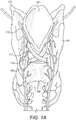
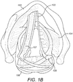
- FIG. 1A shows a coronal section view
- Figure 1B shows a transverse section view of the anatomy of a human larynx including the epiglottis 101 , thyroid cartilage 102 , vocal folds 103 , cricothyroid muscle 104 , arytenoid cartilage 105 , posterior cricoarytenoid muscle (PCAM) 106 , vocalis muscle 107 , cricoid cartilage 108 , recurrent laryngeal nerve (RLN) 109 , transverse arytenoid muscle 110 , oblique arytenoid muscle 111 , superior laryngeal nerve 112 , and hyoid bone 113 .
- PCAM posterior cricoarytenoid muscle
- RNN recurrent laryngeal nerve
- respiration frequency typically varies from 12 to 25 breaths per minute. So, for example, 20 breaths per minute result in a 3 second breath duration, with 1.5 sec inspiration, and 1.5 sec exhalation phase (assuming a 50/50 ratio).
- the breathing frequency changes depending on the physical activity.
- a more recent treatment approach to RLN injuries uses a laryngeal pacemaker that electrically stimulates (paces) the PCAM 106 during inspiration to abduct (open) the vocal folds 103 . During expiration, the vocal folds 103 relax (close) to facilitate voicing.
- the patient can vary the pacing frequency (breaths per minute) according to his physical load (at rest, normal walking, stairs, etc.) by manually switching the stimulation frequency of the pacer device, the assumption being that the human body may adapt to the artificial externally applied respiration frequency - within some locking-range.
- the patient and the laryngeal pacemaker can be described as free running oscillators at almost the same frequency, but without phase-matching (no phase-locking). Sometimes both systems will be in phase, but other times the systems will be out of phase and thus the benefit for the patient will be reduced.
- More recent second generation laryngeal pacemaker systems generate a stimulation trigger signal to synchronize the timing of stimulation of the pacemaker to the respiration cycle of the patient.
- the stimulation trigger signal defines a specific time point during the respiration cycle to initiate stimulation of the target neural tissue.
- the time point may specifically be the start or end of the inspiratory or expiratory phase of breathing, a breathing pause, or any other defined time point.
- respiration sensors include, for example, various microphones, accelerometer sensors, and pressure sensors (positioned in the pleura gap).
- EMG Electromyogram
- FIG. 2 shows one embodiment of such a laryngeal pacemaker system with a processor 201 that receives a respiration signal from a respiration sensor 202 implanted in the parasternal muscle that detects respiration activity in the implanted patient.
- a three-axis acceleration movement sensor also is located within the housing of the processor 201 and generates a movement signal.
- the processor 201 Based on the respiration signal, the processor 201 generates a respiration pacing signal that is synchronized with the detected respiration activity and delivers the pacing signal via a processor lead to a stimulating electrode 203 implanted in the target respiration neural tissue to promote breathing of the implanted patient.
- US 2015/283382 A1 discloses a laryngeal pacing system for a recipient with impaired breathing with an implantable stimulation electrode for delivering the respiration stimulation signals and a triaxial accelerometer, further comprising a pacing processor being implanted in the patient.
- Embodiments of the present invention are directed to a laryngeal pacing system for a recipient patient with impaired breathing.
- a laryngeal pacemaker is configured for external placement on skin of a patient at a sternum location and configured to produce respiration stimulation signals.
- An implantable stimulation electrode is configured for delivering the respiration stimulation signals from the laryngeal pacemaker to adjacent target neural tissue for vocal fold abduction during respiration of the recipient patient.
- a respiration sensor includes a flexible skin-transferrable printed tattoo electrode having a tetrapolar configuration for impedance pneumography measurement to produce a sensed respiration signal for the laryngeal pacemaker.
- a triaxial accelerometer is configured to produce a body motion signal for the laryngeal pacemaker that reflects energy expenditure of the recipient patient.
- the flexible skin-transferrable printed tattoo electrode (PTE) is configured for transfer and release by guided placement from a sensor applicator to a fixed skin location at the angulus sterni of the recipient patient.
- the laryngeal pacemaker is configured to interpret the body motion signal and the sensed respiration signal to make a real time determination of respiratory phase and frequency for adaptively adjusting the respiration stimulation signals accordingly.
- the laryngeal pacemaker may include an outer surface with sensor contacts configured to directly connect to the PTE for coupling the sensed respiration signal from the respiration sensor to the laryngeal pacemaker.
- the triaxial accelerometer may be integrated into the respiration sensor.
- the printed tattoo electrode may be formed from Tattoo Conductive Polymer Nanosheets for Skin-Contact Applications.
- the respiration sensor also may include a center support ring configured to mechanically engage the respiration sensor with the laryngeal pacemaker.
- the respiration sensor may be configured for transfer and release using a water-based transfer mechanism.
- a semi-rigid support layer configured to provide mechanical support to the printed tattoo electrode and configured to release a wetting layer of water when mechanically pressed.
- Such a support layer may include multiple water-holding sub-divisions, or just a single water-holding sub-division.
- the respiration sensor may be adapted to cooperate with the sensor applicator to provide positioning feedback information when the respiration sensor is placed at the fixed skin location.
- RLN stimulation is triggered in phase with the true real-time respiration activity by using a respiration sensor that tracks the instantaneous respiration phase and frequency, communicates it to the electronics of the laryngeal pacemaker which adaptively adjusts the respiration stimulation signals accordingly.
- a respiration sensor is placed and coupled close to an external portion of the system, i.e. the processor device, which is easy to replace by other identical sensor means. In particular, patients can properly locate and attach the respiration sensor on their own without need of professional assistance.
- the respiration sensor of the present invention together with proper placement yields a very accurate estimation of the onset of the respiratory phase to which a stimulation signal has to be correlated. Unlike many prior art sensor systems, a particular phase of the respiratory cycle (e.g. the onset) can be reliably detected and not just the overall respiratory rate.
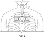
- FIG. 3 shows an example of a laryngeal pacemaker arrangement with respect to patient anatomy according to an embodiment of the present invention which is configured to provide a reliable respiration signal that reflects real-time instantaneous respiration phase and frequency.
- a laryngeal pacemaker 301 is configured for external placement on the skin of the patient at as shown in Fig. 3 at the angulus sterni of the patient, and is configured to produce respiration stimulation signals.
- There is an internal implant portion of the system at that location which includes a holding magnet that cooperates with a corresponding holding magnet in the external laryngeal processor 301 to hold the latter in place.
- the angulus sterni location is advantageous because of the ideal flat shape of the bone there, and because there is a low percentage of fat in the underlying skin layer.
- the thickness of the underlying pectoralis muscle decreases dramatically at the angulus sterni, and the bone there is not part of any joint that might be subject to roll, pitch and yaw. This therefore represents a stable position during periods of high body movement.
- the width of the manubrium sterni depends on the sex of the subject, but an average width of 5.5 cm can be assumed. That means that changes in the lung impedance due to respiration can be easily measured at the manubrium sterni sides, if at least 5.5 cm distance is given between sensing electrodes located left and right of the angulus sterni.
- the angulus sterni is an ideal placement for measurement of bio-impedance as discussed further below since motion induced artifacts are considerably reduced. We have identified this position as the best one for measuring reliably an inspiratory signal in the way described below.
- an implantable stimulation electrode 203 as known in the art is configured for delivering the respiration stimulation signals from the laryngeal pacemaker 301 to adjacent target neural tissue (e.g., RLN) for vocal fold abduction during respiration of the patient.
- the respiration sensor 300 is configured to produce a sensed respiration signal for the laryngeal pacemaker 301 .
- the respiration sensor 300 also is configured for transfer and release by guided placement from a sensor applicator to a fixed skin location at the angulus sterni.
- the laryngeal pacemaker 301 interprets the body motion signal and the sensed respiration signal to make a real time determination of respiratory phase and frequency for adaptively adjusting the respiration stimulation signals accordingly.
- a triaxial accelerometer may be integrated into the respiration sensor 300 or the laryngeal pacemaker 301 to produce a body motion signal for the laryngeal pacemaker 301 that reflects energy expenditure of the patient.
- the body motion signal also can be used for optimizing battery consumption, and the attending body activity detection can be used to determine steady or low movement situations when the laryngeal pacemaker 301 can switch to a paced stimulation to save power.
- the laryngeal pacemaker 301 may be configured to compute Energy Expenditure (EE) as a function of x-, y- and z-axis acceleration signals.
- EE Energy Expenditure
- the tri-axial acceleration body motion signal reflects both a gravitational component and a body motion component, and so the laryngeal pacemaker 301 may need to initially filter and process the body motion signal to extrapolate only the body motion information. Then a Signal Vector Magnitude (SVM) can be computed and compared to pre-determined thresholds that correspond to different body activities. This activity determination can be used to adjust the parameters of the adaptive filtering and peak detection of the bio-impedance signal explained below.
- SVM Signal Vector Magnitude
- the respiration sensor 300 includes a center support ring 410 that is configured to mechanically engage the respiration sensor 300 with the laryngeal pacemaker 301 .
- the specific shape of the support ring 401 can vary to accommodate different specific design features of the housing of the laryngeal pacemaker 301 .
- Enclosed with the support ring 410 are one or more sensor contacts 440 that are configured to provide a direct electrical connection to corresponding sensor contacts 460 on the bottom surface 470 of the housing of the laryngeal pacemaker 301 when it is enclosed within the support ring 410 .
- the respiration sensor 300 includes inner sensing contacts 520 and outer excitation contacts 510 that are connected to the sensor contacts 440 by electrically isolated conductive paths 530 made e.g. of gold or other conductive material.
- the inner sensing contacts 520 and outer excitation contacts 510 are arranged in a tetrapolar configuration for impedance pneumography (IPG) measurement of changes in transthoracic electrical impedance as shown in Figure 6A .
- IPG impedance pneumography
- Excitation current flows from the outer excitation contacts 510 (A to D), whereas inner sensing contacts 520 (B and C) measure the corresponding difference of voltage.
- the electrode-skin interface implicates various considerations with regard to recording biological signals. These include the fact that high skin impedance can result in poor signal detection. In addition, relative movement between the electrode and the skin produces motion artifacts. Motion artifacts result from a change in electrical properties of the skin-electrode interface as shown in Figure 6B .
- the so-called half-cell potential VH (which results from the charge of the metal-electrolyte interface) can be modelled as a current source and parallel resistor Rt.
- Resistor Rs represents the stratum comeum, which is an outer skin dielectric layer that decreases the quality of the acquired bio-signal.
- the half-cell potential VH arises because the current I flows through the resistive extracellular medium Rt.
- Motion artifacts therefore appear as a potential change due to the current I flowing through the changing resistance Rt which can increase or decrease depending on the nature of the force applied.
- the relative movement of the electrode with respect to skin can further change the voltage VH. Filtering out and/or reducing motion artifacts is very important.
- Wet gel electrodes are commonly used to improve or stabilize the sensing contact and reduce skin impedance by increasing the conductive of the stratum corneum layer. Any mechanical disturbances caused by relative motion between the electrode and the skin are damped by the intervening gel layer, and their effect on the signal is limited. They can be schematized as almost resistive impedance, whose value is in the range of few decades of Ohms.
- the respiration sensor 300 is made from ultrathin and ultra-conformable flexible nanosheets composed of conducting polymer complex poly (PEDOT:PSS) that form a printed tattoo electrode 420 which provide ultra-conformability on a complex surface such as skin.
- the respiration sensor 300 specifically may form Tattoo Conductive Polymer Nanosheets for Skin-Contact Applications temporary printed tattoos that are transferred and released to the skin location, thereby overcoming the issue with lack of conformability and poor adhesion that usually occurs with standard dry electrodes.
- an electrode liner 430 On the underside of the respiration sensor 300 is an electrode liner 430 that is removed when applying the respiration sensor 300 to the skin.
- the respiration sensor 300 is released to the skin by gently and uniformly rubbing a wet finger (or any other equivalent means) over the top surface of the respiration sensor 300 . The consequent release of the respiration sensor 300 to the skin will occur in a few seconds.
- the support layer 700 includes an inner water pocket 710 and two outer water pockets 720 that form an integrated water release system to release a wetting layer of water when mechanically pressed to further promote transfer of the printed tattoo electrode 420 to the skin.
- the water pockets 710 and 720 are configured to break and release water when finger pressure is applied. After the water has been uniformly released to the underlying printed tattoo electrode 420 , the support layer 700 can be torn off as shown by the arrows. While the support layer shown in Figures 7A-7B includes a plurality of water pockets, an embodiment as shown in Figure 8 could have a support layer 800 with a single water pocket 810 .
- Figure 9 shows the bottom surface 900 of a laryngeal pacemaker with sensor contacts 910 in the form of multiple concentric rings. This arrangement would allow the laryngeal pacemaker to freely rotate about its axis while still be able to acquire the sensed respiration signal.
- the laryngeal pacemaker 301 performs adaptive filtering processing of the bio-impedance sensed respiration signal from the respiration sensor 300 in combination with the body motion activity determination from the accelerometer signal.
- the sensed respiration signal typically is defined in the range [0.1 Hz ⁇ 1 Hz] in dependence on the body activity occurring.
- the adaptive filtering of the sensed respiration signal is directed achieving the greatest possible Signal to Noise Ratio (SNR) over the different real-life situations that the patient may encounter.
- SNR Signal to Noise Ratio
- the adaptive filtering may be based on a Least Mean Square Filter (LMS) approach.
- LMS Least Mean Square Filter
- the sensed respiration signal can be filtered in real time without any further external input.
- the filtered sensed respiration signal is then used to detect the onset of the respiration as shown in Figure 10 .
- the first row waveform in Fig. 10 shows the raw bio-impedance and reference signals overlapped.
- the reference signal is acquired by a thermistor that the patient wears during the acquisition together with the sensor and electrodes measuring the bio-impedance.
- the second and third row waveforms show the filtered bio-impedance and reference signal respectively.
- the respiration onsets of the signals are shown by the vertical lines on the waveforms.
- Accuracy detection is computed together with signal correlation in the histogram plots on the left side of Fig. 10 (100% and 94% respectively for this particular experiment).
- Respiration onset detection is considered successful when the onset in the bio-impedance signal is detected within a maximum delay of 500 msec from the true onset shown in the reference signal.
- a Bayesian peak validation algorithm can later be used to identify the true peaks based on a Kalman filter.
- Embodiments of a laryngeal pacemaker and respiration sensor as described above allow for real time stimulation signals to the target neural tissue that can be triggered by the real time respiratory signal rather than on the base of pre-determined pacing.
- the described respiration sensor is not invasive and can be embedded/integrated into the housing of the laryngeal pacemaker without increasing its external dimensions.
- long term monitoring can be provided since the set up the printed tattoo electrode overcomes the issues of wet gel electrodes and can provide ultra-conformability and adhesion on the skin for up to three days.
- the extremely reduced thickness of the tattoo electrode and the absence of adhesive material also provides for increased comfort and wearability of the respiration sensor.
- the tetrapolar electrode configuration together with the placement on the chest at the angulus sterni provides increased robustness to motion artifacts.
- the respiration sensor technology described above that is based on Printed Tattoo Electrodes (PTE) can provide ultra-conformability on a complex surface like skin. Their transfer and release as temporary tattoos overcomes the issue with lack of conformability and poor adhesion which usually occurs with standard dry electrodes. And the general field of flexible and skin-transferable sensors is itself receiving ever greater interest due to the potential of developing highly integrated sensors for monitoring vital signs that are portable and not overly invasive.
- PTE Printed Tattoo Electrodes
- embodiments of the present invention include a sensor applicator configured to provide reliable, easy and effective placement and release of the sensor by means of a user-friendly design that avoids mis-application.
- the transfer and release of the PTE sensor can be performed by the patients themselves without needing additional assistance of a trained expert.
- the sensor applicator guides the patient to correctly place the PTE sensor in the desired correspondence with the angulus sterni in an exactly horizontal positioning, and the sensor applicator can provide feedback to the patient on whether or not the transfer and release process occurred correctly.
- Embodiments of such a sensor applicator can be used for the placement of any flexible and skin-transferable sensor.
- Figures 11A-11B show different views of a sensor applicator 1100 according to an embodiment of the present invention. Specific sensor applicator arrangements may make use of active electronics, passive electronics only, or no electronics at all.
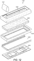
- Figure 12 shows an exploded view of different structural elements the sensor applicator 1100 .
- a pressure roller 1201 fits and slides within an upper housing 1202 .
- Lower housing frame 1204 and bottom surface 1205 fit together to form a holding receptacle configured to contain a fluid storage sponge 1203 .
- fluid storage sponge 1203 may be made of sponge material or any other equivalent material that can absorb and hold a small amount of release fluid such as water.
- the PTE sensor 1206 is inserted into the bottom of the sensor applicator 1100 .
- Pressure roller 1201 fits within two sliding tracks located within the upper housing 1202 to slide freely along the longitudinal axis of the upper housing 1202 .
- the bottom side of the upper housing 1202 is a flexible pressure surface on top of which the pressure roller 1201 can be pushed along its displacement trajectory.
- the pressure surface of the upper housing 1202 may be a simple water resistant foil, or in more advanced embodiments, it may be made of a piezo-chromic material that exhibits a reversible color change under pressure effect. Reversible piezo-chromic materials with memory-effect change color at some initial activation pressure PI, and then recover the original color when the applied pressure drops below second recovery pressure P2.
- the difference between these two pressures P1 and P2 defines the memory effect and allows specification of the history of the material (i.e. if the material has exceeded a threshold of pressure).
- the upper housing 1202 and/or the lower housing frame 1204 may incorporate signal acquisition sensors configured to receive the sensed ECG signal from the released PTE sensor 1206 when it is applied to the patient's skin.
- Simple electronics within the sensor applicator 1100 then can perform a signal level thresholding and determine whether or not an acceptable signal has been detected. If acceptable, a feedback LED on the body of the sensor applicator 1100 turns green to confirm the successful release of the PTE sensor 1206 .
- Lower housing frame 1204 and bottom surface 1205 fit may be structurally separate pieces configured to fit together, or they may be integrated together into a single structural element.
- the bottom surface 1205 is configured to securely hold the PTE sensor 1206 while it is within the sensor applicator 1100 .
- the bottom surface 1205 may incorporate one or more locking clips arranged to move cooperatively or independently, for example, along a perpendicular axis of the bottom surface 1205 .
- Such locking clips are configured to provide appropriate support to avoid the PTE sensor 1206 inadvertently slipping away from the bottom surface 1205 .
- the locking clips can have a saw tooth profile that enhances the security of the PTE sensor 1206 to the bottom surface 1205 .
- Figures 13A-13D show various aspects in using a sensor applicator according to an embodiment of the present invention.
- the sensor applicator 1100 is disassembled so that the fluid storage sponge 1203 needs to be inserted into the lower housing frame 1204 as shown by the thick arrow, and then, as shown by Fig. 13B , the upper housing 1202 lower housing frame 1204 are coupled together.
- the sensor applicator 1100 can then be inverted and the PTE sensor 1206 can be inserted into the lower housing frame 1204 against the bottom surface 1205 as shown in Fig. 13C .
- the electrode liner 430 is removed.
- the assembled sensor applicator 1100 is ready to be placed on the chest of the patient.
- Correct placement of the assembled sensor applicator 1100 at the angulus sterni can be confirmed by one or more LEDs in the side of the sensor applicator 1100 .
- a magnetic sensor within the sensor applicator 1100 can be configured to detect proximity of the device to the implanted magnet at the angulus sterni location, and first positioning LED would then turn green.
- the PTE sensor needs to be placed as closely as possible to horizontal.
- the sensor applicator 1100 may also contain a sensing gyroscope configured to detect when the device is positioned horizontally within some pre-determined angle of tolerance, and a second positioning LED would then turn green confirming the horizontal position.
- the patient is holding the loaded sensor applicator 1100 on the chest with one hand, and the other hand can then move the pressure roller 1201 within the sensor applicator 1100 to activate the water-based release mechanism.
- the release mechanism may be further promoted if the patient also pushes down on the pressure roller 1201 .
- Activation of the pressure roller 1201 squeezes the fluid storage sponge 1203 within the sensor applicator 1100 , causing a uniform water release onto the PTE sensor 1206 that transfers it to the skin.
- the specific release feedback mechanism (as discussed above) the patient gets release feedback on whether or not the release movement needs to be repeated. For example, the confirming color change of the pressure surface of the upper housing 1202 or a third release LED turning green confirms a correct conclusion of the sensor application process.
- specific embodiments of the sensor applicator 1100 may incorporate active electronic elements such as a magnetic sensor, a gyroscope, and/or sensor signal threshold detection logic that are configured to support the patient in the correct placement of the device on the chest.
- specific embodiments of the sensor applicator 1100 may in addition or alternative use passive elements for one or more of the same purposes.
- the proximity of the sensor applicator 1100 to the implanted magnet may be detected by placing another magnet within the applicator at its center.
- Horizontal placement of the sensor applicator 1100 may be achieved by using a spirit level in the longitudinal side of the device.
- the piezo-chromatic effect described above for release feedback already represents a passive approach.
- Embodiments of a sensor applicator as described above reflect a user-friendly design that is easy and intuitive to use. This promotes the precision and reliability of the transfer and release of the sensor device by the patients themselves without the need of an additional expert. Moreover, a sensor applicator with a sponge-based water release mechanism may be even better performing than the breakable water pocket solutions described earlier. In addition, a respiration that is applied by a sensor applicator as just described may avoid the need for incorporating a support ring into the sensor device. That would reduce the cost per unit of the sensor device.
- Embodiments of the invention may be implemented in part in any conventional computer programming language such as VHDL, SystemC, Verilog, ASM, etc.
- Alternative embodiments of the invention may be implemented as pre-programmed hardware elements, other related components, or as a combination of hardware and software components.
- Embodiments can be implemented in part as a computer program product for use with a computer system.
- Such implementation may include a series of computer instructions fixed either on a tangible medium, such as a computer readable medium (e.g., a diskette, CD-ROM, ROM, or fixed disk) or transmittable to a computer system, via a modem or other interface device, such as a communications adapter connected to a network over a medium.
- the medium may be either a tangible medium (e.g., optical or analog communications lines) or a medium implemented with wireless techniques (e.g., microwave, infrared or other transmission techniques).
- the series of computer instructions embodies all or part of the functionality previously described herein with respect to the system.
- Such computer instructions can be written in a number of programming languages for use with many computer architectures or operating systems. Furthermore, such instructions may be stored in any memory device, such as semiconductor, magnetic, optical or other memory devices, and may be transmitted using any communications technology, such as optical, infrared, microwave, or other transmission technologies. It is expected that such a computer program product may be distributed as a removable medium with accompanying printed or electronic documentation (e.g., shrink wrapped software), preloaded with a computer system (e.g., on system ROM or fixed disk), or distributed from a server or electronic bulletin board over the network (e.g., the Internet or World Wide Web). Of course, some embodiments of the invention may be implemented as a combination of both software (e.g., a computer program product) and hardware. Still other embodiments of the invention are implemented as entirely hardware, or entirely software (e.g., a computer program product).
Landscapes
- Health & Medical Sciences (AREA)
- Radiology & Medical Imaging (AREA)
- Animal Behavior & Ethology (AREA)
- Engineering & Computer Science (AREA)
- Biomedical Technology (AREA)
- Nuclear Medicine, Radiotherapy & Molecular Imaging (AREA)
- Veterinary Medicine (AREA)
- Life Sciences & Earth Sciences (AREA)
- Pulmonology (AREA)
- General Health & Medical Sciences (AREA)
- Public Health (AREA)
- Physiology (AREA)
- Cardiology (AREA)
- Heart & Thoracic Surgery (AREA)
- Measurement Of The Respiration, Hearing Ability, Form, And Blood Characteristics Of Living Organisms (AREA)
Claims (10)
- Kehlkopfschrittmachersystem für einen Patienten mit beeinträchtigter Atmung, wobei das System folgendes aufweist:einen Kehlkopfschrittmacher (301), der zur externen Platzierung auf der Haut eines Patienten an einer Stelle des Brustbeins eingerichtet ist und dazu eingerichtet ist, Atmungsstimulationssignale zu erzeugen;eine implantierbare Stimulationselektrode (203), die dazu eingerichtet ist, die Atmungsstimulationssignale von dem Kehlkopfschrittmacher an benachbartes neurales Zielgewebe zur Stimmlippenabduktion während der Atmung des Empfängerpatienten zu liefern;einen triaxialen Beschleunigungsmesser, der dazu eingerichtet ist, ein Körperbewegungssignal für den Kehlkopfschrittmacher zu erzeugen, das den Energieverbrauch des Empfängerpatienten widerspiegelt;einen Atmungssensor (300), der eine flexible, auf die Haut übertragbare, gedruckte Tattoo-Elektrode mit einer tetrapolaren Konfiguration zur Impedanzpneumographie-Messung aufweist, um ein erfasstes Atmungssignal für den Kehlkopfschrittmacher zu erzeugen;wobei der Atmungssensor dazu eingerichtet ist, durch geführte Platzierung von einem Sensorapplikator an eine feste Hautstelle am Angulus sterni des Empfängerpatienten übertragen und freigegeben zu werden; undwobei der Kehlkopfschrittmacher dazu eingerichtet ist, das Körperbewegungssignal und das erfasste Atmungssignal zu interpretieren, um eine Echtzeitbestimmung der Atmungsphase und -frequenz vorzunehmen, um die Atmungsstimulationssignale entsprechend adaptiv anzupassen.
- Kehlkopfschrittmachersystem nach Anspruch 1, wobei der Kehlkopfschrittmacher eine Außenfläche mit einer Vielzahl von Sensorkontakten umfasst, die dazu eingerichtet sind, direkt mit dem Atmungssensor verbunden zu werden, um das erfasste Atmungssignal vom Atmungssensor mit dem Kehlkopfschrittmacher zu koppeln.
- Kehlkopf-Schrittmachersystem nach Anspruch 1, wobei der triaxiale Beschleunigungsmesser in den Kehlkopf-Schrittmacher integriert ist.
- Kehlkopfschrittmachersystem nach Anspruch 1, wobei die gedruckte Tattoo-Elektrode leitfähige Polymer-Nanoschichten aufweist.
- Kehlkopfschrittmachersystem nach Anspruch 1, wobei der Atmungssensor ferner einen zentralen Stützring aufweist, der dazu eingerichtet ist, den Atmungssensor mechanisch mit dem Kehlkopfschrittmacher zu verbinden.
- Kehlkopfschrittmachersystem nach Anspruch 1, wobei der Atmungssensor für die Übertragung und Freigabe unter Verwendung eines Übertragungsmechanismus auf Wasserbasis eingerichtet ist.
- Kehlkopfschrittmachersystem nach Anspruch 6, wobei der Atmungssensor ferner eine halbstarre Trägerschicht aufweist, die so eingerichtet ist, dass sie die gedruckte Tattoo-Elektrode mechanisch stützt und so eingerichtet ist, dass sie bei mechanischem Druck eine Benetzungsschicht aus Wasser abgibt.
- Kehlkopfschrittmachersystem nach Anspruch 7, wobei die Trägerschicht eine Vielzahl von wasserhaltenden Unterteilungen umfasst.
- Kehlkopfschrittmachersystem nach Anspruch 7, wobei die Trägerschicht eine einzelne wasserhaltende Unterteilung umfasst.
- Kehlkopf-Schrittmachersystem nach Anspruch 1, wobei der Atmungssensor dazu ausgelegt ist, mit dem Sensorapplikator zusammenzuarbeiten, um eine Positionsrückmeldung zu liefern, wenn der Atmungssensor an der festen Hautstelle platziert ist.
Applications Claiming Priority (2)
| Application Number | Priority Date | Filing Date | Title |
|---|---|---|---|
| US201662426647P | 2016-11-28 | 2016-11-28 | |
| PCT/US2017/063225 WO2018098409A1 (en) | 2016-11-28 | 2017-11-27 | Respiration monitoring sensor for a laryngeal pacemaker |
Publications (3)
| Publication Number | Publication Date |
|---|---|
| EP3544673A1 EP3544673A1 (de) | 2019-10-02 |
| EP3544673A4 EP3544673A4 (de) | 2020-07-29 |
| EP3544673B1 true EP3544673B1 (de) | 2021-11-17 |
Family
ID=62195673
Family Applications (1)
| Application Number | Title | Priority Date | Filing Date |
|---|---|---|---|
| EP17873289.7A Active EP3544673B1 (de) | 2016-11-28 | 2017-11-27 | Atemüberwachungssensor für einen kehlkopfschrittmacher |
Country Status (5)
| Country | Link |
|---|---|
| US (4) | US20190344072A1 (de) |
| EP (1) | EP3544673B1 (de) |
| CN (1) | CN109982745B (de) |
| AU (1) | AU2017363345B2 (de) |
| WO (1) | WO2018098409A1 (de) |
Families Citing this family (4)
| Publication number | Priority date | Publication date | Assignee | Title |
|---|---|---|---|---|
| AU2020322472B2 (en) * | 2019-07-31 | 2023-12-21 | Med-El Elektromedizinische Geraete Gmbh | Printed tattoo electrode respiration sensor for laryngeal pacemakers |
| EP4146080A1 (de) * | 2020-05-08 | 2023-03-15 | W.L. Gore & Associates, Inc. | Transkutaner schallsensor |
| KR20260018059A (ko) * | 2023-05-18 | 2026-02-06 | 더 리젠츠 오브 더 유니버시티 오브 미시건 | 근육 및 피부 내 전극을 포함하는 근육 커프 및 피부 재생 말초 신경 인터페이스(rpni) |
| CN119656472A (zh) * | 2024-12-09 | 2025-03-21 | 南京宽诚科技有限公司 | 一种基于生物反馈的呼吸治疗系统及方法 |
Family Cites Families (17)
| Publication number | Priority date | Publication date | Assignee | Title |
|---|---|---|---|---|
| US5111814A (en) * | 1990-07-06 | 1992-05-12 | Thomas Jefferson University | Laryngeal pacemaker |
| JP2004524125A (ja) * | 2001-04-05 | 2004-08-12 | メド−エル・エレクトロメディツィニシェ・ゲラーテ・ゲーエムベーハー | 両側声帯自律麻痺のためのペースメーカー |
| WO2006102591A2 (en) * | 2005-03-24 | 2006-09-28 | Vanderbilt University | Respiratory triggered, bilateral laryngeal stimulator to restore normal ventilation in vocal fold paralysis |
| US7801603B2 (en) * | 2006-09-01 | 2010-09-21 | Cardiac Pacemakers, Inc. | Method and apparatus for optimizing vagal nerve stimulation using laryngeal activity |
| US9072899B1 (en) * | 2009-09-04 | 2015-07-07 | Todd Nickloes | Diaphragm pacemaker |
| US8983610B2 (en) * | 2009-11-18 | 2015-03-17 | Case Western Reserve University | Hybrid method for modulating upper airway function in a subject |
| US10441185B2 (en) * | 2009-12-16 | 2019-10-15 | The Board Of Trustees Of The University Of Illinois | Flexible and stretchable electronic systems for epidermal electronics |
| CN103415318B (zh) * | 2010-12-29 | 2016-08-24 | 心脏起搏器股份公司 | 使用电阻抗的神经心脏治疗 |
| WO2014025430A2 (en) * | 2012-05-10 | 2014-02-13 | The Regents Of The University Of California | Wearable electrochemical sensors |
| CN109939348B (zh) * | 2013-06-17 | 2024-03-01 | 尼科索亚股份有限公司 | 植入物单元递送工具 |
| US20150283382A1 (en) * | 2014-04-04 | 2015-10-08 | Med-El Elektromedizinische Geraete Gmbh | Respiration Sensors For Recording Of Triggered Respiratory Signals In Neurostimulators |
| AU2015253735B2 (en) * | 2014-04-28 | 2018-03-01 | Med-El Elektromedizinische Geraete Gmbh | Respiration sensors for recording of triggered respiratory signals in neurostimulators |
| CN104353167B (zh) * | 2014-11-28 | 2017-03-29 | 山东大学齐鲁医院 | 一种具有体外膈肌起搏功能的呼气正压通气面罩 |
| WO2016090189A1 (en) * | 2014-12-03 | 2016-06-09 | The Regents Of The University Of California | Non-invasive and wearable chemical sensors and biosensors |
| WO2016181958A1 (ja) * | 2015-05-11 | 2016-11-17 | 学校法人早稲田大学 | 電子デバイスおよびその製造方法 |
| US11567028B2 (en) * | 2015-11-29 | 2023-01-31 | Ramot At Tel-Aviv University Ltd. | Sensing electrode and method of fabricating the same |
| AU2020322472B2 (en) * | 2019-07-31 | 2023-12-21 | Med-El Elektromedizinische Geraete Gmbh | Printed tattoo electrode respiration sensor for laryngeal pacemakers |
-
2017
- 2017-11-27 EP EP17873289.7A patent/EP3544673B1/de active Active
- 2017-11-27 WO PCT/US2017/063225 patent/WO2018098409A1/en not_active Ceased
- 2017-11-27 CN CN201780072464.5A patent/CN109982745B/zh active Active
- 2017-11-27 US US16/347,637 patent/US20190344072A1/en not_active Abandoned
- 2017-11-27 AU AU2017363345A patent/AU2017363345B2/en active Active
-
2021
- 2021-08-23 US US17/409,276 patent/US20210379371A1/en not_active Abandoned
-
2023
- 2023-10-10 US US18/378,379 patent/US20240042200A1/en not_active Abandoned
-
2025
- 2025-12-19 US US19/426,569 patent/US20260108734A1/en active Pending
Also Published As
| Publication number | Publication date |
|---|---|
| US20240042200A1 (en) | 2024-02-08 |
| US20210379371A1 (en) | 2021-12-09 |
| US20190344072A1 (en) | 2019-11-14 |
| WO2018098409A1 (en) | 2018-05-31 |
| AU2017363345B2 (en) | 2020-04-16 |
| CN109982745B (zh) | 2023-06-02 |
| EP3544673A4 (de) | 2020-07-29 |
| AU2017363345A1 (en) | 2019-07-11 |
| EP3544673A1 (de) | 2019-10-02 |
| CN109982745A (zh) | 2019-07-05 |
| US20260108734A1 (en) | 2026-04-23 |
Similar Documents
| Publication | Publication Date | Title |
|---|---|---|
| US20260108734A1 (en) | Respiration Monitoring Sensor for a Laryngeal Pacemaker | |
| US12029903B2 (en) | Systems and methods for strengthening a respiratory muscle | |
| US12070601B2 (en) | Stimulation system for exercising diaphragm and method of operation thereof | |
| JP2020529264A (ja) | 血管内カテーテルの配置及び/または神経刺激のためのシステムならびに方法 | |
| US20170043168A1 (en) | Acceleration Sensors For Recording Of Triggered Respiratory Signals In Neurostimulators | |
| EP3490663B1 (de) | Respiratorisch ausgelöste parasternale elektromyografische aufzeichnung in neurostimulatoren | |
| US9550059B2 (en) | Respiration sensors for recording of triggered respiratory signals in neurostimulators | |
| US20260027359A1 (en) | Devices and methods for adjusting and tracking respiration-stimulating electrodes | |
| EP4003501B1 (de) | Gedruckter tattoo-elektroden-respirationssensor für kehlkopfschrittmacher | |
| JP2010214024A (ja) | 呼吸運動支援装置 | |
| Kathiresan et al. | A review of abdominal muscle stimulation for patients with spinal cord injury |
Legal Events
| Date | Code | Title | Description |
|---|---|---|---|
| STAA | Information on the status of an ep patent application or granted ep patent |
Free format text: STATUS: THE INTERNATIONAL PUBLICATION HAS BEEN MADE |
|
| PUAI | Public reference made under article 153(3) epc to a published international application that has entered the european phase |
Free format text: ORIGINAL CODE: 0009012 |
|
| STAA | Information on the status of an ep patent application or granted ep patent |
Free format text: STATUS: REQUEST FOR EXAMINATION WAS MADE |
|
| 17P | Request for examination filed |
Effective date: 20190507 |
|
| AK | Designated contracting states |
Kind code of ref document: A1 Designated state(s): AL AT BE BG CH CY CZ DE DK EE ES FI FR GB GR HR HU IE IS IT LI LT LU LV MC MK MT NL NO PL PT RO RS SE SI SK SM TR |
|
| AX | Request for extension of the european patent |
Extension state: BA ME |
|
| RIN1 | Information on inventor provided before grant (corrected) |
Inventor name: DENK, CHRISTIAN Inventor name: POSCHL, CHRISTIANE Inventor name: SABA, RAMI Inventor name: LOMBARDI, ALBERTO Inventor name: SANTONOCITO, DANIELE Inventor name: DIEKOW, CHRISTIAN Inventor name: MAULE, FRANCESCA |
|
| DAV | Request for validation of the european patent (deleted) | ||
| DAX | Request for extension of the european patent (deleted) | ||
| A4 | Supplementary search report drawn up and despatched |
Effective date: 20200629 |
|
| RIC1 | Information provided on ipc code assigned before grant |
Ipc: A61N 1/05 20060101ALI20200623BHEP Ipc: A61N 1/36 20060101AFI20200623BHEP |
|
| GRAP | Despatch of communication of intention to grant a patent |
Free format text: ORIGINAL CODE: EPIDOSNIGR1 |
|
| STAA | Information on the status of an ep patent application or granted ep patent |
Free format text: STATUS: GRANT OF PATENT IS INTENDED |
|
| INTG | Intention to grant announced |
Effective date: 20210602 |
|
| GRAS | Grant fee paid |
Free format text: ORIGINAL CODE: EPIDOSNIGR3 |
|
| GRAA | (expected) grant |
Free format text: ORIGINAL CODE: 0009210 |
|
| STAA | Information on the status of an ep patent application or granted ep patent |
Free format text: STATUS: THE PATENT HAS BEEN GRANTED |
|
| AK | Designated contracting states |
Kind code of ref document: B1 Designated state(s): AL AT BE BG CH CY CZ DE DK EE ES FI FR GB GR HR HU IE IS IT LI LT LU LV MC MK MT NL NO PL PT RO RS SE SI SK SM TR |
|
| REG | Reference to a national code |
Ref country code: GB Ref legal event code: FG4D |
|
| REG | Reference to a national code |
Ref country code: DE Ref legal event code: R096 Ref document number: 602017049606 Country of ref document: DE |
|
| REG | Reference to a national code |
Ref country code: IE Ref legal event code: FG4D |
|
| REG | Reference to a national code |
Ref country code: AT Ref legal event code: REF Ref document number: 1447554 Country of ref document: AT Kind code of ref document: T Effective date: 20211215 |
|
| REG | Reference to a national code |
Ref country code: LT Ref legal event code: MG9D |
|
| REG | Reference to a national code |
Ref country code: NL Ref legal event code: MP Effective date: 20211117 |
|
| REG | Reference to a national code |
Ref country code: AT Ref legal event code: MK05 Ref document number: 1447554 Country of ref document: AT Kind code of ref document: T Effective date: 20211117 |
|
| PG25 | Lapsed in a contracting state [announced via postgrant information from national office to epo] |
Ref country code: RS Free format text: LAPSE BECAUSE OF FAILURE TO SUBMIT A TRANSLATION OF THE DESCRIPTION OR TO PAY THE FEE WITHIN THE PRESCRIBED TIME-LIMIT Effective date: 20211117 Ref country code: LT Free format text: LAPSE BECAUSE OF FAILURE TO SUBMIT A TRANSLATION OF THE DESCRIPTION OR TO PAY THE FEE WITHIN THE PRESCRIBED TIME-LIMIT Effective date: 20211117 Ref country code: FI Free format text: LAPSE BECAUSE OF FAILURE TO SUBMIT A TRANSLATION OF THE DESCRIPTION OR TO PAY THE FEE WITHIN THE PRESCRIBED TIME-LIMIT Effective date: 20211117 Ref country code: BG Free format text: LAPSE BECAUSE OF FAILURE TO SUBMIT A TRANSLATION OF THE DESCRIPTION OR TO PAY THE FEE WITHIN THE PRESCRIBED TIME-LIMIT Effective date: 20220217 Ref country code: AT Free format text: LAPSE BECAUSE OF FAILURE TO SUBMIT A TRANSLATION OF THE DESCRIPTION OR TO PAY THE FEE WITHIN THE PRESCRIBED TIME-LIMIT Effective date: 20211117 |
|
| PG25 | Lapsed in a contracting state [announced via postgrant information from national office to epo] |
Ref country code: IS Free format text: LAPSE BECAUSE OF FAILURE TO SUBMIT A TRANSLATION OF THE DESCRIPTION OR TO PAY THE FEE WITHIN THE PRESCRIBED TIME-LIMIT Effective date: 20220317 Ref country code: SE Free format text: LAPSE BECAUSE OF FAILURE TO SUBMIT A TRANSLATION OF THE DESCRIPTION OR TO PAY THE FEE WITHIN THE PRESCRIBED TIME-LIMIT Effective date: 20211117 Ref country code: PT Free format text: LAPSE BECAUSE OF FAILURE TO SUBMIT A TRANSLATION OF THE DESCRIPTION OR TO PAY THE FEE WITHIN THE PRESCRIBED TIME-LIMIT Effective date: 20220317 Ref country code: PL Free format text: LAPSE BECAUSE OF FAILURE TO SUBMIT A TRANSLATION OF THE DESCRIPTION OR TO PAY THE FEE WITHIN THE PRESCRIBED TIME-LIMIT Effective date: 20211117 Ref country code: NO Free format text: LAPSE BECAUSE OF FAILURE TO SUBMIT A TRANSLATION OF THE DESCRIPTION OR TO PAY THE FEE WITHIN THE PRESCRIBED TIME-LIMIT Effective date: 20220217 Ref country code: NL Free format text: LAPSE BECAUSE OF FAILURE TO SUBMIT A TRANSLATION OF THE DESCRIPTION OR TO PAY THE FEE WITHIN THE PRESCRIBED TIME-LIMIT Effective date: 20211117 Ref country code: LV Free format text: LAPSE BECAUSE OF FAILURE TO SUBMIT A TRANSLATION OF THE DESCRIPTION OR TO PAY THE FEE WITHIN THE PRESCRIBED TIME-LIMIT Effective date: 20211117 Ref country code: HR Free format text: LAPSE BECAUSE OF FAILURE TO SUBMIT A TRANSLATION OF THE DESCRIPTION OR TO PAY THE FEE WITHIN THE PRESCRIBED TIME-LIMIT Effective date: 20211117 Ref country code: GR Free format text: LAPSE BECAUSE OF FAILURE TO SUBMIT A TRANSLATION OF THE DESCRIPTION OR TO PAY THE FEE WITHIN THE PRESCRIBED TIME-LIMIT Effective date: 20220218 Ref country code: ES Free format text: LAPSE BECAUSE OF FAILURE TO SUBMIT A TRANSLATION OF THE DESCRIPTION OR TO PAY THE FEE WITHIN THE PRESCRIBED TIME-LIMIT Effective date: 20211117 |
|
| REG | Reference to a national code |
Ref country code: CH Ref legal event code: PL |
|
| PG25 | Lapsed in a contracting state [announced via postgrant information from national office to epo] |
Ref country code: SM Free format text: LAPSE BECAUSE OF FAILURE TO SUBMIT A TRANSLATION OF THE DESCRIPTION OR TO PAY THE FEE WITHIN THE PRESCRIBED TIME-LIMIT Effective date: 20211117 Ref country code: SK Free format text: LAPSE BECAUSE OF FAILURE TO SUBMIT A TRANSLATION OF THE DESCRIPTION OR TO PAY THE FEE WITHIN THE PRESCRIBED TIME-LIMIT Effective date: 20211117 Ref country code: RO Free format text: LAPSE BECAUSE OF FAILURE TO SUBMIT A TRANSLATION OF THE DESCRIPTION OR TO PAY THE FEE WITHIN THE PRESCRIBED TIME-LIMIT Effective date: 20211117 Ref country code: LU Free format text: LAPSE BECAUSE OF NON-PAYMENT OF DUE FEES Effective date: 20211127 Ref country code: EE Free format text: LAPSE BECAUSE OF FAILURE TO SUBMIT A TRANSLATION OF THE DESCRIPTION OR TO PAY THE FEE WITHIN THE PRESCRIBED TIME-LIMIT Effective date: 20211117 Ref country code: DK Free format text: LAPSE BECAUSE OF FAILURE TO SUBMIT A TRANSLATION OF THE DESCRIPTION OR TO PAY THE FEE WITHIN THE PRESCRIBED TIME-LIMIT Effective date: 20211117 Ref country code: CZ Free format text: LAPSE BECAUSE OF FAILURE TO SUBMIT A TRANSLATION OF THE DESCRIPTION OR TO PAY THE FEE WITHIN THE PRESCRIBED TIME-LIMIT Effective date: 20211117 Ref country code: BE Free format text: LAPSE BECAUSE OF NON-PAYMENT OF DUE FEES Effective date: 20211130 |
|
| REG | Reference to a national code |
Ref country code: BE Ref legal event code: MM Effective date: 20211130 |
|
| REG | Reference to a national code |
Ref country code: DE Ref legal event code: R097 Ref document number: 602017049606 Country of ref document: DE |
|
| PG25 | Lapsed in a contracting state [announced via postgrant information from national office to epo] |
Ref country code: MC Free format text: LAPSE BECAUSE OF FAILURE TO SUBMIT A TRANSLATION OF THE DESCRIPTION OR TO PAY THE FEE WITHIN THE PRESCRIBED TIME-LIMIT Effective date: 20211117 Ref country code: LI Free format text: LAPSE BECAUSE OF NON-PAYMENT OF DUE FEES Effective date: 20211130 Ref country code: CH Free format text: LAPSE BECAUSE OF NON-PAYMENT OF DUE FEES Effective date: 20211130 |
|
| PLBE | No opposition filed within time limit |
Free format text: ORIGINAL CODE: 0009261 |
|
| STAA | Information on the status of an ep patent application or granted ep patent |
Free format text: STATUS: NO OPPOSITION FILED WITHIN TIME LIMIT |
|
| 26N | No opposition filed |
Effective date: 20220818 |
|
| PG25 | Lapsed in a contracting state [announced via postgrant information from national office to epo] |
Ref country code: IE Free format text: LAPSE BECAUSE OF NON-PAYMENT OF DUE FEES Effective date: 20211127 Ref country code: AL Free format text: LAPSE BECAUSE OF FAILURE TO SUBMIT A TRANSLATION OF THE DESCRIPTION OR TO PAY THE FEE WITHIN THE PRESCRIBED TIME-LIMIT Effective date: 20211117 |
|
| PG25 | Lapsed in a contracting state [announced via postgrant information from national office to epo] |
Ref country code: SI Free format text: LAPSE BECAUSE OF FAILURE TO SUBMIT A TRANSLATION OF THE DESCRIPTION OR TO PAY THE FEE WITHIN THE PRESCRIBED TIME-LIMIT Effective date: 20211117 |
|
| PG25 | Lapsed in a contracting state [announced via postgrant information from national office to epo] |
Ref country code: CY Free format text: LAPSE BECAUSE OF FAILURE TO SUBMIT A TRANSLATION OF THE DESCRIPTION OR TO PAY THE FEE WITHIN THE PRESCRIBED TIME-LIMIT Effective date: 20211117 |
|
| PG25 | Lapsed in a contracting state [announced via postgrant information from national office to epo] |
Ref country code: HU Free format text: LAPSE BECAUSE OF FAILURE TO SUBMIT A TRANSLATION OF THE DESCRIPTION OR TO PAY THE FEE WITHIN THE PRESCRIBED TIME-LIMIT; INVALID AB INITIO Effective date: 20171127 |
|
| PG25 | Lapsed in a contracting state [announced via postgrant information from national office to epo] |
Ref country code: MK Free format text: LAPSE BECAUSE OF FAILURE TO SUBMIT A TRANSLATION OF THE DESCRIPTION OR TO PAY THE FEE WITHIN THE PRESCRIBED TIME-LIMIT Effective date: 20211117 |
|
| PG25 | Lapsed in a contracting state [announced via postgrant information from national office to epo] |
Ref country code: MT Free format text: LAPSE BECAUSE OF FAILURE TO SUBMIT A TRANSLATION OF THE DESCRIPTION OR TO PAY THE FEE WITHIN THE PRESCRIBED TIME-LIMIT Effective date: 20211117 |
|
| PG25 | Lapsed in a contracting state [announced via postgrant information from national office to epo] |
Ref country code: TR Free format text: LAPSE BECAUSE OF FAILURE TO SUBMIT A TRANSLATION OF THE DESCRIPTION OR TO PAY THE FEE WITHIN THE PRESCRIBED TIME-LIMIT Effective date: 20211117 |
|
| PGFP | Annual fee paid to national office [announced via postgrant information from national office to epo] |
Ref country code: DE Payment date: 20251126 Year of fee payment: 9 |
|
| PGFP | Annual fee paid to national office [announced via postgrant information from national office to epo] |
Ref country code: GB Payment date: 20251125 Year of fee payment: 9 |
|
| PGFP | Annual fee paid to national office [announced via postgrant information from national office to epo] |
Ref country code: IT Payment date: 20251121 Year of fee payment: 9 |
|
| PGFP | Annual fee paid to national office [announced via postgrant information from national office to epo] |
Ref country code: FR Payment date: 20251124 Year of fee payment: 9 |