EP3544398A1 - Extended heat sink design in server - Google Patents
Extended heat sink design in server Download PDFInfo
- Publication number
- EP3544398A1 EP3544398A1 EP18189434.6A EP18189434A EP3544398A1 EP 3544398 A1 EP3544398 A1 EP 3544398A1 EP 18189434 A EP18189434 A EP 18189434A EP 3544398 A1 EP3544398 A1 EP 3544398A1
- Authority
- EP
- European Patent Office
- Prior art keywords
- heat sink
- row
- electronic devices
- rear row
- extended
- Prior art date
- Legal status (The legal status is an assumption and is not a legal conclusion. Google has not performed a legal analysis and makes no representation as to the accuracy of the status listed.)
- Withdrawn
Links
Images



Classifications
-
- H—ELECTRICITY
- H05—ELECTRIC TECHNIQUES NOT OTHERWISE PROVIDED FOR
- H05K—PRINTED CIRCUITS; CASINGS OR CONSTRUCTIONAL DETAILS OF ELECTRIC APPARATUS; MANUFACTURE OF ASSEMBLAGES OF ELECTRICAL COMPONENTS
- H05K7/00—Constructional details common to different types of electric apparatus
- H05K7/20—Modifications to facilitate cooling, ventilating, or heating
- H05K7/20709—Modifications to facilitate cooling, ventilating, or heating for server racks or cabinets; for data centers, e.g. 19-inch computer racks
- H05K7/208—Liquid cooling with phase change
- H05K7/20809—Liquid cooling with phase change within server blades for removing heat from heat source
-
- G—PHYSICS
- G06—COMPUTING OR CALCULATING; COUNTING
- G06F—ELECTRIC DIGITAL DATA PROCESSING
- G06F1/00—Details not covered by groups G06F3/00 - G06F13/00 and G06F21/00
- G06F1/16—Constructional details or arrangements
- G06F1/20—Cooling means
-
- H—ELECTRICITY
- H05—ELECTRIC TECHNIQUES NOT OTHERWISE PROVIDED FOR
- H05K—PRINTED CIRCUITS; CASINGS OR CONSTRUCTIONAL DETAILS OF ELECTRIC APPARATUS; MANUFACTURE OF ASSEMBLAGES OF ELECTRICAL COMPONENTS
- H05K7/00—Constructional details common to different types of electric apparatus
- H05K7/20—Modifications to facilitate cooling, ventilating, or heating
- H05K7/20709—Modifications to facilitate cooling, ventilating, or heating for server racks or cabinets; for data centers, e.g. 19-inch computer racks
- H05K7/20718—Forced ventilation of a gaseous coolant
- H05K7/20727—Forced ventilation of a gaseous coolant within server blades for removing heat from heat source
-
- G—PHYSICS
- G06—COMPUTING OR CALCULATING; COUNTING
- G06F—ELECTRIC DIGITAL DATA PROCESSING
- G06F2200/00—Indexing scheme relating to G06F1/04 - G06F1/32
- G06F2200/20—Indexing scheme relating to G06F1/20
- G06F2200/201—Cooling arrangements using cooling fluid
-
- H—ELECTRICITY
- H05—ELECTRIC TECHNIQUES NOT OTHERWISE PROVIDED FOR
- H05K—PRINTED CIRCUITS; CASINGS OR CONSTRUCTIONAL DETAILS OF ELECTRIC APPARATUS; MANUFACTURE OF ASSEMBLAGES OF ELECTRICAL COMPONENTS
- H05K7/00—Constructional details common to different types of electric apparatus
- H05K7/20—Modifications to facilitate cooling, ventilating, or heating
- H05K7/20009—Modifications to facilitate cooling, ventilating, or heating using a gaseous coolant in electronic enclosures
- H05K7/20136—Forced ventilation, e.g. by fans
- H05K7/20172—Fan mounting or fan specifications
-
- H—ELECTRICITY
- H05—ELECTRIC TECHNIQUES NOT OTHERWISE PROVIDED FOR
- H05K—PRINTED CIRCUITS; CASINGS OR CONSTRUCTIONAL DETAILS OF ELECTRIC APPARATUS; MANUFACTURE OF ASSEMBLAGES OF ELECTRICAL COMPONENTS
- H05K7/00—Constructional details common to different types of electric apparatus
- H05K7/20—Modifications to facilitate cooling, ventilating, or heating
- H05K7/2029—Modifications to facilitate cooling, ventilating, or heating using a liquid coolant with phase change in electronic enclosures
- H05K7/20327—Accessories for moving fluid, for connecting fluid conduits, for distributing fluid or for preventing leakage, e.g. pumps, tanks or manifolds
-
- H—ELECTRICITY
- H05—ELECTRIC TECHNIQUES NOT OTHERWISE PROVIDED FOR
- H05K—PRINTED CIRCUITS; CASINGS OR CONSTRUCTIONAL DETAILS OF ELECTRIC APPARATUS; MANUFACTURE OF ASSEMBLAGES OF ELECTRICAL COMPONENTS
- H05K7/00—Constructional details common to different types of electric apparatus
- H05K7/20—Modifications to facilitate cooling, ventilating, or heating
- H05K7/2039—Modifications to facilitate cooling, ventilating, or heating characterised by the heat transfer by conduction from the heat generating element to a dissipating body
- H05K7/20436—Inner thermal coupling elements in heat dissipating housings, e.g. protrusions or depressions integrally formed in the housing
Definitions
- heat build-up is of concern - especially in components downstream of the initial airflow provided by a cooling fan, wherein incoming cooling air is pre-heated before reaching downstream components.
- Recent developments related to the heat output of graphics processing units (GPUs) and central processing units (CPUs) is becoming critical due to the increasingly higher power required for these units.
- the present disclosure is directed to reducing the temperature disparity between upstream and downstream components without increasing the power load on the cooling fan.
- the use of an extended heat sink design reduces the temperature disparity of components.
- FIG. 1A A perspective view of FIG. 1A is shown in FIG. 1B (Prior Art).
- FIG. 1B A perspective view of FIG. 1A is shown in FIG. 1B (Prior Art).
- FIGS. 1A and 1B There is a 2U to 3U height space for GPU heat sink.
- the placement in of 4 GPUs in the front and 4 GPUs in the rear is as shown in FIGS. 1A and 1B .
- the initial cooling air in the direction of arrow 9 will pass over the first row of 4 GPUs and cool them to specification.
- the heat picked up by the cooling air results in less cooling in the second row of 4 GPUs.
- FIG. 1A the initial cooling air in the direction of arrow 9 will pass over the first row of 4 GPUs and cool them to specification.
- the heat picked up by the cooling air results in less cooling in the second row of 4 GPUs.
- the present disclosure presents a structure and method of reducing the temperature disparity among GPUs without increasing power consumption of the fan.
- an extended heat sink structure permits more even cooling among the GPUs arranged in an eight piece GPU server.
- thermo-siphon solution is employed where a refrigerant is filled inside a tube and the tube embedded in the extended heat sink.
- FIGS. 1A and 1B is an eight piece GPU server 10 according to the Prior Art.
- fan 12 provides a flow of cooling air in the direction of arrow 9, over the heat sinks associated with the individual GPUs contained in server 10.
- the heat sinks are conventional heat sinks, such as finned heat sinks, and each is associated with its respective GPU.
- the individual GPUs, each with their individually associated heat sinks are arranged into two rows, a front row 11, containing GPUs 13, 14, 15 and 16, respectively, and a rear or second row 17, containing GPUs 18, 19, 20 and 21, respectively.
- Each of the GPUs contains a heat sink at the same height as any other heat sink in the server 10. Accordingly, the heat sinks are all impinged by the same cooling air flow.
- the cooling air will impinge upon the first row 11 containing GPUs 13, 14, 15 and 16, and cool these GPUs down to and within the operating temperature specification. However, the cooling air will be pre-heated by the first row 11 of GPUs before the cooling air reaches the second row 17 of GPUs 18, 19, 20 and 21. The additional heat carried by the cooling air passing over the first row 11 will mean that the cooling efficiency will not be at peak or optimum value as it impinges on the second row 17 of GPUs.
- applicant has created the structure of an eight piece GPU server 30, as seen in FIG. 3 .
- the flow of cooling air created by fan 12 in the direction of arrow 9 is still passed over the individual GPUs in the server 30.
- applicant has separated the front row of heat sinks and the rear row of heat sinks into different air cooling paths.
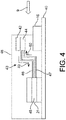
- FIG. 4 One embodiment of different cooling paths is shown in the schematic, side view of FIG. 4 , the front row 11 in ( FIG. 2 ) of GPU heat sinks are designed at a 1U to 1.5U height, but at a lower position than the extended rear GPU heat sink.
- the rear GPU heat sink is designed at a 1.5U to 2.0U upper position, thereby positioning the upper and lower heat sinks in different cooling air paths within housing 48.
- Another embodiment would be to place the heat sinks of the first row and the heat sinks of the second, or last, row in different flow paths by placing the heat sink for the last row in proximity to, or near, the heat sinks for the first row, but in different cooling air flow paths.
- thermo siphon refrigeration system connected between the extended heat sink and the GPUs of the second row.
- an extended heat sink 42 for GPU 21 is placed in the flow path 9 of cooling air at a height above the flow path of cooling air over the lower placed heat sink for GPU 16.
- a refrigeration system in the form of a thermo siphon system, is shown generally at 43 and comprises a chamber or reservoir 44 in combination with extended heat sink 42.
- GPU 21 also contains a chamber or reservoir 45, which is operatively connected to reservoir 44 by a pair of conduits 46, 47.
- the refrigerant in refrigerant system 43 can be any known coolant, such as water or other liquid which boils at a temperature below the boiling point of water, such as a refrigerant discussed in detail below.
- Vapor created by the heating of GPU 21 flows through conduit 47 in direction of the arrow until it reaches reservoir 44, where it condenses.
- the condensed coolant in reservoir 44 flows by gravity in direction of arrow 49 through conduit 46 into reservoir 45, where it is again heated and vaporized.
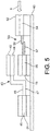
- the front row of 11 of GPUs could also be provided with a refrigerant system, in the form of a thermo siphon system similar in structure and function to that discussed in connection with FIG. 4 , as shown in FIG. 5 .
- a refrigerant system in the form of a thermo siphon system similar in structure and function to that discussed in connection with FIG. 4 , as shown in FIG. 5 .
- the same arrangement of extended heat sink 42 and refrigeration system 43 is provided, as described in connection with FIG. 4 .
- an additional refrigeration system 53 also in the form of a thermo siphon system is provided for the front row of GPUs, as exemplified by GPU 16. Similar to the function of the refrigeration system 43 for the second row of GPUs exemplified by GPU 21, refrigeration system 53 is provided for the first row of GPUs.
- a reservoir 54 in extended heat sink 52 contains a coolant, such as water, or any liquid that boils at a temperature lower than water, such as a refrigerant.
- a coolant such as water, or any liquid that boils at a temperature lower than water, such as a refrigerant.
- Refrigerants such as R134a, R22, R12, R407c, R410a, etc., and combinations thereof, can be utilized, with R134a being preferred.
- Reservoir 54 is connected to reservoir 55 associated with GPU 16.
- Reservoirs 54 and 55 are operatively connected by conduits 56 and 57 respectively, in which a vapor exits reservoir 55 due to heating by GPU 16, and travels via conduit 57 until it condenses in reservoir 54. Condensed liquid refrigerant then flows by gravity through conduit 56 until it reaches reservoir 55, and the cycle begins again.
- conduits 46, 47, 56 and 57 in practice, the heat sinks may be surrounded by fins to improve their cooling efficiency such that the conduits
- the use of the extended heat sinks according to the present embodiment lowers the temperature differential between the first row 11 and the second row 17 of GPUs to about 3°C or less.
- the operating temperatures of the individual GPUs can be reduced and maintained within their operating specification.
Landscapes
- Engineering & Computer Science (AREA)
- Physics & Mathematics (AREA)
- General Engineering & Computer Science (AREA)
- Theoretical Computer Science (AREA)
- Computer Hardware Design (AREA)
- Thermal Sciences (AREA)
- Microelectronics & Electronic Packaging (AREA)
- Human Computer Interaction (AREA)
- General Physics & Mathematics (AREA)
- Cooling Or The Like Of Electrical Apparatus (AREA)
Abstract
A method and structure for improving efficiency of cooling and temperature uniformity among a plurality of heat generating electronic devices arranged in rows within a housing, such as a GPU server, utilizing a single source of cooling air. The electronic devices are arranged in a plurality of rows, but the heat sinks for the last row are elevated above the heat sinks of the first row so as to occupy different positions within the cooling air stream. In some embodiments the heat sinks of the electronic devices are extended forward so as to reside near the heat sinks of the electronic devices in the first row, but in a different flow path of cooling air. In other embodiments, a thermo siphon refrigeration system is provided for the electronic devices in the last row, and may be provided for the electronic devices in the first row as well.
Description
- In server design, heat build-up is of concern - especially in components downstream of the initial airflow provided by a cooling fan, wherein incoming cooling air is pre-heated before reaching downstream components. Recent developments related to the heat output of graphics processing units (GPUs) and central processing units (CPUs) is becoming critical due to the increasingly higher power required for these units. The present disclosure is directed to reducing the temperature disparity between upstream and downstream components without increasing the power load on the cooling fan. The use of an extended heat sink design reduces the temperature disparity of components.
- In server design, increasingly higher power of GPUs is being applied. Currently, the highest power of GPUs is up to 300W, but will soon increase to 400W. Current heat sink design by air cooling alone is too limited to solve temperature disparity among GPUs to bring the temperature of the units into specification.
- As an example of the state of the art in the case of an eight piece GPU modules placed in a server as shown in the schematic layout of
FIG. 1A (Prior Art). A perspective view ofFIG. 1A is shown inFIG. 1B (Prior Art). There is a 2U to 3U height space for GPU heat sink. The placement in of 4 GPUs in the front and 4 GPUs in the rear is as shown inFIGS. 1A and 1B . As can be seen from the placement offan 12 inFIG. 1A , the initial cooling air in the direction ofarrow 9 will pass over the first row of 4 GPUs and cool them to specification. However, the heat picked up by the cooling air results in less cooling in the second row of 4 GPUs. As shown inFIG. 2 (Prior Art), there will be a temperature disparity between the first and second rows of GPUs. The front row of GPUs temperature will be on the order of 6-11°C lower than the temperature of the GPUs in the rear, second row due to this pre-heating of the cooling air. Hence, in this design, there exists these issues: - (a) Poor temperature distribution causes the GPUs located in the worst location to operate at 71.8°C;
- (b) Thermal limitation of supporting GPUs; and
- (c) Higher fan power consumption in attempting to bring GPUs in the worst locations into temperature specification.
- The present disclosure presents a structure and method of reducing the temperature disparity among GPUs without increasing power consumption of the fan.
- In one embodiment of this disclosure, an extended heat sink structure permits more even cooling among the GPUs arranged in an eight piece GPU server.
- In another embodiment, there are provided upper and lower heat sinks separated into different air cooling paths to reduce temperature disparity among the GPUs.
- In a still further embodiment, a thermo-siphon solution is employed where a refrigerant is filled inside a tube and the tube embedded in the extended heat sink.
- The disclosure provides a best thermal design with advantages:
- (a) No preheating of the cooling air and uniform temperature distribution, with temperature differential between the front and back rows of GPUs reduced to 3°C;
- (b) Best heat transfer efficiency of heat sink;
- (c) Reduce worst case temperature location to 65°C; and,
- (d) Lower fan power consumption.
- These and other advantages of the disclosure will be better understood in connection with the detailed description when read in conjunction with the appended drawings.
-
-
FIG. 1A (Prior Art) is a schematic depiction of an eight piece GPU layout in relation to a cooling fan according to the Prior Art. -
FIG. 1B (Prior Art) is a perspective view of the eight piece GPU layout ofFIG. 1A according to the Prior Art. -
FIG. 2 (Prior Art) is a schematic representation of the operating temperatures of the individual GPUs in the eight piece GPU layout ofFIGS. 1A and 1B . -
FIG. 3 is a perspective view of the heat sink structure of an eight piece GPU structure according to a first embodiment. -
FIG. 4 is a schematic side view of the eight piece GPU structure ofFIG. 3 . -
FIG. 5 is a schematic side view of a second embodiment of refrigeration system for thefirst row 11 of GPUs. -
FIG. 6 is a schematic representation of the operating temperatures of the individual GPUs in the eight piece GPU layout ofFIG. 3 according to an embodiment of the disclosure. - The present invention is described with reference to the attached figures, where like reference numerals are used throughout the figures to designate similar or equivalent elements. The figures are not drawn to scale, and they are provided merely to illustrate the instant invention. Several aspects of the invention are described below with reference to example applications for illustration. It should be understood that numerous specific details, relationships, and methods are set forth to provide a full understanding of the invention. One having ordinary skill in the relevant art, however, will readily recognize that the invention can be practiced without one or more of the specific details or with other methods. In other instances, well-known structures or operations are not shown in detail to avoid obscuring the invention. The present invention is not limited by the illustrated ordering of acts or events, as some acts may occur in different orders and/or concurrently with other acts or events. Furthermore, not all illustrated acts or events are required to implement a methodology in accordance with the present invention.
- As shown in
FIGS. 1A and 1B is an eightpiece GPU server 10 according to the Prior Art. Inserver 10,fan 12 provides a flow of cooling air in the direction ofarrow 9, over the heat sinks associated with the individual GPUs contained inserver 10. The heat sinks are conventional heat sinks, such as finned heat sinks, and each is associated with its respective GPU. The individual GPUs, each with their individually associated heat sinks, are arranged into two rows, afront row 11, containingGPUs second row 17, containingGPUs server 10. Accordingly, the heat sinks are all impinged by the same cooling air flow. - The cooling air will impinge upon the
first row 11 containingGPUs first row 11 of GPUs before the cooling air reaches thesecond row 17 ofGPUs first row 11 will mean that the cooling efficiency will not be at peak or optimum value as it impinges on thesecond row 17 of GPUs. - As can be seen in
FIG. 2 , there is a temperature disparity of between 6 °C - 11°C between thefirst row 11 of GPUs and thesecond row 17 of GPUs even though both rows are subjected to the same cooling air; and even though all GPUs are operating at the same power levels. The inefficiency of the cooling air is also caused not only by pre-heating of the cooling air as it passes over thefirst row 11 of GPUs, but also because the pre-heating not only raises the temperature of the cooling air, but also causes eddies in the flow of cooling air which further causes inefficiency of the cooling air impinging uponsecond row 17 of GPUs. The temperature of the GPUs in the second row causes individual GPUs to operate out of the temperature specifications and further degrades the output of theGPU server 10. - In order to overcome the temperature disparity in an eight piece GPU server of the prior art, applicant has created the structure of an eight
piece GPU server 30, as seen inFIG. 3 . The flow of cooling air created byfan 12 in the direction ofarrow 9 is still passed over the individual GPUs in theserver 30. However, applicant has separated the front row of heat sinks and the rear row of heat sinks into different air cooling paths. - One embodiment of different cooling paths is shown in the schematic, side view of
FIG. 4 , thefront row 11 in (FIG. 2 ) of GPU heat sinks are designed at a 1U to 1.5U height, but at a lower position than the extended rear GPU heat sink. The rear GPU heat sink is designed at a 1.5U to 2.0U upper position, thereby positioning the upper and lower heat sinks in different cooling air paths withinhousing 48. Another embodiment would be to place the heat sinks of the first row and the heat sinks of the second, or last, row in different flow paths by placing the heat sink for the last row in proximity to, or near, the heat sinks for the first row, but in different cooling air flow paths. - Furthermore, to further improve the efficiency of the cooling, air flow is increased by the provision of a thermo siphon refrigeration system connected between the extended heat sink and the GPUs of the second row.
- Turning specifically to
FIG. 4 , where an arrangement of GPUs is carried onmotherboard 40, anextended heat sink 42 forGPU 21 is placed in theflow path 9 of cooling air at a height above the flow path of cooling air over the lower placed heat sink forGPU 16. In addition, a refrigeration system, in the form of a thermo siphon system, is shown generally at 43 and comprises a chamber orreservoir 44 in combination withextended heat sink 42.GPU 21 also contains a chamber orreservoir 45, which is operatively connected toreservoir 44 by a pair ofconduits refrigerant system 43 can be any known coolant, such as water or other liquid which boils at a temperature below the boiling point of water, such as a refrigerant discussed in detail below. Vapor created by the heating ofGPU 21 flows throughconduit 47 in direction of the arrow until it reachesreservoir 44, where it condenses. The condensed coolant inreservoir 44 flows by gravity in direction ofarrow 49 throughconduit 46 intoreservoir 45, where it is again heated and vaporized. It should be understood that a similar arrangement of extended heat sinks exists for each of therear row GPUs GPU 21. - In a still further refinement of the improved cooling structure according to the present embodiments, the front row of 11 of GPUs (in
FIG. 2 ) could also be provided with a refrigerant system, in the form of a thermo siphon system similar in structure and function to that discussed in connection withFIG. 4 , as shown inFIG. 5 . As shown inFIG. 5 , the same arrangement ofextended heat sink 42 andrefrigeration system 43 is provided, as described in connection withFIG. 4 . However, anadditional refrigeration system 53, also in the form of a thermo siphon system is provided for the front row of GPUs, as exemplified byGPU 16. Similar to the function of therefrigeration system 43 for the second row of GPUs exemplified byGPU 21,refrigeration system 53 is provided for the first row of GPUs. Areservoir 54 inextended heat sink 52 contains a coolant, such as water, or any liquid that boils at a temperature lower than water, such as a refrigerant. Refrigerants such as R134a, R22, R12, R407c, R410a, etc., and combinations thereof, can be utilized, with R134a being preferred.Reservoir 54 is connected toreservoir 55 associated withGPU 16.Reservoirs conduits reservoir 55 due to heating byGPU 16, and travels viaconduit 57 until it condenses inreservoir 54. Condensed liquid refrigerant then flows by gravity throughconduit 56 until it reachesreservoir 55, and the cycle begins again. Although illustrations are provided forconduits - As shown in the schematic temperature distribution of
FIG. 6 for the individual GPUs shown inFIG. 3 , the use of the extended heat sinks according to the present embodiment, lowers the temperature differential between thefirst row 11 and thesecond row 17 of GPUs to about 3°C or less. Thus, without increasing the power consumption of the cooling fan, the operating temperatures of the individual GPUs can be reduced and maintained within their operating specification. - While we have exemplified heat generating GPUs in an array of eight units in two rows, the principles disclosed herein are applicable to any device having heat generating electronic devices comprising eight or more units arranged in two or more rows, as being the sources of heat in a server. As such, it should be regarded by those skilled in the art that the teaching of the instant disclosure can be applied to the cooling of other heat generating electronic devices, such as the cooling of CPUs.
- The terminology used herein is for the purpose of describing particular embodiments only and is not intended to be limiting of the invention. As used herein, the singular forms "a", "an", and "the" are intended to include the plural forms as well, unless the context clearly indicates otherwise. Furthermore, to the extent that the terms "including", "includes", "having", "has", "with", or variants thereof are used in either the detailed description and/or the claims, such terms are intended to be inclusive in a manner similar to the term "comprising."
- Unless otherwise defined, all terms (including technical and scientific terms) used herein have the same meaning as commonly understood by one of ordinary skill in the art to which this invention belongs. It will be further understood that terms, such as those defined in commonly used dictionaries, should be interpreted as having a meaning that is consistent with their meaning in the context of the relevant art and will not be interpreted in an idealized or overly formal sense unless expressly so defined herein.
Claims (15)
- An extended heat sink (42, 52) in an array of a plurality of heat generating processing units (13, 14, 15, 16, 18, 19, 20, 21) wherein the processing units are placed in at least two rows (11, 17) comprising a front row (11) and at least a rear row (17), and further comprising a source (12) of cooling air causing flow of cooling air in a direction (9) from the front row toward the at least rear row, said extended heat sink characterized in: extending a heat sink from a processing unit in the at least rear row.
- The extended heat sink of claim 1 wherein the front row and the at least rear row are contained in a housing of a server (10).
- The extended heat sink of claim 1 or 2, wherein the extended heat sink further comprises a refrigeration circuit (43, 53); the refrigeration circuit comprising a first reservoir (44, 54) for a refrigerant in the extended heat sink and a second reservoir (45, 55) for the refrigerant in contact with at least one GPU in the at least rear row and at least one conduit (46, 56) for conveying the vapor refrigerant from the second reservoir to the first reservoir, and a second conduit (47, 57) for conveying the liquid refrigerant in the first reservoir to the second reservoir.
- The extended heat sink of claim 3, wherein the conveying of the liquid refrigerant in the second conduit is effected by gravity.
- The extended heat sink of anyone of the claims 1 to 4, wherein the array of processing units numbers eight processing units in total, arranged such that there are four processing units in the front row and four processing units in the at least rear row, and each processing unit in the at least rear row is associated with its own extended heat sink.
- The extended heat sink of claim 3 or claim 4 or claim 5 in dependence on claim 3, wherein the refrigerant is at least one selected from the group consisting of R134a, R22, R12, R407c and R410a.
- The extended heat sink of anyone of the claims 1 to 5, wherein a temperature difference between a processing unit in the front row and a processing unit in the at least rear row is 3 °C or less.
- The extended heat sink of anyone of the claims 1 to 7, wherein the source of cooling air comprises at least one fan.
- The extended heat sink of anyone of the claims 1 to 8, wherein the array of processing units is contained within a housing.
- A method of improving the heat transfer efficiency of a heat sink (42, 52) associated with heat generating electronic devices cooled by a single flow of cooling air, wherein the heat generating electronic devices (13, 14, 15, 16, 18, 19, 20, 21) are arranged in rows comprising a front row (11) and at least a rear row (17) within a housing (48) and each electronic device having its own heat sink, the method characterized in elevating the heat sinks of the at least rear row (17) of electronic devices above the height of the heat sinks of the electronic devices in the front row (11).
- The method of claim 10, further comprising extending the position of the heat sinks of the electronic devices in the at least rear row so as to be positioned near the heat sinks of the electronic devices of the front row.
- The method of claim 10 or 11, wherein the heat generating electronic devices are at least one selected from the group consisting of GPUs and CPUs.
- The method of anyone of the claims 10 to 12, further comprising cooling the heat sinks of the electronic devices in the at least rear row with a thermo siphon (43) utilizing a confined refrigerant which is vaporized by the heat generated by the electronic devices in the at least rear row.
- The method of claim 13, wherein the vaporized refrigerant is condensed into a liquid by removal of heat in the heat sink positioned above the electronic devices of the front row.
- The method of claim 14, further comprising flowing the condensed liquid by the influence of gravity back towards the heat generating electronic device in the at least rear row and repeating the vaporization of refrigerant step.
Applications Claiming Priority (1)
| Application Number | Priority Date | Filing Date | Title |
|---|---|---|---|
| US15/926,068 US10842054B2 (en) | 2018-03-20 | 2018-03-20 | Extended heat sink design in server |
Publications (1)
| Publication Number | Publication Date |
|---|---|
| EP3544398A1 true EP3544398A1 (en) | 2019-09-25 |
Family
ID=63491372
Family Applications (1)
| Application Number | Title | Priority Date | Filing Date |
|---|---|---|---|
| EP18189434.6A Withdrawn EP3544398A1 (en) | 2018-03-20 | 2018-08-17 | Extended heat sink design in server |
Country Status (5)
| Country | Link |
|---|---|
| US (1) | US10842054B2 (en) |
| EP (1) | EP3544398A1 (en) |
| JP (1) | JP2019165191A (en) |
| CN (1) | CN110308775A (en) |
| TW (1) | TW201941677A (en) |
Cited By (1)
| Publication number | Priority date | Publication date | Assignee | Title |
|---|---|---|---|---|
| CN113301765A (en) * | 2020-07-01 | 2021-08-24 | 阿里巴巴集团控股有限公司 | Method for controlling operation state of server heat dissipation component, server system and server |
Families Citing this family (1)
| Publication number | Priority date | Publication date | Assignee | Title |
|---|---|---|---|---|
| US11703921B2 (en) * | 2020-03-09 | 2023-07-18 | Nvidia Corporation | Configurable heatsink |
Citations (5)
| Publication number | Priority date | Publication date | Assignee | Title |
|---|---|---|---|---|
| JPH07283569A (en) * | 1994-04-04 | 1995-10-27 | Advantest Corp | Electronic apparatus |
| US6359781B1 (en) * | 2000-04-21 | 2002-03-19 | Dell Products L.P. | Apparatus for cooling heat generating devices |
| US20140090814A1 (en) * | 2012-09-28 | 2014-04-03 | Hitachi, Ltd. | Cooling system and electronic apparatus using the same |
| US20150043167A1 (en) * | 2013-08-07 | 2015-02-12 | Oracle International Corporation | Heat sinks with interdigitated heat pipes |
| WO2017208461A1 (en) * | 2016-06-03 | 2017-12-07 | 株式会社日立製作所 | Boiling cooling device and electronic device having same mounted thereon |
Family Cites Families (19)
| Publication number | Priority date | Publication date | Assignee | Title |
|---|---|---|---|---|
| JPH01183888A (en) | 1988-01-19 | 1989-07-21 | Hitachi Ltd | Cooling structure of electronic equipment |
| JPH0383993U (en) | 1989-12-18 | 1991-08-26 | ||
| JP2001267773A (en) | 2000-03-16 | 2001-09-28 | Hitachi Ltd | Electronic component cooling device |
| TWI262285B (en) | 2005-06-03 | 2006-09-21 | Foxconn Tech Co Ltd | Loop-type heat exchange apparatus |
| US7420808B2 (en) * | 2006-10-10 | 2008-09-02 | International Business Machines Corporation | Liquid-based cooling system for cooling a multi-component electronics system |
| TWI325754B (en) | 2007-08-28 | 2010-06-01 | Inventec Corp | Heat dissipation module |
| CN101566748B (en) | 2008-04-22 | 2012-03-14 | 鸿富锦精密工业(深圳)有限公司 | Radiating module and backlight module adopting same |
| CN103167780B (en) * | 2011-12-16 | 2016-06-08 | 台达电子企业管理(上海)有限公司 | Power model combined radiator assembly |
| WO2013140761A1 (en) | 2012-03-22 | 2013-09-26 | 日本電気株式会社 | Cooling structure for electronic substrate, and electronic device using same |
| US8872022B2 (en) * | 2012-07-18 | 2014-10-28 | Elwha Llc | Phase-change cooling of subterranean power lines |
| JPWO2014049805A1 (en) * | 2012-09-28 | 2016-08-22 | 株式会社日立製作所 | COOLING SYSTEM AND ELECTRIC DEVICE USING THE SAME |
| CN105474766A (en) | 2013-07-22 | 2016-04-06 | 惠普发展公司,有限责任合伙企业 | Heat sink |
| JP6276959B2 (en) * | 2013-10-11 | 2018-02-07 | 株式会社日立製作所 | Phase change module and electronic device equipped with the same |
| WO2015128951A1 (en) | 2014-02-26 | 2015-09-03 | 株式会社日立製作所 | Semiconductor element cooling device and electronic apparatus |
| US9552025B2 (en) * | 2014-09-23 | 2017-01-24 | Google Inc. | Cooling electronic devices in a data center |
| JP6117288B2 (en) | 2015-07-14 | 2017-04-19 | 古河電気工業株式会社 | Cooling system |
| CN105096237A (en) * | 2015-08-26 | 2015-11-25 | 浪潮电子信息产业股份有限公司 | A Design Method for GPU Expansion |
| CN107024967A (en) * | 2016-02-02 | 2017-08-08 | 研祥智能科技股份有限公司 | Industrial service device and its Multi-path radiating structure |
| US10349561B2 (en) | 2016-04-15 | 2019-07-09 | Google Llc | Cooling electronic devices in a data center |
-
2018
- 2018-03-20 US US15/926,068 patent/US10842054B2/en active Active
- 2018-07-16 TW TW107124547A patent/TW201941677A/en unknown
- 2018-08-01 CN CN201810862688.2A patent/CN110308775A/en active Pending
- 2018-08-17 EP EP18189434.6A patent/EP3544398A1/en not_active Withdrawn
- 2018-08-31 JP JP2018163904A patent/JP2019165191A/en active Pending
Patent Citations (5)
| Publication number | Priority date | Publication date | Assignee | Title |
|---|---|---|---|---|
| JPH07283569A (en) * | 1994-04-04 | 1995-10-27 | Advantest Corp | Electronic apparatus |
| US6359781B1 (en) * | 2000-04-21 | 2002-03-19 | Dell Products L.P. | Apparatus for cooling heat generating devices |
| US20140090814A1 (en) * | 2012-09-28 | 2014-04-03 | Hitachi, Ltd. | Cooling system and electronic apparatus using the same |
| US20150043167A1 (en) * | 2013-08-07 | 2015-02-12 | Oracle International Corporation | Heat sinks with interdigitated heat pipes |
| WO2017208461A1 (en) * | 2016-06-03 | 2017-12-07 | 株式会社日立製作所 | Boiling cooling device and electronic device having same mounted thereon |
Cited By (1)
| Publication number | Priority date | Publication date | Assignee | Title |
|---|---|---|---|---|
| CN113301765A (en) * | 2020-07-01 | 2021-08-24 | 阿里巴巴集团控股有限公司 | Method for controlling operation state of server heat dissipation component, server system and server |
Also Published As
| Publication number | Publication date |
|---|---|
| US10842054B2 (en) | 2020-11-17 |
| TW201941677A (en) | 2019-10-16 |
| JP2019165191A (en) | 2019-09-26 |
| CN110308775A (en) | 2019-10-08 |
| US20190297748A1 (en) | 2019-09-26 |
Similar Documents
| Publication | Publication Date | Title |
|---|---|---|
| JP3950302B2 (en) | Pumping liquid cooler using phase change coolant | |
| US8934245B2 (en) | Heat conveying structure for electronic device | |
| US7499278B2 (en) | Method and apparatus for dissipating heat from an electronic device | |
| US20160073548A1 (en) | Cooling module, cooling module mounting board and electronic device | |
| US10607918B2 (en) | Phase-change cooler and phase-change cooling method | |
| US20150060023A1 (en) | Fin-diffuser heat sink with high conductivity heat spreader | |
| KR20080029756A (en) | Heat dissipation system, computer module and heat dissipation method | |
| US20120291997A1 (en) | Liquid cooling device | |
| CN108015440A (en) | Water-cooling system for laser process equipment | |
| TWI744592B (en) | Combination of server rack and cooling system, cooling system for server rack, and method of maintaining server rack within a predetermined range of temperature | |
| US20150062821A1 (en) | Cooling Structure for Electronic Circuit Board, and Electronic Device Using the Same | |
| US10842054B2 (en) | Extended heat sink design in server | |
| US20180270993A1 (en) | Cooling using a wick with varied thickness | |
| CN109891732A (en) | Thermoelectric heat generation system | |
| US20070272397A1 (en) | Compact liquid cooling unit for high end servers | |
| CN104602486A (en) | Liquid-cooled server | |
| CN109520338A (en) | Parallel condenser and heat radiating device | |
| CN109840002B (en) | A kind of pumpless water cooling sound box cooling control method | |
| US20260082521A1 (en) | Server cooling system | |
| KR102947580B1 (en) | Pulsating heat pipe having a three dimensional structure | |
| CN202663571U (en) | Heat dissipation structure of an electromagnetic heating appliance | |
| GB2520108A (en) | Fin-diffuser heat sink with high conductivity heat spreader | |
| US7929306B2 (en) | Circuit pack cooling solution | |
| CN117979620A (en) | cooling system | |
| CN224037696U (en) | Liquid cooling type heat dissipation system |
Legal Events
| Date | Code | Title | Description |
|---|---|---|---|
| PUAI | Public reference made under article 153(3) epc to a published international application that has entered the european phase |
Free format text: ORIGINAL CODE: 0009012 |
|
| 17P | Request for examination filed |
Effective date: 20190730 |
|
| AK | Designated contracting states |
Kind code of ref document: A1 Designated state(s): AL AT BE BG CH CY CZ DE DK EE ES FI FR GB GR HR HU IE IS IT LI LT LU LV MC MK MT NL NO PL PT RO RS SE SI SK SM TR |
|
| AX | Request for extension of the european patent |
Extension state: BA ME |
|
| 17Q | First examination report despatched |
Effective date: 20200409 |
|
| STAA | Information on the status of an ep patent application or granted ep patent |
Free format text: STATUS: THE APPLICATION HAS BEEN WITHDRAWN |
|
| 18W | Application withdrawn |
Effective date: 20200608 |