EP3544392A1 - Electronic device and method for producing same - Google Patents
Electronic device and method for producing same Download PDFInfo
- Publication number
- EP3544392A1 EP3544392A1 EP17871776.5A EP17871776A EP3544392A1 EP 3544392 A1 EP3544392 A1 EP 3544392A1 EP 17871776 A EP17871776 A EP 17871776A EP 3544392 A1 EP3544392 A1 EP 3544392A1
- Authority
- EP
- European Patent Office
- Prior art keywords
- molded body
- resin molded
- bend portion
- interconnection
- electronic device
- Prior art date
- Legal status (The legal status is an assumption and is not a legal conclusion. Google has not performed a legal analysis and makes no representation as to the accuracy of the status listed.)
- Granted
Links
Images




Classifications
-
- H—ELECTRICITY
- H10—SEMICONDUCTOR DEVICES; ELECTRIC SOLID-STATE DEVICES NOT OTHERWISE PROVIDED FOR
- H10W—GENERIC PACKAGES, INTERCONNECTIONS, CONNECTORS OR OTHER CONSTRUCTIONAL DETAILS OF DEVICES COVERED BY CLASS H10
- H10W74/00—Encapsulations, e.g. protective coatings
- H10W74/01—Manufacture or treatment
-
- H—ELECTRICITY
- H10—SEMICONDUCTOR DEVICES; ELECTRIC SOLID-STATE DEVICES NOT OTHERWISE PROVIDED FOR
- H10W—GENERIC PACKAGES, INTERCONNECTIONS, CONNECTORS OR OTHER CONSTRUCTIONAL DETAILS OF DEVICES COVERED BY CLASS H10
- H10W74/00—Encapsulations, e.g. protective coatings
- H10W74/01—Manufacture or treatment
- H10W74/016—Manufacture or treatment using moulds
-
- H—ELECTRICITY
- H05—ELECTRIC TECHNIQUES NOT OTHERWISE PROVIDED FOR
- H05K—PRINTED CIRCUITS; CASINGS OR CONSTRUCTIONAL DETAILS OF ELECTRIC APPARATUS; MANUFACTURE OF ASSEMBLAGES OF ELECTRICAL COMPONENTS
- H05K1/00—Printed circuits
- H05K1/02—Details
- H05K1/0277—Bendability or stretchability details
- H05K1/028—Bending or folding regions of flexible printed circuits
-
- H—ELECTRICITY
- H05—ELECTRIC TECHNIQUES NOT OTHERWISE PROVIDED FOR
- H05K—PRINTED CIRCUITS; CASINGS OR CONSTRUCTIONAL DETAILS OF ELECTRIC APPARATUS; MANUFACTURE OF ASSEMBLAGES OF ELECTRICAL COMPONENTS
- H05K1/00—Printed circuits
- H05K1/02—Details
- H05K1/14—Structural association of two or more printed circuits
- H05K1/147—Structural association of two or more printed circuits at least one of the printed circuits being bent or folded, e.g. by using a flexible printed circuit
-
- H—ELECTRICITY
- H05—ELECTRIC TECHNIQUES NOT OTHERWISE PROVIDED FOR
- H05K—PRINTED CIRCUITS; CASINGS OR CONSTRUCTIONAL DETAILS OF ELECTRIC APPARATUS; MANUFACTURE OF ASSEMBLAGES OF ELECTRICAL COMPONENTS
- H05K3/00—Apparatus or processes for manufacturing printed circuits
- H05K3/22—Secondary treatment of printed circuits
- H05K3/28—Applying non-metallic protective coatings
- H05K3/284—Applying non-metallic protective coatings for encapsulating mounted components
-
- H—ELECTRICITY
- H10—SEMICONDUCTOR DEVICES; ELECTRIC SOLID-STATE DEVICES NOT OTHERWISE PROVIDED FOR
- H10W—GENERIC PACKAGES, INTERCONNECTIONS, CONNECTORS OR OTHER CONSTRUCTIONAL DETAILS OF DEVICES COVERED BY CLASS H10
- H10W70/00—Package substrates; Interposers; Redistribution layers [RDL]
- H10W70/60—Insulating or insulated package substrates; Interposers; Redistribution layers
- H10W70/611—Insulating or insulated package substrates; Interposers; Redistribution layers for connecting multiple chips together
-
- H—ELECTRICITY
- H10—SEMICONDUCTOR DEVICES; ELECTRIC SOLID-STATE DEVICES NOT OTHERWISE PROVIDED FOR
- H10W—GENERIC PACKAGES, INTERCONNECTIONS, CONNECTORS OR OTHER CONSTRUCTIONAL DETAILS OF DEVICES COVERED BY CLASS H10
- H10W70/00—Package substrates; Interposers; Redistribution layers [RDL]
- H10W70/60—Insulating or insulated package substrates; Interposers; Redistribution layers
- H10W70/67—Insulating or insulated package substrates; Interposers; Redistribution layers characterised by their insulating layers or insulating parts
- H10W70/688—Flexible insulating substrates
-
- H—ELECTRICITY
- H10—SEMICONDUCTOR DEVICES; ELECTRIC SOLID-STATE DEVICES NOT OTHERWISE PROVIDED FOR
- H10W—GENERIC PACKAGES, INTERCONNECTIONS, CONNECTORS OR OTHER CONSTRUCTIONAL DETAILS OF DEVICES COVERED BY CLASS H10
- H10W72/00—Interconnections or connectors in packages
- H10W72/01—Manufacture or treatment
- H10W72/019—Manufacture or treatment of bond pads
-
- H—ELECTRICITY
- H10—SEMICONDUCTOR DEVICES; ELECTRIC SOLID-STATE DEVICES NOT OTHERWISE PROVIDED FOR
- H10W—GENERIC PACKAGES, INTERCONNECTIONS, CONNECTORS OR OTHER CONSTRUCTIONAL DETAILS OF DEVICES COVERED BY CLASS H10
- H10W74/00—Encapsulations, e.g. protective coatings
- H10W74/01—Manufacture or treatment
- H10W74/016—Manufacture or treatment using moulds
- H10W74/017—Auxiliary layers for moulds, e.g. release layers or layers preventing residue
-
- H—ELECTRICITY
- H10—SEMICONDUCTOR DEVICES; ELECTRIC SOLID-STATE DEVICES NOT OTHERWISE PROVIDED FOR
- H10W—GENERIC PACKAGES, INTERCONNECTIONS, CONNECTORS OR OTHER CONSTRUCTIONAL DETAILS OF DEVICES COVERED BY CLASS H10
- H10W74/00—Encapsulations, e.g. protective coatings
- H10W74/01—Manufacture or treatment
- H10W74/019—Manufacture or treatment using temporary auxiliary substrates
-
- H—ELECTRICITY
- H10—SEMICONDUCTOR DEVICES; ELECTRIC SOLID-STATE DEVICES NOT OTHERWISE PROVIDED FOR
- H10W—GENERIC PACKAGES, INTERCONNECTIONS, CONNECTORS OR OTHER CONSTRUCTIONAL DETAILS OF DEVICES COVERED BY CLASS H10
- H10W74/00—Encapsulations, e.g. protective coatings
- H10W74/10—Encapsulations, e.g. protective coatings characterised by their shape or disposition
- H10W74/111—Encapsulations, e.g. protective coatings characterised by their shape or disposition the semiconductor body being completely enclosed
-
- H—ELECTRICITY
- H10—SEMICONDUCTOR DEVICES; ELECTRIC SOLID-STATE DEVICES NOT OTHERWISE PROVIDED FOR
- H10W—GENERIC PACKAGES, INTERCONNECTIONS, CONNECTORS OR OTHER CONSTRUCTIONAL DETAILS OF DEVICES COVERED BY CLASS H10
- H10W74/00—Encapsulations, e.g. protective coatings
- H10W74/10—Encapsulations, e.g. protective coatings characterised by their shape or disposition
- H10W74/111—Encapsulations, e.g. protective coatings characterised by their shape or disposition the semiconductor body being completely enclosed
- H10W74/121—Encapsulations, e.g. protective coatings characterised by their shape or disposition the semiconductor body being completely enclosed by multiple encapsulations, e.g. by a thin protective coating and a thick encapsulation
-
- H—ELECTRICITY
- H05—ELECTRIC TECHNIQUES NOT OTHERWISE PROVIDED FOR
- H05K—PRINTED CIRCUITS; CASINGS OR CONSTRUCTIONAL DETAILS OF ELECTRIC APPARATUS; MANUFACTURE OF ASSEMBLAGES OF ELECTRICAL COMPONENTS
- H05K1/00—Printed circuits
- H05K1/02—Details
- H05K1/14—Structural association of two or more printed circuits
- H05K1/148—Arrangements of two or more hingeably connected rigid printed circuit boards, i.e. connected by flexible means
-
- H—ELECTRICITY
- H05—ELECTRIC TECHNIQUES NOT OTHERWISE PROVIDED FOR
- H05K—PRINTED CIRCUITS; CASINGS OR CONSTRUCTIONAL DETAILS OF ELECTRIC APPARATUS; MANUFACTURE OF ASSEMBLAGES OF ELECTRICAL COMPONENTS
- H05K2203/00—Indexing scheme relating to apparatus or processes for manufacturing printed circuits covered by H05K3/00
- H05K2203/01—Tools for processing; Objects used during processing
- H05K2203/0191—Using tape or non-metallic foil in a process, e.g. during filling of a hole with conductive paste
-
- H—ELECTRICITY
- H05—ELECTRIC TECHNIQUES NOT OTHERWISE PROVIDED FOR
- H05K—PRINTED CIRCUITS; CASINGS OR CONSTRUCTIONAL DETAILS OF ELECTRIC APPARATUS; MANUFACTURE OF ASSEMBLAGES OF ELECTRICAL COMPONENTS
- H05K2203/00—Indexing scheme relating to apparatus or processes for manufacturing printed circuits covered by H05K3/00
- H05K2203/13—Moulding and encapsulation; Deposition techniques; Protective layers
- H05K2203/1305—Moulding and encapsulation
- H05K2203/1316—Moulded encapsulation of mounted components
-
- H—ELECTRICITY
- H05—ELECTRIC TECHNIQUES NOT OTHERWISE PROVIDED FOR
- H05K—PRINTED CIRCUITS; CASINGS OR CONSTRUCTIONAL DETAILS OF ELECTRIC APPARATUS; MANUFACTURE OF ASSEMBLAGES OF ELECTRICAL COMPONENTS
- H05K2203/00—Indexing scheme relating to apparatus or processes for manufacturing printed circuits covered by H05K3/00
- H05K2203/14—Related to the order of processing steps
- H05K2203/1461—Applying or finishing the circuit pattern after another process, e.g. after filling of vias with conductive paste, after making printed resistors
- H05K2203/1469—Circuit made after mounting or encapsulation of the components
-
- H—ELECTRICITY
- H10—SEMICONDUCTOR DEVICES; ELECTRIC SOLID-STATE DEVICES NOT OTHERWISE PROVIDED FOR
- H10W—GENERIC PACKAGES, INTERCONNECTIONS, CONNECTORS OR OTHER CONSTRUCTIONAL DETAILS OF DEVICES COVERED BY CLASS H10
- H10W70/00—Package substrates; Interposers; Redistribution layers [RDL]
- H10W70/099—Connecting interconnections to insulating or insulated package substrates, interposers or redistribution layers
-
- H—ELECTRICITY
- H10—SEMICONDUCTOR DEVICES; ELECTRIC SOLID-STATE DEVICES NOT OTHERWISE PROVIDED FOR
- H10W—GENERIC PACKAGES, INTERCONNECTIONS, CONNECTORS OR OTHER CONSTRUCTIONAL DETAILS OF DEVICES COVERED BY CLASS H10
- H10W70/00—Package substrates; Interposers; Redistribution layers [RDL]
- H10W70/60—Insulating or insulated package substrates; Interposers; Redistribution layers
-
- H—ELECTRICITY
- H10—SEMICONDUCTOR DEVICES; ELECTRIC SOLID-STATE DEVICES NOT OTHERWISE PROVIDED FOR
- H10W—GENERIC PACKAGES, INTERCONNECTIONS, CONNECTORS OR OTHER CONSTRUCTIONAL DETAILS OF DEVICES COVERED BY CLASS H10
- H10W70/00—Package substrates; Interposers; Redistribution layers [RDL]
- H10W70/60—Insulating or insulated package substrates; Interposers; Redistribution layers
- H10W70/611—Insulating or insulated package substrates; Interposers; Redistribution layers for connecting multiple chips together
- H10W70/614—Insulating or insulated package substrates; Interposers; Redistribution layers for connecting multiple chips together the multiple chips being integrally enclosed
-
- H—ELECTRICITY
- H10—SEMICONDUCTOR DEVICES; ELECTRIC SOLID-STATE DEVICES NOT OTHERWISE PROVIDED FOR
- H10W—GENERIC PACKAGES, INTERCONNECTIONS, CONNECTORS OR OTHER CONSTRUCTIONAL DETAILS OF DEVICES COVERED BY CLASS H10
- H10W70/00—Package substrates; Interposers; Redistribution layers [RDL]
- H10W70/60—Insulating or insulated package substrates; Interposers; Redistribution layers
- H10W70/62—Insulating or insulated package substrates; Interposers; Redistribution layers characterised by their interconnections
- H10W70/65—Shapes or dispositions of interconnections
- H10W70/654—Top-view layouts
-
- H—ELECTRICITY
- H10—SEMICONDUCTOR DEVICES; ELECTRIC SOLID-STATE DEVICES NOT OTHERWISE PROVIDED FOR
- H10W—GENERIC PACKAGES, INTERCONNECTIONS, CONNECTORS OR OTHER CONSTRUCTIONAL DETAILS OF DEVICES COVERED BY CLASS H10
- H10W72/00—Interconnections or connectors in packages
- H10W72/01—Manufacture or treatment
- H10W72/0198—Manufacture or treatment batch processes
-
- H—ELECTRICITY
- H10—SEMICONDUCTOR DEVICES; ELECTRIC SOLID-STATE DEVICES NOT OTHERWISE PROVIDED FOR
- H10W—GENERIC PACKAGES, INTERCONNECTIONS, CONNECTORS OR OTHER CONSTRUCTIONAL DETAILS OF DEVICES COVERED BY CLASS H10
- H10W72/00—Interconnections or connectors in packages
- H10W72/90—Bond pads, in general
- H10W72/941—Dispositions of bond pads
- H10W72/9413—Dispositions of bond pads on encapsulations
-
- H—ELECTRICITY
- H10—SEMICONDUCTOR DEVICES; ELECTRIC SOLID-STATE DEVICES NOT OTHERWISE PROVIDED FOR
- H10W—GENERIC PACKAGES, INTERCONNECTIONS, CONNECTORS OR OTHER CONSTRUCTIONAL DETAILS OF DEVICES COVERED BY CLASS H10
- H10W74/00—Encapsulations, e.g. protective coatings
- H10W74/10—Encapsulations, e.g. protective coatings characterised by their shape or disposition
-
- H—ELECTRICITY
- H10—SEMICONDUCTOR DEVICES; ELECTRIC SOLID-STATE DEVICES NOT OTHERWISE PROVIDED FOR
- H10W—GENERIC PACKAGES, INTERCONNECTIONS, CONNECTORS OR OTHER CONSTRUCTIONAL DETAILS OF DEVICES COVERED BY CLASS H10
- H10W90/00—Package configurations
-
- H—ELECTRICITY
- H10—SEMICONDUCTOR DEVICES; ELECTRIC SOLID-STATE DEVICES NOT OTHERWISE PROVIDED FOR
- H10W—GENERIC PACKAGES, INTERCONNECTIONS, CONNECTORS OR OTHER CONSTRUCTIONAL DETAILS OF DEVICES COVERED BY CLASS H10
- H10W90/00—Package configurations
- H10W90/10—Configurations of laterally-adjacent chips
-
- H—ELECTRICITY
- H10—SEMICONDUCTOR DEVICES; ELECTRIC SOLID-STATE DEVICES NOT OTHERWISE PROVIDED FOR
- H10W—GENERIC PACKAGES, INTERCONNECTIONS, CONNECTORS OR OTHER CONSTRUCTIONAL DETAILS OF DEVICES COVERED BY CLASS H10
- H10W90/00—Package configurations
- H10W90/401—Package configurations characterised by multiple insulating or insulated package substrates, interposers or RDLs
-
- H—ELECTRICITY
- H10—SEMICONDUCTOR DEVICES; ELECTRIC SOLID-STATE DEVICES NOT OTHERWISE PROVIDED FOR
- H10W—GENERIC PACKAGES, INTERCONNECTIONS, CONNECTORS OR OTHER CONSTRUCTIONAL DETAILS OF DEVICES COVERED BY CLASS H10
- H10W90/00—Package configurations
- H10W90/701—Package configurations characterised by the relative positions of pads or connectors relative to package parts
- H10W90/721—Package configurations characterised by the relative positions of pads or connectors relative to package parts of bump connectors
- H10W90/724—Package configurations characterised by the relative positions of pads or connectors relative to package parts of bump connectors between a chip and a stacked insulating package substrate, interposer or RDL
Definitions
- the present technique relates to a partially bendable electronic device and a method for manufacturing the same.
- the device has only a limited area for fixing a rigid substrate on which electronic components are mounted. Accordingly, a technique is known in which a bendable flexible substrate is used to connect a plurality of rigid substrates that are not in the same plane.
- Fig. 11 shows an example electronic device that combines rigid substrates and a flexible substrate.
- the electronic device shown in Fig. 11 includes rigid substrates 70, 75 and a flexible substrate 80.
- Rigid substrate 70 has an electronic component 71 mounted thereon, the electronic component 71 being connected to interconnections 72a, 72b formed on rigid substrate 70.
- Rigid substrate 75 has electronic components 76a, 76b mounted thereon, the electronic components 76a, 76b being connected to interconnections 77a to 77c formed on rigid substrate 75.
- a conductive layer 81 which is formed on flexible substrate 80, is connected to interconnection 72b of substrate 70 via a conductive adhesive layer 90a and is also connected to interconnection 77a of substrate 75 via a conductive adhesive layer 90b.
- substrates 70, 75 are electrically connected to each other via bendable flexible substrate 80.
- each of rigid substrates 70, 75 requires a terminal area for connection to flexible substrate 80, resulting in enlarged substrate area. Further, the increase in man-hour for assembly increases the manufacturing cost.
- Japanese Patent Laying-Open No. 6-177490 discloses a printed wiring board produced by integrating a flexible wiring board and rigid wiring boards together by sandwiching the flexible wiring board between the rigid wiring boards from above and below with adhesive layers being interposed.
- the flexible wiring board and the rigid wiring boards can be connected via interlayer circuit interconnections, such as through holes. This eliminates the need for a terminal area for connection to the flexible substrate, thus preventing enlarged substrate area.
- the printed wiring substrate is disadvantageously thick. Further, the printed wiring substrate is thicker by electronic components mounted on the printed wiring substrate via, for example, solder.
- the technique requires, for example, laminating press and a large apparatus for multi-layering the rigid wiring boards and the flexible substrate. This disadvantageously increases the manufacturing cost.
- An object of the present invention is to provide an electronic device including a bendable bend portion and having a reduced size and thickness, and also provide a method for manufacturing such an electronic device with reduced manufacturing cost.
- an electronic device comprises: an electronic component; a resin molded body in which the electronic component is embedded and fixed; and a bendable bend portion continuous with the resin molded body.
- the bend portion is molded integrally with the resin molded body with resin.
- the resin molded body may support the bend portion, with a part of the bend portion being embedded in the resin molded body.
- a surface of the resin molded body includes an exposed surface at which the electronic component is exposed.
- a surface of the bend portion includes a continuous surface continuous with the exposed surface.
- the electronic device further comprises an interconnection formed on the exposed surface and on the continuous surface, the interconnection being connected to the electronic component.
- the interconnection extends continuously from the electronic component to the continuous surface.
- the interconnection may include a first interconnection formed on the exposed surface and connected to the electronic component, and a second interconnection formed on the continuous surface beforehand and connected to the first interconnection.
- the material of the bend portion is higher in breaking elongation percentage than the material of the resin molded body.
- the bend portion may be made of a resin having a breaking elongation percentage of 300% or more.
- the resin molded body may be made of a resin having a breaking elongation percentage of 150% or less.
- the resin molded body may contain a filler.
- a method for manufacturing an electronic device comprises: sticking an electronic component to a sheet; placing the sheet in a molding die and filling the molding die with resin, thereby integrally molding a resin molded body and a bendable bend portion, the resin molded body having the electronic component embedded therein, the bend portion being thinner than the resin molded body; and forming an interconnection on a sheet bonded surface of the resin molded body and on a continuous surface of the bend portion, the sheet bonded surface having been in contact with the sheet and exposed by peeling the sheet from the resin molded body, the continuous surface being continuous with the sheet bonded surface.
- a method for manufacturing an electronic device comprises: sticking an electronic component to a sheet; placing the sheet in two types of molding dies in order and performing two-color molding to integrally mold a resin molded body and a bendable bend portion, the resin molded body having the electronic component embedded therein, the bend portion being continuous with the resin molded body; and forming an interconnection on a sheet bonded surface of the resin molded body and on a continuous surface of the bend portion, the sheet bonded surface having been in contact with the sheet and exposed by peeling the sheet from the resin molded body, the continuous surface being continuous with the sheet bonded surface.
- a method for manufacturing an electronic device comprises: sticking an electronic component and a bendable bend portion to a sheet; placing the sheet in a molding die and filling the molding die with resin, thereby molding a resin molded body in which the electronic component and a part of the bend portion are embedded; and forming a first interconnection on a sheet bonded surface of the resin molded body, the sheet bonded surface having been in contact with the sheet and exposed by peeling the sheet from the resin molded body.
- a surface of the bend portion includes a continuous surface continuous with the sheet bonded surface.
- the forming the first interconnection includes forming the first interconnection on the continuous surface.
- a second interconnection may be formed beforehand on a surface of the bend portion.
- the sticking may include sticking the bend portion to the sheet so that the second interconnection faces the sheet; and the forming the first interconnection may include forming the first interconnection so that the first interconnection is connected to the second interconnection.
- the present disclosure can provide an electronic device including a bendable bend portion and having a reduced size and thickness.
- FIG. 1 is a plan view showing a schematic configuration of electronic device 100 in embodiment 1.
- Fig. 2 is a cross-sectional view taken along line X-X and seen in the arrow direction in Fig. 1 .
- Electronic device 100 is built in various types of electronic equipment, such as portable electronic equipment (e.g. wearable portable equipment), and a small-sized sensor, so that electronic device 100 performs a principal or auxiliary function of the electronic equipment.
- portable electronic equipment e.g. wearable portable equipment
- a small-sized sensor so that electronic device 100 performs a principal or auxiliary function of the electronic equipment.
- wearable portable equipment include a measuring instrument attached to clothes to measure a human body surface temperature; and a measuring instrument wound around an arm to measure a pulse, a blood pressure, or the like.
- electronic device 100 includes a main portion 10 having an electronic circuit formed thereon, a bendable bend portion 20, and an interconnection 30 (30a to 30h).
- Main portion 10 includes a resin molded body 11 and an electronic component 12 (12a to 12e).
- Resin molded body 11 is generally in the form of a plate and is made of resin, such as polycarbonate (PC) or acrylonitrile-butadiene-styrene (ABS).
- the shape of resin molded body 11 is not particularly limited, and may be designed as appropriate in accordance with the shape of electronic device 100.
- the material of resin molded body 11 may be other types of resin (e.g. polypropylene (PP), or elastomer).
- Resin molded body 11 has electronic component 12 (12a to 12e) embedded therein, thereby fixing electronic component 12. Resin molded body 11 has electronic component 12 embedded therein, so that electronic component 12 is exposed at an upper surface 11a.
- Electronic component 12 (12a to 12e) is, for example, a chip capacitor, a chip resistance, or an integrated circuit (IC).
- the number and type of electronic components 12 are not particularly limited.
- the surfaces of electronic components 12a to 12e exposed at resin molded body 11 respectively have electrodes 13a to 13e formed thereon.
- Bend portion 20 is continuous with resin molded body 11 and is bendable. Specifically, bend portion 20 is made of the same material as resin molded body 11 and is molded integrally with resin molded body 11. Bend portion 20 has a thickness t1 (e.g. 0.2 mm) thinner than a thickness t2 (e.g. 3 mm) of resin molded body 11 so that bend portion 20 is more bendable than resin molded body 11.
- t1 e.g. 0.2 mm
- t2 e.g. 3 mm
- the surface of bend portion 20 includes a continuous surface 20a continuous with upper surface 11a of resin molded body 11.
- two surfaces being “continuous” refers to a state in which the step between the two surfaces is so small that an interconnection formed on the surfaces does not break.
- continuous surface 20a of bend portion 20 is flush with upper surface 11a of resin molded body 11.
- Interconnection 30 (30a to 30h) is formed on at least upper surface 11a of upper surface 11a of resin molded body 11 and continuous surface 20a of bend portion 20. Interconnection 30 (30a to 30h) is connected to any of electrodes 13a to 13e of electronic components 12a to 12e.
- interconnections 30a to 30c are formed both on upper surface 11a of resin molded body 11 and on continuous surface 20a of bend portion 20, and continuously extend from electrode 13e of electronic component 12e, electrode 13d of electronic component 12d, and electrode 13b of electronic component 12b, respectively, to continuous surface 20a.
- Interconnections 30d to 30h are formed on upper surface 11a of resin molded body 11.
- Interconnection 30d is connected to electrode 13a of electronic component 12a and electrode 13b of electronic component 12b.
- Interconnection 30e is connected to electrode 13a of electronic component 12a and electrode 13c of electronic component 12c.
- Interconnection 30f is connected to electrode 13c of electronic component 12c and electrode 13d of electronic component 12d.
- Interconnection 30g is connected to electrode 13a of electronic component 12a and electrode 13d of electronic component 12d.
- Interconnection 30h is connected to electrode 13d of electronic component 12d and electrode 13e of electronic component 12e.
- Interconnection 30 can be easily formed by, for example, ink-jet printing with silver (Ag) ink.
- the ink-jet printing is a printing method in which ink is jetted from nozzles so that particulate ink deposits on a jetting target plane.
- interconnection 30 can be easily formed by ink-jet printing with silver (Ag) ink.
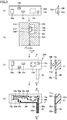
- FIG. 3 is a diagram explaining a method for manufacturing electronic device 100. Diagrams for explaining the first to fourth steps for manufacturing electronic device 100 are shown in (a) to (d) of Fig. 3 respectively.
- a plan view is shown on the left, and a side view is shown on the right.
- a cross-sectional view is shown.
- a plan view is shown on the left, and a cross-sectional view taken along line X-X and seen in the arrow direction in the plan view is shown on the right.
- Temporary fixation sheet 200 examples include polyethylene terephthalate (PET), polyethylene naphthalate (PEN), and polyphenylene sulfide (PPS).
- PET polyethylene terephthalate
- PEN polyethylene naphthalate
- PPS polyphenylene sulfide
- Temporary fixation sheet 200 is preferably made of a material transparent to ultraviolet rays and having flexibility for the reasons described later.
- the temporary fixation can be performed with, for example, an ultraviolet curable adhesive (not shown) applied to one side of temporary fixation sheet 200.
- an ultraviolet curable adhesive is applied, with a thickness of 2 to 3 ⁇ m, to PET temporary fixation sheet 200 having a thickness of 50 ⁇ m.
- This application may be performed by, for example, ink-jet printing.
- electronic components 12a to 12e are placed at prescribed positions.
- electronic components 12a to 12e are irradiated with ultraviolet rays having an intensity of, for example, 3000 mJ/cm 2 , from the side of temporary fixation sheet 200 on which electronic components 12a to 12e are not temporarily fixed.
- the adhesive cures and temporarily fixes electronic components 12a to 12e to temporary fixation sheet 200.
- temporary fixation sheet 200 having electronic components 12a to 12e temporarily fixed thereto is placed in a molding die formed by combining a first die 210 and a second die 220.
- first die 210 that faces second die 220 has a recess 211 having the same shape as temporary fixation sheet 200. In this recess 211, temporary fixation sheet 200 is fitted. Thus, the surface of temporary fixation sheet 200 having electronic components 12a to 12e stuck thereto faces second die 220.
- the depth of recess 211 is the same as the thickness of temporary fixation sheet 200. Accordingly, the surface of temporary fixation sheet 200 having electronic component 12 temporarily fixed thereto is flush with the surface of a part (where recess 211 is not formed) of first die 210 that faces second die 220.
- the surface of second die 220 that faces first die 210 has a shape such that a space 221 having a depth t2 is defined at the part that faces recess 211 of first die 210, and such that a space 222 having a depth t1 is defined at the part that does not face recess 211 of first die 210.
- Space 221 communicates with space 222.
- Injection molding of resin is performed by injecting resin material in spaces 221, 222 in the molding die formed by combining first die 210 and second die 220.
- the conditions for the injection molding may be selected as appropriate in accordance with the resin. If polycarbonate (PC) is used, the injection molding is performed under an injection resin temperature of 270°C and an injection pressure of 100 MPa, for example.
- PC polycarbonate
- resin material various types can be used.
- the conditions for the injection molding are not particularly limited.
- Structure 230 includes resin molded body 11 which has the same shape (thickness t2) as space 221 of the molding die, and a bend portion 20 which has the same shape (thickness t1) as space 222 of the molding die.
- temporary fixation sheet 200 is peeled from structure 230.
- surfaces of electronic components 12a to 12e are exposed at the sheet bonded surface (corresponding to upper surface 11a) of resin molded body 11 that has been in contact with temporary fixation sheet 200.
- temporary fixation sheet 200 is a PET film, it largely deforms due to thermal change during the second step. Thus, temporary fixation sheet 200 can be easily peeled from structure 230.
- interconnection 30 (30a to 30h) in a predetermined pattern is formed on upper surface 11a of resin molded body 11 and on continuous surface 20a of bend portion 20.
- interconnection 30 can be performed by a method of spraying conductive material (e.g. silver ink) by ink-jet printing, by a method using aerosol, or by a method using a dispenser, for example.
- conductive material e.g. silver ink
- interconnection 30 can be easily formed with a high degree of freedom of circuit design, and each of electronic components 12a to 12e can be electrically connected simply and easily with no solder. Further, in industrial terms, since electronic components 12a to 12e can be connected after their positions are determined, electronic components 12a to 12e can be electrically connected more correctly and easily than in the case in which the positions of electronic components are adjusted on a printed substrate, for example.
- electronic device 100 is completed, where electronic device 100 is provided with: main portion 10 including electronic component 12 and resin molded body 11; bend portion 20; and interconnection 30.
- electronic device 100 includes electronic component 12, resin molded body 11 in which electronic component 12 is embedded and fixed, and bendable bend portion 20 continuous with resin molded body 11.
- Resin molded body 11 in which electronic component 12 is embedded and fixed, serves as a substrate on which electronic components are mounted.
- electronic device 100 can be reduced in size and thickness compared to a conventional one in which electronic components are mounted on the upper surface of a rigid substrate via, for example, solder.
- bend portion 20 is continuous with resin molded body 11, electronic device 100 can be reduced in size and thickness compared to a case in which a flexible wiring board is sandwiched between rigid wiring boards from above and below (see Japanese Patent Laying-Open No. 6-177490 ).
- Bend portion 20 is molded integrally with resin molded body 11. Thus, there is no connecting point that receives mechanical load between bend portion 20 and resin molded body 11. This increases reliability in connection between resin molded body 11 and bend portion 20. Further, there is no need to use a separate flexible substrate, which is comparatively expensive. Thus the cost of components is reduced.
- the surface of resin molded body 11 includes upper surface (exposed surface) 11a at which electronic component 12 is exposed.
- the surface of bend portion 20 includes continuous surface 20a continuous with upper surface 11a.
- Electronic device 100 includes interconnection 30 formed on upper surface 11a and on continuous surface 20a, the interconnection 30 being connected to electronic component 12. This eliminates the need for a terminal area for electrically connecting the bend portion and resin molded body 11. Thus, further downsizing is achieved.
- Electronic device 100 is manufactured by the steps in the following (1) to (3):
- electrical connection between main portion 10 and bend portion 20 is achieved by forming interconnection 30 on upper surface 11a of resin molded body 11 and on continuous surface 20a of bend portion 20.
- An electronic device in embodiment 2 of the present invention which is a variation of electronic device 100 in embodiment 1, is provided with a plurality of main portions each including an electronic component and a resin molded body.
- Fig. 4 is a plan view showing a schematic configuration of an electronic device 100A in embodiment 2.
- Fig. 5 is a cross-sectional view taken along line X-X and seen in the arrow direction in Fig. 4 .
- electronic device 100A is different from electronic device 100 in embodiment 1 in that electronic device 100A includes a main portion 40 and interconnections 30i to 30k.
- Main portion 40 is connected to an end of bend portion 20, opposite to the end connected to main portion 10.
- Main portion 40 includes a resin molded body 41 and an electronic component 42 (42a to 42c).
- Resin molded body 41 is generally in the form of a plate. Resin molded body 41 is made of the same resin as resin molded body 11 and bend portion 20. Also, resin molded body 41 is molded integrally with resin molded body 11 and bend portion 20.
- Resin molded body 41 has electronic component 42 (42a to 42c) embedded therein, thereby fixing electronic component 42.
- Resin molded body 41 has electronic component 42 embedded therein, so that electronic component 42 is exposed at an upper surface 41a.
- Upper surface 41a of resin molded body 41 is continuous with continuous surface 20a of bend portion 20 and is flush with upper surface 11a of resin molded body 11 and continuous surface 20a.
- Electronic component 42 (42a to 42c) is, for example, a chip capacitor, a chip resistance, or an integrated circuit (IC).
- the number and type of electronic components 42 are not particularly limited.
- the surfaces of electronic components 42a to 42c exposed at resin molded body 41 respectively have electrodes 43a to 43c formed thereon.
- Interconnections 30i to 30k are formed on upper surface 41a of resin molded body 41 and are connected to electrodes 43a to 43c of electronic components 42a to 42c.
- interconnections 30a to 30c formed on continuous surface 20a of bend portion 20 are extended to upper surface 41a of resin molded body 41.
- Interconnection 30a is connected to electrode 43b of electronic component 42b.
- Interconnections 30b, 30c are connected to electrode 43c of electronic component 42c.
- Electronic device 100A is manufactured in a method similar to that of embodiment 1. Specifically, in the first step described in embodiment 1, a temporary fixation sheet having electronic component 42 temporarily fixed thereto is prepared, separately from temporary fixation sheet 200 having electronic component 12 temporarily fixed thereto. In the second step, temporary fixation sheet 200 having electronic component 12 temporarily fixed thereto and the temporary fixation sheet having electronic component 42 temporarily fixed thereto are placed in a molding die. Then, the molding die is injected with resin material to perform injection molding of resin. Thus, resin molded bodies 11, 41 and bend portion 20 are integrally molded. After that, in the fourth step, interconnection 30 (30a to 30k) may be formed on upper surface 11a of resin molded body 11, on upper surface 41a of resin molded body 41, and on continuous surface 20a of bend portion 20 continuous with upper surfaces 11a, 41a.
- bendable bend portion 20 is disposed between a plurality of main portions 10, 40. Accordingly, even if main portion 10 and main portion 40 are placed not in the same plane, electronic device 100A can be built in electronic equipment, with the electronic circuit on main portion 10 being electrically connected to the electronic circuit on main portion 40 via bend portion 20.
- An electronic device in embodiment 3 of the present invention is a variation of electronic device 100 in embodiment 1 or electronic device 100A in embodiment 2.
- the material of bend portion 20 is different from the material of resin molded body 11 of main portion 10 and resin molded body 41 of main portion 40.
- resin molded body 11 of main portion 10 and resin molded body 41 of main portion 40 are preferably made of a resin material having a breaking elongation percentage of 150% or less, such as polycarbonate (PC) or acrylonitrile-butadiene-styrene (ABS).
- the breaking elongation percentage refers to an elongation percentage of specimen at the time of breakage when a tensile test is performed in accordance with JIS K 7162, relative to the specimen before the test.
- main portions 10, 40 are less likely to deform and thus can be easily fixed in position.
- bend portion 20 is preferably made of a resin material having a breaking elongation percentage of 300% or more, such as polyurethane (PU), which has a breaking elongation percentage of 580%, or polyamide (PA), which has a breaking elongation percentage of 300%.
- PU polyurethane
- PA polyamide
- electronic device 100, 100A can be built in electronic equipment with bend portion 20 being elongated as necessary, depending on the other configuration of the electronic equipment in which electronic device 100, 100A is built, and depending on the positions at which main portions 10, 40 are placed.
- electronic device 100, 100A can be easily built in electronic equipment, even if there are variations in internal configuration among electronic equipments or even if some design change has been made in the internal configuration.
- bend portion 20 is placed near human joints.
- bend portion 20 made of a resin material having a breaking elongation percentage of 300% or more can expand and contract in accordance with the motion of the person wearing the clothes.
- Main portion 10 including a temperature sensor as electronic component 12 is placed at a comparatively stable position remote from human joints.
- Resin molded body 11 of main portion 10 preferably has elasticity to some degree in order to reduce stimulus to a human body when coming in contact with the human body surface.
- the resin material constituting resin molded body 11 is selected as appropriate from resin materials having a breaking elongation percentage of 150% or less, depending on the position at which main portion 10 is placed.
- bend portion 20 is made of the same resin material as resin molded body 11 of main portion 10 and resin molded body 41 of main portion 40, a filler (e.g. a glass filler or a carbon filler) is preferably added to the resin material constituting resin molded body 11 and resin molded body 41.
- a filler e.g. a glass filler or a carbon filler
- This can increase the intensity of main portions 10, 40.
- adding a glass filler is particularly preferable.
- a conventionally known method such as the two-color molding, may be used.
- the two-color molding is a method for integral molding by combining different resins or different materials. Specifically, resin molded body 11 is molded in a first molding die, and then bend portion 20 is molded in a second molding die, so that resin molded body 11 and bend portion 20 are integrally molded. Alternatively, bend portion 20 may be molded in a first molding die, and then resin molded body 11 may be molded in a second molding die, so that resin molded body 11 and bend portion 20 are integrally molded.
- bend portion 20 is made of a material having a high breaking elongation percentage, bend portion 20 may have the same thickness as resin molded body 11.
- bend portion 20 is molded by injection molding of resin material.
- an electronic device in embodiment 4 uses a flexible substrate as a bend portion.
- FIG. 6 is a plan view showing a schematic configuration of electronic device 100B in embodiment 4.
- Fig. 7 is a cross-sectional view taken along line X-X and seen in the arrow direction in Fig. 6 .
- electronic device 100B is different from electronic device 100 in embodiment 1 in that electronic device 100B includes a main portion 50 instead of main portion 10, and includes a bend portion 60 instead of bend portion 20.
- Bend portion 60 is a flexible substrate in the form of a film made of, for example, polyimide (PI) or polyethylene terephthalate (PET).
- the shape of bend portion 60 may be, but not limited to, a rectangular shape for example.
- the thickness of bend portion 60 may be, but not limited to, 50 ⁇ m for example.
- Main portion 50 is different from main portion 10 in embodiment 1 in that main portion 50 includes a resin molded body 51, instead of resin molded body 11.
- Resin molded body 51 is generally in the form of a plate and is made of resin, such as polycarbonate (PC) or acrylonitrile-butadiene-styrene (ABS).
- the shape of resin molded body 51 is not particularly limited, and may be designed as appropriate in accordance with the shape of electronic device 100B.
- the material of resin molded body 51 may be other types of resin (e.g. polypropylene (PP), or elastomer).
- Resin molded body 51 has electronic component 12 (12a to 12e) embedded therein, thereby fixing electronic component 12, similarly to resin molded body 11. Resin molded body 51 has electronic component 12 embedded therein, so that electronic component 12 is exposed at an upper surface 51a.
- resin molded body 51 supports bend portion 60, with a part of bend portion 60 being embedded in resin molded body 51.
- bend portion 60 is continuous with resin molded body 51.
- resin molded body 51 supports bend portion 60, with the end (including one short side) of rectangular bend portion 60 being embedded in resin molded body 51.
- Resin molded body 51 supports bend portion 60, with upper surface 51a being continuous with a part (continuous surface 60a) of the surface of bend portion 60.
- resin molded body 51 supports bend portion 60, with upper surface 51a being flush with continuous surface 60a of bend portion 60.
- interconnection 30 (30a to 30h) is formed on at least one of upper surface 51a of resin molded body 51 and continuous surface 60a of bend portion 60, and is connected to any of electronic components 12a to 12e.
- FIG. 8 is a diagram explaining a method for manufacturing electronic device 100B. Diagrams for explaining the first to fourth steps for manufacturing electronic device 100B are shown in (a) to (d) of Fig. 8 respectively.
- a plan view is shown on the left, and a side view is shown on the right.
- a cross-sectional view is shown.
- a plan view is shown on the left, and a cross-sectional view taken along line X-X and seen in the arrow direction in the plan view is shown on the right.
- temporary fixation sheet 200 having electronic components 12a to 12e and bend portion 60 temporarily fixed thereto is placed in a molding die formed by combining first die 210 and second die 220.
- Injection molding of resin is performed by injecting resin material in space 221 in the molding die formed by combining first die 210 and second die 220.
- the conditions for the injection molding are the same as those of the second step in embodiment 1.
- Structure 240 includes resin molded body 51 in which electronic components 12a to 12e are embedded, the resin molded body 51 having the same shape as space 221 in the molding die. Structure 240 also includes bend portion 60 partially embedded in resin molded body 51.
- temporary fixation sheet 200 is peeled from structure 240.
- surfaces of electronic components 12a to 12e are exposed at upper surface 51a of resin molded body 51.
- Continuous surface 60a of bend portion 60 that has been stuck to temporary fixation sheet 200 is flush with and continuous with upper surface 51a of resin molded body 51.
- interconnection 30 (30a to 30h) in a predetermined pattern is formed on upper surface 51a of resin molded body 51 and on continuous surface 60a of bend portion 60.
- the method for forming interconnection 30 is the same as the fourth step in embodiment 1.
- electronic device 100B is completed, where electronic device 100B is provided with: main portion 50 including electronic component 12 and resin molded body 51; bend portion 60 supported by resin molded body 51; and interconnection 30.
- resin molded body 51 supports bend portion 60, with a part of bend portion 60 being embedded in resin molded body 51. This provides more reliable connection between bend portion 60 and resin molded body 51 than bonding with an adhesive or the like.
- Electronic device 100B is manufactured by the steps in the following (1) to (3):
- electronic device 100B including bend portion 60 can be easily manufactured.
- the manufacturing cost of electronic device 100B can be reduced.
- Interconnection 30 is formed also on continuous surface 60a of bend portion 60 continuous with upper surface 51a of resin molded body 51.
- electrical connection between main portion 50 and bend portion 60 is achieved by forming interconnection 30 on upper surface 51a of resin molded body 51 and on continuous surface 60a of bend portion 60.
- An electronic device in embodiment 5 of the present invention which is a variation of electronic device 100B in embodiment 4, has an interconnection formed beforehand on bend portion 60 which is a flexible substrate.
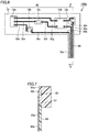
- Fig. 9 is a plan view showing a schematic configuration of an electronic device 100C in embodiment 5.
- Fig. 10 is a cross-sectional view taken along line XI-XI and seen in the arrow direction in Fig. 9 .
- electronic device 100C includes main portion 50, bend portion 60, and interconnection (first interconnection) 30 (30d to 30h, 30m, 30n, 30p).
- An interconnection (second interconnection) 61 (61a to 61c) is formed beforehand on continuous surface 60a of bend portion 60 continuous with upper surface 51a of resin molded body 51.
- Interconnection 61 is made of copper having a thickness of, for example, about 12 ⁇ m.
- interconnection 61 may be made of, for example, aluminum instead of copper.
- Interconnection 30m is connected to interconnection 61c formed on bend portion 60 and is connected to electronic component 12b.
- Interconnection 30n is connected to interconnection 61b formed on bend portion 60 and is connected to electronic component 12d.
- Interconnection 30p is connected to interconnection 61a formed on bend portion 60 and is connected to electronic component 12e.
- bend portion 60 a flexible substrate on which interconnections have already been formed can be used as bend portion 60.
- Electronic device 100C is manufactured in a manufacturing method similar to electronic device 100B in embodiment 4 described above (see Fig. 8 ). However, in the first step shown in Fig. 8 , bend portion 60 is stuck to temporary fixation sheet 200 so that interconnection 61 faces (in contact with) temporary fixation sheet 200. Accordingly, after the injection molding of resin, interconnection 61 is flush with upper surface (sheet bonded surface) 51a of resin molded body 51 that has been in contact with temporary fixation sheet 200. As a result, in forming interconnection 30, a part of interconnection 30 can be easily connected to interconnection 61. Thus, interconnection 61 on bend portion 60 (which is a flexible substrate) can easily be connected to interconnection 30 formed on resin molded body 51. This eliminates the need for conventional complicated processes for connecting a flexible substrate to a rigid substrate, and also eliminates the need for an adhesive or other like members. Thus, the manufacturing cost of electronic device 100C can be reduced.
- 10, 40, 50 main portion; 11, 41, 51: resin molded body; 11a, 41a, 51a: upper surface; 12 (12a to 12e), 42 (42a to 42c), 71, 76a, 76b: electronic component; 13a to 13e, 43a to 43c: electrode; 20, 60: bend portion; 20a, 60a: continuous surface; 30 (30a to 30p), 61 (61a to 61c), 72a, 72b, 77a, 77c: interconnection; 70, 75, 80: substrate; 81: conductive layer; 90a, 90b: conductive adhesive layer; 100, 100A, 100B, 100C: electronic device; 200: temporary fixation sheet; 210: first die; 211: recess; 220: second die; 221, 222: space; 230, 240: structure
Landscapes
- Engineering & Computer Science (AREA)
- Microelectronics & Electronic Packaging (AREA)
- Manufacturing & Machinery (AREA)
- Structure Of Printed Boards (AREA)
- Structures Or Materials For Encapsulating Or Coating Semiconductor Devices Or Solid State Devices (AREA)
- Production Of Multi-Layered Print Wiring Board (AREA)
- Structures For Mounting Electric Components On Printed Circuit Boards (AREA)
- Encapsulation Of And Coatings For Semiconductor Or Solid State Devices (AREA)
Abstract
Description
- The present technique relates to a partially bendable electronic device and a method for manufacturing the same.
- In recent years, due to increasing demand for microminiaturization of a portable device and the like, the device has only a limited area for fixing a rigid substrate on which electronic components are mounted. Accordingly, a technique is known in which a bendable flexible substrate is used to connect a plurality of rigid substrates that are not in the same plane.
-
Fig. 11 shows an example electronic device that combines rigid substrates and a flexible substrate. The electronic device shown inFig. 11 includesrigid substrates flexible substrate 80. -
Rigid substrate 70 has anelectronic component 71 mounted thereon, theelectronic component 71 being connected tointerconnections rigid substrate 70.Rigid substrate 75 haselectronic components electronic components interconnections 77a to 77c formed onrigid substrate 75. Aconductive layer 81, which is formed onflexible substrate 80, is connected tointerconnection 72b ofsubstrate 70 via a conductiveadhesive layer 90a and is also connected tointerconnection 77a ofsubstrate 75 via a conductiveadhesive layer 90b. Thus,substrates flexible substrate 80. - In the electronic device shown in
Fig. 11 , however, each ofrigid substrates flexible substrate 80, resulting in enlarged substrate area. Further, the increase in man-hour for assembly increases the manufacturing cost. - Japanese Patent Laying-Open No.
6-177490 6-177490 - PTL 1: Japanese Patent Laying-Open No.
6-177490 - In the technique described in Japanese Patent Laying-Open No.
6-177490 - Further, the technique requires, for example, laminating press and a large apparatus for multi-layering the rigid wiring boards and the flexible substrate. This disadvantageously increases the manufacturing cost.
- The present invention has been made by focusing on the problems of the conventional technique described above. An object of the present invention is to provide an electronic device including a bendable bend portion and having a reduced size and thickness, and also provide a method for manufacturing such an electronic device with reduced manufacturing cost.
- According to one aspect, an electronic device comprises: an electronic component; a resin molded body in which the electronic component is embedded and fixed; and a bendable bend portion continuous with the resin molded body.
- Preferably, the bend portion is molded integrally with the resin molded body with resin. Alternatively, the resin molded body may support the bend portion, with a part of the bend portion being embedded in the resin molded body.
- Preferably, a surface of the resin molded body includes an exposed surface at which the electronic component is exposed. A surface of the bend portion includes a continuous surface continuous with the exposed surface. The electronic device further comprises an interconnection formed on the exposed surface and on the continuous surface, the interconnection being connected to the electronic component.
- For example, the interconnection extends continuously from the electronic component to the continuous surface. Alternatively, the interconnection may include a first interconnection formed on the exposed surface and connected to the electronic component, and a second interconnection formed on the continuous surface beforehand and connected to the first interconnection.
- The material of the bend portion is higher in breaking elongation percentage than the material of the resin molded body. For example, the bend portion may be made of a resin having a breaking elongation percentage of 300% or more. The resin molded body may be made of a resin having a breaking elongation percentage of 150% or less. The resin molded body may contain a filler.
- According to another aspect, a method for manufacturing an electronic device comprises: sticking an electronic component to a sheet; placing the sheet in a molding die and filling the molding die with resin, thereby integrally molding a resin molded body and a bendable bend portion, the resin molded body having the electronic component embedded therein, the bend portion being thinner than the resin molded body; and forming an interconnection on a sheet bonded surface of the resin molded body and on a continuous surface of the bend portion, the sheet bonded surface having been in contact with the sheet and exposed by peeling the sheet from the resin molded body, the continuous surface being continuous with the sheet bonded surface.
- According to still another aspect, a method for manufacturing an electronic device comprises: sticking an electronic component to a sheet; placing the sheet in two types of molding dies in order and performing two-color molding to integrally mold a resin molded body and a bendable bend portion, the resin molded body having the electronic component embedded therein, the bend portion being continuous with the resin molded body; and forming an interconnection on a sheet bonded surface of the resin molded body and on a continuous surface of the bend portion, the sheet bonded surface having been in contact with the sheet and exposed by peeling the sheet from the resin molded body, the continuous surface being continuous with the sheet bonded surface.
- According to still another aspect, a method for manufacturing an electronic device comprises: sticking an electronic component and a bendable bend portion to a sheet; placing the sheet in a molding die and filling the molding die with resin, thereby molding a resin molded body in which the electronic component and a part of the bend portion are embedded; and forming a first interconnection on a sheet bonded surface of the resin molded body, the sheet bonded surface having been in contact with the sheet and exposed by peeling the sheet from the resin molded body.
- Preferably, a surface of the bend portion includes a continuous surface continuous with the sheet bonded surface. The forming the first interconnection includes forming the first interconnection on the continuous surface.
- Alternatively, a second interconnection may be formed beforehand on a surface of the bend portion. The sticking may include sticking the bend portion to the sheet so that the second interconnection faces the sheet; and the forming the first interconnection may include forming the first interconnection so that the first interconnection is connected to the second interconnection.
- The present disclosure can provide an electronic device including a bendable bend portion and having a reduced size and thickness.
-
-
Fig. 1 is a plan view showing a schematic configuration of an electronic device inembodiment 1. -
Fig. 2 is a cross-sectional view taken along line X-X and seen in the arrow direction inFig. 1 . -
Fig. 3 is a diagram explaining a method for manufacturing an electronic device inembodiment 1. -
Fig. 4 is a plan view showing a schematic configuration of an electronic device in embodiment 2. -
Fig. 5 is a cross-sectional view taken along line X-X and seen in the arrow direction inFig. 4 . -
Fig. 6 is a plan view showing a schematic configuration of an electronic device in embodiment 4. -
Fig. 7 is a cross-sectional view taken along line X-X and seen in the arrow direction inFig. 6 . -
Fig. 8 is a diagram explaining a method for manufacturing an electronic device in embodiment 4. -
Fig. 9 is a plan view showing a schematic configuration of an electronic device in embodiment 5. -
Fig. 10 is a cross-sectional view taken along line XI-XI and seen in the arrow direction inFig. 9 . -
Fig. 11 is a diagram showing an example electronic device that combines rigid substrates and a flexible substrate. - Embodiments of the present invention are described in detail with reference to the drawings. In the drawings, identical or corresponding parts are identically denoted, and the explanation thereof is not repeated.
- With reference to
Fig. 1 and Fig. 2 , a schematic configuration of anelectronic device 100 inembodiment 1 is described.Fig. 1 is a plan view showing a schematic configuration ofelectronic device 100 inembodiment 1.Fig. 2 is a cross-sectional view taken along line X-X and seen in the arrow direction inFig. 1 . -
Electronic device 100 is built in various types of electronic equipment, such as portable electronic equipment (e.g. wearable portable equipment), and a small-sized sensor, so thatelectronic device 100 performs a principal or auxiliary function of the electronic equipment. Examples of wearable portable equipment include a measuring instrument attached to clothes to measure a human body surface temperature; and a measuring instrument wound around an arm to measure a pulse, a blood pressure, or the like. - As shown in
Fig. 1 and Fig. 2 ,electronic device 100 includes amain portion 10 having an electronic circuit formed thereon, abendable bend portion 20, and an interconnection 30 (30a to 30h).Main portion 10 includes a resin moldedbody 11 and an electronic component 12 (12a to 12e). - Resin molded
body 11 is generally in the form of a plate and is made of resin, such as polycarbonate (PC) or acrylonitrile-butadiene-styrene (ABS). The shape of resin moldedbody 11 is not particularly limited, and may be designed as appropriate in accordance with the shape ofelectronic device 100. The material of resin moldedbody 11 may be other types of resin (e.g. polypropylene (PP), or elastomer). - Resin molded
body 11 has electronic component 12 (12a to 12e) embedded therein, thereby fixing electronic component 12. Resin moldedbody 11 has electronic component 12 embedded therein, so that electronic component 12 is exposed at anupper surface 11a. - Electronic component 12 (12a to 12e) is, for example, a chip capacitor, a chip resistance, or an integrated circuit (IC). The number and type of electronic components 12 are not particularly limited.
- The surfaces of
electronic components 12a to 12e exposed at resin moldedbody 11 respectively haveelectrodes 13a to 13e formed thereon. -
Bend portion 20 is continuous with resin moldedbody 11 and is bendable. Specifically,bend portion 20 is made of the same material as resin moldedbody 11 and is molded integrally with resin moldedbody 11.Bend portion 20 has a thickness t1 (e.g. 0.2 mm) thinner than a thickness t2 (e.g. 3 mm) of resin moldedbody 11 so thatbend portion 20 is more bendable than resin moldedbody 11. - The surface of
bend portion 20 includes acontinuous surface 20a continuous withupper surface 11a of resin moldedbody 11. Here, two surfaces being "continuous" refers to a state in which the step between the two surfaces is so small that an interconnection formed on the surfaces does not break. Specifically,continuous surface 20a ofbend portion 20 is flush withupper surface 11a of resin moldedbody 11. - Interconnection 30 (30a to 30h) is formed on at least
upper surface 11a ofupper surface 11a of resin moldedbody 11 andcontinuous surface 20a ofbend portion 20. Interconnection 30 (30a to 30h) is connected to any ofelectrodes 13a to 13e ofelectronic components 12a to 12e. - Specifically,
interconnections 30a to 30c are formed both onupper surface 11a of resin moldedbody 11 and oncontinuous surface 20a ofbend portion 20, and continuously extend fromelectrode 13e ofelectronic component 12e,electrode 13d ofelectronic component 12d, andelectrode 13b ofelectronic component 12b, respectively, tocontinuous surface 20a. -
Interconnections 30d to 30h are formed onupper surface 11a of resin moldedbody 11.Interconnection 30d is connected toelectrode 13a ofelectronic component 12a andelectrode 13b ofelectronic component 12b.Interconnection 30e is connected toelectrode 13a ofelectronic component 12a andelectrode 13c ofelectronic component 12c.Interconnection 30f is connected toelectrode 13c ofelectronic component 12c andelectrode 13d ofelectronic component 12d.Interconnection 30g is connected toelectrode 13a ofelectronic component 12a andelectrode 13d ofelectronic component 12d.Interconnection 30h is connected toelectrode 13d ofelectronic component 12d andelectrode 13e ofelectronic component 12e. - Interconnection 30 can be easily formed by, for example, ink-jet printing with silver (Ag) ink. The ink-jet printing is a printing method in which ink is jetted from nozzles so that particulate ink deposits on a jetting target plane.
- Since
upper surface 11a of resin moldedbody 11 is continuous withcontinuous surface 20a ofbend portion 20 as described above, interconnection 30 can be easily formed by ink-jet printing with silver (Ag) ink. - Next, with reference to
Fig. 3 , an example method for manufacturingelectronic device 100 inembodiment 1 is described.Fig. 3 is a diagram explaining a method for manufacturingelectronic device 100. Diagrams for explaining the first to fourth steps for manufacturingelectronic device 100 are shown in (a) to (d) ofFig. 3 respectively. In (a) ofFig. 3 , a plan view is shown on the left, and a side view is shown on the right. In (b) ofFig. 3 , a cross-sectional view is shown. In each of (c) and (d) ofFig. 3 , a plan view is shown on the left, and a cross-sectional view taken along line X-X and seen in the arrow direction in the plan view is shown on the right. - As shown in (a) of
Fig. 3 , first,electronic components 12a to 12e are stuck to a rectangulartemporary fixation sheet 200 with an adhesive (not shown), so as to be temporarily fixed thereto. At this time,electronic components 12a to 12e are stuck in such a manner that the side on whichelectrodes 13a to 13e are formed is in contact withtemporary fixation sheet 200. - Examples of the material of
temporary fixation sheet 200 include polyethylene terephthalate (PET), polyethylene naphthalate (PEN), and polyphenylene sulfide (PPS).Temporary fixation sheet 200 is preferably made of a material transparent to ultraviolet rays and having flexibility for the reasons described later. - The temporary fixation can be performed with, for example, an ultraviolet curable adhesive (not shown) applied to one side of
temporary fixation sheet 200. For example, an ultraviolet curable adhesive is applied, with a thickness of 2 to 3 µm, to PETtemporary fixation sheet 200 having a thickness of 50 µm. This application may be performed by, for example, ink-jet printing. After that,electronic components 12a to 12e are placed at prescribed positions. Then,electronic components 12a to 12e are irradiated with ultraviolet rays having an intensity of, for example, 3000 mJ/cm2, from the side oftemporary fixation sheet 200 on whichelectronic components 12a to 12e are not temporarily fixed. Thus, the adhesive cures and temporarily fixeselectronic components 12a to 12e totemporary fixation sheet 200. - Next, as shown in (b) of
Fig. 3 ,temporary fixation sheet 200 havingelectronic components 12a to 12e temporarily fixed thereto is placed in a molding die formed by combining afirst die 210 and asecond die 220. - The surface of
first die 210 that facessecond die 220 has arecess 211 having the same shape astemporary fixation sheet 200. In thisrecess 211,temporary fixation sheet 200 is fitted. Thus, the surface oftemporary fixation sheet 200 havingelectronic components 12a to 12e stuck thereto facessecond die 220. - The depth of
recess 211 is the same as the thickness oftemporary fixation sheet 200. Accordingly, the surface oftemporary fixation sheet 200 having electronic component 12 temporarily fixed thereto is flush with the surface of a part (whererecess 211 is not formed) offirst die 210 that facessecond die 220. - The surface of
second die 220 that faces first die 210 has a shape such that aspace 221 having a depth t2 is defined at the part that facesrecess 211 offirst die 210, and such that aspace 222 having a depth t1 is defined at the part that does not facerecess 211 offirst die 210.Space 221 communicates withspace 222. - Injection molding of resin is performed by injecting resin material in
spaces first die 210 andsecond die 220. - The conditions for the injection molding may be selected as appropriate in accordance with the resin. If polycarbonate (PC) is used, the injection molding is performed under an injection resin temperature of 270°C and an injection pressure of 100 MPa, for example.
- As the resin for the injection molding, various types of resin material can be used. A material having rubber elasticity, such as elastomer, allows more flexible deformation of
bend portion 20. The conditions for the injection molding are not particularly limited. - As shown in (c) of
Fig. 3 , astructure 230 obtained by injection molding at the second step is taken out of the molding die.Structure 230 includes resin moldedbody 11 which has the same shape (thickness t2) asspace 221 of the molding die, and abend portion 20 which has the same shape (thickness t1) asspace 222 of the molding die. - Then,
temporary fixation sheet 200 is peeled fromstructure 230. Thus, surfaces ofelectronic components 12a to 12e are exposed at the sheet bonded surface (corresponding toupper surface 11a) of resin moldedbody 11 that has been in contact withtemporary fixation sheet 200. - If
temporary fixation sheet 200 is a PET film, it largely deforms due to thermal change during the second step. Thus,temporary fixation sheet 200 can be easily peeled fromstructure 230. - In the second step, when
temporary fixation sheet 200 is fitted intorecess 211 offirst die 210, the surface oftemporary fixation sheet 200 having electronic component 12 temporarily fixed thereto is flush with the surface offirst die 210 that facessecond die 220. Therefore, the surface of the part ofbend portion 20 that has been in contact withfirst die 210 formscontinuous surface 20a that is continuous with and flush withupper surface 11a of resin moldedbody 11. - As shown in (d) of
Fig. 3 , after the third step, interconnection 30 (30a to 30h) in a predetermined pattern is formed onupper surface 11a of resin moldedbody 11 and oncontinuous surface 20a ofbend portion 20. - The formation of interconnection 30 can be performed by a method of spraying conductive material (e.g. silver ink) by ink-jet printing, by a method using aerosol, or by a method using a dispenser, for example.
- Using a method selected as appropriate, interconnection 30 can be easily formed with a high degree of freedom of circuit design, and each of
electronic components 12a to 12e can be electrically connected simply and easily with no solder. Further, in industrial terms, sinceelectronic components 12a to 12e can be connected after their positions are determined,electronic components 12a to 12e can be electrically connected more correctly and easily than in the case in which the positions of electronic components are adjusted on a printed substrate, for example. - Thus,
electronic device 100 is completed, whereelectronic device 100 is provided with:main portion 10 including electronic component 12 and resin moldedbody 11;bend portion 20; and interconnection 30. - As described above,
electronic device 100 includes electronic component 12, resin moldedbody 11 in which electronic component 12 is embedded and fixed, andbendable bend portion 20 continuous with resin moldedbody 11. - Resin molded
body 11, in which electronic component 12 is embedded and fixed, serves as a substrate on which electronic components are mounted. Thus,electronic device 100 can be reduced in size and thickness compared to a conventional one in which electronic components are mounted on the upper surface of a rigid substrate via, for example, solder. - Further, since
bend portion 20 is continuous with resin moldedbody 11,electronic device 100 can be reduced in size and thickness compared to a case in which a flexible wiring board is sandwiched between rigid wiring boards from above and below (see Japanese Patent Laying-Open No.6-177490 -
Bend portion 20 is molded integrally with resin moldedbody 11. Thus, there is no connecting point that receives mechanical load betweenbend portion 20 and resin moldedbody 11. This increases reliability in connection between resin moldedbody 11 andbend portion 20. Further, there is no need to use a separate flexible substrate, which is comparatively expensive. Thus the cost of components is reduced. - The surface of resin molded
body 11 includes upper surface (exposed surface) 11a at which electronic component 12 is exposed. The surface ofbend portion 20 includescontinuous surface 20a continuous withupper surface 11a.Electronic device 100 includes interconnection 30 formed onupper surface 11a and oncontinuous surface 20a, the interconnection 30 being connected to electronic component 12. This eliminates the need for a terminal area for electrically connecting the bend portion and resin moldedbody 11. Thus, further downsizing is achieved. -
Electronic device 100 is manufactured by the steps in the following (1) to (3): - (1) sticking electronic component 12 to
temporary fixation sheet 200; - (2) placing
temporary fixation sheet 200 in a molding die (first die 210 and second die 220) and filling the molding die with resin, thereby integrally molding resin moldedbody 11 andbendable bend portion 20, the resin moldedbody 11 having electronic component 12 embedded therein, thebend portion 20 being thinner than resin moldedbody 11; and - (3) forming interconnection 30 on upper surface (sheet bonded surface) 11a of resin molded
body 11 and oncontinuous surface 20a ofbend portion 20, theupper surface 11a having been in contact withtemporary fixation sheet 200 and exposed by peelingtemporary fixation sheet 200 from resin moldedbody 11, thecontinuous surface 20a being continuous withupper surface 11a. - By the above-described manufacturing method, electrical connection between
main portion 10 andbend portion 20 is achieved by forming interconnection 30 onupper surface 11a of resin moldedbody 11 and oncontinuous surface 20a ofbend portion 20. This eliminates the need for conventional complicated processes for connecting a flexible substrate to a rigid substrate, and also eliminates the need for an adhesive or other like members. Thus, the manufacturing cost ofelectronic device 100 can be reduced. - An electronic device in embodiment 2 of the present invention, which is a variation of
electronic device 100 inembodiment 1, is provided with a plurality of main portions each including an electronic component and a resin molded body. -
Fig. 4 is a plan view showing a schematic configuration of anelectronic device 100A in embodiment 2.Fig. 5 is a cross-sectional view taken along line X-X and seen in the arrow direction inFig. 4 . - As shown in
Fig. 4 and Fig. 5 ,electronic device 100A is different fromelectronic device 100 inembodiment 1 in thatelectronic device 100A includes amain portion 40 andinterconnections 30i to 30k. -
Main portion 40 is connected to an end ofbend portion 20, opposite to the end connected tomain portion 10.Main portion 40 includes a resin moldedbody 41 and an electronic component 42 (42a to 42c). - Resin molded
body 41 is generally in the form of a plate. Resin moldedbody 41 is made of the same resin as resin moldedbody 11 andbend portion 20. Also, resin moldedbody 41 is molded integrally with resin moldedbody 11 andbend portion 20. - Resin molded
body 41 has electronic component 42 (42a to 42c) embedded therein, thereby fixing electronic component 42. Resin moldedbody 41 has electronic component 42 embedded therein, so that electronic component 42 is exposed at anupper surface 41a. -
Upper surface 41a of resin moldedbody 41 is continuous withcontinuous surface 20a ofbend portion 20 and is flush withupper surface 11a of resin moldedbody 11 andcontinuous surface 20a. - Electronic component 42 (42a to 42c) is, for example, a chip capacitor, a chip resistance, or an integrated circuit (IC). The number and type of electronic components 42 are not particularly limited.
- The surfaces of
electronic components 42a to 42c exposed at resin moldedbody 41 respectively haveelectrodes 43a to 43c formed thereon. -
Interconnections 30i to 30k are formed onupper surface 41a of resin moldedbody 41 and are connected toelectrodes 43a to 43c ofelectronic components 42a to 42c. - In embodiment 2,
interconnections 30a to 30c formed oncontinuous surface 20a ofbend portion 20 are extended toupper surface 41a of resin moldedbody 41.Interconnection 30a is connected toelectrode 43b ofelectronic component 42b.Interconnections electrode 43c ofelectronic component 42c. -
Electronic device 100A is manufactured in a method similar to that ofembodiment 1. Specifically, in the first step described inembodiment 1, a temporary fixation sheet having electronic component 42 temporarily fixed thereto is prepared, separately fromtemporary fixation sheet 200 having electronic component 12 temporarily fixed thereto. In the second step,temporary fixation sheet 200 having electronic component 12 temporarily fixed thereto and the temporary fixation sheet having electronic component 42 temporarily fixed thereto are placed in a molding die. Then, the molding die is injected with resin material to perform injection molding of resin. Thus, resin moldedbodies bend portion 20 are integrally molded. After that, in the fourth step, interconnection 30 (30a to 30k) may be formed onupper surface 11a of resin moldedbody 11, onupper surface 41a of resin moldedbody 41, and oncontinuous surface 20a ofbend portion 20 continuous withupper surfaces - According to the above-described configuration,
bendable bend portion 20 is disposed between a plurality ofmain portions main portion 10 andmain portion 40 are placed not in the same plane,electronic device 100A can be built in electronic equipment, with the electronic circuit onmain portion 10 being electrically connected to the electronic circuit onmain portion 40 viabend portion 20. - An electronic device in embodiment 3 of the present invention is a variation of
electronic device 100 inembodiment 1 orelectronic device 100A in embodiment 2. In the electronic device in embodiment 3, the material ofbend portion 20 is different from the material of resin moldedbody 11 ofmain portion 10 and resin moldedbody 41 ofmain portion 40. - For example, resin molded
body 11 ofmain portion 10 and resin moldedbody 41 ofmain portion 40 are preferably made of a resin material having a breaking elongation percentage of 150% or less, such as polycarbonate (PC) or acrylonitrile-butadiene-styrene (ABS). The breaking elongation percentage refers to an elongation percentage of specimen at the time of breakage when a tensile test is performed in accordance with JIS K 7162, relative to the specimen before the test. - Therefore,
main portions - On the other hand,
bend portion 20 is preferably made of a resin material having a breaking elongation percentage of 300% or more, such as polyurethane (PU), which has a breaking elongation percentage of 580%, or polyamide (PA), which has a breaking elongation percentage of 300%. - Therefore,
electronic device bend portion 20 being elongated as necessary, depending on the other configuration of the electronic equipment in whichelectronic device main portions electronic device - If
electronic device 100A is built in a measuring instrument attached to clothes (e.g. underwear) for measuring a human body surface temperature,bend portion 20 is placed near human joints. In this case,bend portion 20 made of a resin material having a breaking elongation percentage of 300% or more can expand and contract in accordance with the motion of the person wearing the clothes. -
Main portion 10 including a temperature sensor as electronic component 12 is placed at a comparatively stable position remote from human joints. Resin moldedbody 11 ofmain portion 10 preferably has elasticity to some degree in order to reduce stimulus to a human body when coming in contact with the human body surface. The resin material constituting resin moldedbody 11 is selected as appropriate from resin materials having a breaking elongation percentage of 150% or less, depending on the position at whichmain portion 10 is placed. - If
bend portion 20 is made of the same resin material as resin moldedbody 11 ofmain portion 10 and resin moldedbody 41 ofmain portion 40, a filler (e.g. a glass filler or a carbon filler) is preferably added to the resin material constituting resin moldedbody 11 and resin moldedbody 41. This can increase the intensity ofmain portions - In order to make the material of
bend portion 20 different from the material of resin moldedbody 11 ofmain portion 10 and resin moldedbody 41 ofmain portion 40, a conventionally known method, such as the two-color molding, may be used. - The two-color molding is a method for integral molding by combining different resins or different materials. Specifically, resin molded
body 11 is molded in a first molding die, and then bendportion 20 is molded in a second molding die, so that resin moldedbody 11 andbend portion 20 are integrally molded. Alternatively,bend portion 20 may be molded in a first molding die, and then resin moldedbody 11 may be molded in a second molding die, so that resin moldedbody 11 andbend portion 20 are integrally molded. - If
bend portion 20 is made of a material having a high breaking elongation percentage,bend portion 20 may have the same thickness as resin moldedbody 11. - In the above described
embodiments 1 to 3,bend portion 20 is molded by injection molding of resin material. However, an electronic device in embodiment 4 uses a flexible substrate as a bend portion. - With reference to
Fig. 6 and Fig. 7 , a configuration of anelectronic device 100B in embodiment 4 is described.Fig. 6 is a plan view showing a schematic configuration ofelectronic device 100B in embodiment 4.Fig. 7 is a cross-sectional view taken along line X-X and seen in the arrow direction inFig. 6 . - As shown in
Fig. 6 and Fig. 7 ,electronic device 100B is different fromelectronic device 100 inembodiment 1 in thatelectronic device 100B includes amain portion 50 instead ofmain portion 10, and includes abend portion 60 instead ofbend portion 20. -
Bend portion 60 is a flexible substrate in the form of a film made of, for example, polyimide (PI) or polyethylene terephthalate (PET). The shape ofbend portion 60 may be, but not limited to, a rectangular shape for example. The thickness ofbend portion 60 may be, but not limited to, 50 µm for example. -
Main portion 50 is different frommain portion 10 inembodiment 1 in thatmain portion 50 includes a resin moldedbody 51, instead of resin moldedbody 11. - Resin molded
body 51 is generally in the form of a plate and is made of resin, such as polycarbonate (PC) or acrylonitrile-butadiene-styrene (ABS). The shape of resin moldedbody 51 is not particularly limited, and may be designed as appropriate in accordance with the shape ofelectronic device 100B. The material of resin moldedbody 51 may be other types of resin (e.g. polypropylene (PP), or elastomer). - Resin molded
body 51 has electronic component 12 (12a to 12e) embedded therein, thereby fixing electronic component 12, similarly to resin moldedbody 11. Resin moldedbody 51 has electronic component 12 embedded therein, so that electronic component 12 is exposed at anupper surface 51a. - Further, resin molded
body 51 supports bendportion 60, with a part ofbend portion 60 being embedded in resin moldedbody 51. Thus,bend portion 60 is continuous with resin moldedbody 51. In the example shown inFig. 6 and Fig. 7 , resin moldedbody 51 supports bendportion 60, with the end (including one short side) ofrectangular bend portion 60 being embedded in resin moldedbody 51. Resin moldedbody 51 supports bendportion 60, withupper surface 51a being continuous with a part (continuous surface 60a) of the surface ofbend portion 60. Specifically, resin moldedbody 51 supports bendportion 60, withupper surface 51a being flush withcontinuous surface 60a ofbend portion 60. - Similarly to
embodiment 1, interconnection 30 (30a to 30h) is formed on at least one ofupper surface 51a of resin moldedbody 51 andcontinuous surface 60a ofbend portion 60, and is connected to any ofelectronic components 12a to 12e. - Next, with reference to
Fig. 8 , an example method for manufacturingelectronic device 100B in embodiment 4 is described.Fig. 8 is a diagram explaining a method for manufacturingelectronic device 100B. Diagrams for explaining the first to fourth steps for manufacturingelectronic device 100B are shown in (a) to (d) ofFig. 8 respectively. In (a) ofFig. 8 , a plan view is shown on the left, and a side view is shown on the right. In (b) ofFig. 8 , a cross-sectional view is shown. In each of (c) and (d) ofFig. 8 , a plan view is shown on the left, and a cross-sectional view taken along line X-X and seen in the arrow direction in the plan view is shown on the right. - As shown in (a) of
Fig. 8 , first,electronic components 12a to 12e andbend portion 60 are stuck to rectangulartemporary fixation sheet 200 with an adhesive, so as to be temporarily fixed thereto. At this time,electronic components 12a to 12e are stuck in such a manner that the side on whichelectrodes 13a to 13e are formed is in contact withtemporary fixation sheet 200. Only a part ofbend portion 60 is stuck totemporary fixation sheet 200. The method for temporarily fixingelectronic components 12a to 12e andbend portion 60 totemporary fixation sheet 200 is the same as the first step inembodiment 1, and thus the detailed explanation is not repeated. - Next, as shown in (b) of
Fig. 8 ,temporary fixation sheet 200 havingelectronic components 12a to 12e andbend portion 60 temporarily fixed thereto is placed in a molding die formed by combiningfirst die 210 andsecond die 220. - Similarly to
embodiment 1,temporary fixation sheet 200 is fitted intorecess 211 defined infirst die 210. At this time,bend portion 60 lies substantially across thewhole space 222, and a part ofbend portion 60 protrudes intospace 221. - Injection molding of resin is performed by injecting resin material in
space 221 in the molding die formed by combiningfirst die 210 andsecond die 220. The conditions for the injection molding are the same as those of the second step inembodiment 1. - As shown in (c) of
Fig. 8 , astructure 240 obtained by injection molding at the second step is taken out of the molding die.Structure 240 includes resin moldedbody 51 in whichelectronic components 12a to 12e are embedded, the resin moldedbody 51 having the same shape asspace 221 in the molding die.Structure 240 also includesbend portion 60 partially embedded in resin moldedbody 51. - Then,
temporary fixation sheet 200 is peeled fromstructure 240. Thus, surfaces ofelectronic components 12a to 12e are exposed atupper surface 51a of resin moldedbody 51.Continuous surface 60a ofbend portion 60 that has been stuck totemporary fixation sheet 200 is flush with and continuous withupper surface 51a of resin moldedbody 51. - As shown in (d) of
Fig. 8 , after the third step, interconnection 30 (30a to 30h) in a predetermined pattern is formed onupper surface 51a of resin moldedbody 51 and oncontinuous surface 60a ofbend portion 60. The method for forming interconnection 30 is the same as the fourth step inembodiment 1. - Thus,
electronic device 100B is completed, whereelectronic device 100B is provided with:main portion 50 including electronic component 12 and resin moldedbody 51;bend portion 60 supported by resin moldedbody 51; and interconnection 30. - (Advantages)
- In
electronic device 100B in embodiment 4, resin moldedbody 51 supports bendportion 60, with a part ofbend portion 60 being embedded in resin moldedbody 51. This provides more reliable connection betweenbend portion 60 and resin moldedbody 51 than bonding with an adhesive or the like. -
Electronic device 100B is manufactured by the steps in the following (1) to (3): - (1) sticking electronic component 12 and
bendable bend portion 60 totemporary fixation sheet 200; - (2) placing
temporary fixation sheet 200 in a molding die (formed by combiningfirst die 210 and second die 220) and filling the molding die with resin, thereby molding resin moldedbody 51 in which electronic component 12 and a part ofbend portion 60 are embedded; and - (3) forming interconnection (first interconnection) 30 on upper surface (sheet bonded surface) 51a of resin molded
body 51, theupper surface 51a having been in contact withtemporary fixation sheet 200 and exposed by peelingtemporary fixation sheet 200 from resin moldedbody 51. - In this way,
electronic device 100B includingbend portion 60 can be easily manufactured. Thus, the manufacturing cost ofelectronic device 100B can be reduced. - Interconnection 30 is formed also on
continuous surface 60a ofbend portion 60 continuous withupper surface 51a of resin moldedbody 51. Thus, electrical connection betweenmain portion 50 andbend portion 60 is achieved by forming interconnection 30 onupper surface 51a of resin moldedbody 51 and oncontinuous surface 60a ofbend portion 60. This eliminates the need for conventional complicated processes for connecting a flexible substrate to a rigid substrate, and also eliminates the need for an adhesive or other like members. Thus, the manufacturing cost ofelectronic device 100B can be reduced. - An electronic device in embodiment 5 of the present invention, which is a variation of
electronic device 100B in embodiment 4, has an interconnection formed beforehand onbend portion 60 which is a flexible substrate. -
Fig. 9 is a plan view showing a schematic configuration of anelectronic device 100C in embodiment 5.Fig. 10 is a cross-sectional view taken along line XI-XI and seen in the arrow direction inFig. 9 . - As shown in
Fig. 9 and Fig. 10 ,electronic device 100C includesmain portion 50,bend portion 60, and interconnection (first interconnection) 30 (30d to 30h, 30m, 30n, 30p). An interconnection (second interconnection) 61 (61a to 61c) is formed beforehand oncontinuous surface 60a ofbend portion 60 continuous withupper surface 51a of resin moldedbody 51. - Interconnection 61 is made of copper having a thickness of, for example, about 12 µm. Alternatively, interconnection 61 may be made of, for example, aluminum instead of copper.
-
Interconnection 30m is connected tointerconnection 61c formed onbend portion 60 and is connected toelectronic component 12b.Interconnection 30n is connected tointerconnection 61b formed onbend portion 60 and is connected toelectronic component 12d.Interconnection 30p is connected tointerconnection 61a formed onbend portion 60 and is connected toelectronic component 12e. - Thus, a flexible substrate on which interconnections have already been formed can be used as
bend portion 60. -
Electronic device 100C is manufactured in a manufacturing method similar toelectronic device 100B in embodiment 4 described above (seeFig. 8 ). However, in the first step shown inFig. 8 ,bend portion 60 is stuck totemporary fixation sheet 200 so that interconnection 61 faces (in contact with)temporary fixation sheet 200. Accordingly, after the injection molding of resin, interconnection 61 is flush with upper surface (sheet bonded surface) 51a of resin moldedbody 51 that has been in contact withtemporary fixation sheet 200. As a result, in forming interconnection 30, a part of interconnection 30 can be easily connected to interconnection 61. Thus, interconnection 61 on bend portion 60 (which is a flexible substrate) can easily be connected to interconnection 30 formed on resin moldedbody 51. This eliminates the need for conventional complicated processes for connecting a flexible substrate to a rigid substrate, and also eliminates the need for an adhesive or other like members. Thus, the manufacturing cost ofelectronic device 100C can be reduced. - It should be understood that the embodiments disclosed herein are by way of example in every respect and without limitation. The scope of the present invention is defined not by the above description but by the terms of the claims, and is intended to include any modification within the meaning and scope equivalent to the terms of the claims.
- 10, 40, 50: main portion; 11, 41, 51: resin molded body; 11a, 41a, 51a: upper surface; 12 (12a to 12e), 42 (42a to 42c), 71, 76a, 76b: electronic component; 13a to 13e, 43a to 43c: electrode; 20, 60: bend portion; 20a, 60a: continuous surface; 30 (30a to 30p), 61 (61a to 61c), 72a, 72b, 77a, 77c: interconnection; 70, 75, 80: substrate; 81: conductive layer; 90a, 90b: conductive adhesive layer; 100, 100A, 100B, 100C: electronic device; 200: temporary fixation sheet; 210: first die; 211: recess; 220: second die; 221, 222: space; 230, 240: structure
Claims (15)
- An electronic device comprising:an electronic component;a resin molded body in which the electronic component is embedded and fixed; anda bendable bend portion continuous with the resin molded body.
- The electronic device according to claim 1, wherein the bend portion is molded integrally with the resin molded body with resin.
- The electronic device according to claim 1, wherein the resin molded body supports the bend portion, with a part of the bend portion being embedded in the resin molded body.
- The electronic device according to any one of claims 1 to 3, wherein
a surface of the resin molded body includes an exposed surface at which the electronic component is exposed, and
a surface of the bend portion includes a continuous surface continuous with the exposed surface,
the electronic device further comprising an interconnection formed on the exposed surface and on the continuous surface, the interconnection being connected to the electronic component. - The electronic device according to claim 4, wherein the interconnection extends continuously from the electronic component to the continuous surface.
- The electronic device according to claim 4, wherein the interconnection includes
a first interconnection formed on the exposed surface and connected to the electronic component, and
a second interconnection formed on the continuous surface beforehand and connected to the first interconnection. - The electronic device according to any one of claims 1 to 6, wherein a material of the bend portion is higher in breaking elongation percentage than a material of the resin molded body.
- The electronic device according to claim 7, wherein the bend portion is made of a resin having a breaking elongation percentage of 300% or more.
- The electronic device according to claim 8, wherein the resin molded body is made of a resin having a breaking elongation percentage of 150% or less.
- The electronic device according to any one of claims 1 to 9, wherein the resin molded body contains a filler.
- A method for manufacturing an electronic device, the method comprising:sticking an electronic component to a sheet;placing the sheet in a molding die and filling the molding die with resin, thereby integrally molding a resin molded body and a bendable bend portion, the resin molded body having the electronic component embedded therein, the bend portion being thinner than the resin molded body; andforming an interconnection on a sheet bonded surface of the resin molded body and on a continuous surface of the bend portion, the sheet bonded surface having been in contact with the sheet and exposed by peeling the sheet from the resin molded body, the continuous surface being continuous with the sheet bonded surface.
- A method for manufacturing an electronic device, the method comprising:sticking an electronic component to a sheet;placing the sheet in two types of molding dies in order and performing two-color molding to integrally mold a resin molded body and a bendable bend portion, the resin molded body having the electronic component embedded therein, the bend portion being continuous with the resin molded body; andforming an interconnection on a sheet bonded surface of the resin molded body and on a continuous surface of the bend portion, the sheet bonded surface having been in contact with the sheet and exposed by peeling the sheet from the resin molded body, the continuous surface being continuous with the sheet bonded surface.
- A method for manufacturing an electronic device, the method comprising:sticking an electronic component and a bendable bend portion to a sheet;placing the sheet in a molding die and filling the molding die with resin, thereby molding a resin molded body in which the electronic component and a part of the bend portion are embedded; andforming a first interconnection on a sheet bonded surface of the resin molded body, the sheet bonded surface having been in contact with the sheet and exposed by peeling the sheet from the resin molded body.
- The method for manufacturing an electronic device according to claim 13, wherein
a surface of the bend portion includes a continuous surface continuous with the sheet bonded surface, and
the forming the first interconnection includes forming the first interconnection on the continuous surface. - The method for manufacturing an electronic device according to claim 13, wherein
a second interconnection is formed beforehand on a surface of the bend portion,
the sticking includes sticking the bend portion to the sheet so that the second interconnection faces the sheet, and
the forming the first interconnection includes forming the first interconnection so that the first interconnection is connected to the second interconnection.
Applications Claiming Priority (2)
| Application Number | Priority Date | Filing Date | Title |
|---|---|---|---|
| JP2016226044A JP6776840B2 (en) | 2016-11-21 | 2016-11-21 | Electronic devices and their manufacturing methods |
| PCT/JP2017/033675 WO2018092407A1 (en) | 2016-11-21 | 2017-09-19 | Electronic device and method for producing same |
Publications (3)
| Publication Number | Publication Date |
|---|---|
| EP3544392A1 true EP3544392A1 (en) | 2019-09-25 |
| EP3544392A4 EP3544392A4 (en) | 2020-01-29 |
| EP3544392B1 EP3544392B1 (en) | 2021-08-11 |
Family
ID=62146455
Family Applications (1)
| Application Number | Title | Priority Date | Filing Date |
|---|---|---|---|
| EP17871776.5A Active EP3544392B1 (en) | 2016-11-21 | 2017-09-19 | Electronic device and method for producing same |
Country Status (6)
| Country | Link |
|---|---|
| US (1) | US11004699B2 (en) |
| EP (1) | EP3544392B1 (en) |
| JP (1) | JP6776840B2 (en) |
| CN (1) | CN109792836B (en) |
| TW (1) | TWI660650B (en) |
| WO (1) | WO2018092407A1 (en) |
Families Citing this family (3)
| Publication number | Priority date | Publication date | Assignee | Title |
|---|---|---|---|---|
| CN116508397A (en) * | 2020-11-16 | 2023-07-28 | 株式会社藤仓 | Wiring board and manufacturing method of wiring board |
| JP7286902B1 (en) * | 2022-05-31 | 2023-06-06 | 眞一 前田 | Wiring structure of electronic parts, connection method of electronic parts |
| TWI859865B (en) * | 2023-05-18 | 2024-10-21 | 達運精密工業股份有限公司 | Electronic device and the method to produce electronic device |
Family Cites Families (24)
| Publication number | Priority date | Publication date | Assignee | Title |
|---|---|---|---|---|
| JPH04346490A (en) * | 1991-05-24 | 1992-12-02 | Matsushita Electric Ind Co Ltd | Manufacture of printed wiring board |
| JPH06177490A (en) | 1992-12-03 | 1994-06-24 | Matsushita Electric Works Ltd | Printed wiring board |
| JP4103653B2 (en) * | 2003-03-27 | 2008-06-18 | 株式会社デンソー | IC card |
| JPWO2005004563A1 (en) | 2003-07-03 | 2006-08-24 | 株式会社日立製作所 | Module device and manufacturing method thereof |
| JP4602208B2 (en) * | 2004-12-15 | 2010-12-22 | 新光電気工業株式会社 | Electronic component mounting structure and manufacturing method thereof |
| US7759167B2 (en) * | 2005-11-23 | 2010-07-20 | Imec | Method for embedding dies |
| JP4920288B2 (en) * | 2005-12-23 | 2012-04-18 | 帝国通信工業株式会社 | Mounting structure and mounting method of electronic components to circuit board |
| DE102006055576A1 (en) * | 2006-11-21 | 2008-05-29 | Fraunhofer-Gesellschaft zur Förderung der angewandten Forschung e.V. | Method for manufacturing a stretchable circuit carrier and expandable circuit carrier |
| JP5089184B2 (en) * | 2007-01-30 | 2012-12-05 | ローム株式会社 | Resin-sealed semiconductor device and manufacturing method thereof |
| JP2009071234A (en) * | 2007-09-18 | 2009-04-02 | Denso Corp | Semiconductor device |
| JP2009147010A (en) * | 2007-12-12 | 2009-07-02 | Ricoh Co Ltd | Wiring structure |
| TWI355220B (en) | 2008-07-14 | 2011-12-21 | Unimicron Technology Corp | Circuit board structure |
| JP5374975B2 (en) * | 2008-09-03 | 2013-12-25 | 住友電気工業株式会社 | Seal structure and electronic equipment |
| JPWO2010087336A1 (en) * | 2009-01-27 | 2012-08-02 | パナソニック株式会社 | Semiconductor chip mounting method, semiconductor device obtained by using the method, semiconductor chip connection method, three-dimensional structure provided with wiring on the surface, and manufacturing method thereof |
| JP5251845B2 (en) * | 2009-11-26 | 2013-07-31 | 株式会社安川電機 | Manufacturing method of semiconductor device |
| US8929085B2 (en) * | 2011-09-30 | 2015-01-06 | Apple Inc. | Flexible electronic devices |
| JP5386567B2 (en) * | 2011-11-15 | 2014-01-15 | 株式会社フジクラ | Imaging device chip mounting method, endoscope assembling method, imaging module, and endoscope |
| WO2014002860A1 (en) * | 2012-06-29 | 2014-01-03 | ソニー株式会社 | Camera module and electronic device |
| CN205093042U (en) | 2013-05-13 | 2016-03-16 | 株式会社村田制作所 | flexible circuit substrate |
| JP6354285B2 (en) * | 2014-04-22 | 2018-07-11 | オムロン株式会社 | Resin structure in which electronic component is embedded and method for manufacturing the same |
| US20150359099A1 (en) * | 2014-06-04 | 2015-12-10 | Apple Inc. | Low area over-head connectivity solutions to sip module |
| JP6385234B2 (en) * | 2014-10-16 | 2018-09-05 | 三菱電機株式会社 | Semiconductor device |
| KR101849835B1 (en) | 2014-11-12 | 2018-04-17 | 인텔 코포레이션 | Flexible system-in-package solutions for wearable devices |
| JP2016111037A (en) * | 2014-12-02 | 2016-06-20 | 東レ株式会社 | Solar battery back protection sheet, and solar cell using the same |
-
2016
- 2016-11-21 JP JP2016226044A patent/JP6776840B2/en not_active Expired - Fee Related
-
2017
- 2017-09-19 WO PCT/JP2017/033675 patent/WO2018092407A1/en not_active Ceased
- 2017-09-19 EP EP17871776.5A patent/EP3544392B1/en active Active
- 2017-09-19 CN CN201780060052.XA patent/CN109792836B/en not_active Expired - Fee Related
- 2017-09-19 US US16/336,923 patent/US11004699B2/en not_active Expired - Fee Related
- 2017-09-27 TW TW106133028A patent/TWI660650B/en not_active IP Right Cessation
Also Published As
| Publication number | Publication date |
|---|---|
| TW201820943A (en) | 2018-06-01 |
| US20200035511A1 (en) | 2020-01-30 |
| WO2018092407A1 (en) | 2018-05-24 |
| US11004699B2 (en) | 2021-05-11 |
| CN109792836B (en) | 2021-10-15 |
| CN109792836A (en) | 2019-05-21 |
| TWI660650B (en) | 2019-05-21 |
| JP6776840B2 (en) | 2020-10-28 |
| EP3544392B1 (en) | 2021-08-11 |
| EP3544392A4 (en) | 2020-01-29 |
| JP2018085377A (en) | 2018-05-31 |
Similar Documents
| Publication | Publication Date | Title |
|---|---|---|
| US9922932B2 (en) | Resin structure having electronic component embedded therein, and method for manufacturing said structure | |
| EP3120381B1 (en) | Flexible electronics apparatus and associated methods | |
| EP2519083A1 (en) | Flexible circuit board and manufacturing method thereof | |
| US20120012369A1 (en) | Circuit board | |
| EP3544392B1 (en) | Electronic device and method for producing same | |
| WO2018138979A1 (en) | Resin structure and production method therefor | |
| CN107251664A (en) | Stereo circuit tectosome | |
| JP5151025B2 (en) | Flexible circuit board | |
| CN106061126B (en) | Manufacturing method of flexible circuit, flexible circuit and smart card containing the flexible circuit | |
| CN107850803B (en) | Electronic device and method of manufacturing the same | |
| JP2018085377A5 (en) | ||
| CN116508397A (en) | Wiring board and manufacturing method of wiring board | |
| CN110024493B (en) | Electronic device and method for manufacturing the same | |
| WO2018092408A1 (en) | Electronic device and method for producing same | |
| JP2007019380A (en) | Circuit wiring module and method of manufacturing same |
Legal Events
| Date | Code | Title | Description |
|---|---|---|---|
| STAA | Information on the status of an ep patent application or granted ep patent |
Free format text: STATUS: THE INTERNATIONAL PUBLICATION HAS BEEN MADE |
|
| PUAI | Public reference made under article 153(3) epc to a published international application that has entered the european phase |
Free format text: ORIGINAL CODE: 0009012 |
|
| STAA | Information on the status of an ep patent application or granted ep patent |
Free format text: STATUS: REQUEST FOR EXAMINATION WAS MADE |
|
| 17P | Request for examination filed |
Effective date: 20190326 |
|
| AK | Designated contracting states |
Kind code of ref document: A1 Designated state(s): AL AT BE BG CH CY CZ DE DK EE ES FI FR GB GR HR HU IE IS IT LI LT LU LV MC MK MT NL NO PL PT RO RS SE SI SK SM TR |
|
| AX | Request for extension of the european patent |
Extension state: BA ME |
|
| A4 | Supplementary search report drawn up and despatched |
Effective date: 20200108 |
|
| RIC1 | Information provided on ipc code assigned before grant |
Ipc: H01L 21/56 20060101ALI20191220BHEP Ipc: H05K 1/02 20060101ALI20191220BHEP Ipc: H01L 23/31 20060101AFI20191220BHEP Ipc: H05K 3/00 20060101ALI20191220BHEP Ipc: H01L 23/12 20060101ALI20191220BHEP Ipc: H01L 23/28 20060101ALI20191220BHEP |
|
| DAV | Request for validation of the european patent (deleted) | ||
| DAX | Request for extension of the european patent (deleted) | ||
| STAA | Information on the status of an ep patent application or granted ep patent |
Free format text: STATUS: EXAMINATION IS IN PROGRESS |
|
| 17Q | First examination report despatched |
Effective date: 20200907 |
|
| REG | Reference to a national code |
Ref country code: DE Ref legal event code: R079 Ref document number: 602017044036 Country of ref document: DE Free format text: PREVIOUS MAIN CLASS: H05K0001020000 Ipc: H01L0023310000 |
|
| GRAP | Despatch of communication of intention to grant a patent |
Free format text: ORIGINAL CODE: EPIDOSNIGR1 |
|
| STAA | Information on the status of an ep patent application or granted ep patent |
Free format text: STATUS: GRANT OF PATENT IS INTENDED |
|
| RIC1 | Information provided on ipc code assigned before grant |
Ipc: H01L 25/16 20060101ALN20210409BHEP Ipc: H05K 1/14 20060101ALN20210409BHEP Ipc: H05K 1/02 20060101ALI20210409BHEP Ipc: H05K 3/28 20060101ALI20210409BHEP Ipc: H01L 23/12 20060101ALI20210409BHEP Ipc: H01L 21/56 20060101ALI20210409BHEP Ipc: H01L 23/31 20060101AFI20210409BHEP |
|
| INTG | Intention to grant announced |
Effective date: 20210507 |
|
| RIC1 | Information provided on ipc code assigned before grant |
Ipc: H01L 25/16 20060101ALN20210427BHEP Ipc: H05K 1/14 20060101ALN20210427BHEP Ipc: H05K 1/02 20060101ALI20210427BHEP Ipc: H05K 3/28 20060101ALI20210427BHEP Ipc: H01L 23/12 20060101ALI20210427BHEP Ipc: H01L 21/56 20060101ALI20210427BHEP Ipc: H01L 23/31 20060101AFI20210427BHEP |
|
| GRAS | Grant fee paid |
Free format text: ORIGINAL CODE: EPIDOSNIGR3 |
|
| GRAA | (expected) grant |
Free format text: ORIGINAL CODE: 0009210 |
|
| STAA | Information on the status of an ep patent application or granted ep patent |
Free format text: STATUS: THE PATENT HAS BEEN GRANTED |
|
| AK | Designated contracting states |
Kind code of ref document: B1 Designated state(s): AL AT BE BG CH CY CZ DE DK EE ES FI FR GB GR HR HU IE IS IT LI LT LU LV MC MK MT NL NO PL PT RO RS SE SI SK SM TR |
|
| REG | Reference to a national code |
Ref country code: CH Ref legal event code: EP |
|
| REG | Reference to a national code |
Ref country code: DE Ref legal event code: R096 Ref document number: 602017044036 Country of ref document: DE |
|
| REG | Reference to a national code |
Ref country code: IE Ref legal event code: FG4D Ref country code: AT Ref legal event code: REF Ref document number: 1420270 Country of ref document: AT Kind code of ref document: T Effective date: 20210915 |
|
| REG | Reference to a national code |
Ref country code: LT Ref legal event code: MG9D |
|
| REG | Reference to a national code |
Ref country code: NL Ref legal event code: MP Effective date: 20210811 |
|
| REG | Reference to a national code |
Ref country code: AT Ref legal event code: MK05 Ref document number: 1420270 Country of ref document: AT Kind code of ref document: T Effective date: 20210811 |
|
| PG25 | Lapsed in a contracting state [announced via postgrant information from national office to epo] |
Ref country code: LT Free format text: LAPSE BECAUSE OF FAILURE TO SUBMIT A TRANSLATION OF THE DESCRIPTION OR TO PAY THE FEE WITHIN THE PRESCRIBED TIME-LIMIT Effective date: 20210811 Ref country code: BG Free format text: LAPSE BECAUSE OF FAILURE TO SUBMIT A TRANSLATION OF THE DESCRIPTION OR TO PAY THE FEE WITHIN THE PRESCRIBED TIME-LIMIT Effective date: 20211111 Ref country code: AT Free format text: LAPSE BECAUSE OF FAILURE TO SUBMIT A TRANSLATION OF THE DESCRIPTION OR TO PAY THE FEE WITHIN THE PRESCRIBED TIME-LIMIT Effective date: 20210811 Ref country code: NO Free format text: LAPSE BECAUSE OF FAILURE TO SUBMIT A TRANSLATION OF THE DESCRIPTION OR TO PAY THE FEE WITHIN THE PRESCRIBED TIME-LIMIT Effective date: 20211111 Ref country code: PT Free format text: LAPSE BECAUSE OF FAILURE TO SUBMIT A TRANSLATION OF THE DESCRIPTION OR TO PAY THE FEE WITHIN THE PRESCRIBED TIME-LIMIT Effective date: 20211213 Ref country code: RS Free format text: LAPSE BECAUSE OF FAILURE TO SUBMIT A TRANSLATION OF THE DESCRIPTION OR TO PAY THE FEE WITHIN THE PRESCRIBED TIME-LIMIT Effective date: 20210811 Ref country code: SE Free format text: LAPSE BECAUSE OF FAILURE TO SUBMIT A TRANSLATION OF THE DESCRIPTION OR TO PAY THE FEE WITHIN THE PRESCRIBED TIME-LIMIT Effective date: 20210811 Ref country code: HR Free format text: LAPSE BECAUSE OF FAILURE TO SUBMIT A TRANSLATION OF THE DESCRIPTION OR TO PAY THE FEE WITHIN THE PRESCRIBED TIME-LIMIT Effective date: 20210811 Ref country code: ES Free format text: LAPSE BECAUSE OF FAILURE TO SUBMIT A TRANSLATION OF THE DESCRIPTION OR TO PAY THE FEE WITHIN THE PRESCRIBED TIME-LIMIT Effective date: 20210811 Ref country code: FI Free format text: LAPSE BECAUSE OF FAILURE TO SUBMIT A TRANSLATION OF THE DESCRIPTION OR TO PAY THE FEE WITHIN THE PRESCRIBED TIME-LIMIT Effective date: 20210811 |
|
| PG25 | Lapsed in a contracting state [announced via postgrant information from national office to epo] |
Ref country code: PL Free format text: LAPSE BECAUSE OF FAILURE TO SUBMIT A TRANSLATION OF THE DESCRIPTION OR TO PAY THE FEE WITHIN THE PRESCRIBED TIME-LIMIT Effective date: 20210811 Ref country code: LV Free format text: LAPSE BECAUSE OF FAILURE TO SUBMIT A TRANSLATION OF THE DESCRIPTION OR TO PAY THE FEE WITHIN THE PRESCRIBED TIME-LIMIT Effective date: 20210811 Ref country code: GR Free format text: LAPSE BECAUSE OF FAILURE TO SUBMIT A TRANSLATION OF THE DESCRIPTION OR TO PAY THE FEE WITHIN THE PRESCRIBED TIME-LIMIT Effective date: 20211112 |
|
| PG25 | Lapsed in a contracting state [announced via postgrant information from national office to epo] |
Ref country code: NL Free format text: LAPSE BECAUSE OF FAILURE TO SUBMIT A TRANSLATION OF THE DESCRIPTION OR TO PAY THE FEE WITHIN THE PRESCRIBED TIME-LIMIT Effective date: 20210811 |
|
| PG25 | Lapsed in a contracting state [announced via postgrant information from national office to epo] |
Ref country code: DK Free format text: LAPSE BECAUSE OF FAILURE TO SUBMIT A TRANSLATION OF THE DESCRIPTION OR TO PAY THE FEE WITHIN THE PRESCRIBED TIME-LIMIT Effective date: 20210811 |
|
| REG | Reference to a national code |
Ref country code: CH Ref legal event code: PL |
|
| REG | Reference to a national code |
Ref country code: DE Ref legal event code: R097 Ref document number: 602017044036 Country of ref document: DE |
|
| REG | Reference to a national code |
Ref country code: BE Ref legal event code: MM Effective date: 20210930 |
|
| PG25 | Lapsed in a contracting state [announced via postgrant information from national office to epo] |
Ref country code: SM Free format text: LAPSE BECAUSE OF FAILURE TO SUBMIT A TRANSLATION OF THE DESCRIPTION OR TO PAY THE FEE WITHIN THE PRESCRIBED TIME-LIMIT Effective date: 20210811 Ref country code: SK Free format text: LAPSE BECAUSE OF FAILURE TO SUBMIT A TRANSLATION OF THE DESCRIPTION OR TO PAY THE FEE WITHIN THE PRESCRIBED TIME-LIMIT Effective date: 20210811 Ref country code: RO Free format text: LAPSE BECAUSE OF FAILURE TO SUBMIT A TRANSLATION OF THE DESCRIPTION OR TO PAY THE FEE WITHIN THE PRESCRIBED TIME-LIMIT Effective date: 20210811 Ref country code: MC Free format text: LAPSE BECAUSE OF FAILURE TO SUBMIT A TRANSLATION OF THE DESCRIPTION OR TO PAY THE FEE WITHIN THE PRESCRIBED TIME-LIMIT Effective date: 20210811 Ref country code: EE Free format text: LAPSE BECAUSE OF FAILURE TO SUBMIT A TRANSLATION OF THE DESCRIPTION OR TO PAY THE FEE WITHIN THE PRESCRIBED TIME-LIMIT Effective date: 20210811 Ref country code: CZ Free format text: LAPSE BECAUSE OF FAILURE TO SUBMIT A TRANSLATION OF THE DESCRIPTION OR TO PAY THE FEE WITHIN THE PRESCRIBED TIME-LIMIT Effective date: 20210811 Ref country code: AL Free format text: LAPSE BECAUSE OF FAILURE TO SUBMIT A TRANSLATION OF THE DESCRIPTION OR TO PAY THE FEE WITHIN THE PRESCRIBED TIME-LIMIT Effective date: 20210811 |
|
| PLBE | No opposition filed within time limit |
Free format text: ORIGINAL CODE: 0009261 |
|
| STAA | Information on the status of an ep patent application or granted ep patent |
Free format text: STATUS: NO OPPOSITION FILED WITHIN TIME LIMIT |
|
| 26N | No opposition filed |
Effective date: 20220512 |
|
| GBPC | Gb: european patent ceased through non-payment of renewal fee |
Effective date: 20211111 |
|
| PG25 | Lapsed in a contracting state [announced via postgrant information from national office to epo] |
Ref country code: LU Free format text: LAPSE BECAUSE OF NON-PAYMENT OF DUE FEES Effective date: 20210919 Ref country code: IT Free format text: LAPSE BECAUSE OF FAILURE TO SUBMIT A TRANSLATION OF THE DESCRIPTION OR TO PAY THE FEE WITHIN THE PRESCRIBED TIME-LIMIT Effective date: 20210811 Ref country code: IE Free format text: LAPSE BECAUSE OF NON-PAYMENT OF DUE FEES Effective date: 20210919 Ref country code: BE Free format text: LAPSE BECAUSE OF NON-PAYMENT OF DUE FEES Effective date: 20210930 |
|
| PG25 | Lapsed in a contracting state [announced via postgrant information from national office to epo] |
Ref country code: SI Free format text: LAPSE BECAUSE OF FAILURE TO SUBMIT A TRANSLATION OF THE DESCRIPTION OR TO PAY THE FEE WITHIN THE PRESCRIBED TIME-LIMIT Effective date: 20210811 Ref country code: LI Free format text: LAPSE BECAUSE OF NON-PAYMENT OF DUE FEES Effective date: 20210930 Ref country code: CH Free format text: LAPSE BECAUSE OF NON-PAYMENT OF DUE FEES Effective date: 20210930 |
|
| PG25 | Lapsed in a contracting state [announced via postgrant information from national office to epo] |
Ref country code: FR Free format text: LAPSE BECAUSE OF NON-PAYMENT OF DUE FEES Effective date: 20211011 |
|
| PG25 | Lapsed in a contracting state [announced via postgrant information from national office to epo] |
Ref country code: GB Free format text: LAPSE BECAUSE OF NON-PAYMENT OF DUE FEES Effective date: 20211111 |
|
| PGFP | Annual fee paid to national office [announced via postgrant information from national office to epo] |
Ref country code: DE Payment date: 20220621 Year of fee payment: 6 |
|
| PG25 | Lapsed in a contracting state [announced via postgrant information from national office to epo] |
Ref country code: CY Free format text: LAPSE BECAUSE OF FAILURE TO SUBMIT A TRANSLATION OF THE DESCRIPTION OR TO PAY THE FEE WITHIN THE PRESCRIBED TIME-LIMIT Effective date: 20210811 |
|
| PG25 | Lapsed in a contracting state [announced via postgrant information from national office to epo] |
Ref country code: HU Free format text: LAPSE BECAUSE OF FAILURE TO SUBMIT A TRANSLATION OF THE DESCRIPTION OR TO PAY THE FEE WITHIN THE PRESCRIBED TIME-LIMIT; INVALID AB INITIO Effective date: 20170919 |
|
| REG | Reference to a national code |
Ref country code: DE Ref legal event code: R119 Ref document number: 602017044036 Country of ref document: DE |
|
| PG25 | Lapsed in a contracting state [announced via postgrant information from national office to epo] |
Ref country code: MK Free format text: LAPSE BECAUSE OF FAILURE TO SUBMIT A TRANSLATION OF THE DESCRIPTION OR TO PAY THE FEE WITHIN THE PRESCRIBED TIME-LIMIT Effective date: 20210811 |
|
| PG25 | Lapsed in a contracting state [announced via postgrant information from national office to epo] |
Ref country code: DE Free format text: LAPSE BECAUSE OF NON-PAYMENT OF DUE FEES Effective date: 20240403 |
|
| PG25 | Lapsed in a contracting state [announced via postgrant information from national office to epo] |
Ref country code: MT Free format text: LAPSE BECAUSE OF FAILURE TO SUBMIT A TRANSLATION OF THE DESCRIPTION OR TO PAY THE FEE WITHIN THE PRESCRIBED TIME-LIMIT Effective date: 20210811 |
|
| PG25 | Lapsed in a contracting state [announced via postgrant information from national office to epo] |
Ref country code: TR Free format text: LAPSE BECAUSE OF FAILURE TO SUBMIT A TRANSLATION OF THE DESCRIPTION OR TO PAY THE FEE WITHIN THE PRESCRIBED TIME-LIMIT Effective date: 20210811 |