EP3544153A1 - System und verfahren zur unterdrückung von oberflächenentladungen auf leitenden wicklungen einer elektrischen maschine - Google Patents
System und verfahren zur unterdrückung von oberflächenentladungen auf leitenden wicklungen einer elektrischen maschine Download PDFInfo
- Publication number
- EP3544153A1 EP3544153A1 EP19163877.4A EP19163877A EP3544153A1 EP 3544153 A1 EP3544153 A1 EP 3544153A1 EP 19163877 A EP19163877 A EP 19163877A EP 3544153 A1 EP3544153 A1 EP 3544153A1
- Authority
- EP
- European Patent Office
- Prior art keywords
- windings
- slot
- slot exit
- dielectric plate
- stator core
- Prior art date
- Legal status (The legal status is an assumption and is not a legal conclusion. Google has not performed a legal analysis and makes no representation as to the accuracy of the status listed.)
- Pending
Links
Images



Classifications
-
- H—ELECTRICITY
- H02—GENERATION; CONVERSION OR DISTRIBUTION OF ELECTRIC POWER
- H02K—DYNAMO-ELECTRIC MACHINES
- H02K15/00—Processes or apparatus specially adapted for manufacturing, assembling, maintaining or repairing of dynamo-electric machines
- H02K15/10—Applying solid insulation to windings, stators or rotors, e.g. applying insulating tapes
- H02K15/105—Applying solid insulation to windings, stators or rotors, e.g. applying insulating tapes to the windings
-
- H—ELECTRICITY
- H02—GENERATION; CONVERSION OR DISTRIBUTION OF ELECTRIC POWER
- H02K—DYNAMO-ELECTRIC MACHINES
- H02K3/00—Details of windings
- H02K3/30—Windings characterised by the insulating material
-
- H—ELECTRICITY
- H02—GENERATION; CONVERSION OR DISTRIBUTION OF ELECTRIC POWER
- H02K—DYNAMO-ELECTRIC MACHINES
- H02K3/00—Details of windings
- H02K3/32—Windings characterised by the shape, form or construction of the insulation
- H02K3/34—Windings characterised by the shape, form or construction of the insulation between conductors or between conductor and core, e.g. slot insulation
- H02K3/345—Windings characterised by the shape, form or construction of the insulation between conductors or between conductor and core, e.g. slot insulation between conductor and core, e.g. slot insulation
-
- H—ELECTRICITY
- H02—GENERATION; CONVERSION OR DISTRIBUTION OF ELECTRIC POWER
- H02K—DYNAMO-ELECTRIC MACHINES
- H02K3/00—Details of windings
- H02K3/32—Windings characterised by the shape, form or construction of the insulation
- H02K3/40—Windings characterised by the shape, form or construction of the insulation for high voltage, e.g. affording protection against corona discharges
-
- H—ELECTRICITY
- H02—GENERATION; CONVERSION OR DISTRIBUTION OF ELECTRIC POWER
- H02K—DYNAMO-ELECTRIC MACHINES
- H02K2213/00—Specific aspects, not otherwise provided for and not covered by codes H02K2201/00 - H02K2211/00
- H02K2213/03—Machines characterised by numerical values, ranges, mathematical expressions or similar information
Definitions
- Embodiments of the present specification relate generally to electric machines, and more particularly to a system and method for suppressing surface discharges on conductive windings of the electric machines.
- an electric machine is representative of an electric motor that converts electric power to mechanical power or to an electric generator that converts mechanical power to electric power.
- the electric machine includes a rotor, a stator, and windings.
- the windings are representative of electrically insulated conductors made into coils of many turns.
- the stator includes a plurality of radial slots in which the windings are positioned.
- electric current flows through these windings and produces an electric field that aids in rotating the rotor in the electric machine.
- the rotor produces mechanical power and provides this mechanical power to a load that is coupled to the electric machine.
- the electric machine may be operated at a higher altitude, for example 50,000 feet above the sea level, having low atmospheric pressure.
- the electric machine may have low air breakdown voltage, which causes surface discharges on the windings and may degrade insulation of the windings.
- high voltage devices are emerging, which requires the electric machine to be designed and operated at high voltages, such as +/- 270V or +/- 540V.
- operating the electric machine at such a high voltage and low atmospheric pressure may increase the electric field around the windings and may cause air breakdown in the electric machine.
- the electric machine is operated at a high voltage (e.g., +/-270V) and driven by power electronic converters such as insulated-gate bipolar transistor (IGBT) and silicon carbide (SiC) drives
- a significant voltage shoots to the windings due to a fast rise time.
- surface discharge may occur on the windings at an exit of the radial slots of the stator and may degrade the insulation of the windings. This degradation of the insulation may in-turn cause failure of the electric machine.
- the corona protection tape and the stress grading tape may not have sufficient thickness or layers to move this increased electric field away from the slot exit of the stator core, hence fail to prevent the occurrence of surface discharges on the windings. Moreover, if the thickness of these conductive tapes is increased, more heat will be generated around the windings, which in-turn damages the insulation of the windings.
- a stator assembly of an electric machine includes a stator core including a slot extending between a first end and a second end of the stator core, where the slot includes a first slot exit at the first end and a second slot exit at the second end of the stator core. Also, the stator assembly includes a plurality of windings, where one of the plurality of windings is disposed in the slot and extends from the first slot exit to the second slot exit, and where the plurality of windings includes at least one conductor and an insulation disposed around the at least one conductor. Further, the stator assembly includes a dielectric plate coupled to one of the first slot exit and the second slot exit and configured to suppress surface discharges on windings present at one of the first slot exit and the second slot exit to which the dielectric plate is coupled.
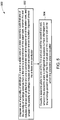
- a method for suppressing surface discharges on a plurality of windings of a stator assembly includes disposing one of the plurality of windings in a slot in a stator core of the stator assembly such that the plurality of windings extends from a first end to a second end of the stator core, where the slot includes a first slot exit at the first end and a second slot exit at the second end of the stator core, and where the plurality of windings includes at least one conductor and an insulation disposed around the at least one conductor.
- the method includes coupling a dielectric plate to one of the first slot exit and the second slot exit, where the dielectric plate is configured to suppress surface discharges on the windings present at one of the first slot exit and the second slot exit to which the dielectric plate is coupled.
- the terms “may” and “may be” indicate a possibility of an occurrence within a set of circumstances; a possession of a specified property, characteristic or function; and/or qualify another verb by expressing one or more of an ability, capability, or possibility associated with the qualified verb. Accordingly, usage of "may” and “may be” indicates that a modified term is apparently appropriate, capable, or suitable for an indicated capacity, function, or usage, while considering that in some circumstances, the modified term may sometimes not be appropriate, capable, or suitable.
- the threshold pressure value may be in a range from about 14.5 psi to about 1 psi. In another example, the altitude may be about 50,000 feet above the sea level. It may be noted that the electric machine may include other components, such as a rotor assembly and a shaft, and is not limited to the stator assembly 100.
- the stator assembly 100 is fixedly mounted relative to a rotor assembly (shown in FIG. 4 ) within a housing of the electric machine.
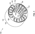
- the stator assembly 100 includes a stator core 102 and a plurality of windings 104. It may be noted that the windings are representative of electrically insulated conductors made into coils of many turns.
- the stator core 102 may be an annular structure with a large central opening. In one example, the annular structure may be formed from a magnetic material. Further, the stator core 102 includes a plurality of slots 106 that extend between a first end 108 and a second end 110 of the stator core 102.
- these slots 106 may be arranged axially over an inner periphery of the annular structure of the stator core 102.
- each of these slots 106 includes a first slot exit 112 at the first end 108 and a second slot exit 114 at the second end 110 of the stator core 102. It may be noted that the length, number, and position of the slots 106 may vary depending upon number of poles in the electric machine, power rating of the electric machine, number of phases, and so forth.
- the windings 104 are disposed in these slots 106 of the stator core 102 and extend from the first slot exit 112 to the second slot exit 114.
- the windings 104 may be laced through the slots 106 to form a winding pattern or configuration in the stator core 102.
- the windings 104 in one slot 106 may be interconnected with the windings 104 in another slot 106 to form a winding pattern or configuration in the stator core 102.
- the windings 104 may form interfaces with the stator core 102 and air at the first slot exit 112 and the second slot exit 114. It may be noted that a point of interface of the windings 104, the stator core 102, and air is referred to as a first interface point (see FIG. 2 ).
- the windings 104 may include one or more conductors 116 and an insulation 118 disposed around the conductors 116.
- the conductors 116 are used for conducting electric current, while the insulation 118 is used for insulating the conductors 116 or high voltage conductors from other potentials.
- each conductor 116 may include a plurality of conductive coil strands that is wrapped by the insulation 118.
- the insulation 118 may be designed to isolate the conductors 116 from the stator core 102.
- the insulation 118 may be used to isolate a conductor 116 in one slot 106 from a conductor 116 in another slot 106 of the stator core 102.
- the windings 104 may have leads that extend through a single end of the stator core 102 or both ends of the stator core 102. Also, these leads may be laced and/or interconnected to form groups and phases of the stator assembly 100. The interconnections may thus allow for a multi-phase operation, while providing a desired number of poles and a suitable winding configuration for the stator assembly 100.
- FIG. 2 illustrates a portion 200 of a typical stator assembly that does not include a dielectric plate.
- the portion 200 of the typical stator assembly depicts windings 204 that extend from a slot exit 212 of a stator core 202, in the typical stator assembly.
- the windings 204 extend through the slot exit 212 at one end of the stator core 202.
- the windings 204 form an interface with the stator core 202 and air.
- a point of interface of the windings 204, the stator core 202, and air is referred to as a first interface point 214.
- the electric field when the electric current flows through the windings 204 in the stator core 202, an electric field is produced around the windings 204.
- the electric machine is operated at a voltage above a threshold voltage value and a pressure below a threshold pressure value, the electric field is substantially increased at the slot exit 212 due to a low dielectric constant value of air and a high dielectric constant value of the stator core 202 at the slot exit 212.
- the electric field may increase at the slot exit 212. This increase in the electric field may cause electrical stress concentration at an area around the slot exit 212, which in-turn causes air breakdown at the slot exit 212.
- the air breakdown is an event where electric current flows through an electrical insulator when voltage applied across the electrical insulator exceeds a breakdown/threshold voltage. The air breakdown results in the electrical insulator becoming electrically conductive.
- the surface discharge is a localized dielectric breakdown (DB) of a small portion of a solid electrical insulation under high voltage (HV) stress. The surface discharge can erode solid electrical insulation and eventually lead to breakdown of the solid electrical insulation.
- the example stator assembly 100 includes a dielectric plate configured to suppress surface discharges on windings 104 at one of the slot exits 112, 114 of slots in a stator core.
- a dielectric plate 120 is provided.
- the dielectric plate 120 is configured to suppress surface discharges on the windings 104 at one of the slot exits 112, 114 of the slots 106 in the stator core 102 of the stator assembly 100. It may be noted that the dielectric plate 120 is capable of suppressing the surface discharges on the windings 104 even when the stator assembly 100 is operated at a pressure below the threshold pressure value and/or at a voltage above the threshold voltage value.
- the stator 1 may include a plurality of dielectric plates 120 that is configured to suppress surface discharges on the windings 104 at each slot exit 112, 114 of the slots 106 in the stator core 102. It may be noted that the dielectric plate 120 may be of any geometry or profile that corresponds to the geometry or profile of the slot exits 112, 114.
- one dielectric plate of the plurality of dielectric plates 120 is mechanically coupled to a corresponding first slot exit 112 and another dielectric plate of the plurality of dielectric plates 120 is mechanically coupled to a corresponding second slot exit 114.
- the windings 104 disposed in the slots 106 may extend through these dielectric plates 120 to form a winding pattern in the stator assembly 100. More specifically, the windings 104 at the first end 108 of the stator core 102 extend through the first slot exit 112 and through the dielectric plate 120 coupled to the first slot exit 112. Similarly, the windings 104 at the second end 110 of the stator core 102 extend through the second slot exit 114 and through the dielectric plate 120 coupled to the second slot exit 114.
- the windings 104 may form interfaces with the dielectric plate 120 and air at the first slot exit 112 and the second slot exit 114. It may be noted that a point of interface of the windings 104, the dielectric plate 120, and air is referred to as a second interface point 302 (see FIG. 3 ).
- the dielectric plates 120 include a corona resistant material selected from the group consisting of a polymer, a mica composite, and a polymer nanocomposite. Also, each dielectric plate 120 has a dielectric constant value that is lower than or proximate to a dielectric constant value of the insulation of the windings 104. In one example, the dielectric constant value of the dielectric plate 120 is in a range from about 4 to about 2. Moreover, each dielectric plate 120 has a predetermined thickness and a predetermined height that aid in reducing the electric field strength on a surface of the windings 104 to a value that is lower than an air breakdown strength. It may be noted that the air breakdown strength is representative of an electric field that causes air to partially ionize and begin conducting. The predetermined thickness may be in a range from about 5 mm to about 20 mm. Similarly, the predetermined height may be in a range from about 10 mm to about 30 mm.
- the dielectric plate 120 may have a predetermined dielectric constant value, the predetermined thickness, and the predetermined height to provide optimum insulation or suppression of the surface discharges at the slot exit 112.
- the predetermined dielectric constant value of the dielectric plate 120 may be in a range from about 4 to about 2 to reduce the electric field by a value that is in a range from about 93% to about 97%.
- FIG. 3 is a diagrammatical representation 300 of a portion of the stator assembly 100 of FIG. 1 . Also, FIG. 3 is described with reference to the components of FIG. 1 . In particular, FIG. 3 depicts the portion 300 of the windings 104 that extend from the slot exit 112 of the stator core 102 and through the dielectric plate 120, in accordance with aspects of the present specification.
- the dielectric plate 120 is mechanically coupled to the slot exit 112.
- the windings 104 extend through the slot exit 112 at one end of the stator core 102 and through the dielectric plate 120 that is coupled to the slot exit 112.
- the windings 104 interface with the dielectric plate 120 and air.
- the point of interface of the windings 104, the dielectric plate 120, and air is referred to as a second interface point 302.
- the electric current flows through the windings that are disposed in the stator core 102. Further, the electric current in the windings 104 produces electric field around the windings 104.
- Use of the dielectric plate 120 at the slot exit 112, 114 aids in reducing the strength of the electric field at the slot exit 112, 114 to a value below the air breakdown strength. In one example, the strength of the electric field may be reduced to a value lower than 240 V/mm, which is about 40% lower than the strength of the electric field at the sea level.
- the electrical stress concentration at a first area around the first interface point 214 of FIG. 2 of the windings 104, the stator core 102, and air is shifted to a second area around the second interface point 302 of FIG. 3 of the windings 104, the dielectric plate 120, and air.
- the dielectric plate 120 has a dielectric constant value that is lower than or proximate to the dielectric constant value of the insulation 118 of the windings 104.
- the stress concentration is shifted from the first interface point 214 to the second interface point 302.
- density of equipotential lines of the electric field at the second interface point 302 is reduced, which in-turn reduces the strength of the electric field and the electrical stress concentration around the second interface point 302.
- this shift in the electrical stress concentration from the first interface point 214 (see FIG. 2 ) to the second interface point 302 (see FIG. 3 ) may substantially reduce surface discharges on the windings 104 at the slot exit 112, 114. As a consequence, the degradation of the insulation 118 and the failure of the electric machine may be prevented or mitigated.
- the electric machine 400 may be an electric motor, an electric generator, or an electromagnetic device.
- the electric motor may be used to convert electric power to mechanical power.
- the electric generator may be used to convert mechanical power to electric power. It may be noted that the configuration and design of the electric machine 400 may vary, and is not limited to the configuration shown in FIG. 4 .
- the electric machine 400 includes a housing 402, a rotor assembly 404, and a stator assembly 406.
- the stator assembly 406 is similar to the stator assembly 100 of FIG. 1 .
- the rotor assembly 404 is supported within the housing 402 and disposed within a central opening of the stator assembly 406.
- the rotor assembly 404 is rotatably coupled to the stator assembly 406. If the electric machine 400 is configured as an electric motor, the rotor assembly 404 is configured to rotate within the stator assembly 406 to transfer mechanical power from the electric machine 400 to a load coupled to the electric machine 400. If the electric machine 400 is configured as an electric generator, the rotor assembly 404 is configured to rotate within the stator assembly 406 to induce electric current in the stator assembly 406, which is further transmitted to a load, such as a power grid.
- stator assembly 406 is fixedly mounted relative to the rotor assembly 404 in the housing 402.
- stator assembly 406 includes a stator core 408 and a plurality of windings 410.
- the stator core 408 includes a plurality of slots that is arranged axially over an inner periphery of the annular structure of the stator core 408. Also, these slots extend axially between a first end 412 and a second end 414 of the stator core 408.
- each of the slots includes a first slot exit 416 at the first end 412 and a second slot exit at the second end 414 of the stator core 408.
- windings 410 are disposed in each of the slots and extend from the first slot exit 416 to the second slot exit. Also, the windings 410 include one or more conductors such as the conductors 116 (see FIG. 1 ) and an insulation such as the insulation 118 (see FIG. 1 ) disposed around the conductors.
- the stator assembly 406 includes a dielectric plate 420 configured to suppress surface discharges on the windings 410 at one of the slot exits 416 of the slots in the stator core 408.
- the stator assembly 406 includes a plurality of dielectric plates 420 that is configured to suppress surface discharges on the windings 410 at each slot exit 416 of the slots in the stator core 408.
- FIG. 6 a graphical representation 600 of an electric field at a first interface point such as the first interface point 214 (see FIG. 2 ) of a typical stator assembly that does not include a dielectric plate, is depicted.
- FIG. 6 is described with reference to FIG. 2 .
- FIG. 6 is a simulation result obtained by using values such as the dielectric constant of the insulation as 4 and the dielectric constant of air as 1.
- the height of the simulated slot exit is considered as 15 mm and the length of the simulated slot exit is considered as 10 mm for generating the simulation results.
- the windings 204 exit the stator core 202 at the slot exit 212 and form an interface with air surrounding the slot exit 212.
- the stator core 202 has a dielectric constant value that is greater than a dielectric constant value of the insulation 218 of the windings 204.
- an electric field 602 at the first interface point 214 has a maximum value.
- a distance between equipotential lines 604 of the electric field 602 is small, which indicates that the equipotential lines 604 are denser at the first interface point 214.
- the density or strength of the electric field 602 at the first interface point 214 is substantially high. In one example, the strength of the electric field 602 is above 240 V/mm.
- the various embodiments of the exemplary systems and methods presented hereinabove aid in suppressing surface discharges on a plurality of windings of a stator assembly.
- By suppressing the surface discharges on the windings degradation of insulation of the conductive windings may be prevented or mitigated, which in turn may prevent failure of the electric machine.
- the example systems and methods enable a compact winding in the stator core, which in turn may reduce the weight of the stator assembly and the electric machine.
- the use of stress grading tapes around the windings may be substantially reduced, which in turn may reduce the manufacturing cost of the stator assembly.
- the exemplary systems and methods may enable the electric machine to operate at high altitudes at low pressure and high voltage without degrading the performance of the electric machine.
Landscapes
- Engineering & Computer Science (AREA)
- Power Engineering (AREA)
- Manufacturing & Machinery (AREA)
- Insulation, Fastening Of Motor, Generator Windings (AREA)
Applications Claiming Priority (1)
| Application Number | Priority Date | Filing Date | Title |
|---|---|---|---|
| US15/933,398 US10693338B2 (en) | 2018-03-23 | 2018-03-23 | System and method for suppressing surface discharges on conductive windings of an electric machine |
Publications (1)
| Publication Number | Publication Date |
|---|---|
| EP3544153A1 true EP3544153A1 (de) | 2019-09-25 |
Family
ID=65904021
Family Applications (1)
| Application Number | Title | Priority Date | Filing Date |
|---|---|---|---|
| EP19163877.4A Pending EP3544153A1 (de) | 2018-03-23 | 2019-03-19 | System und verfahren zur unterdrückung von oberflächenentladungen auf leitenden wicklungen einer elektrischen maschine |
Country Status (4)
| Country | Link |
|---|---|
| US (1) | US10693338B2 (de) |
| EP (1) | EP3544153A1 (de) |
| CN (1) | CN110299781B (de) |
| CA (1) | CA3037551C (de) |
Families Citing this family (4)
| Publication number | Priority date | Publication date | Assignee | Title |
|---|---|---|---|---|
| EP3240150A1 (de) * | 2016-04-25 | 2017-11-01 | Siemens Aktiengesellschaft | Elektrische maschine sowie verfahren zum auseinanderbauen und herstellen der elektrischen maschine |
| US20210367483A1 (en) * | 2020-05-19 | 2021-11-25 | Ge Aviation Systems Llc | Method and system for thermally insulating portions of a stator core |
| US11791684B2 (en) * | 2020-07-02 | 2023-10-17 | Ge Aviation Systems Llc | Method and system for electrically insulating portions of an electric machine |
| CN116683683B (zh) * | 2023-07-27 | 2023-10-31 | 北京金风科创风电设备有限公司 | 定子、发电机、风力发电机组以及防晕处理方法 |
Citations (3)
| Publication number | Priority date | Publication date | Assignee | Title |
|---|---|---|---|---|
| US3679925A (en) * | 1971-02-02 | 1972-07-25 | Westinghouse Electric Corp | Electrical apparatus with corona suppression means |
| US20050088053A1 (en) * | 2003-10-23 | 2005-04-28 | Siemens Westinghouse Power Corporation | Grounding and clamping member for stator coil |
| US20110062816A1 (en) * | 2009-09-16 | 2011-03-17 | Emery Franklin T | Tape Structure with Conductive Outer Side and Electrically Insulating Inner Side |
Family Cites Families (8)
| Publication number | Priority date | Publication date | Assignee | Title |
|---|---|---|---|---|
| SE9602079D0 (sv) | 1996-05-29 | 1996-05-29 | Asea Brown Boveri | Roterande elektriska maskiner med magnetkrets för hög spänning och ett förfarande för tillverkning av densamma |
| US6242825B1 (en) | 1998-11-25 | 2001-06-05 | Hitachi, Ltd. | Electric rotating machine with reduced thickness and volume of insulation |
| DE19963376A1 (de) | 1999-12-28 | 2001-07-12 | Alstom Power Schweiz Ag Baden | Verfahren zur Herstellung einer hochwertigen Isolierung elektrischer Leiter oder Leiterbündel rotierender elektrischer Maschinen mittels Wirbelsintern |
| DE10227226A1 (de) * | 2002-06-18 | 2004-01-15 | Siemens Ag | Glimmschutz |
| US6969940B2 (en) * | 2003-07-08 | 2005-11-29 | Baker Hughes Incorporated | High voltage slot liner for electrical motor |
| JP2005341706A (ja) | 2004-05-27 | 2005-12-08 | Hitachi Ltd | 回転電機 |
| CH698300B1 (de) | 2006-01-24 | 2009-07-15 | Alstom Technology Ltd | Statorwicklung einer rotierenden elektrischen Maschine sowie ein Verfahren zur Herstellung einer solchen Statorwicklung. |
| GB2462257B (en) | 2008-07-29 | 2010-09-29 | Clean Current Power Systems | Electrical machine with dual insulated coil assembly |
-
2018
- 2018-03-23 US US15/933,398 patent/US10693338B2/en active Active
-
2019
- 2019-03-19 EP EP19163877.4A patent/EP3544153A1/de active Pending
- 2019-03-21 CA CA3037551A patent/CA3037551C/en active Active
- 2019-03-22 CN CN201910221654.XA patent/CN110299781B/zh active Active
Patent Citations (3)
| Publication number | Priority date | Publication date | Assignee | Title |
|---|---|---|---|---|
| US3679925A (en) * | 1971-02-02 | 1972-07-25 | Westinghouse Electric Corp | Electrical apparatus with corona suppression means |
| US20050088053A1 (en) * | 2003-10-23 | 2005-04-28 | Siemens Westinghouse Power Corporation | Grounding and clamping member for stator coil |
| US20110062816A1 (en) * | 2009-09-16 | 2011-03-17 | Emery Franklin T | Tape Structure with Conductive Outer Side and Electrically Insulating Inner Side |
Also Published As
| Publication number | Publication date |
|---|---|
| CN110299781B (zh) | 2021-10-29 |
| US10693338B2 (en) | 2020-06-23 |
| CN110299781A (zh) | 2019-10-01 |
| CA3037551A1 (en) | 2019-09-23 |
| US20190296599A1 (en) | 2019-09-26 |
| CA3037551C (en) | 2022-01-18 |
Similar Documents
| Publication | Publication Date | Title |
|---|---|---|
| US11909286B2 (en) | Coil arrangement for an electrical machine | |
| CA3037551C (en) | System and method for suppressing surface discharges on conductive windings of an electric machine | |
| US6226163B1 (en) | Device and method relating to protection of an object against over-currents comprising over-current reduction | |
| AU728661B2 (en) | Insulation for a conductor | |
| JP2001505758A (ja) | 過電流低減および電流制限によって対象物を過電流に対して保護する装置および方法 | |
| KR20000016096A (ko) | 전기모터를 구비한 고압설비_ | |
| CN1226347A (zh) | 电磁装置 | |
| AU9291698A (en) | Electromagnetic device | |
| KR20010032377A (ko) | 고전압 기계 권선용 절연 도체 | |
| EP0935839A1 (de) | Vorrichtung zur überwachung von fehlerströmen in einer rotierenden elektrischen maschine | |
| US11145455B2 (en) | Transformer and an associated method thereof | |
| JP2017118629A (ja) | 回転電機 | |
| US11081923B2 (en) | Corona shielding system for an electrical machine | |
| US9543800B2 (en) | External corona shielding for an electrical machine | |
| US10763005B2 (en) | Insulation for conductors | |
| CN110648825A (zh) | 变压器 | |
| US10862362B2 (en) | Corona shielding system and electrical machine | |
| EP4654223A1 (de) | Elektrische maschine und verfahren zur elektrischen isolierung von abschnitten einer elektrischen maschine | |
| EP4024635A1 (de) | Schaltvorrichtung mit reduzierter teilentladung und verbesserten dreipunkteigenschaften | |
| WO1981003093A1 (fr) | Redresseur haute tension | |
| HK1021083A (en) | Insulated conductor for high-voltage windings and a method of manufacturing the same | |
| JP2000260633A (ja) | 静止誘導電器巻線 | |
| MXPA99005676A (en) | Device and method relating to protection of an object against over-currents comprising over-current reduction | |
| HK1022057A (en) | Electromagnetic device |
Legal Events
| Date | Code | Title | Description |
|---|---|---|---|
| PUAI | Public reference made under article 153(3) epc to a published international application that has entered the european phase |
Free format text: ORIGINAL CODE: 0009012 |
|
| STAA | Information on the status of an ep patent application or granted ep patent |
Free format text: STATUS: THE APPLICATION HAS BEEN PUBLISHED |
|
| AK | Designated contracting states |
Kind code of ref document: A1 Designated state(s): AL AT BE BG CH CY CZ DE DK EE ES FI FR GB GR HR HU IE IS IT LI LT LU LV MC MK MT NL NO PL PT RO RS SE SI SK SM TR |
|
| AX | Request for extension of the european patent |
Extension state: BA ME |
|
| STAA | Information on the status of an ep patent application or granted ep patent |
Free format text: STATUS: REQUEST FOR EXAMINATION WAS MADE |
|
| 17P | Request for examination filed |
Effective date: 20200320 |
|
| RBV | Designated contracting states (corrected) |
Designated state(s): AL AT BE BG CH CY CZ DE DK EE ES FI FR GB GR HR HU IE IS IT LI LT LU LV MC MK MT NL NO PL PT RO RS SE SI SK SM TR |
|
| STAA | Information on the status of an ep patent application or granted ep patent |
Free format text: STATUS: EXAMINATION IS IN PROGRESS |
|
| 17Q | First examination report despatched |
Effective date: 20201214 |