EP3543753A1 - Transceiver hot swap contact structure - Google Patents
Transceiver hot swap contact structure Download PDFInfo
- Publication number
- EP3543753A1 EP3543753A1 EP18213546.7A EP18213546A EP3543753A1 EP 3543753 A1 EP3543753 A1 EP 3543753A1 EP 18213546 A EP18213546 A EP 18213546A EP 3543753 A1 EP3543753 A1 EP 3543753A1
- Authority
- EP
- European Patent Office
- Prior art keywords
- heat
- heat source
- heat sink
- hot swap
- thermal pad
- Prior art date
- Legal status (The legal status is an assumption and is not a legal conclusion. Google has not performed a legal analysis and makes no representation as to the accuracy of the status listed.)
- Granted
Links
Images





Classifications
-
- G—PHYSICS
- G02—OPTICS
- G02B—OPTICAL ELEMENTS, SYSTEMS OR APPARATUS
- G02B6/00—Light guides; Structural details of arrangements comprising light guides and other optical elements, e.g. couplings
- G02B6/24—Coupling light guides
- G02B6/42—Coupling light guides with opto-electronic elements
- G02B6/4201—Packages, e.g. shape, construction, internal or external details
- G02B6/4256—Details of housings
- G02B6/426—Details of housings mounting, engaging or coupling of the package to a board, a frame or a panel
- G02B6/4261—Packages with mounting structures to be pluggable or detachable, e.g. having latches or rails
-
- H—ELECTRICITY
- H01—ELECTRIC ELEMENTS
- H01R—ELECTRICALLY-CONDUCTIVE CONNECTIONS; STRUCTURAL ASSOCIATIONS OF A PLURALITY OF MUTUALLY-INSULATED ELECTRICAL CONNECTING ELEMENTS; COUPLING DEVICES; CURRENT COLLECTORS
- H01R13/00—Details of coupling devices of the kinds covered by groups H01R12/70 or H01R24/00 - H01R33/00
- H01R13/62—Means for facilitating engagement or disengagement of coupling parts or for holding them in engagement
- H01R13/629—Additional means for facilitating engagement or disengagement of coupling parts, e.g. aligning or guiding means, levers, gas pressure electrical locking indicators, manufacturing tolerances
- H01R13/631—Additional means for facilitating engagement or disengagement of coupling parts, e.g. aligning or guiding means, levers, gas pressure electrical locking indicators, manufacturing tolerances for engagement only
-
- F—MECHANICAL ENGINEERING; LIGHTING; HEATING; WEAPONS; BLASTING
- F28—HEAT EXCHANGE IN GENERAL
- F28F—DETAILS OF HEAT-EXCHANGE AND HEAT-TRANSFER APPARATUS, OF GENERAL APPLICATION
- F28F21/00—Constructions of heat-exchange apparatus characterised by the selection of particular materials
- F28F21/04—Constructions of heat-exchange apparatus characterised by the selection of particular materials of ceramic; of concrete; of natural stone
-
- F—MECHANICAL ENGINEERING; LIGHTING; HEATING; WEAPONS; BLASTING
- F28—HEAT EXCHANGE IN GENERAL
- F28F—DETAILS OF HEAT-EXCHANGE AND HEAT-TRANSFER APPARATUS, OF GENERAL APPLICATION
- F28F21/00—Constructions of heat-exchange apparatus characterised by the selection of particular materials
- F28F21/08—Constructions of heat-exchange apparatus characterised by the selection of particular materials of metal
-
- F—MECHANICAL ENGINEERING; LIGHTING; HEATING; WEAPONS; BLASTING
- F28—HEAT EXCHANGE IN GENERAL
- F28F—DETAILS OF HEAT-EXCHANGE AND HEAT-TRANSFER APPARATUS, OF GENERAL APPLICATION
- F28F3/00—Plate-like or laminated elements; Assemblies of plate-like or laminated elements
-
- F—MECHANICAL ENGINEERING; LIGHTING; HEATING; WEAPONS; BLASTING
- F28—HEAT EXCHANGE IN GENERAL
- F28F—DETAILS OF HEAT-EXCHANGE AND HEAT-TRANSFER APPARATUS, OF GENERAL APPLICATION
- F28F5/00—Elements specially adapted for movement
-
- F—MECHANICAL ENGINEERING; LIGHTING; HEATING; WEAPONS; BLASTING
- F28—HEAT EXCHANGE IN GENERAL
- F28F—DETAILS OF HEAT-EXCHANGE AND HEAT-TRANSFER APPARATUS, OF GENERAL APPLICATION
- F28F9/00—Casings; Header boxes; Auxiliary supports for elements; Auxiliary members within casings
- F28F9/007—Auxiliary supports for elements
-
- G—PHYSICS
- G02—OPTICS
- G02B—OPTICAL ELEMENTS, SYSTEMS OR APPARATUS
- G02B6/00—Light guides; Structural details of arrangements comprising light guides and other optical elements, e.g. couplings
- G02B6/24—Coupling light guides
- G02B6/42—Coupling light guides with opto-electronic elements
- G02B6/4201—Packages, e.g. shape, construction, internal or external details
- G02B6/4266—Thermal aspects, temperature control or temperature monitoring
- G02B6/4268—Cooling
- G02B6/4269—Cooling with heat sinks or radiation fins
-
- H—ELECTRICITY
- H01—ELECTRIC ELEMENTS
- H01R—ELECTRICALLY-CONDUCTIVE CONNECTIONS; STRUCTURAL ASSOCIATIONS OF A PLURALITY OF MUTUALLY-INSULATED ELECTRICAL CONNECTING ELEMENTS; COUPLING DEVICES; CURRENT COLLECTORS
- H01R13/00—Details of coupling devices of the kinds covered by groups H01R12/70 or H01R24/00 - H01R33/00
- H01R13/46—Bases; Cases
- H01R13/502—Bases; Cases composed of different pieces
-
- H—ELECTRICITY
- H04—ELECTRIC COMMUNICATION TECHNIQUE
- H04B—TRANSMISSION
- H04B5/00—Near-field transmission systems, e.g. inductive or capacitive transmission systems
- H04B5/40—Near-field transmission systems, e.g. inductive or capacitive transmission systems characterised by components specially adapted for near-field transmission
- H04B5/48—Transceivers
-
- H—ELECTRICITY
- H05—ELECTRIC TECHNIQUES NOT OTHERWISE PROVIDED FOR
- H05K—PRINTED CIRCUITS; CASINGS OR CONSTRUCTIONAL DETAILS OF ELECTRIC APPARATUS; MANUFACTURE OF ASSEMBLAGES OF ELECTRICAL COMPONENTS
- H05K7/00—Constructional details common to different types of electric apparatus
- H05K7/20—Modifications to facilitate cooling, ventilating, or heating
- H05K7/2029—Modifications to facilitate cooling, ventilating, or heating using a liquid coolant with phase change in electronic enclosures
- H05K7/20336—Heat pipes, e.g. wicks or capillary pumps
-
- H—ELECTRICITY
- H05—ELECTRIC TECHNIQUES NOT OTHERWISE PROVIDED FOR
- H05K—PRINTED CIRCUITS; CASINGS OR CONSTRUCTIONAL DETAILS OF ELECTRIC APPARATUS; MANUFACTURE OF ASSEMBLAGES OF ELECTRICAL COMPONENTS
- H05K7/00—Constructional details common to different types of electric apparatus
- H05K7/20—Modifications to facilitate cooling, ventilating, or heating
- H05K7/2039—Modifications to facilitate cooling, ventilating, or heating characterised by the heat transfer by conduction from the heat generating element to a dissipating body
- H05K7/20436—Inner thermal coupling elements in heat dissipating housings, e.g. protrusions or depressions integrally formed in the housing
- H05K7/20445—Inner thermal coupling elements in heat dissipating housings, e.g. protrusions or depressions integrally formed in the housing the coupling element being an additional piece, e.g. thermal standoff
- H05K7/20472—Sheet interfaces
- H05K7/20481—Sheet interfaces characterised by the material composition exhibiting specific thermal properties
-
- H—ELECTRICITY
- H05—ELECTRIC TECHNIQUES NOT OTHERWISE PROVIDED FOR
- H05K—PRINTED CIRCUITS; CASINGS OR CONSTRUCTIONAL DETAILS OF ELECTRIC APPARATUS; MANUFACTURE OF ASSEMBLAGES OF ELECTRICAL COMPONENTS
- H05K7/00—Constructional details common to different types of electric apparatus
- H05K7/20—Modifications to facilitate cooling, ventilating, or heating
- H05K7/2039—Modifications to facilitate cooling, ventilating, or heating characterised by the heat transfer by conduction from the heat generating element to a dissipating body
- H05K7/20436—Inner thermal coupling elements in heat dissipating housings, e.g. protrusions or depressions integrally formed in the housing
- H05K7/2049—Pressing means used to urge contact, e.g. springs
Definitions
- a heat source such as a transceiver, and a heat sink
- a heat sink is joined to provide thermal conduction from the heat source to the heat sink.
- This is provided by allowing the metal surfaces of the heat source and the heat sink to contact each other for transfer of heat.
- this type of contact is imperfect, as the contacting metal surfaces are typically not perfectly flat. Consequently, many portions of the metal surfaces may not be in contact.
- tiny gaps exist between the metal surfaces of the heat source and heat sink, and block heat transfer by conduction in these gaps. The existence of these tiny gaps decreases the heat transfer efficiency between the heat source and heat sink.
- newer technologies have increased the heat output at the heat source up to four times the heat output of previous heat sources. Therefore, there is an ever increasing need to efficiently transfer heat by conduction between the heat source and the heat sink.
- FIG. 1 Prior Art
- FIG. 1 illustrates a heat source 10, having a metal surface 11 to transfer heat by conduction to a heat sink 12, also having a metal surface 13. If surfaces 11 and 13 were to be adjacent to one another, imperfections in the surfaces 11 and 13 would result in a plurality of tiny gaps present between surfaces 11 and 13, thereby reducing conductive heat transfer of heat between these surfaces.
- a thermal pad 14, placed between heat source 10 and heat sink 12 has been proposed. This thermal pad 14 intimately contacts each of metal surface 11 and metal surface 13, thus eliminating or reducing the number of gaps and increasing conductive heat transfer between surfaces 11 and 13.
- FIG. 4 shows, in greater detail, the hot swap mechanism 16.
- a plurality of mounting holes 17, 19 are provided on the hot swap structure 16 to receive fasteners, such as screws (not shown), to mount the hot swap mechanism to a chassis or tray (not shown).
- Hot swap structure 16 comprises a framework 24, including a leading edge 21 and a trailing edge 26. Intermediate the leading edge 21 and trailing edge 26 are provided a plurality of metal pieces 22. A forward end 23 of metal piece 22 is in contact with and secured to leading edge 21 by means of fasteners, such as a rivet 25.
- Leading edge 21 of hot swap structure 16 is chamfered at 28 so as to not impinge upon relatively sliding surfaces during relative movement.
- a plurality of levers 29, 30 are mounted on a shaft 31 secured to framework 24.
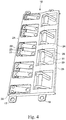
- FIG. 5 is a schematic, bottom of the hot swap structure of FIG. 4 to further illustrate the working structure of the hot swap structure 16.
- the undersides of lever 29, 30 are allowed to contact a leading edge of heat source 10 only after heat source 10 has moved a significant distance towards heat sink 12 and overlies a thermal pad lying beneath the hot swap structure 16.
- the leading edge 37 of heat sink 12 is chamfered 38 so as not to bind with heat source 10 or thermal pad 14 during initial relative movement.
- Metal pieces 22, which are in contact with the leading edge 21 of framework 24 provide the force to urge the heat sink 12 towards heat source 10.
Landscapes
- Engineering & Computer Science (AREA)
- Physics & Mathematics (AREA)
- Thermal Sciences (AREA)
- Microelectronics & Electronic Packaging (AREA)
- Mechanical Engineering (AREA)
- General Engineering & Computer Science (AREA)
- General Physics & Mathematics (AREA)
- Optics & Photonics (AREA)
- Ceramic Engineering (AREA)
- Computer Networks & Wireless Communication (AREA)
- Signal Processing (AREA)
- Cooling Or The Like Of Semiconductors Or Solid State Devices (AREA)
- Cooling Or The Like Of Electrical Apparatus (AREA)
- Optical Couplings Of Light Guides (AREA)
Abstract
Description
- This disclosure relates to the protection of a thermal pad between a heat source and a heat sink where the heat source and heat sink are connected by relative sliding motion. Because of the possibility of damaging the thermal pad during such a connection, a hot swap mechanical structure is employed to prevent damage to the thermal pad when the heat source and heat sink are being joined by relative sliding motion.
- In traditional designs for switch and other networking systems, a heat source, such as a transceiver, and a heat sink, are joined to provide thermal conduction from the heat source to the heat sink. This is provided by allowing the metal surfaces of the heat source and the heat sink to contact each other for transfer of heat. However, it has been found that this type of contact is imperfect, as the contacting metal surfaces are typically not perfectly flat. Consequently, many portions of the metal surfaces may not be in contact. As a result, tiny gaps exist between the metal surfaces of the heat source and heat sink, and block heat transfer by conduction in these gaps. The existence of these tiny gaps decreases the heat transfer efficiency between the heat source and heat sink. At the same time, newer technologies have increased the heat output at the heat source up to four times the heat output of previous heat sources. Therefore, there is an ever increasing need to efficiently transfer heat by conduction between the heat source and the heat sink.
- In some proposed designs, a thermal pad is included between the heat source and heat sink, allowing more intimate contact with the metal surfaces of both the heat source and heat sink. Such a design aims to avoid the existence of the tiny gaps and increase the efficiency of thermal conduction. However, the efficiency of this design relies on maintaining the thermal pad intact. In some cases, this can be difficult. For example, if the heat source and heat sink are joined by relative sliding motion, there is a tendency for damage to the thermal pad during the sliding motion.
- To solve the possibility of damage to the thermal pad, it is a purpose of this disclosure to provide a mechanism to prevent damage to a thermal pad when the heat source and a heat sink with a thermal pad between them are joined by a relative sliding motion.
- It is an object of the present invention to provide a thermal pad between a heat source and a heat sink, which thermal pad is protected, when the heat source and the heat sink are joined by relative motion of these components, such as relative sliding motion, including the provision of a mechanism to prevent protect and prevent damage to the thermal pad during the sliding joinder.
- It is also an object of the present invention to provide a hot swap structure to lift the heat sink contact surface above the thermal pad until the travel between the heat sink and the heat source nears its completion, at which time a lever will force the thermal pad and heat sink into intimate contact with the heat source to improve thermal transfer by conduction.
- It is also an embodiment of the disclosure to provide wheels to assist the lever to force the heat sink and thermal pad into intimate contact with the heat source to increase contact to improve thermal transfer.
- It is a still further embodiment of this disclosure to provide a mechanism which utilizes only a lever structure (without wheels) to cause the heat sink and thermal pad into intimate contact with the heat source to improve heat transfer by conduction.
-
-
FIG. 1 (Prior Art) is a schematic elevation view of a heat source and a heat sink, with a thermal pad interposed between the heat source and heat sink to improve heat transfer by conduction. -
FIG 2 is a schematic, top view of the heat source and the heat sink after being joined by relative sliding motion. -
FIG. 3 is a schematic, side view ofFIG. 2 illustrating the heat source and heat sink joined after relative sliding motion. -
FIG. 4 is a schematic, enlarged perspective view of the hot swap structure ofFIG 2 . -
FIG. 5 is a schematic, bottom view of the hot swap structure ofFIG. 4 . -
FIG. 6 is an enlarged view of the hot swap structure ofFIG. 4 engaged with heat pipes of the heat sink to show detail thereof. -
FIG. 7 is an enlarged, schematic view ofFIG. 3 to show detail. -
FIG. 8 is a further enlarged view ofFIG. 7 to show detail of the forces operating upon the heat contact surface of the heat sink. -
FIG. 9 is a perspective, schematic view of an alternative embodiment of the hot swap structure ofFIG. 4 . -
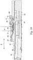
FIG. 10 is an enlarged, cross-sectional view of a joined heat source and heat sink employing the alternative hot swap structure ofFIG. 9 . -
FIG. 11 is an enlarged, partially exploded view of a portion ofFIG. 6 to show detail of theheat source 10 andcage 15. - The present invention is described with reference to the attached figures, where like reference numerals are used throughout the figures to designate similar or equivalent elements. The figures are not drawn to scale and are provided merely to illustrate the instant invention. Several aspects of the invention are described below with reference to example applications for illustration. It should be understood that numerous specific details, relationships, and methods are set forth to provide a full understanding of the invention. Those of ordinary skill in the art will appreciate that not every element is visible in every drawing. One having ordinary skill in the relevant art, however, will readily recognize that the invention can be practiced without one or more of the specific details, or with other methods. In other instances, well-known structures or operations are not shown in detail to avoid obscuring the invention. The present invention is not limited by the illustrated ordering of acts or events, as some acts may occur in different orders and/or concurrently with other acts or events. Furthermore, not all illustrated acts or events are required to implement a methodology in accordance with the present invention.
- As noted above, to solve the possibility of damage to the thermal pad, this disclosure describes a hot swap mechanism to protect and prevent damage to a thermal pad when a heat source and a heat sink are joined by a relative sliding motion or other types of damaging motion. This is achieved by the use of the hot swap mechanism, in cooperation with the heat source, the heat sink and the thermal pad. The hot swap mechanism is actuated by contact of the surface of the sliding heat source with a mechanism, including a lever, or a lever and roller, which upon actuation, applies a downward force to bring the thermal pad into contact with the surface of the heat source.
-
FIG. 1 (Prior Art) illustrates aheat source 10, having ametal surface 11 to transfer heat by conduction to aheat sink 12, also having ametal surface 13. Ifsurfaces surfaces surfaces surfaces thermal pad 14, placed betweenheat source 10 andheat sink 12, has been proposed. Thisthermal pad 14 intimately contacts each ofmetal surface 11 andmetal surface 13, thus eliminating or reducing the number of gaps and increasing conductive heat transfer betweensurfaces -
Thermal pad 14 can be made from various materials having both high thermal conductivity and some resiliency to form a soft, conformal thermal pad to intimatelycontact metal surfaces thermal pad 14 can be made of a silicone polymer that is combined with a thermal medium, such as ceramic. The silicone polymer and ceramic powders are mixed, cast, and cured to sheet form. Different thermal conductivities can be tailored by selecting both the type of silicone polymer and the type and amount of ceramic powders. -
FIG. 2 is a schematic, top view of theheat source 10 and theheat sink 12 after being joined by relative sliding motion, where the relative sliding motion is in the direction shown by arrowB. heat sink 12, may possess a number ofheat pipes body 18 ofheat sink 12 and athermal pad 14 interposed betweenheat source 10 andheat sink 12. -
FIG. 3 is a schematic, side view ofFIG. 2 illustrating the heat source and heat sink joined after relative sliding motion. As shown inFIGs. 2 and3 ,heat sink 12 includes acage 15 and ahot swap structure 16 above thecage 15, the structure and purpose of which is described further below. Cage 15 assists in the alignment of both vertical and horizontal directions when theheat source 10 andheat sink 12 are joined as shown inFIG. 3 after the relative sliding motion. -
FIG. 4 shows, in greater detail, thehot swap mechanism 16. A plurality ofmounting holes hot swap structure 16 to receive fasteners, such as screws (not shown), to mount the hot swap mechanism to a chassis or tray (not shown).Hot swap structure 16 comprises aframework 24, including a leadingedge 21 and atrailing edge 26. Intermediate the leadingedge 21 andtrailing edge 26 are provided a plurality ofmetal pieces 22. A forward end 23 ofmetal piece 22 is in contact with and secured to leadingedge 21 by means of fasteners, such as arivet 25. Leadingedge 21 ofhot swap structure 16 is chamfered at 28 so as to not impinge upon relatively sliding surfaces during relative movement. A plurality oflevers shaft 31 secured toframework 24.Shaft 31 permits a pivoting rotation of each of the plurality oflevers heat source 10 contacts an underside of each of the plurality oflevers leading edge 21 away from thethermal pad 14 as to not damage the same whenheat source 10 andheat sink 12 are initially moved towards one another in relative sliding motion. However, upon significant movement of theheat sink 12 andheat source 10 towards one another, theheat source 10 comes into contact with the underside of each of the plurality oflevers levers hot swap structure 16 causes a pivoting motion of each of the plurality oflevers metal pieces 22 to force the leadingedge 21 and other parts offramework 24 into firm contact withthermal pad 14 and create a gap-free contact for conductive heat transfer betweenheat source 10 andheat sink 12. -
FIG. 5 is a schematic, bottom of the hot swap structure ofFIG. 4 to further illustrate the working structure of thehot swap structure 16. As shown inFIG. 5 , the undersides oflever heat source 10 only afterheat source 10 has moved a significant distance towardsheat sink 12 and overlies a thermal pad lying beneath thehot swap structure 16. The leadingedge 37 ofheat sink 12 is chamfered 38 so as not to bind withheat source 10 orthermal pad 14 during initial relative movement.Metal pieces 22, which are in contact with the leadingedge 21 offramework 24 provide the force to urge theheat sink 12 towardsheat source 10. -
FIG. 6 is an enlarged view of thehot swap structure 16 ofFIG. 4 engaged withheat pipes heat sink 12 to show detail thereof.Cage 15, clearly visible inFIG. 6 acts as a guide to assure alignment between heat source 10 (only a single unit of which is shown inFIG. 6 for clarity) andheat sink 12 as well ashot swap structure 16.Heat sink 12 can have aforward component 42, directly in contact withheat pipes heat source 10 andheat sink 12. Alternatively,forward component 42 can connect directly tobody 18 ofheat sink 12 to effect the conductive heat transfer. -
FIG. 7 is an enlarged, schematic view ofFIG. 3 to show detail.FIG. 7 shows the initial engagement ofheat source 10 withheat sink 12, and the interaction ofhot swap structure 16 with theseelements heat source 10 withheat sink 12 by relative sliding motion in direction of Arrow B inFIG. 7 ,lever 29 sits in a void or groove incage 15 until the upper surface ofheat source 10 contacts thelever 29, as shown inFIG. 7 .Thermal pad 14 is not pressed against upper surface ofheat source 10 at this stage of movement. Upon contact ofmetal surface 11 withlever 29, lever 29 exhibits an upward force in direction ofArrow F. Lever 29 pivots aboutshaft 31, causing a downward force in the direction of Arrow G to be applied to trailingedge 26 ofmetal piece 22. This downward force in the direction of Arrow G applies force uponthermal pad 14 to force it into intimate contact with upper surface ofheat source 10. Simultaneously, a downward force in the direction of Arrow H is applied toframework 24. This downward force in direction of Arrow H forces theheat sink 12 into intimate engagement withthermal pad 14 assuring excellent heat conductivity between the upper surface ofheat source 10 andheat sink 12, through the intimate contact of each of these surfaces withthermal pad 14. -
FIG. 8 is a further enlarged view ofFIG. 7 to show detail of the forces operating upon the heat contact surface of theheat sink 12. InFIG. 8 ,lever 29 if lifted by its contact with upper surface ofheat source 10. This lifting in the direction of arrow F, creates force G, as a result of the pivot oflever 29 aboutshaft 31, causing one of the plurality ofmetal pieces 22 to impinge on leadingedge 21 offramework 24. Simultaneously, an additional force in the direction of arrow H pushes the bottom ofmetal pieces 22 into contact with the forward component ofheat sink 12 to bring it into direct contact withthermal pad 14 assuring direct conductive transfer betweenheat source 10 andheat sink 12. Leadingedge 37 ofheat sink 12 is beveled at 38 so as not to impinge uponthermal pad 14, or any other element, during the relative sliding motion. -
FIG. 9 is a perspective, schematic view of an alternative embodiment of the hot swap structure ofFIG. 4 . InFIG. 9 , each of the rear edges of thelevers 29 are provided with awheel 49.Wheel 49 rides in a gap or groove incage 15.Lever 29 rests upon therear edge 46 ofmetal piece 22. - As shown in
FIG. 10 , asheat source 10 becomes more fully engaged withcage 15wheel 49 lifts up onto upper surface ofheat source 10 in the direction of Arrow C. This lifting in the direction of arrow C causeslever 29 to create a downward force in the direction of Arrow D. This downward force in the direction of Arrow D causes themetal piece 22 to force the leadingedge 21 offramework 24 into intimate contact withthermal pad 14 against upper surface ofheat source 10. Simultaneously, a downward force in the direction of Arrow E acts upon theframework 24. This downward force againstframework 24 acts to bring theforward component 42 ofheat sink 12 into contact withthermal pad 14. This contact betweencomponent 42 ofheat sink 12 andthermal pad 14 assures good thermal conduction betweenheat source 10 andheat sink 12 throughthermal pad 14. -
FIG. 11 is an enlarged, partially exploded view of a portion ofFIG. 6 to show detail of theheat source 10 andcage 15. Clearly shown are the openings orgrooves cage 15 to permit thelevers 29, 30 (or alternatively the wheels 49) to pass through the cage to contact theupper surface 9 ofheat source 10. - As
heat source 10 can be mentioned transceivers, and similar elements. The sliding motion to join the heat source and heat sink can be in the horizontal direction. Any type of device that has a sliding connection can find benefit from the disclosure herein. Included in such devices are hard disk drives ("HDD") and solid state drives ("SSD").
Claims (15)
- A hot swap structure (16) for transferring heat between a heat source (10) and a heat sink (12) comprising:a metal piece (22);a lever (29, 30), the lever being mounted to be operatively engageable with the
metal piece (22); anda framework (24) for supporting the lever (29, 30) and the metal piece (22);wherein relative sliding motion between the heat source (10) and the heat sink (12) actuates the lever (29, 30) to urge a thermal pad (14) into contact with the heat source (10). - The hot swap structure (16) of claim 1, further comprising a wheel (49) at an end of the lever (29, 30).
- The hot swap structure (16) of claim 1, further comprising a cage (15) to guide the heat source (10) and the heat sink (12) during the relative sliding motion.
- The hot swap structure (16) of claim 3, further comprising a groove or void (50, 51) in the cage (15) in which the lever (29, 30) rests.
- The hot swap structure (16) of claim 1, wherein the thermal pad (14) comprises a polymer filled with ceramic particles.
- The hot swap structure (16) of claim 1, wherein the hot swap structure (16) further comprises a plurality of heat sources (10) and a plurality of heat sinks (12).
- The hot swap structure (16) of claim 1, further comprising a leading edge (23) on the metal piece (22), and the actuation of the lever (29, 30) also causes the leading edge (23) to exert a force on the framework (24) to cause the framework (24) to urge the heat sink (12) into intimate contact with the thermal pad (14).
- A heat transfer system between a heat source (10) and a heat sink (12) comprising:a thermal pad (14) between the heat source (10) and the heat sink (12), wherein the heat source (10) and the heat sink (12) are joined by relative sliding motion; anda hot swap structure (16) to urge the thermal pad (14) into contact with the heat source (10) and simultaneously urge the heat sink (12) into contact with the thermal pad (14); the hot swap structure (16) comprising a framework (24), the framework (24) holding a plurality of metal pieces (22), the trailing edge (46) of each of the metal pieces (22) in contact with a lever (29, 30).
- The heat transfer system of claim 8, wherein each lever (29, 30) has a wheel (49) at its trailing edge.
- The heat transfer system of claim 8, further including a cage (15) to align the heat source (10) and heat sink (12).
- The heat transfer system of claim 8, wherein the lever (29, 30) is actuated by contact with the relatively moving heat source (10).
- The heat transfer system of claim 8, wherein the heat source (10) is a transceiver.
- The heat transfer system of claim 10, wherein the cage (15) defines a void (50, 51) in which the lever (29, 30) rests until actuated by contact with the relatively moving heat source (10).
- The heat transfer system of claim 8, further comprising a cage (15), wherein the cage (15) defines a groove (50, 51) in which the wheel (49) rests until actuated by contact with the relatively moving heat source (10).
- The heat transfer system of claim 8, wherein the thermal pad (14) comprises a polymer filed with ceramic particles.
Applications Claiming Priority (2)
| Application Number | Priority Date | Filing Date | Title |
|---|---|---|---|
| US201862646522P | 2018-03-22 | 2018-03-22 | |
| US16/058,408 US10651598B2 (en) | 2018-03-22 | 2018-08-08 | Transceiver hot swap contact structure |
Publications (2)
| Publication Number | Publication Date |
|---|---|
| EP3543753A1 true EP3543753A1 (en) | 2019-09-25 |
| EP3543753B1 EP3543753B1 (en) | 2024-04-10 |
Family
ID=65009521
Family Applications (1)
| Application Number | Title | Priority Date | Filing Date |
|---|---|---|---|
| EP18213546.7A Active EP3543753B1 (en) | 2018-03-22 | 2018-12-18 | Transceiver hot swap contact structure |
Country Status (5)
| Country | Link |
|---|---|
| US (1) | US10651598B2 (en) |
| EP (1) | EP3543753B1 (en) |
| JP (1) | JP6812470B2 (en) |
| CN (1) | CN110296628B (en) |
| TW (1) | TWI679665B (en) |
Cited By (2)
| Publication number | Priority date | Publication date | Assignee | Title |
|---|---|---|---|---|
| US11589481B2 (en) * | 2020-08-14 | 2023-02-21 | Cisco Technology, Inc. | Heat sink assembly for electronic equipment |
| US12069794B2 (en) | 2022-07-06 | 2024-08-20 | Cisco Technology, Inc. | Dynamic control of heat sink pressure |
Families Citing this family (6)
| Publication number | Priority date | Publication date | Assignee | Title |
|---|---|---|---|---|
| US11271348B1 (en) * | 2018-10-24 | 2022-03-08 | Amphenol Corporation | High performance electrical connector |
| KR102749360B1 (en) | 2019-09-17 | 2024-12-31 | 캐논 가부시끼가이샤 | Toner cartridge with return absence and toner discharge pump |
| WO2021249640A1 (en) * | 2020-06-10 | 2021-12-16 | Telefonaktiebolaget Lm Ericsson (Publ) | A connector system |
| TWI753695B (en) * | 2020-12-10 | 2022-01-21 | 台灣莫仕股份有限公司 | connector assembly |
| CN114623722B (en) * | 2020-12-10 | 2025-05-27 | 莫列斯有限公司 | Connector components |
| CN218867463U (en) * | 2022-11-04 | 2023-04-14 | 莫列斯有限公司 | Connector assembly |
Citations (1)
| Publication number | Priority date | Publication date | Assignee | Title |
|---|---|---|---|---|
| US20090296351A1 (en) * | 2007-12-11 | 2009-12-03 | Sumitomo Electric Industries, Ltd. | Mechanism to make a heat sink in contact with a pluggable transceiver, a pluggable optical transceiver and a cage assembly providing the same |
Family Cites Families (26)
| Publication number | Priority date | Publication date | Assignee | Title |
|---|---|---|---|---|
| JPS63105847A (en) | 1986-10-23 | 1988-05-11 | Nippon Telegr & Teleph Corp <Ntt> | Assembly device for optical connector |
| US5241453A (en) * | 1991-11-18 | 1993-08-31 | The Whitaker Corporation | EMI shielding device |
| US5785535A (en) * | 1996-01-17 | 1998-07-28 | International Business Machines Corporation | Computer system with surface mount socket |
| JP3881488B2 (en) * | 1999-12-13 | 2007-02-14 | 株式会社東芝 | Circuit module cooling device and electronic apparatus having the cooling device |
| US6254423B1 (en) * | 2001-01-04 | 2001-07-03 | Chin-Feng Lin | Power diode terminal holder mounting arrangement |
| US6547580B1 (en) * | 2001-09-24 | 2003-04-15 | Texas Instruments Incorporated | Socket apparatus particularly adapted for land grid array type semiconductor devices |
| US6490161B1 (en) * | 2002-01-08 | 2002-12-03 | International Business Machines Corporation | Peripheral land grid array package with improved thermal performance |
| US6988871B2 (en) | 2002-05-06 | 2006-01-24 | Tyco Electronics Canada Ltd. | Heat sink attachment clip |
| US7280362B2 (en) * | 2003-12-04 | 2007-10-09 | Dell Products L.P. | Method and apparatus for attaching a processor and corresponding heat sink to a circuit board |
| JP4073439B2 (en) * | 2004-04-16 | 2008-04-09 | 山一電機株式会社 | Socket for semiconductor device |
| CN1987727A (en) * | 2005-12-22 | 2007-06-27 | 佛山市顺德区顺达电脑厂有限公司 | Heat radiation module |
| JP2009092748A (en) | 2007-10-04 | 2009-04-30 | Opnext Japan Inc | Optical transmission module and optical transmission module assembly |
| CN201113135Y (en) * | 2007-10-23 | 2008-09-10 | 富士康(昆山)电脑接插件有限公司 | Electrical Connector Assembly |
| US7866043B2 (en) | 2008-04-28 | 2011-01-11 | Golden Sun News Techniques Co., Ltd. | Method of flatting evaporating section of heat pipe embedded in heat dissipation device |
| CN101608757B (en) | 2009-07-06 | 2011-07-27 | 南京中压光电科技有限公司 | LED streetlight |
| JP2011158584A (en) * | 2010-01-29 | 2011-08-18 | Sumitomo Electric Ind Ltd | Optical data link |
| WO2011120188A1 (en) * | 2010-03-29 | 2011-10-06 | Telefonaktiebolaget L M Ericsson (Publ) | Cooling device for pluggable module, assembly of the cooling device and the pluggable module |
| WO2011159599A2 (en) * | 2010-06-15 | 2011-12-22 | Molex Incorporated | Cage, receptacle and system for use therewith |
| JP5719566B2 (en) * | 2010-11-04 | 2015-05-20 | 新光電気工業株式会社 | IC package heat sink and IC package connection device having heat sink |
| US8885342B2 (en) * | 2010-12-29 | 2014-11-11 | Methode Electronics, Inc. | Thermal management for electronic device housing |
| CN201928573U (en) * | 2011-01-05 | 2011-08-10 | 广达电脑股份有限公司 | Cooling module |
| JP2012145617A (en) * | 2011-01-07 | 2012-08-02 | Sumitomo Electric Ind Ltd | Optical module |
| US20130157499A1 (en) * | 2011-12-20 | 2013-06-20 | International Business Machines Corporation | Active electrical connection with self-engaging, self-releasing heat-sink |
| US9681556B2 (en) * | 2012-09-28 | 2017-06-13 | Intel Corporation | Contact protection for integrated circuit device loading |
| US8911244B2 (en) * | 2012-12-13 | 2014-12-16 | International Business Machines Corporation | Receptacle with heat management for electronic and optical systems |
| TWI591311B (en) | 2015-06-26 | 2017-07-11 | Yuan-Nan Zhu | Aquarium breeding water cooling module |
-
2018
- 2018-08-08 US US16/058,408 patent/US10651598B2/en active Active
- 2018-10-23 TW TW107137407A patent/TWI679665B/en active
- 2018-11-08 CN CN201811323387.9A patent/CN110296628B/en active Active
- 2018-12-18 EP EP18213546.7A patent/EP3543753B1/en active Active
-
2019
- 2019-01-09 JP JP2019002114A patent/JP6812470B2/en active Active
Patent Citations (1)
| Publication number | Priority date | Publication date | Assignee | Title |
|---|---|---|---|---|
| US20090296351A1 (en) * | 2007-12-11 | 2009-12-03 | Sumitomo Electric Industries, Ltd. | Mechanism to make a heat sink in contact with a pluggable transceiver, a pluggable optical transceiver and a cage assembly providing the same |
Cited By (3)
| Publication number | Priority date | Publication date | Assignee | Title |
|---|---|---|---|---|
| US11589481B2 (en) * | 2020-08-14 | 2023-02-21 | Cisco Technology, Inc. | Heat sink assembly for electronic equipment |
| US12349318B2 (en) | 2020-08-14 | 2025-07-01 | Cisco Technology, Inc. | Heat sink assembly for electronic equipment |
| US12069794B2 (en) | 2022-07-06 | 2024-08-20 | Cisco Technology, Inc. | Dynamic control of heat sink pressure |
Also Published As
| Publication number | Publication date |
|---|---|
| JP2019168214A (en) | 2019-10-03 |
| TWI679665B (en) | 2019-12-11 |
| CN110296628B (en) | 2021-04-06 |
| US10651598B2 (en) | 2020-05-12 |
| JP6812470B2 (en) | 2021-01-13 |
| TW201941239A (en) | 2019-10-16 |
| EP3543753B1 (en) | 2024-04-10 |
| CN110296628A (en) | 2019-10-01 |
| US20190296486A1 (en) | 2019-09-26 |
Similar Documents
| Publication | Publication Date | Title |
|---|---|---|
| EP3543753B1 (en) | Transceiver hot swap contact structure | |
| JP4998249B2 (en) | Optical transceiver heat dissipation device | |
| CN107833855B (en) | Workpiece referencing system and method for referencing workpieces supported by a workpiece carrier | |
| JPH1013099A (en) | Circuit board holding device and circuit board holding release method | |
| KR101918118B1 (en) | Mounting device | |
| US20090300903A1 (en) | Mounting apparatus for heat sink | |
| JPH0723733B2 (en) | Disc brake pad fallout prevention device | |
| EP3657539A1 (en) | Method and device for simultaneously bonding multiple chips of different heights on a flexible substrate using anisotropic conductive film or paste | |
| US9345171B2 (en) | Heat sink retainer unit and thermal module device | |
| JP2014110364A (en) | Feed mechanism | |
| JP6052523B1 (en) | Non-powered transfer device | |
| JP6336510B2 (en) | Pressurizing method and pressurizing apparatus | |
| KR101162732B1 (en) | Friction Pads for Brake Systems | |
| TWM659543U (en) | Gripper mechanism | |
| CN101875460B (en) | Brake device for an elevator and elevator device | |
| CN102586752A (en) | Substrate fixing device | |
| CN216334769U (en) | Positioning mechanism is transported to fin | |
| CN105839531A (en) | An expansion joint covering device for municipal bridges | |
| CN206639781U (en) | Semiconductor Package Constraints | |
| CN105839526B (en) | A kind of covered structure of bridge expanssion joint | |
| CN112291921A (en) | Embedded laminated structure of metal substrate | |
| CN105735125B (en) | A kind of denotable bridge expanssion joint covered structure | |
| CN108857304B (en) | Plug-in components snatchs tool | |
| CN105839525A (en) | Bridge expansion joint covering device flexible to use | |
| CN201711849U (en) | Transmission system of polishing machine |
Legal Events
| Date | Code | Title | Description |
|---|---|---|---|
| PUAI | Public reference made under article 153(3) epc to a published international application that has entered the european phase |
Free format text: ORIGINAL CODE: 0009012 |
|
| STAA | Information on the status of an ep patent application or granted ep patent |
Free format text: STATUS: THE APPLICATION HAS BEEN PUBLISHED |
|
| AK | Designated contracting states |
Kind code of ref document: A1 Designated state(s): AL AT BE BG CH CY CZ DE DK EE ES FI FR GB GR HR HU IE IS IT LI LT LU LV MC MK MT NL NO PL PT RO RS SE SI SK SM TR |
|
| AX | Request for extension of the european patent |
Extension state: BA ME |
|
| STAA | Information on the status of an ep patent application or granted ep patent |
Free format text: STATUS: REQUEST FOR EXAMINATION WAS MADE |
|
| 17P | Request for examination filed |
Effective date: 20191223 |
|
| RBV | Designated contracting states (corrected) |
Designated state(s): AL AT BE BG CH CY CZ DE DK EE ES FI FR GB GR HR HU IE IS IT LI LT LU LV MC MK MT NL NO PL PT RO RS SE SI SK SM TR |
|
| STAA | Information on the status of an ep patent application or granted ep patent |
Free format text: STATUS: EXAMINATION IS IN PROGRESS |
|
| 17Q | First examination report despatched |
Effective date: 20200903 |
|
| GRAP | Despatch of communication of intention to grant a patent |
Free format text: ORIGINAL CODE: EPIDOSNIGR1 |
|
| STAA | Information on the status of an ep patent application or granted ep patent |
Free format text: STATUS: GRANT OF PATENT IS INTENDED |
|
| INTG | Intention to grant announced |
Effective date: 20231218 |
|
| GRAS | Grant fee paid |
Free format text: ORIGINAL CODE: EPIDOSNIGR3 |
|
| GRAA | (expected) grant |
Free format text: ORIGINAL CODE: 0009210 |
|
| STAA | Information on the status of an ep patent application or granted ep patent |
Free format text: STATUS: THE PATENT HAS BEEN GRANTED |
|
| AK | Designated contracting states |
Kind code of ref document: B1 Designated state(s): AL AT BE BG CH CY CZ DE DK EE ES FI FR GB GR HR HU IE IS IT LI LT LU LV MC MK MT NL NO PL PT RO RS SE SI SK SM TR |
|
| REG | Reference to a national code |
Ref country code: GB Ref legal event code: FG4D |
|
| REG | Reference to a national code |
Ref country code: CH Ref legal event code: EP |
|
| REG | Reference to a national code |
Ref country code: DE Ref legal event code: R096 Ref document number: 602018067798 Country of ref document: DE |
|
| REG | Reference to a national code |
Ref country code: IE Ref legal event code: FG4D |
|
| REG | Reference to a national code |
Ref country code: LT Ref legal event code: MG9D |
|
| REG | Reference to a national code |
Ref country code: NL Ref legal event code: MP Effective date: 20240410 |
|
| REG | Reference to a national code |
Ref country code: AT Ref legal event code: MK05 Ref document number: 1675474 Country of ref document: AT Kind code of ref document: T Effective date: 20240410 |
|
| PG25 | Lapsed in a contracting state [announced via postgrant information from national office to epo] |
Ref country code: NL Free format text: LAPSE BECAUSE OF FAILURE TO SUBMIT A TRANSLATION OF THE DESCRIPTION OR TO PAY THE FEE WITHIN THE PRESCRIBED TIME-LIMIT Effective date: 20240410 |
|
| PG25 | Lapsed in a contracting state [announced via postgrant information from national office to epo] |
Ref country code: NL Free format text: LAPSE BECAUSE OF FAILURE TO SUBMIT A TRANSLATION OF THE DESCRIPTION OR TO PAY THE FEE WITHIN THE PRESCRIBED TIME-LIMIT Effective date: 20240410 |
|
| PG25 | Lapsed in a contracting state [announced via postgrant information from national office to epo] |
Ref country code: IS Free format text: LAPSE BECAUSE OF FAILURE TO SUBMIT A TRANSLATION OF THE DESCRIPTION OR TO PAY THE FEE WITHIN THE PRESCRIBED TIME-LIMIT Effective date: 20240810 |
|
| PG25 | Lapsed in a contracting state [announced via postgrant information from national office to epo] |
Ref country code: BG Free format text: LAPSE BECAUSE OF FAILURE TO SUBMIT A TRANSLATION OF THE DESCRIPTION OR TO PAY THE FEE WITHIN THE PRESCRIBED TIME-LIMIT Effective date: 20240410 |
|
| PG25 | Lapsed in a contracting state [announced via postgrant information from national office to epo] |
Ref country code: HR Free format text: LAPSE BECAUSE OF FAILURE TO SUBMIT A TRANSLATION OF THE DESCRIPTION OR TO PAY THE FEE WITHIN THE PRESCRIBED TIME-LIMIT Effective date: 20240410 Ref country code: FI Free format text: LAPSE BECAUSE OF FAILURE TO SUBMIT A TRANSLATION OF THE DESCRIPTION OR TO PAY THE FEE WITHIN THE PRESCRIBED TIME-LIMIT Effective date: 20240410 |
|
| PG25 | Lapsed in a contracting state [announced via postgrant information from national office to epo] |
Ref country code: GR Free format text: LAPSE BECAUSE OF FAILURE TO SUBMIT A TRANSLATION OF THE DESCRIPTION OR TO PAY THE FEE WITHIN THE PRESCRIBED TIME-LIMIT Effective date: 20240711 |
|
| PG25 | Lapsed in a contracting state [announced via postgrant information from national office to epo] |
Ref country code: PT Free format text: LAPSE BECAUSE OF FAILURE TO SUBMIT A TRANSLATION OF THE DESCRIPTION OR TO PAY THE FEE WITHIN THE PRESCRIBED TIME-LIMIT Effective date: 20240812 |
|
| PG25 | Lapsed in a contracting state [announced via postgrant information from national office to epo] |
Ref country code: ES Free format text: LAPSE BECAUSE OF FAILURE TO SUBMIT A TRANSLATION OF THE DESCRIPTION OR TO PAY THE FEE WITHIN THE PRESCRIBED TIME-LIMIT Effective date: 20240410 |
|
| PG25 | Lapsed in a contracting state [announced via postgrant information from national office to epo] |
Ref country code: AT Free format text: LAPSE BECAUSE OF FAILURE TO SUBMIT A TRANSLATION OF THE DESCRIPTION OR TO PAY THE FEE WITHIN THE PRESCRIBED TIME-LIMIT Effective date: 20240410 |
|
| PG25 | Lapsed in a contracting state [announced via postgrant information from national office to epo] |
Ref country code: PL Free format text: LAPSE BECAUSE OF FAILURE TO SUBMIT A TRANSLATION OF THE DESCRIPTION OR TO PAY THE FEE WITHIN THE PRESCRIBED TIME-LIMIT Effective date: 20240410 |
|
| PG25 | Lapsed in a contracting state [announced via postgrant information from national office to epo] |
Ref country code: LV Free format text: LAPSE BECAUSE OF FAILURE TO SUBMIT A TRANSLATION OF THE DESCRIPTION OR TO PAY THE FEE WITHIN THE PRESCRIBED TIME-LIMIT Effective date: 20240410 |
|
| PG25 | Lapsed in a contracting state [announced via postgrant information from national office to epo] |
Ref country code: PT Free format text: LAPSE BECAUSE OF FAILURE TO SUBMIT A TRANSLATION OF THE DESCRIPTION OR TO PAY THE FEE WITHIN THE PRESCRIBED TIME-LIMIT Effective date: 20240812 Ref country code: PL Free format text: LAPSE BECAUSE OF FAILURE TO SUBMIT A TRANSLATION OF THE DESCRIPTION OR TO PAY THE FEE WITHIN THE PRESCRIBED TIME-LIMIT Effective date: 20240410 Ref country code: NO Free format text: LAPSE BECAUSE OF FAILURE TO SUBMIT A TRANSLATION OF THE DESCRIPTION OR TO PAY THE FEE WITHIN THE PRESCRIBED TIME-LIMIT Effective date: 20240710 Ref country code: LV Free format text: LAPSE BECAUSE OF FAILURE TO SUBMIT A TRANSLATION OF THE DESCRIPTION OR TO PAY THE FEE WITHIN THE PRESCRIBED TIME-LIMIT Effective date: 20240410 Ref country code: IS Free format text: LAPSE BECAUSE OF FAILURE TO SUBMIT A TRANSLATION OF THE DESCRIPTION OR TO PAY THE FEE WITHIN THE PRESCRIBED TIME-LIMIT Effective date: 20240810 Ref country code: HR Free format text: LAPSE BECAUSE OF FAILURE TO SUBMIT A TRANSLATION OF THE DESCRIPTION OR TO PAY THE FEE WITHIN THE PRESCRIBED TIME-LIMIT Effective date: 20240410 Ref country code: GR Free format text: LAPSE BECAUSE OF FAILURE TO SUBMIT A TRANSLATION OF THE DESCRIPTION OR TO PAY THE FEE WITHIN THE PRESCRIBED TIME-LIMIT Effective date: 20240711 Ref country code: FI Free format text: LAPSE BECAUSE OF FAILURE TO SUBMIT A TRANSLATION OF THE DESCRIPTION OR TO PAY THE FEE WITHIN THE PRESCRIBED TIME-LIMIT Effective date: 20240410 Ref country code: ES Free format text: LAPSE BECAUSE OF FAILURE TO SUBMIT A TRANSLATION OF THE DESCRIPTION OR TO PAY THE FEE WITHIN THE PRESCRIBED TIME-LIMIT Effective date: 20240410 Ref country code: BG Free format text: LAPSE BECAUSE OF FAILURE TO SUBMIT A TRANSLATION OF THE DESCRIPTION OR TO PAY THE FEE WITHIN THE PRESCRIBED TIME-LIMIT Effective date: 20240410 Ref country code: AT Free format text: LAPSE BECAUSE OF FAILURE TO SUBMIT A TRANSLATION OF THE DESCRIPTION OR TO PAY THE FEE WITHIN THE PRESCRIBED TIME-LIMIT Effective date: 20240410 Ref country code: RS Free format text: LAPSE BECAUSE OF FAILURE TO SUBMIT A TRANSLATION OF THE DESCRIPTION OR TO PAY THE FEE WITHIN THE PRESCRIBED TIME-LIMIT Effective date: 20240710 |
|
| REG | Reference to a national code |
Ref country code: DE Ref legal event code: R097 Ref document number: 602018067798 Country of ref document: DE |
|
| PG25 | Lapsed in a contracting state [announced via postgrant information from national office to epo] |
Ref country code: DK Free format text: LAPSE BECAUSE OF FAILURE TO SUBMIT A TRANSLATION OF THE DESCRIPTION OR TO PAY THE FEE WITHIN THE PRESCRIBED TIME-LIMIT Effective date: 20240410 |
|
| PG25 | Lapsed in a contracting state [announced via postgrant information from national office to epo] |
Ref country code: EE Free format text: LAPSE BECAUSE OF FAILURE TO SUBMIT A TRANSLATION OF THE DESCRIPTION OR TO PAY THE FEE WITHIN THE PRESCRIBED TIME-LIMIT Effective date: 20240410 |
|
| PG25 | Lapsed in a contracting state [announced via postgrant information from national office to epo] |
Ref country code: CZ Free format text: LAPSE BECAUSE OF FAILURE TO SUBMIT A TRANSLATION OF THE DESCRIPTION OR TO PAY THE FEE WITHIN THE PRESCRIBED TIME-LIMIT Effective date: 20240410 |
|
| PG25 | Lapsed in a contracting state [announced via postgrant information from national office to epo] |
Ref country code: RO Free format text: LAPSE BECAUSE OF FAILURE TO SUBMIT A TRANSLATION OF THE DESCRIPTION OR TO PAY THE FEE WITHIN THE PRESCRIBED TIME-LIMIT Effective date: 20240410 Ref country code: SK Free format text: LAPSE BECAUSE OF FAILURE TO SUBMIT A TRANSLATION OF THE DESCRIPTION OR TO PAY THE FEE WITHIN THE PRESCRIBED TIME-LIMIT Effective date: 20240410 |
|
| PG25 | Lapsed in a contracting state [announced via postgrant information from national office to epo] |
Ref country code: SM Free format text: LAPSE BECAUSE OF FAILURE TO SUBMIT A TRANSLATION OF THE DESCRIPTION OR TO PAY THE FEE WITHIN THE PRESCRIBED TIME-LIMIT Effective date: 20240410 |
|
| PG25 | Lapsed in a contracting state [announced via postgrant information from national office to epo] |
Ref country code: SM Free format text: LAPSE BECAUSE OF FAILURE TO SUBMIT A TRANSLATION OF THE DESCRIPTION OR TO PAY THE FEE WITHIN THE PRESCRIBED TIME-LIMIT Effective date: 20240410 Ref country code: SK Free format text: LAPSE BECAUSE OF FAILURE TO SUBMIT A TRANSLATION OF THE DESCRIPTION OR TO PAY THE FEE WITHIN THE PRESCRIBED TIME-LIMIT Effective date: 20240410 Ref country code: RO Free format text: LAPSE BECAUSE OF FAILURE TO SUBMIT A TRANSLATION OF THE DESCRIPTION OR TO PAY THE FEE WITHIN THE PRESCRIBED TIME-LIMIT Effective date: 20240410 Ref country code: EE Free format text: LAPSE BECAUSE OF FAILURE TO SUBMIT A TRANSLATION OF THE DESCRIPTION OR TO PAY THE FEE WITHIN THE PRESCRIBED TIME-LIMIT Effective date: 20240410 Ref country code: DK Free format text: LAPSE BECAUSE OF FAILURE TO SUBMIT A TRANSLATION OF THE DESCRIPTION OR TO PAY THE FEE WITHIN THE PRESCRIBED TIME-LIMIT Effective date: 20240410 Ref country code: CZ Free format text: LAPSE BECAUSE OF FAILURE TO SUBMIT A TRANSLATION OF THE DESCRIPTION OR TO PAY THE FEE WITHIN THE PRESCRIBED TIME-LIMIT Effective date: 20240410 |
|
| PG25 | Lapsed in a contracting state [announced via postgrant information from national office to epo] |
Ref country code: IT Free format text: LAPSE BECAUSE OF FAILURE TO SUBMIT A TRANSLATION OF THE DESCRIPTION OR TO PAY THE FEE WITHIN THE PRESCRIBED TIME-LIMIT Effective date: 20240410 |
|
| PLBE | No opposition filed within time limit |
Free format text: ORIGINAL CODE: 0009261 |
|
| STAA | Information on the status of an ep patent application or granted ep patent |
Free format text: STATUS: NO OPPOSITION FILED WITHIN TIME LIMIT |
|
| 26N | No opposition filed |
Effective date: 20250113 |
|
| PG25 | Lapsed in a contracting state [announced via postgrant information from national office to epo] |
Ref country code: SI Free format text: LAPSE BECAUSE OF FAILURE TO SUBMIT A TRANSLATION OF THE DESCRIPTION OR TO PAY THE FEE WITHIN THE PRESCRIBED TIME-LIMIT Effective date: 20240410 |
|
| PG25 | Lapsed in a contracting state [announced via postgrant information from national office to epo] |
Ref country code: MC Free format text: LAPSE BECAUSE OF FAILURE TO SUBMIT A TRANSLATION OF THE DESCRIPTION OR TO PAY THE FEE WITHIN THE PRESCRIBED TIME-LIMIT Effective date: 20240410 |
|
| REG | Reference to a national code |
Ref country code: CH Ref legal event code: PL |
|
| PG25 | Lapsed in a contracting state [announced via postgrant information from national office to epo] |
Ref country code: LU Free format text: LAPSE BECAUSE OF NON-PAYMENT OF DUE FEES Effective date: 20241218 |
|
| PG25 | Lapsed in a contracting state [announced via postgrant information from national office to epo] |
Ref country code: SE Free format text: LAPSE BECAUSE OF FAILURE TO SUBMIT A TRANSLATION OF THE DESCRIPTION OR TO PAY THE FEE WITHIN THE PRESCRIBED TIME-LIMIT Effective date: 20240410 |
|
| REG | Reference to a national code |
Ref country code: BE Ref legal event code: MM Effective date: 20241231 |
|
| PG25 | Lapsed in a contracting state [announced via postgrant information from national office to epo] |
Ref country code: BE Free format text: LAPSE BECAUSE OF NON-PAYMENT OF DUE FEES Effective date: 20241231 |
|
| PG25 | Lapsed in a contracting state [announced via postgrant information from national office to epo] |
Ref country code: CH Free format text: LAPSE BECAUSE OF NON-PAYMENT OF DUE FEES Effective date: 20241231 |
|
| PG25 | Lapsed in a contracting state [announced via postgrant information from national office to epo] |
Ref country code: IE Free format text: LAPSE BECAUSE OF NON-PAYMENT OF DUE FEES Effective date: 20241218 |
|
| PGFP | Annual fee paid to national office [announced via postgrant information from national office to epo] |
Ref country code: DE Payment date: 20251022 Year of fee payment: 8 |
|
| PGFP | Annual fee paid to national office [announced via postgrant information from national office to epo] |
Ref country code: GB Payment date: 20251030 Year of fee payment: 8 |
|
| PGFP | Annual fee paid to national office [announced via postgrant information from national office to epo] |
Ref country code: FR Payment date: 20251023 Year of fee payment: 8 |