EP3543746A1 - X-ray inspection apparatus - Google Patents
X-ray inspection apparatus Download PDFInfo
- Publication number
- EP3543746A1 EP3543746A1 EP19163883.2A EP19163883A EP3543746A1 EP 3543746 A1 EP3543746 A1 EP 3543746A1 EP 19163883 A EP19163883 A EP 19163883A EP 3543746 A1 EP3543746 A1 EP 3543746A1
- Authority
- EP
- European Patent Office
- Prior art keywords
- ray
- air
- inspection apparatus
- flow passage
- cold
- Prior art date
- Legal status (The legal status is an assumption and is not a legal conclusion. Google has not performed a legal analysis and makes no representation as to the accuracy of the status listed.)
- Granted
Links
Images



Classifications
-
- G—PHYSICS
- G01—MEASURING; TESTING
- G01N—INVESTIGATING OR ANALYSING MATERIALS BY DETERMINING THEIR CHEMICAL OR PHYSICAL PROPERTIES
- G01N23/00—Investigating or analysing materials by the use of wave or particle radiation, e.g. X-rays or neutrons, not covered by groups G01N3/00 – G01N17/00, G01N21/00 or G01N22/00
- G01N23/02—Investigating or analysing materials by the use of wave or particle radiation, e.g. X-rays or neutrons, not covered by groups G01N3/00 – G01N17/00, G01N21/00 or G01N22/00 by transmitting the radiation through the material
- G01N23/04—Investigating or analysing materials by the use of wave or particle radiation, e.g. X-rays or neutrons, not covered by groups G01N3/00 – G01N17/00, G01N21/00 or G01N22/00 by transmitting the radiation through the material and forming images of the material
-
- G—PHYSICS
- G01—MEASURING; TESTING
- G01N—INVESTIGATING OR ANALYSING MATERIALS BY DETERMINING THEIR CHEMICAL OR PHYSICAL PROPERTIES
- G01N23/00—Investigating or analysing materials by the use of wave or particle radiation, e.g. X-rays or neutrons, not covered by groups G01N3/00 – G01N17/00, G01N21/00 or G01N22/00
- G01N23/02—Investigating or analysing materials by the use of wave or particle radiation, e.g. X-rays or neutrons, not covered by groups G01N3/00 – G01N17/00, G01N21/00 or G01N22/00 by transmitting the radiation through the material
- G01N23/04—Investigating or analysing materials by the use of wave or particle radiation, e.g. X-rays or neutrons, not covered by groups G01N3/00 – G01N17/00, G01N21/00 or G01N22/00 by transmitting the radiation through the material and forming images of the material
- G01N23/043—Investigating or analysing materials by the use of wave or particle radiation, e.g. X-rays or neutrons, not covered by groups G01N3/00 – G01N17/00, G01N21/00 or G01N22/00 by transmitting the radiation through the material and forming images of the material using fluoroscopic examination, with visual observation or video transmission of fluoroscopic images
-
- G—PHYSICS
- G01—MEASURING; TESTING
- G01T—MEASUREMENT OF NUCLEAR OR X-RADIATION
- G01T7/00—Details of radiation-measuring instruments
-
- G—PHYSICS
- G01—MEASURING; TESTING
- G01N—INVESTIGATING OR ANALYSING MATERIALS BY DETERMINING THEIR CHEMICAL OR PHYSICAL PROPERTIES
- G01N23/00—Investigating or analysing materials by the use of wave or particle radiation, e.g. X-rays or neutrons, not covered by groups G01N3/00 – G01N17/00, G01N21/00 or G01N22/00
- G01N23/02—Investigating or analysing materials by the use of wave or particle radiation, e.g. X-rays or neutrons, not covered by groups G01N3/00 – G01N17/00, G01N21/00 or G01N22/00 by transmitting the radiation through the material
- G01N23/06—Investigating or analysing materials by the use of wave or particle radiation, e.g. X-rays or neutrons, not covered by groups G01N3/00 – G01N17/00, G01N21/00 or G01N22/00 by transmitting the radiation through the material and measuring the absorption
- G01N23/18—Investigating the presence of flaws defects or foreign matter
-
- G—PHYSICS
- G01—MEASURING; TESTING
- G01V—GEOPHYSICS; GRAVITATIONAL MEASUREMENTS; DETECTING MASSES OR OBJECTS; TAGS
- G01V5/00—Prospecting or detecting by the use of ionising radiation, e.g. of natural or induced radioactivity
- G01V5/20—Detecting prohibited goods, e.g. weapons, explosives, hazardous substances, contraband or smuggled objects
- G01V5/22—Active interrogation, i.e. by irradiating objects or goods using external radiation sources, e.g. using gamma rays or cosmic rays
-
- H—ELECTRICITY
- H05—ELECTRIC TECHNIQUES NOT OTHERWISE PROVIDED FOR
- H05G—X-RAY TECHNIQUE
- H05G1/00—X-ray apparatus involving X-ray tubes; Circuits therefor
- H05G1/02—Constructional details
- H05G1/025—Means for cooling the X-ray tube or the generator
-
- G—PHYSICS
- G01—MEASURING; TESTING
- G01N—INVESTIGATING OR ANALYSING MATERIALS BY DETERMINING THEIR CHEMICAL OR PHYSICAL PROPERTIES
- G01N2223/00—Investigating materials by wave or particle radiation
- G01N2223/03—Investigating materials by wave or particle radiation by transmission
-
- G—PHYSICS
- G01—MEASURING; TESTING
- G01N—INVESTIGATING OR ANALYSING MATERIALS BY DETERMINING THEIR CHEMICAL OR PHYSICAL PROPERTIES
- G01N2223/00—Investigating materials by wave or particle radiation
- G01N2223/10—Different kinds of radiation or particles
- G01N2223/101—Different kinds of radiation or particles electromagnetic radiation
- G01N2223/1016—X-ray
-
- G—PHYSICS
- G01—MEASURING; TESTING
- G01N—INVESTIGATING OR ANALYSING MATERIALS BY DETERMINING THEIR CHEMICAL OR PHYSICAL PROPERTIES
- G01N2223/00—Investigating materials by wave or particle radiation
- G01N2223/30—Accessories, mechanical or electrical features
- G01N2223/31—Accessories, mechanical or electrical features temperature control
- G01N2223/3103—Accessories, mechanical or electrical features temperature control cooling, cryostats
-
- G—PHYSICS
- G01—MEASURING; TESTING
- G01N—INVESTIGATING OR ANALYSING MATERIALS BY DETERMINING THEIR CHEMICAL OR PHYSICAL PROPERTIES
- G01N2223/00—Investigating materials by wave or particle radiation
- G01N2223/30—Accessories, mechanical or electrical features
- G01N2223/31—Accessories, mechanical or electrical features temperature control
- G01N2223/3106—Accessories, mechanical or electrical features temperature control heating, furnaces
-
- G—PHYSICS
- G01—MEASURING; TESTING
- G01N—INVESTIGATING OR ANALYSING MATERIALS BY DETERMINING THEIR CHEMICAL OR PHYSICAL PROPERTIES
- G01N2223/00—Investigating materials by wave or particle radiation
- G01N2223/60—Specific applications or type of materials
- G01N2223/643—Specific applications or type of materials object on conveyor
-
- G—PHYSICS
- G01—MEASURING; TESTING
- G01N—INVESTIGATING OR ANALYSING MATERIALS BY DETERMINING THEIR CHEMICAL OR PHYSICAL PROPERTIES
- G01N2223/00—Investigating materials by wave or particle radiation
- G01N2223/60—Specific applications or type of materials
- G01N2223/646—Specific applications or type of materials flaws, defects
-
- G—PHYSICS
- G01—MEASURING; TESTING
- G01N—INVESTIGATING OR ANALYSING MATERIALS BY DETERMINING THEIR CHEMICAL OR PHYSICAL PROPERTIES
- G01N2223/00—Investigating materials by wave or particle radiation
- G01N2223/60—Specific applications or type of materials
- G01N2223/652—Specific applications or type of materials impurities, foreign matter, trace amounts
Definitions
- the present disclosure relates to an X-ray inspection apparatus.
- the X-ray inspection apparatus includes an X-ray detector such as a line sensor configured to detect an X-ray emitted by the X-ray emitter.
- an X-ray detector such as a line sensor configured to detect an X-ray emitted by the X-ray emitter.
- problems such as increased noises under the influence of heat, for example, may occur, which may lead to deterioration of detection accuracy.
- the temperature of the X-ray detector is preferably maintained as constant as possible.
- the X-ray emitter can be cooled, but temperature change in the X-ray detector cannot be suppressed.
- An X-ray inspection apparatus includes: an X-ray emitter configured to emit an X-ray; an X-ray detector configured to detect the X-ray; and an air-guiding unit configured to guide air to at least part of the X-ray detector.
- the X-ray detector may be formed integrally as a unit with a control board configured to control the X-ray detector, and the air-guiding unit may guide air to at least part of the unit.
- the control board in which a larger amount of heat is generated is formed integrally with the X-ray detector, temperature change in the X-ray detector can be suppressed.
- the air-guiding unit may include: a ventilation channel serving as a flow passage for the air; and at least one of a fan configured to draw the air into the ventilation channel and a fan configured to discharge the air from the ventilation channel.
- the ventilation channel and the at least one of the fans may be connected to each other with a seal member interposed therebetween.
- the ventilation channel and the fans can be connected to each other in an airtight manner, whereby air can be guided to the X-ray detector more effectively.
- the X-ray inspection apparatus may further include a cold-air blower configured to supply cold air to the ventilation channel, wherein the ventilation channel may have a branching portion, and the air-guiding unit is configured such that cold air supplied by the cold-air blower may be guided to the X-ray detector and the X-ray emitter through the branching portion.
- cold air can be supplied to the X-ray emitter.
- the cold-air blower can be used for cooling the X-ray emitter.
- one end of the ventilation channel from which air is discharged may be open toward an air inlet from which air is drawn in the cold-air blower.
- the X-ray detector can be cooled effectively between the cold-air blower and the ventilation channel.
- an X-ray inspection apparatus 1 includes a housing 2, support legs 3, a conveyance unit 5, an X-ray emitter 6, an X-ray detector 7, a display-operation unit 8, and a controller 10.
- the X-ray inspection apparatus 1 generates an X-ray transmission image of an article G while conveying the article G, and performs inspection (e.g., examination of the number of accommodated articles, foreign-matter contamination check, missing part check, chipping and cracking check) of the article G on the basis of the X-ray transmission image.
- An article G before the inspection is carried into the X-ray inspection apparatus 1 by a carry-in conveyor (not depicted).
- An article G after the inspection is carried out from the X-ray inspection apparatus 1 by a carry-out conveyor (not depicted).
- An article G that has been determined to be a defective product by the X-ray inspection apparatus 1 is sorted outside a production line by a sorting device (not depicted) disposed downstream of the carry-out conveyor.
- An article G that has been determined to be a conforming product by the X-ray inspection apparatus 1 passes through the sorting device without being processed.
- the housing 2 accommodates the conveyance unit 5, the X-ray emitter 6, the X-ray detector 7, and the controller 10.
- the housing 2 is formed of stainless steel that blocks X-rays, and prevents X-rays from leaking outside.
- an inspection area R where an article G is inspected with an X-ray is provided inside the housing 2.
- a carry-in port 4a through which an article G is conveyed into the inspection area R and a carry-out port 4b through which the article G is carried out from the inspection area R are formed.
- An article G before the inspection is carried from the carry-in conveyor into the inspection area R through the carry-in port 4a.
- An article G after the inspection is carried out from the inspection area R to the carry-out conveyor through the carry-out port 4b.
- the carry-in port 4a and the carry-out port 4b are each provided with an X-ray blocking curtain 4c for preventing X-rays from leaking.
- the support legs 3 support the housing 2.
- the conveyance unit 5 conveys an article G along a conveying direction A from the carry-in port 4a to the carry-out port 4b via the inspection area R.
- the conveyance unit 5 is, for example, a belt conveyor that runs between the carry-in port 4a and the carry-out port 4b.
- the X-ray detector 7 includes a first line sensor 11 and a second line sensor 12.
- the first line sensor 11 and the second line sensor 12 each include X-ray detecting elements that are arranged linearly along a horizontal direction perpendicular to the conveying direction A.
- the first line sensor 11 detects an X-ray, in a low-energy band, that has been transmitted through an article G and a conveyance belt of the conveyance unit 5.
- the second line sensor 12 detects an X-ray, in a high-energy band, that has been transmitted through the article G, the conveyance belt of the conveyance unit 5, and the first line sensor 11.
- the X-ray detector 7 includes the first line sensor 11 and the second line sensor 12.
- the X-ray detector is configured as an X-ray detection unit 70 in which a control board 14 is added to the first line sensor 11 and the second line sensor 12.
- the X-ray detection unit 70 is accommodated in an accommodation unit 9.
- the accommodation unit 9 is a housing that covers the X-ray detector 7 from the upper, lower, front, rear, right, and left directions. In an upper surface of the accommodation unit 9, a slit through which an X-ray emitted from the X-ray emitter 6 passes is formed.
- the accommodation unit 9 includes a first flow passage (ventilation channel) 61, a second flow passage (ventilation channel) 62, and a disposition portion 63.
- the first flow passage 61 is disposed so as to face at least part 70a of the X-ray detection unit 70, and extends from one end 61a thereof to the other end 61b thereof.
- the one end 61a and the other end 61b are open toward a door 2a (see FIG. 2 ) that is closed.
- the first flow passage 61 is formed in a U-shape in plan view when viewed from the vertical direction.
- the second flow passage 62 is disposed so as to face at least part 70a of the X-ray detection unit 70, and extends from one end 62a thereof to the other end 62b thereof.
- the one end 62a and the other end 62b are open toward the door 2a that is closed.
- the second flow passage 62 is formed in a U-shape in plan view when viewed from the vertical direction.
- the disposition portion 63 is a portion on which the X-ray detection unit 70 is disposed.
- a bracket 65 supporting discharge fans 66 and 66 is provided at the other end 61b of the first flow passage 61 and the other end 62b of the second flow passage 62.
- the other end 61b of the first flow passage 61 and the other end 62b of the second flow passage 62 are connected to the bracket 65 with a gasket (seal member) 67 interposed therebetween.
- the other end 61b of the first flow passage 61 and the other end 62b of the second flow passage 62 may be connected to the bracket 65 by welding, for example.
- the bracket 65 is formed such that a surface 65a thereof to which the discharge fans 66 and 66 are attached is orthogonal to an obliquely rearward and upward direction.
- the other end 61b of the first flow passage 61 and the other end 62b of the second flow passage 62 are open so as to be orthogonal to the obliquely rearward and upward direction.
- air inlets 42 of a cold-air blower 40 are positioned.
- the display-operation unit 8 is provided to the housing 2.
- the display-operation unit 8 displays various types of information and receives inputs for various conditions.
- the display-operation unit 8 is a liquid crystal display, for example, and displays an operation screen as a touch panel. In this case, an operator can input various conditions with the display-operation unit 8.
- the controller 10 is disposed inside the housing 2.
- the controller 10 controls operation of each component of the X-ray inspection apparatus 1.
- the controller 10 includes a central processing unit (CPU), a read only memory (ROM), and a random access memory (RAM).
- CPU central processing unit
- ROM read only memory
- RAM random access memory
- a detection result of an X-ray in the low-energy band is input from the first line sensor 11 (see FIG. 4 ) of the X-ray detector 7, and also a detection result of an X-ray in the high-energy band is input from the second line sensor 12 (see FIG. 4 ) of the X-ray detector 7.
- the controller 10 Based on the detection result of the X-ray in the low-energy band and the detection result of the X-ray in the high-energy band, the controller 10 functions as a processing unit configured to determine whether foreign matter is contained in the article G.
- the cold-air blower 40 is disposed on a rear side of the X-ray inspection apparatus 1.
- the cold-air blower 40 draws air inside the housing 2 and outside the housing 2 from the air inlets 42, exchanges heat of the drawn air with a heat exchanger (not depicted), and supplies the air (cold air) cooled by this heat exchange from a supply port 41 into the housing 2 through a duct (ventilation channel) 50.
- the cold-air blower 40 is attached to the door 2a with which the housing 2 can be opened and closed.
- the door 2a is provided with a bracket 44 supporting a lower end of the cold-air blower 40.
- the duct 50 includes: a first duct 51 extending in a front-and-rear direction when the door 2a is closed; and two branch ducts 52 and 53 into which the first duct 51 branches off via a branching portion 54 and that vertically extend.
- the first duct 51 has openings on one end 51a thereof and the other end 51b thereof, and between the one end 51a and the other end 51b, the branching portion 54 branching into the branch duct 52 and the branch duct 53 is provided.
- the one end 51a of the first duct 51 is connected to the supply port 41.
- the other end 51b of the first duct 51 is open forward when the door 2a is closed. In other words, when the door 2a is closed, the other end 51b is open toward a space in which the collimator 6b is disposed below the accommodation unit 6a.
- the branch duct 52 has openings on one end 52a thereof and the other end 52b thereof.
- the one end 52a of the branch duct 52 is connected to the branching portion 54.
- the other end 52b of the branch duct 52 is positioned so as to face and be close to the one end 61a of the first flow passage 61 when the door 2a is closed (see FIG. 5 ).
- the branch duct 53 has openings on one end 53a thereof and the other end 53b thereof.
- the one end 53a of the branch duct 53 is connected to the branching portion 54.
- the other end 53b of the branch duct 53 is positioned so as to face and be close to the one end 62a of the second flow passage 62 when the door 2a is closed (see FIG. 5 ).
- an air-guiding unit configured to guide air to at least part of the X-ray detector 7 includes the cold-air blower 40, the first flow passage 61, the second flow passage 62, and the discharge fans 66 described above.
- cold air supplied by the cold-air blower 40 is supplied from the supply port 41 of the cold-air blower 40 into the first duct 51.
- the cold air supplied to the first duct 51 flows through the branching portion 54 into the branch duct 52 and the branch duct 53.
- the cold air flowing into the branch duct 52 is discharged from the other end 52b of the branch duct 52.
- the cold air flowing into the branch duct 53 is discharged from the other end 53b of the branch duct 53.
- the cold air discharged from the other end 52b of the branch duct 52 flows into the first flow passage 61 from the one end 61a of the first flow passage 61.
- the cold air flowing into the first flow passage 61 flows forward from the rear side of the accommodation unit 9, and then flows rearward from the front side thereof as indicated by arrows in FIG. 5 .
- the cold air flowing through the first flow passage 61 facing part of the X-ray detection unit 70 takes heat away from the X-ray detection unit 70.
- the air the temperature of which has increased (warm air) is discharged from the other end 61b of the first flow passage 61 by the corresponding discharge fan 66.
- the warm air discharged from the discharge fan 66 is discharged toward the air inlets 42 of the cold-air blower 40 as depicted in FIG. 2 .
- the warm air is drawn from the air inlets 42 of the cold-air blower 40, and is then supplied as cold air again from the supply port 41.
- the cold air discharged from the other end 53b of the branch duct 53 flows into the second flow passage 62 from the one end 62a of the second flow passage 62.
- the cold air flowing into the second flow passage 62 flows forward from the rear side of the accommodation unit 9, and then flows rearward from the front side thereof as indicated by arrows in FIG. 5 .
- the cold air flowing through the second flow passage 62 facing part of the X-ray detection unit 70 takes heat away from the X-ray detection unit 70.
- the air the temperature of which has increased (warm air) is discharged from the other end 62b of the second flow passage 62 by the corresponding discharge fan 66.
- the warm air discharged from the discharge fan 66 is discharged toward the air inlets 42 of the cold-air blower 40 as depicted in FIG. 2 .
- the warm air is drawn from the air inlets 42 of the cold-air blower 40, and is then supplied as cold air again from the supply port 41.
- the cold air discharged from the other end 51b of the first duct 51 is discharged toward the space in which the collimator 6b is disposed below the accommodation unit 6a.
- the cold air discharged toward the space in which the collimator 6b is disposed is guided (the flow is guided) upward by the fan 6c.
- the air is guided along the cooling fins formed on the outer peripheral surfaces of the accommodation unit 6a, whereby heat is taken away from the cooling fins.
- the air the temperature of which has increased is guided toward the air inlets 42 of the cold-air blower 40 by the fan 6c.
- the air is drawn from the air inlets 42 of the cold-air blower 40, and is then supplied as cold air again from the supply port 41.
- the first line sensor 11 and the second line sensor 12 can be cooled.
- temperature change in the first line sensor 11 and the second line sensor 12 can be suppressed.
- the X-ray detection unit 70 faces the first flow passage 61 (second flow passage 62) extending from the one end 61a (one end 62a) to the other end 61b (the other end 62b), heat (warm air) generated in the X-ray detection unit 70 can be guided outside the accommodation unit 9, or cold air can be guided from the outside of the accommodation unit 9 into the X-ray detection unit 70. Consequently, temperature change in the X-ray detection unit 70 can be suppressed.
- the X-ray detection unit 70 includes sensors (the first line sensor 11 and the second line sensor 12) configured to detect correspond to X-rays in a plurality of energy bands.
- the X-ray inspection apparatus 1 thus configured, for example, a transmission image that can be acquired with an X-ray in a relatively high energy band and a transmission image that can be acquired with an X-ray in a relatively low energy band can be obtained simultaneously.
- accuracy in detecting foreign matter for example, can be increased.
- the X-ray inspection apparatus includes sensors configured to detect X-rays in a plurality of energy bands in which these sensors generate a larger amount of heat than common sensors do, temperature change in the X-ray detection unit 70 can be suppressed.
- the discharge fans 66 and 66 configured to discharge air are provided at the other end 61b of the first flow passage 61 and the other end 62b of the second flow passage 62.
- the discharge fans 66 and 66 configured to discharge air are provided at the other end 61b of the first flow passage 61 and the other end 62b of the second flow passage 62.
- the other ends 61b and 62b of the first flow passage 61 and the second flow passage 62 and the bracket 65 on which the discharge fans 66 and 66 are arranged are connected to each other with the gasket 67 interposed therebetween.
- airtightness of the first flow passage 61 and the second flow passage 62 is enhanced, whereby, more effectively, heat generated in the X-ray detection unit 70 can be guided outside the accommodation unit 9, or cold air can be guided from the outside of the accommodation unit 9 into the X-ray detection unit 70.
- the X-ray detector 7 is configured as the X-ray detection unit 70 including the first line sensor 11 and the second line sensor 12 together with the control board 14, and the first flow passage 61 and the second flow passage 62 are disposed so as to face at least the parts 70a and 70a of the X-ray detection unit 70.
- the control board 14 in which a larger amount of heat is generated is formed integrally with the first line sensor 11 and the second line sensor 12, temperature change in the first line sensor 11 and the second line sensor 12 can be suppressed.
- the X-ray inspection apparatus 1 of the embodiment includes the cold-air blower 40 configured to supply cold air to the first flow passage 61 and the second flow passage 62, and thus the temperature of the X-ray detection unit 70 can be prevented from increasing.
- the duct 50 for supplying cold air to the X-ray detection unit 70 includes the branching portion 45 such that the cold air is guided also to the X-ray emitter 6.
- the temperature of the X-ray emitter 6 can be prevented from increasing.
- the discharge fans 66 disposed at the other end 61b of the first flow passage 61 and the other end 62b of the second flow passage 62 are open toward the air inlets 42 from which air is drawn in the cold-air blower 40.
- the X-ray detection unit 70 can be effectively cooled.
- the first line sensor 11 and the second line sensor 12 are included as the X-ray detector 7.
- an X-ray detector 7 including one line sensor may be used instead.
- the X-ray detector 7 is configured as the X-ray detection unit 70 that is integrally formed including the control board 14.
- sensors such as the first line sensor 11 and the second line sensor 12 and the control board 14 may be disposed at positions different from each other.
- a configuration for cooling the sensors such as the first line sensor 11 and the second line sensor 12 is indispensable, and cooling also the control board 14 is preferable.
- discharge fans 66 and 66 are disposed at the other end 61b of the first flow passage 61 and the other end 62b of the second flow passage 62.
- intake fans may be disposed at the one end 61a of the first flow passage 61 and the one end 62a of the second flow passage 62.
- the discharge fans 66 and 66 provided at the other end 61b of the first flow passage 61 and the other end 62b of the second flow passage 62 discharge warm air toward the cold-air blower 40.
- the discharge fans may be configured to discharge the warm air outside the housing 2.
- the cold-air blower 40 may be used in a dedicated manner for the X-ray detection unit 70.
- the branching portion 45 for example, does not have to be provided, and the cold-air blower 40 may supply cold air to the X-ray detection unit 70 through a duct, or may supply the cold air directly to the first flow passage 61 and the second flow passage 62.
- the cold-air blower 40 is provided to the door 2a with which the inside of the housing 2 can be opened or closed.
- the cold-air blower may be disposed inside the housing 2.
- cold air may be supplied to the first flow passage 61 and the second flow passage 62 through a duct, for example.
- the X-ray inspection apparatus includes the cold-air blower 40 to supply cold air to the first flow passage 61 and the second flow passage 62 that face the X-ray detector 7.
- the X-ray inspection apparatus may include a heater, for example, instead of the cold-air blower 40, to supply warm air to the first flow passage 61 and the second flow passage 62.
- a heater for example, instead of the cold-air blower 40, to supply warm air to the first flow passage 61 and the second flow passage 62.
- cold air near the X-ray detector 7 can be guided to outside, or warm air (heat) can be guided from outside to the X-ray detector 7. Consequently, temperature change in the X-ray detector 7 can be suppressed.
- the X-ray inspection apparatus includes the cold-air blower 40 or the heater, for example, to supply cold air or warm air to the first flow passage 61 and the second flow passage 62.
- the X-ray inspection apparatus does not necessarily have to include the cold-air blower 40 and the heater, for example. If the first flow passage 61 and the second flow passage 62 are provided so as to face part of the X-ray detector 7, air circulates by natural convection, whereby temperature change in the X-ray detector 7 can be suppressed.
- the X-ray inspection apparatus may include only at least one of the cold-air blower 40 and a fan. Even in this case, wind is guided to the first line sensor 11 and the second line sensor 12 or the X-ray detection unit 70.
Landscapes
- Physics & Mathematics (AREA)
- Health & Medical Sciences (AREA)
- Life Sciences & Earth Sciences (AREA)
- General Physics & Mathematics (AREA)
- Pathology (AREA)
- General Health & Medical Sciences (AREA)
- Chemical & Material Sciences (AREA)
- Immunology (AREA)
- Biochemistry (AREA)
- Analytical Chemistry (AREA)
- High Energy & Nuclear Physics (AREA)
- Engineering & Computer Science (AREA)
- Radiology & Medical Imaging (AREA)
- Nuclear Medicine, Radiotherapy & Molecular Imaging (AREA)
- Multimedia (AREA)
- Molecular Biology (AREA)
- Spectroscopy & Molecular Physics (AREA)
- General Life Sciences & Earth Sciences (AREA)
- Geophysics (AREA)
- Analysing Materials By The Use Of Radiation (AREA)
- Measurement Of Radiation (AREA)
- Medical Informatics (AREA)
- Biophysics (AREA)
- Optics & Photonics (AREA)
- Biomedical Technology (AREA)
- Heart & Thoracic Surgery (AREA)
- Surgery (AREA)
- Animal Behavior & Ethology (AREA)
- Public Health (AREA)
- Veterinary Medicine (AREA)
Abstract
Description
- The present disclosure relates to an X-ray inspection apparatus.
- As a conventional X-ray inspection apparatus, a device described in Japanese Unexamined Patent Publication No.
2001-318062 2001-318062 2001-318062 - The X-ray inspection apparatus includes an X-ray detector such as a line sensor configured to detect an X-ray emitted by the X-ray emitter. In such an X-ray detector, problems such as increased noises under the influence of heat, for example, may occur, which may lead to deterioration of detection accuracy. Thus, the temperature of the X-ray detector is preferably maintained as constant as possible. In the conventional X-ray inspection apparatus described above, the X-ray emitter can be cooled, but temperature change in the X-ray detector cannot be suppressed.
- In view of this, it is an object of one aspect of the present disclosure to provide an X-ray inspection apparatus that can suppress temperature change in the X-ray detector.
- An X-ray inspection apparatus according to the aspect of the present disclosure includes: an X-ray emitter configured to emit an X-ray; an X-ray detector configured to detect the X-ray; and an air-guiding unit configured to guide air to at least part of the X-ray detector.
- In the X-ray inspection apparatus thus configured, the X-ray detector can be cooled and warmed with air guided by the air-guiding unit. Thus, temperature change in the X-ray detector can be suppressed.
- In the X-ray inspection apparatus according to the aspect of the present disclosure, the X-ray detector may have a plurality of sensors provided to correspond to a plurality of energy bands. In the X-ray inspection apparatus thus configured, for example, a transmission image that can be acquired with an X-ray in a relatively high energy band and a transmission image that can be acquired with an X-ray in a relatively low energy band can be obtained simultaneously.
- In the X-ray inspection apparatus according to the aspect of the present disclosure, the X-ray detector may be formed integrally as a unit with a control board configured to control the X-ray detector, and the air-guiding unit may guide air to at least part of the unit. In the X-ray inspection apparatus thus configured, even when the control board in which a larger amount of heat is generated is formed integrally with the X-ray detector, temperature change in the X-ray detector can be suppressed.
- In the X-ray inspection apparatus according to the aspect of the present disclosure, the air-guiding unit may include: a ventilation channel serving as a flow passage for the air; and at least one of a fan configured to draw the air into the ventilation channel and a fan configured to discharge the air from the ventilation channel. By this configuration, air can be guided to the X-ray detector more effectively.
- In the X-ray inspection apparatus according to the aspect of the present disclosure, the ventilation channel and the at least one of the fans may be connected to each other with a seal member interposed therebetween. In the X-ray inspection apparatus thus configured, the ventilation channel and the fans can be connected to each other in an airtight manner, whereby air can be guided to the X-ray detector more effectively.
- The X-ray inspection apparatus according to the aspect of the present disclosure may further include a cold-air blower configured to supply cold air to the ventilation channel, wherein the ventilation channel may have a branching portion, and the air-guiding unit is configured such that cold air supplied by the cold-air blower may be guided to the X-ray detector and the X-ray emitter through the branching portion. In the X-ray inspection apparatus thus configured, cold air can be supplied to the X-ray emitter. Thus, the cold-air blower can be used for cooling the X-ray emitter.
- In the X-ray inspection apparatus according to the aspect of the present disclosure, one end of the ventilation channel from which air is discharged may be open toward an air inlet from which air is drawn in the cold-air blower. In the X-ray inspection apparatus thus configured, the X-ray detector can be cooled effectively between the cold-air blower and the ventilation channel.
- According to the aspect of the present disclosure, temperature change in the X-ray detector can be suppressed.
-
-
FIG. 1 is a perspective view illustrating an external appearance of an X-ray inspection apparatus according to one embodiment; -
FIG. 2 is a sectional side view of the X-ray inspection apparatus inFIG. 1 ; -
FIG. 3 is a perspective view of the X-ray inspection apparatus inFIG. 1 when a back door thereof is open; -
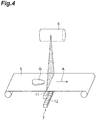
FIG. 4 is a perspective view illustrating inside of a housing of the X-ray inspection apparatus inFIG. 1 ; and -
FIG. 5 is a sectional view illustrating ventilation channels disposed so as to face an X-ray detector depicted inFIG. 4 . - A preferred embodiment of one aspect of the present disclosure will now be described in detail with reference to the attached drawings. In the description of the drawings, like or equivalent elements are designated by like numerals, and duplicate description is omitted. In
FIG. 1 ,FIG. 2 , andFIG. 5 , the directions of "up", "down", "left", "right", "front", and "rear" are defined for convenience of description. However, the embodiment is not limited to these directions. - As depicted in
FIG. 1 to FIG. 4 , anX-ray inspection apparatus 1 includes ahousing 2,support legs 3, aconveyance unit 5, anX-ray emitter 6, anX-ray detector 7, a display-operation unit 8, and acontroller 10. TheX-ray inspection apparatus 1 generates an X-ray transmission image of an article G while conveying the article G, and performs inspection (e.g., examination of the number of accommodated articles, foreign-matter contamination check, missing part check, chipping and cracking check) of the article G on the basis of the X-ray transmission image. An article G before the inspection is carried into theX-ray inspection apparatus 1 by a carry-in conveyor (not depicted). An article G after the inspection is carried out from theX-ray inspection apparatus 1 by a carry-out conveyor (not depicted). An article G that has been determined to be a defective product by theX-ray inspection apparatus 1 is sorted outside a production line by a sorting device (not depicted) disposed downstream of the carry-out conveyor. An article G that has been determined to be a conforming product by theX-ray inspection apparatus 1 passes through the sorting device without being processed. - The
housing 2 accommodates theconveyance unit 5, theX-ray emitter 6, theX-ray detector 7, and thecontroller 10. Thehousing 2 is formed of stainless steel that blocks X-rays, and prevents X-rays from leaking outside. Inside thehousing 2, an inspection area R where an article G is inspected with an X-ray is provided. In thehousing 2, a carry-inport 4a through which an article G is conveyed into the inspection area R and a carry-outport 4b through which the article G is carried out from the inspection area R are formed. An article G before the inspection is carried from the carry-in conveyor into the inspection area R through the carry-inport 4a. An article G after the inspection is carried out from the inspection area R to the carry-out conveyor through the carry-outport 4b. The carry-inport 4a and the carry-outport 4b are each provided with anX-ray blocking curtain 4c for preventing X-rays from leaking. - The
support legs 3 support thehousing 2. Theconveyance unit 5 conveys an article G along a conveying direction A from the carry-inport 4a to the carry-outport 4b via the inspection area R. Theconveyance unit 5 is, for example, a belt conveyor that runs between the carry-inport 4a and the carry-out port 4b. - The
X-ray emitter 6 emits an X-ray onto the article G conveyed by theconveyance unit 5. TheX-ray emitter 6 includes an X-ray tube (not depicted) configured to emit the X-ray, anaccommodation unit 6a in which the X-ray tube is immersed in insulating cooling oil, and acollimator 6b disposed below theaccommodation unit 6a and configured to widen the X-ray emitted from the X-ray tube in a fan shape in a plane perpendicular to the conveying direction A. On outer peripheral surfaces of theaccommodation unit 6a, cooling fins (not depicted) vertically extending are formed. On an upper surface of theaccommodation unit 6a, afan 6c configured to form an air passage upward from below theaccommodation unit 6a is provided. - The
X-ray detector 7 includes afirst line sensor 11 and asecond line sensor 12. Thefirst line sensor 11 and thesecond line sensor 12 each include X-ray detecting elements that are arranged linearly along a horizontal direction perpendicular to the conveying direction A. Thefirst line sensor 11 detects an X-ray, in a low-energy band, that has been transmitted through an article G and a conveyance belt of theconveyance unit 5. Thesecond line sensor 12 detects an X-ray, in a high-energy band, that has been transmitted through the article G, the conveyance belt of theconveyance unit 5, and thefirst line sensor 11. - The
X-ray detector 7 includes thefirst line sensor 11 and thesecond line sensor 12. In the present embodiment, the X-ray detector is configured as anX-ray detection unit 70 in which acontrol board 14 is added to thefirst line sensor 11 and thesecond line sensor 12. TheX-ray detection unit 70 is accommodated in anaccommodation unit 9. Theaccommodation unit 9 is a housing that covers theX-ray detector 7 from the upper, lower, front, rear, right, and left directions. In an upper surface of theaccommodation unit 9, a slit through which an X-ray emitted from theX-ray emitter 6 passes is formed. - As depicted in
FIG. 5 , theaccommodation unit 9 includes a first flow passage (ventilation channel) 61, a second flow passage (ventilation channel) 62, and adisposition portion 63. Thefirst flow passage 61 is disposed so as to face atleast part 70a of theX-ray detection unit 70, and extends from oneend 61a thereof to theother end 61b thereof. In the present embodiment, the oneend 61a and theother end 61b are open toward adoor 2a (seeFIG. 2 ) that is closed. Thefirst flow passage 61 is formed in a U-shape in plan view when viewed from the vertical direction. Similarly to thefirst flow passage 61, thesecond flow passage 62 is disposed so as to face atleast part 70a of theX-ray detection unit 70, and extends from oneend 62a thereof to theother end 62b thereof. In the present embodiment, the oneend 62a and theother end 62b are open toward thedoor 2a that is closed. Thesecond flow passage 62 is formed in a U-shape in plan view when viewed from the vertical direction. Thedisposition portion 63 is a portion on which theX-ray detection unit 70 is disposed. - At the
other end 61b of thefirst flow passage 61 and theother end 62b of thesecond flow passage 62, abracket 65 supportingdischarge fans other end 61b of thefirst flow passage 61 and theother end 62b of thesecond flow passage 62 are connected to thebracket 65 with a gasket (seal member) 67 interposed therebetween. Alternatively, theother end 61b of thefirst flow passage 61 and theother end 62b of thesecond flow passage 62 may be connected to thebracket 65 by welding, for example. Thebracket 65 is formed such that asurface 65a thereof to which thedischarge fans other end 61b of thefirst flow passage 61 and theother end 62b of thesecond flow passage 62 are open so as to be orthogonal to the obliquely rearward and upward direction. When viewed from thedischarge fans air inlets 42 of a cold-air blower 40 are positioned. - As depicted in
FIG. 2 , the display-operation unit 8 is provided to thehousing 2. The display-operation unit 8 displays various types of information and receives inputs for various conditions. The display-operation unit 8 is a liquid crystal display, for example, and displays an operation screen as a touch panel. In this case, an operator can input various conditions with the display-operation unit 8. - As depicted in
FIG. 2 andFIG. 3 , thecontroller 10 is disposed inside thehousing 2. Thecontroller 10 controls operation of each component of theX-ray inspection apparatus 1. Thecontroller 10 includes a central processing unit (CPU), a read only memory (ROM), and a random access memory (RAM). To thecontroller 10, a detection result of an X-ray in the low-energy band is input from the first line sensor 11 (seeFIG. 4 ) of theX-ray detector 7, and also a detection result of an X-ray in the high-energy band is input from the second line sensor 12 (seeFIG. 4 ) of theX-ray detector 7. Based on the detection result of the X-ray in the low-energy band and the detection result of the X-ray in the high-energy band, thecontroller 10 functions as a processing unit configured to determine whether foreign matter is contained in the article G. - As depicted in
FIG. 1 to FIG. 3 , on a rear side of theX-ray inspection apparatus 1, the cold-air blower 40 is disposed. The cold-air blower 40 draws air inside thehousing 2 and outside thehousing 2 from theair inlets 42, exchanges heat of the drawn air with a heat exchanger (not depicted), and supplies the air (cold air) cooled by this heat exchange from asupply port 41 into thehousing 2 through a duct (ventilation channel) 50. In the present embodiment, the cold-air blower 40 is attached to thedoor 2a with which thehousing 2 can be opened and closed. Thedoor 2a is provided with abracket 44 supporting a lower end of the cold-air blower 40. - The
duct 50 includes: afirst duct 51 extending in a front-and-rear direction when thedoor 2a is closed; and twobranch ducts first duct 51 branches off via a branchingportion 54 and that vertically extend. Thefirst duct 51 has openings on oneend 51a thereof and theother end 51b thereof, and between the oneend 51a and theother end 51b, the branchingportion 54 branching into thebranch duct 52 and thebranch duct 53 is provided. The oneend 51a of thefirst duct 51 is connected to thesupply port 41. Theother end 51b of thefirst duct 51 is open forward when thedoor 2a is closed. In other words, when thedoor 2a is closed, theother end 51b is open toward a space in which thecollimator 6b is disposed below theaccommodation unit 6a. - The
branch duct 52 has openings on oneend 52a thereof and theother end 52b thereof. The oneend 52a of thebranch duct 52 is connected to the branchingportion 54. Theother end 52b of thebranch duct 52 is positioned so as to face and be close to the oneend 61a of thefirst flow passage 61 when thedoor 2a is closed (seeFIG. 5 ). Thebranch duct 53 has openings on oneend 53a thereof and theother end 53b thereof. The oneend 53a of thebranch duct 53 is connected to the branchingportion 54. Theother end 53b of thebranch duct 53 is positioned so as to face and be close to the oneend 62a of thesecond flow passage 62 when thedoor 2a is closed (seeFIG. 5 ). - The following describes flows of cold air supplied by the cold-
air blower 40. In the present embodiment, an air-guiding unit configured to guide air to at least part of theX-ray detector 7 includes the cold-air blower 40, thefirst flow passage 61, thesecond flow passage 62, and thedischarge fans 66 described above. As depicted inFIG. 2 andFIG. 3 , cold air supplied by the cold-air blower 40 is supplied from thesupply port 41 of the cold-air blower 40 into thefirst duct 51. The cold air supplied to thefirst duct 51 flows through the branchingportion 54 into thebranch duct 52 and thebranch duct 53. The cold air flowing into thebranch duct 52 is discharged from theother end 52b of thebranch duct 52. The cold air flowing into thebranch duct 53 is discharged from theother end 53b of thebranch duct 53. - As depicted in
FIG. 5 , when thedoor 2a is closed, the cold air discharged from theother end 52b of thebranch duct 52 flows into thefirst flow passage 61 from the oneend 61a of thefirst flow passage 61. The cold air flowing into thefirst flow passage 61 flows forward from the rear side of theaccommodation unit 9, and then flows rearward from the front side thereof as indicated by arrows inFIG. 5 . The cold air flowing through thefirst flow passage 61 facing part of theX-ray detection unit 70 takes heat away from theX-ray detection unit 70. The air the temperature of which has increased (warm air) is discharged from theother end 61b of thefirst flow passage 61 by the correspondingdischarge fan 66. The warm air discharged from thedischarge fan 66 is discharged toward theair inlets 42 of the cold-air blower 40 as depicted inFIG. 2 . Thus, the warm air is drawn from theair inlets 42 of the cold-air blower 40, and is then supplied as cold air again from thesupply port 41. - As depicted in
FIG. 5 , the cold air discharged from theother end 53b of thebranch duct 53 flows into thesecond flow passage 62 from the oneend 62a of thesecond flow passage 62. The cold air flowing into thesecond flow passage 62 flows forward from the rear side of theaccommodation unit 9, and then flows rearward from the front side thereof as indicated by arrows inFIG. 5 . The cold air flowing through thesecond flow passage 62 facing part of theX-ray detection unit 70 takes heat away from theX-ray detection unit 70. The air the temperature of which has increased (warm air) is discharged from theother end 62b of thesecond flow passage 62 by the correspondingdischarge fan 66. The warm air discharged from thedischarge fan 66 is discharged toward theair inlets 42 of the cold-air blower 40 as depicted inFIG. 2 . Thus, the warm air is drawn from theair inlets 42 of the cold-air blower 40, and is then supplied as cold air again from thesupply port 41. - As indicated by arrows in
FIG. 2 , the cold air discharged from theother end 51b of thefirst duct 51 is discharged toward the space in which thecollimator 6b is disposed below theaccommodation unit 6a. The cold air discharged toward the space in which thecollimator 6b is disposed is guided (the flow is guided) upward by thefan 6c. At this time, the air is guided along the cooling fins formed on the outer peripheral surfaces of theaccommodation unit 6a, whereby heat is taken away from the cooling fins. The air the temperature of which has increased is guided toward theair inlets 42 of the cold-air blower 40 by thefan 6c. Thus, the air is drawn from theair inlets 42 of the cold-air blower 40, and is then supplied as cold air again from thesupply port 41. - In the
X-ray inspection apparatus 1 of the embodiment, as depicted inFIG. 5 , by air guided through thefirst flow passage 61 and thesecond flow passage 62, thefirst line sensor 11 and thesecond line sensor 12 can be cooled. Thus, temperature change in thefirst line sensor 11 and thesecond line sensor 12 can be suppressed. - In the
X-ray inspection apparatus 1 of the embodiment, as depicted inFIG. 5 , because theX-ray detection unit 70 faces the first flow passage 61 (second flow passage 62) extending from the oneend 61a (oneend 62a) to theother end 61b (theother end 62b), heat (warm air) generated in theX-ray detection unit 70 can be guided outside theaccommodation unit 9, or cold air can be guided from the outside of theaccommodation unit 9 into theX-ray detection unit 70. Consequently, temperature change in theX-ray detection unit 70 can be suppressed. - In the
X-ray inspection apparatus 1 of the embodiment, theX-ray detection unit 70 includes sensors (thefirst line sensor 11 and the second line sensor 12) configured to detect correspond to X-rays in a plurality of energy bands. In theX-ray inspection apparatus 1 thus configured, for example, a transmission image that can be acquired with an X-ray in a relatively high energy band and a transmission image that can be acquired with an X-ray in a relatively low energy band can be obtained simultaneously. Thus, accuracy in detecting foreign matter, for example, can be increased. Furthermore, even if the X-ray inspection apparatus includes sensors configured to detect X-rays in a plurality of energy bands in which these sensors generate a larger amount of heat than common sensors do, temperature change in theX-ray detection unit 70 can be suppressed. - In the
X-ray inspection apparatus 1 of the embodiment, at theother end 61b of thefirst flow passage 61 and theother end 62b of thesecond flow passage 62, thedischarge fans X-ray detection unit 70 can be guided outside theaccommodation unit 9, or cold air can be guided from the outside of theaccommodation unit 9 into theX-ray detection unit 70. - In the
X-ray inspection apparatus 1 of the embodiment, the other ends 61b and 62b of thefirst flow passage 61 and thesecond flow passage 62 and thebracket 65 on which thedischarge fans gasket 67 interposed therebetween. Thus, airtightness of thefirst flow passage 61 and thesecond flow passage 62 is enhanced, whereby, more effectively, heat generated in theX-ray detection unit 70 can be guided outside theaccommodation unit 9, or cold air can be guided from the outside of theaccommodation unit 9 into theX-ray detection unit 70. - In the
X-ray inspection apparatus 1 of the embodiment, theX-ray detector 7 is configured as theX-ray detection unit 70 including thefirst line sensor 11 and thesecond line sensor 12 together with thecontrol board 14, and thefirst flow passage 61 and thesecond flow passage 62 are disposed so as to face at least theparts X-ray detection unit 70. In theX-ray inspection apparatus 1 thus configured, even when thecontrol board 14 in which a larger amount of heat is generated is formed integrally with thefirst line sensor 11 and thesecond line sensor 12, temperature change in thefirst line sensor 11 and thesecond line sensor 12 can be suppressed. - The
X-ray inspection apparatus 1 of the embodiment includes the cold-air blower 40 configured to supply cold air to thefirst flow passage 61 and thesecond flow passage 62, and thus the temperature of theX-ray detection unit 70 can be prevented from increasing. - In the
X-ray inspection apparatus 1 of the embodiment, theduct 50 for supplying cold air to theX-ray detection unit 70 includes the branching portion 45 such that the cold air is guided also to theX-ray emitter 6. In theX-ray inspection apparatus 1 thus configured, the temperature of theX-ray emitter 6 can be prevented from increasing. - In the
X-ray inspection apparatus 1 of the embodiment, thedischarge fans 66 disposed at theother end 61b of thefirst flow passage 61 and theother end 62b of thesecond flow passage 62 are open toward theair inlets 42 from which air is drawn in the cold-air blower 40. In theX-ray inspection apparatus 1 thus configured, between the cold-air blower 40 and each of thefirst flow passage 61 and thesecond flow passage 62, theX-ray detection unit 70 can be effectively cooled. - In the foregoing, one embodiment has been described. However, one aspect of the present disclosure is not limited to the embodiment, and various modifications can be made without departing from the gist of the present disclosure.
- In the embodiment, an example of what is called a dual energy sensor has been described in which the
first line sensor 11 and thesecond line sensor 12 are included as theX-ray detector 7. However, anX-ray detector 7 including one line sensor may be used instead. - In the embodiment and the modification above, an example has been described in which the
X-ray detector 7 is configured as theX-ray detection unit 70 that is integrally formed including thecontrol board 14. However, sensors such as thefirst line sensor 11 and thesecond line sensor 12 and thecontrol board 14 may be disposed at positions different from each other. In this case, a configuration for cooling the sensors such as thefirst line sensor 11 and thesecond line sensor 12 is indispensable, and cooling also thecontrol board 14 is preferable. - In the embodiment and the modifications above, an example has been described in which the
discharge fans other end 61b of thefirst flow passage 61 and theother end 62b of thesecond flow passage 62. However, instead of or in addition to this configuration, intake fans may be disposed at the oneend 61a of thefirst flow passage 61 and the oneend 62a of thesecond flow passage 62. - In the embodiment and the modifications above, an example has been described in which the
discharge fans other end 61b of thefirst flow passage 61 and theother end 62b of thesecond flow passage 62 discharge warm air toward the cold-air blower 40. However, the discharge fans may be configured to discharge the warm air outside thehousing 2. - In the embodiment and the modifications above, an example has been described in which cold air supplied by the single cold-
air blower 40 is guided to both theX-ray emitter 6 and theX-ray detection unit 70. However, without providing the branching portion 45, for example, the cold-air blower 40 may be used in a dedicated manner for theX-ray detection unit 70. In this case, the branching portion 45, for example, does not have to be provided, and the cold-air blower 40 may supply cold air to theX-ray detection unit 70 through a duct, or may supply the cold air directly to thefirst flow passage 61 and thesecond flow passage 62. - In the embodiment and the modifications above, an example has been described in which the cold-
air blower 40 is provided to thedoor 2a with which the inside of thehousing 2 can be opened or closed. However, the cold-air blower may be disposed inside thehousing 2. Alternatively, from the cold-air blower 40 disposed outside thehousing 2, cold air may be supplied to thefirst flow passage 61 and thesecond flow passage 62 through a duct, for example. - In the embodiment and the modifications above, an example has been described in which the X-ray inspection apparatus includes the cold-
air blower 40 to supply cold air to thefirst flow passage 61 and thesecond flow passage 62 that face theX-ray detector 7. However, the X-ray inspection apparatus may include a heater, for example, instead of the cold-air blower 40, to supply warm air to thefirst flow passage 61 and thesecond flow passage 62. In this case, even when the X-ray inspection apparatus is used in a place such as outdoors where the temperature is low, cold air near theX-ray detector 7 can be guided to outside, or warm air (heat) can be guided from outside to theX-ray detector 7. Consequently, temperature change in theX-ray detector 7 can be suppressed. - In the embodiment and the modifications above, an example has been described in which the X-ray inspection apparatus includes the cold-
air blower 40 or the heater, for example, to supply cold air or warm air to thefirst flow passage 61 and thesecond flow passage 62. However, the X-ray inspection apparatus does not necessarily have to include the cold-air blower 40 and the heater, for example. If thefirst flow passage 61 and thesecond flow passage 62 are provided so as to face part of theX-ray detector 7, air circulates by natural convection, whereby temperature change in theX-ray detector 7 can be suppressed. - In the embodiment and the modifications above, an example has been described in which the
first flow passage 61 and thesecond flow passage 62 are provided. However, without providing thefirst flow passage 61 and thesecond flow passage 62, the X-ray inspection apparatus may include only at least one of the cold-air blower 40 and a fan. Even in this case, wind is guided to thefirst line sensor 11 and thesecond line sensor 12 or theX-ray detection unit 70. - In the embodiment and the modifications above, an example has been described in which the
first flow passage 61 and thesecond flow passage 62 are formed as depicted inFIG. 5 . However, if a flow passage (ventilation channel) facing part of theX-ray detector 7 is used, the shape, arrangement, and wind directions thereof, for example, are not limited to particular ones.
Claims (7)
- An X-ray inspection apparatus comprising:an X-ray emitter configured to emit an X-ray;an X-ray detector configured to detect the X-ray; andan air-guiding unit configured to guide air to at least part of the X-ray detector.
- The X-ray inspection apparatus according to claim 1, wherein the X-ray detector has a plurality of sensors provided to correspond to a plurality of energy bands.
- The X-ray inspection apparatus according to claim 1 or 2, wherein
the X-ray detector is formed integrally as a unit with a control board configured to control the X-ray detector, and
the air-guiding unit is configured to guide air to at least part of the unit. - The X-ray inspection apparatus according to any one of claims 1 to 3, wherein
the air-guiding unit includes:a ventilation channel serving as a flow passage for the air; andat least one of a fan configured to draw the air into the ventilation channel and a fan configured to discharge the air from the ventilation channel. - The X-ray inspection apparatus according to claim 4, wherein the ventilation channel and the at least one of the fans are connected to each other with a seal member interposed therebetween.
- The X-ray inspection apparatus according to claim 4 or 5, further including a cold-air blower configured to supply cold air to the ventilation channel, wherein
the ventilation channel has a branching portion, and
the air-guiding unit is configured such that cold air supplied by the cold-air blower is guided to the X-ray detector and the X-ray emitter through the branching portion. - The X-ray inspection apparatus according to claim 6, wherein one end of the ventilation channel from which air is discharged is open toward an air inlet from which air is drawn in the cold-air blower.
Applications Claiming Priority (1)
| Application Number | Priority Date | Filing Date | Title |
|---|---|---|---|
| JP2018053046A JP2019164088A (en) | 2018-03-20 | 2018-03-20 | X-ray inspection device |
Publications (3)
| Publication Number | Publication Date |
|---|---|
| EP3543746A1 true EP3543746A1 (en) | 2019-09-25 |
| EP3543746B1 EP3543746B1 (en) | 2025-01-22 |
| EP3543746C0 EP3543746C0 (en) | 2025-01-22 |
Family
ID=66091854
Family Applications (1)
| Application Number | Title | Priority Date | Filing Date |
|---|---|---|---|
| EP19163883.2A Active EP3543746B1 (en) | 2018-03-20 | 2019-03-19 | X-ray inspection apparatus |
Country Status (5)
| Country | Link |
|---|---|
| US (1) | US10830711B2 (en) |
| EP (1) | EP3543746B1 (en) |
| JP (3) | JP2019164088A (en) |
| KR (1) | KR102184509B1 (en) |
| CN (1) | CN110308162A (en) |
Families Citing this family (15)
| Publication number | Priority date | Publication date | Assignee | Title |
|---|---|---|---|---|
| CA3071117A1 (en) | 2017-07-31 | 2019-02-07 | Monsanto Technology Llc | Seed sorting |
| EP3764766A4 (en) | 2018-03-14 | 2022-02-23 | Monsanto Technology LLC | SEED IMAGING |
| JP2019164088A (en) * | 2018-03-20 | 2019-09-26 | 株式会社イシダ | X-ray inspection device |
| MX2020013129A (en) | 2018-06-11 | 2021-02-18 | Monsanto Technology Llc | Seed sorting. |
| AU2020383497A1 (en) * | 2019-11-13 | 2022-05-26 | Monsanto Technology Llc | X-ray seed imaging system, cabinet x-ray device, and methods of evaluating seeds |
| KR102153884B1 (en) * | 2020-04-01 | 2020-09-09 | 디케이메디칼시스템(주) | Portable inspection booth, portable x-ray inspection system and method of x-ray inspection using the same |
| JP7634414B2 (en) * | 2021-04-16 | 2025-02-21 | アンリツ株式会社 | X-ray inspection equipment |
| JP7519955B2 (en) * | 2021-05-21 | 2024-07-22 | アンリツ株式会社 | X-ray inspection equipment |
| US12295767B2 (en) * | 2021-08-11 | 2025-05-13 | Shanghai United Imaging Healthcare Co., Ltd. | Detection apparatus and imaging apparatus |
| JP7611119B2 (en) * | 2021-11-09 | 2025-01-09 | アンリツ株式会社 | X-ray inspection equipment |
| JP7846886B2 (en) * | 2022-03-08 | 2026-04-16 | 株式会社イシダ | X-ray inspection equipment and item processing system |
| US11786199B1 (en) * | 2022-03-23 | 2023-10-17 | Seethru AI Inc. | X-ray pencil beam forming system and method |
| WO2024041263A1 (en) * | 2022-08-23 | 2024-02-29 | 上海微现检测设备有限公司 | Method and apparatus for detecting foreign objects in bulk material, and x-ray machine foreign object detection equipment |
| JP2024095280A (en) | 2022-12-28 | 2024-07-10 | 株式会社イシダ | X-ray inspection equipment |
| JP2024122361A (en) | 2023-02-28 | 2024-09-09 | 株式会社イシダ | X-ray inspection equipment |
Citations (5)
| Publication number | Priority date | Publication date | Assignee | Title |
|---|---|---|---|---|
| JP2001318062A (en) | 2000-05-08 | 2001-11-16 | Anritsu Corp | X-ray foreign matter detection device |
| JP2002006049A (en) * | 2000-06-26 | 2002-01-09 | Canon Inc | X-ray digital imaging device |
| US20040202287A1 (en) * | 2003-03-19 | 2004-10-14 | Hans-Jurgen Muller | Cooling system and method to cool a gantry |
| US20070284535A1 (en) * | 2006-05-29 | 2007-12-13 | Bjorn Heismann | Device and method for cooling an X-radiation detector |
| JP2015192803A (en) * | 2014-03-31 | 2015-11-05 | 株式会社東芝 | X-ray computed tomography device |
Family Cites Families (24)
| Publication number | Priority date | Publication date | Assignee | Title |
|---|---|---|---|---|
| US6491428B1 (en) * | 1999-08-30 | 2002-12-10 | Kabushiki Kaisha Toshiba | X-ray computed tomography apparatus |
| DE10058818A1 (en) * | 2000-11-27 | 2002-06-06 | Philips Corp Intellectual Pty | X-ray detector cooler has flow through detector and source |
| DE10304661B4 (en) * | 2003-02-05 | 2007-03-01 | Siemens Ag | Cooling system and method for cooling a gantry |
| JP2006078258A (en) * | 2004-09-08 | 2006-03-23 | Ishida Co Ltd | X-ray inspection system |
| WO2006137919A2 (en) * | 2004-10-29 | 2006-12-28 | Ainsworth, Teresa | Contaminant detector for food inspection |
| US7261466B2 (en) * | 2005-06-01 | 2007-08-28 | Endicott Interconnect Technologies, Inc. | Imaging inspection apparatus with directional cooling |
| DE102006025764B4 (en) * | 2006-05-31 | 2008-07-31 | Siemens Ag | X-ray detector |
| US7916836B2 (en) * | 2007-09-26 | 2011-03-29 | General Electric Company | Method and apparatus for flexibly binning energy discriminating data |
| JP2009222578A (en) * | 2008-03-17 | 2009-10-01 | Toshiba Corp | Solid-state x-ray detector, method of solid-state x-ray detection, and x-ray ct device |
| JP5348940B2 (en) * | 2008-05-09 | 2013-11-20 | 株式会社東芝 | X-ray computed tomography system |
| JP5313843B2 (en) * | 2009-11-06 | 2013-10-09 | 日立アロカメディカル株式会社 | Biological information detection system and method |
| US8532250B2 (en) * | 2010-02-24 | 2013-09-10 | Kabushiki Kaisha Toshiba | X-ray CT apparatus and control method for X-ray CT apparatus |
| JP2011243682A (en) * | 2010-05-17 | 2011-12-01 | Yokogawa Electric Corp | Heat dissipation mechanism |
| JP2012078254A (en) * | 2010-10-04 | 2012-04-19 | Ishida Co Ltd | X-ray inspection device |
| US20130129104A1 (en) * | 2011-11-17 | 2013-05-23 | Ashutosh Joshi | System and method for acoustic noise mitigation in a computed tomography scanner |
| JP2013142783A (en) * | 2012-01-11 | 2013-07-22 | Canon Inc | Projection type display device |
| CN104620098B (en) * | 2012-09-12 | 2019-12-13 | 世高株式会社 | X-ray inspection device |
| JP5672358B2 (en) * | 2013-11-20 | 2015-02-18 | 株式会社リコー | Image forming apparatus |
| JP5632547B2 (en) * | 2014-01-06 | 2014-11-26 | 株式会社東芝 | X-ray CT system |
| JP6654393B2 (en) * | 2015-10-01 | 2020-02-26 | 株式会社イシダ | Foreign matter inspection device |
| JP6619607B2 (en) * | 2015-10-09 | 2019-12-11 | 株式会社イシダ | X-ray inspection equipment |
| US10292251B2 (en) * | 2015-12-14 | 2019-05-14 | Anritsu Infivis Co., Ltd. | X-ray inspection device |
| JP6321227B2 (en) * | 2017-01-17 | 2018-05-09 | キヤノンメディカルシステムズ株式会社 | X-ray computed tomography system |
| JP2019164088A (en) * | 2018-03-20 | 2019-09-26 | 株式会社イシダ | X-ray inspection device |
-
2018
- 2018-03-20 JP JP2018053046A patent/JP2019164088A/en active Pending
-
2019
- 2019-03-18 US US16/356,903 patent/US10830711B2/en active Active
- 2019-03-18 CN CN201910207770.6A patent/CN110308162A/en active Pending
- 2019-03-18 KR KR1020190030473A patent/KR102184509B1/en active Active
- 2019-03-19 EP EP19163883.2A patent/EP3543746B1/en active Active
-
2023
- 2023-08-14 JP JP2023131854A patent/JP7808339B2/en active Active
-
2025
- 2025-09-25 JP JP2025158764A patent/JP2025175165A/en active Pending
Patent Citations (5)
| Publication number | Priority date | Publication date | Assignee | Title |
|---|---|---|---|---|
| JP2001318062A (en) | 2000-05-08 | 2001-11-16 | Anritsu Corp | X-ray foreign matter detection device |
| JP2002006049A (en) * | 2000-06-26 | 2002-01-09 | Canon Inc | X-ray digital imaging device |
| US20040202287A1 (en) * | 2003-03-19 | 2004-10-14 | Hans-Jurgen Muller | Cooling system and method to cool a gantry |
| US20070284535A1 (en) * | 2006-05-29 | 2007-12-13 | Bjorn Heismann | Device and method for cooling an X-radiation detector |
| JP2015192803A (en) * | 2014-03-31 | 2015-11-05 | 株式会社東芝 | X-ray computed tomography device |
Also Published As
| Publication number | Publication date |
|---|---|
| JP7808339B2 (en) | 2026-01-29 |
| CN110308162A (en) | 2019-10-08 |
| JP2023153248A (en) | 2023-10-17 |
| US10830711B2 (en) | 2020-11-10 |
| KR20190110450A (en) | 2019-09-30 |
| EP3543746B1 (en) | 2025-01-22 |
| JP2019164088A (en) | 2019-09-26 |
| US20190297717A1 (en) | 2019-09-26 |
| JP2025175165A (en) | 2025-11-28 |
| EP3543746C0 (en) | 2025-01-22 |
| KR102184509B1 (en) | 2020-11-30 |
Similar Documents
| Publication | Publication Date | Title |
|---|---|---|
| EP3543746B1 (en) | X-ray inspection apparatus | |
| US12467885B2 (en) | X-ray inspection device | |
| JP2019164088A5 (en) | ||
| US20160033162A1 (en) | Indoor unit for air-conditioning apparatus | |
| KR20160109918A (en) | Display apparatus | |
| US7201515B2 (en) | System and method for cooling components rotatable about an axis | |
| US20240288592A1 (en) | X-ray inspection apparatus | |
| JP4965889B2 (en) | X-ray inspection equipment | |
| CN104939856A (en) | CT system | |
| JP2012078254A (en) | X-ray inspection device | |
| US10292251B2 (en) | X-ray inspection device | |
| JP6830243B2 (en) | X-ray inspection equipment | |
| JP2013088199A (en) | X-ray inspection apparatus | |
| JP6619607B2 (en) | X-ray inspection equipment | |
| US11940393B2 (en) | X-ray inspection apparatus | |
| CN115279645B (en) | Vehicles used to transport people | |
| JP2023070492A (en) | X-ray inspection device | |
| JP3172652U (en) | X-ray inspection equipment | |
| JP2012078257A (en) | X-ray inspection device | |
| JP2009085543A (en) | Showcase and delivery system | |
| JP7500487B2 (en) | X-ray inspection equipment | |
| JP2012078255A (en) | X-ray inspection device | |
| TW202533882A (en) | Gas cabinet with reduced gas emissions and exhaust flow rate | |
| CN106662359A (en) | Indoor unit for air conditioning device | |
| JP2023086228A (en) | X-ray inspection device |
Legal Events
| Date | Code | Title | Description |
|---|---|---|---|
| PUAI | Public reference made under article 153(3) epc to a published international application that has entered the european phase |
Free format text: ORIGINAL CODE: 0009012 |
|
| STAA | Information on the status of an ep patent application or granted ep patent |
Free format text: STATUS: REQUEST FOR EXAMINATION WAS MADE |
|
| 17P | Request for examination filed |
Effective date: 20190319 |
|
| AK | Designated contracting states |
Kind code of ref document: A1 Designated state(s): AL AT BE BG CH CY CZ DE DK EE ES FI FR GB GR HR HU IE IS IT LI LT LU LV MC MK MT NL NO PL PT RO RS SE SI SK SM TR |
|
| AX | Request for extension of the european patent |
Extension state: BA ME |
|
| STAA | Information on the status of an ep patent application or granted ep patent |
Free format text: STATUS: EXAMINATION IS IN PROGRESS |
|
| 17Q | First examination report despatched |
Effective date: 20220322 |
|
| REG | Reference to a national code |
Ref country code: DE Ref legal event code: R079 Free format text: PREVIOUS MAIN CLASS: G01T0007000000 Ipc: G01V0005000000 Ref document number: 602019065019 Country of ref document: DE |
|
| GRAP | Despatch of communication of intention to grant a patent |
Free format text: ORIGINAL CODE: EPIDOSNIGR1 |
|
| STAA | Information on the status of an ep patent application or granted ep patent |
Free format text: STATUS: GRANT OF PATENT IS INTENDED |
|
| RIC1 | Information provided on ipc code assigned before grant |
Ipc: G01V 5/00 20060101AFI20240828BHEP |
|
| INTG | Intention to grant announced |
Effective date: 20240912 |
|
| RAP3 | Party data changed (applicant data changed or rights of an application transferred) |
Owner name: ISHIDA CO., LTD. |
|
| GRAS | Grant fee paid |
Free format text: ORIGINAL CODE: EPIDOSNIGR3 |
|
| GRAA | (expected) grant |
Free format text: ORIGINAL CODE: 0009210 |
|
| STAA | Information on the status of an ep patent application or granted ep patent |
Free format text: STATUS: THE PATENT HAS BEEN GRANTED |
|
| AK | Designated contracting states |
Kind code of ref document: B1 Designated state(s): AL AT BE BG CH CY CZ DE DK EE ES FI FR GB GR HR HU IE IS IT LI LT LU LV MC MK MT NL NO PL PT RO RS SE SI SK SM TR |
|
| REG | Reference to a national code |
Ref country code: GB Ref legal event code: FG4D |
|
| REG | Reference to a national code |
Ref country code: CH Ref legal event code: EP |
|
| REG | Reference to a national code |
Ref country code: DE Ref legal event code: R096 Ref document number: 602019065019 Country of ref document: DE |
|
| REG | Reference to a national code |
Ref country code: IE Ref legal event code: FG4D |
|
| U01 | Request for unitary effect filed |
Effective date: 20250129 |
|
| U07 | Unitary effect registered |
Designated state(s): AT BE BG DE DK EE FI FR IT LT LU LV MT NL PT RO SE SI Effective date: 20250205 |
|
| U20 | Renewal fee for the european patent with unitary effect paid |
Year of fee payment: 7 Effective date: 20250429 |
|
| PG25 | Lapsed in a contracting state [announced via postgrant information from national office to epo] |
Ref country code: RS Free format text: LAPSE BECAUSE OF FAILURE TO SUBMIT A TRANSLATION OF THE DESCRIPTION OR TO PAY THE FEE WITHIN THE PRESCRIBED TIME-LIMIT Effective date: 20250422 |
|
| PG25 | Lapsed in a contracting state [announced via postgrant information from national office to epo] |
Ref country code: PL Free format text: LAPSE BECAUSE OF FAILURE TO SUBMIT A TRANSLATION OF THE DESCRIPTION OR TO PAY THE FEE WITHIN THE PRESCRIBED TIME-LIMIT Effective date: 20250122 |
|
| PG25 | Lapsed in a contracting state [announced via postgrant information from national office to epo] |
Ref country code: ES Free format text: LAPSE BECAUSE OF FAILURE TO SUBMIT A TRANSLATION OF THE DESCRIPTION OR TO PAY THE FEE WITHIN THE PRESCRIBED TIME-LIMIT Effective date: 20250122 |
|
| PG25 | Lapsed in a contracting state [announced via postgrant information from national office to epo] |
Ref country code: NO Free format text: LAPSE BECAUSE OF FAILURE TO SUBMIT A TRANSLATION OF THE DESCRIPTION OR TO PAY THE FEE WITHIN THE PRESCRIBED TIME-LIMIT Effective date: 20250422 Ref country code: IS Free format text: LAPSE BECAUSE OF FAILURE TO SUBMIT A TRANSLATION OF THE DESCRIPTION OR TO PAY THE FEE WITHIN THE PRESCRIBED TIME-LIMIT Effective date: 20250522 |
|
| PG25 | Lapsed in a contracting state [announced via postgrant information from national office to epo] |
Ref country code: HR Free format text: LAPSE BECAUSE OF FAILURE TO SUBMIT A TRANSLATION OF THE DESCRIPTION OR TO PAY THE FEE WITHIN THE PRESCRIBED TIME-LIMIT Effective date: 20250122 |
|
| PG25 | Lapsed in a contracting state [announced via postgrant information from national office to epo] |
Ref country code: GR Free format text: LAPSE BECAUSE OF FAILURE TO SUBMIT A TRANSLATION OF THE DESCRIPTION OR TO PAY THE FEE WITHIN THE PRESCRIBED TIME-LIMIT Effective date: 20250423 |
|
| PG25 | Lapsed in a contracting state [announced via postgrant information from national office to epo] |
Ref country code: SM Free format text: LAPSE BECAUSE OF FAILURE TO SUBMIT A TRANSLATION OF THE DESCRIPTION OR TO PAY THE FEE WITHIN THE PRESCRIBED TIME-LIMIT Effective date: 20250122 |
|
| PG25 | Lapsed in a contracting state [announced via postgrant information from national office to epo] |
Ref country code: MC Free format text: LAPSE BECAUSE OF FAILURE TO SUBMIT A TRANSLATION OF THE DESCRIPTION OR TO PAY THE FEE WITHIN THE PRESCRIBED TIME-LIMIT Effective date: 20250122 |
|
| PG25 | Lapsed in a contracting state [announced via postgrant information from national office to epo] |
Ref country code: CZ Free format text: LAPSE BECAUSE OF FAILURE TO SUBMIT A TRANSLATION OF THE DESCRIPTION OR TO PAY THE FEE WITHIN THE PRESCRIBED TIME-LIMIT Effective date: 20250122 |
|
| REG | Reference to a national code |
Ref country code: CH Ref legal event code: H13 Free format text: ST27 STATUS EVENT CODE: U-0-0-H10-H13 (AS PROVIDED BY THE NATIONAL OFFICE) Effective date: 20251023 |
|
| PG25 | Lapsed in a contracting state [announced via postgrant information from national office to epo] |
Ref country code: SK Free format text: LAPSE BECAUSE OF FAILURE TO SUBMIT A TRANSLATION OF THE DESCRIPTION OR TO PAY THE FEE WITHIN THE PRESCRIBED TIME-LIMIT Effective date: 20250122 |
|
| PLBE | No opposition filed within time limit |
Free format text: ORIGINAL CODE: 0009261 |
|
| STAA | Information on the status of an ep patent application or granted ep patent |
Free format text: STATUS: NO OPPOSITION FILED WITHIN TIME LIMIT |
|
| 26N | No opposition filed |
Effective date: 20251023 |
|
| PG25 | Lapsed in a contracting state [announced via postgrant information from national office to epo] |
Ref country code: CH Free format text: LAPSE BECAUSE OF NON-PAYMENT OF DUE FEES Effective date: 20250331 |
|
| PG25 | Lapsed in a contracting state [announced via postgrant information from national office to epo] |
Ref country code: IE Free format text: LAPSE BECAUSE OF NON-PAYMENT OF DUE FEES Effective date: 20250319 |
|
| PGFP | Annual fee paid to national office [announced via postgrant information from national office to epo] |
Ref country code: GB Payment date: 20260324 Year of fee payment: 8 |
|
| U20 | Renewal fee for the european patent with unitary effect paid |
Year of fee payment: 8 Effective date: 20260327 |