EP3543600A2 - Mixing rod for mixing a light beam and lighting device with such a mixing rod - Google Patents
Mixing rod for mixing a light beam and lighting device with such a mixing rod Download PDFInfo
- Publication number
- EP3543600A2 EP3543600A2 EP19164262.8A EP19164262A EP3543600A2 EP 3543600 A2 EP3543600 A2 EP 3543600A2 EP 19164262 A EP19164262 A EP 19164262A EP 3543600 A2 EP3543600 A2 EP 3543600A2
- Authority
- EP
- European Patent Office
- Prior art keywords
- light
- mixing rod
- mixing
- exit surface
- lens
- Prior art date
- Legal status (The legal status is an assumption and is not a legal conclusion. Google has not performed a legal analysis and makes no representation as to the accuracy of the status listed.)
- Pending
Links
Images

Classifications
-
- G—PHYSICS
- G02—OPTICS
- G02B—OPTICAL ELEMENTS, SYSTEMS OR APPARATUS
- G02B6/00—Light guides; Structural details of arrangements comprising light guides and other optical elements, e.g. couplings
- G02B6/0001—Light guides; Structural details of arrangements comprising light guides and other optical elements, e.g. couplings specially adapted for lighting devices or systems
- G02B6/0011—Light guides; Structural details of arrangements comprising light guides and other optical elements, e.g. couplings specially adapted for lighting devices or systems the light guides being planar or of plate-like form
- G02B6/0013—Means for improving the coupling-in of light from the light source into the light guide
- G02B6/0015—Means for improving the coupling-in of light from the light source into the light guide provided on the surface of the light guide or in the bulk of it
- G02B6/002—Means for improving the coupling-in of light from the light source into the light guide provided on the surface of the light guide or in the bulk of it by shaping at least a portion of the light guide, e.g. with collimating, focussing or diverging surfaces
-
- G—PHYSICS
- G02—OPTICS
- G02B—OPTICAL ELEMENTS, SYSTEMS OR APPARATUS
- G02B19/00—Condensers, e.g. light collectors or similar non-imaging optics
- G02B19/0004—Condensers, e.g. light collectors or similar non-imaging optics characterised by the optical means employed
- G02B19/0009—Condensers, e.g. light collectors or similar non-imaging optics characterised by the optical means employed having refractive surfaces only
- G02B19/0014—Condensers, e.g. light collectors or similar non-imaging optics characterised by the optical means employed having refractive surfaces only at least one surface having optical power
-
- G—PHYSICS
- G02—OPTICS
- G02B—OPTICAL ELEMENTS, SYSTEMS OR APPARATUS
- G02B19/00—Condensers, e.g. light collectors or similar non-imaging optics
- G02B19/0033—Condensers, e.g. light collectors or similar non-imaging optics characterised by the use
- G02B19/0047—Condensers, e.g. light collectors or similar non-imaging optics characterised by the use for use with a light source
- G02B19/0061—Condensers, e.g. light collectors or similar non-imaging optics characterised by the use for use with a light source the light source comprising a LED
- G02B19/0066—Condensers, e.g. light collectors or similar non-imaging optics characterised by the use for use with a light source the light source comprising a LED in the form of an LED array
-
- G—PHYSICS
- G02—OPTICS
- G02B—OPTICAL ELEMENTS, SYSTEMS OR APPARATUS
- G02B6/00—Light guides; Structural details of arrangements comprising light guides and other optical elements, e.g. couplings
- G02B6/0001—Light guides; Structural details of arrangements comprising light guides and other optical elements, e.g. couplings specially adapted for lighting devices or systems
- G02B6/0005—Light guides; Structural details of arrangements comprising light guides and other optical elements, e.g. couplings specially adapted for lighting devices or systems the light guides being of the fibre type
- G02B6/0008—Light guides; Structural details of arrangements comprising light guides and other optical elements, e.g. couplings specially adapted for lighting devices or systems the light guides being of the fibre type the light being emitted at the end of the fibre
-
- G—PHYSICS
- G02—OPTICS
- G02B—OPTICAL ELEMENTS, SYSTEMS OR APPARATUS
- G02B6/00—Light guides; Structural details of arrangements comprising light guides and other optical elements, e.g. couplings
- G02B6/0001—Light guides; Structural details of arrangements comprising light guides and other optical elements, e.g. couplings specially adapted for lighting devices or systems
- G02B6/0011—Light guides; Structural details of arrangements comprising light guides and other optical elements, e.g. couplings specially adapted for lighting devices or systems the light guides being planar or of plate-like form
- G02B6/0033—Means for improving the coupling-out of light from the light guide
- G02B6/0035—Means for improving the coupling-out of light from the light guide provided on the surface of the light guide or in the bulk of it
- G02B6/0045—Means for improving the coupling-out of light from the light guide provided on the surface of the light guide or in the bulk of it by shaping at least a portion of the light guide
-
- G—PHYSICS
- G02—OPTICS
- G02B—OPTICAL ELEMENTS, SYSTEMS OR APPARATUS
- G02B27/00—Optical systems or apparatus not provided for by any of the groups G02B1/00 - G02B26/00, G02B30/00
- G02B27/09—Beam shaping, e.g. changing the cross-sectional area, not otherwise provided for
- G02B27/0938—Using specific optical elements
- G02B27/0994—Fibers, light pipes
-
- G—PHYSICS
- G02—OPTICS
- G02B—OPTICAL ELEMENTS, SYSTEMS OR APPARATUS
- G02B6/00—Light guides; Structural details of arrangements comprising light guides and other optical elements, e.g. couplings
- G02B6/0001—Light guides; Structural details of arrangements comprising light guides and other optical elements, e.g. couplings specially adapted for lighting devices or systems
- G02B6/0011—Light guides; Structural details of arrangements comprising light guides and other optical elements, e.g. couplings specially adapted for lighting devices or systems the light guides being planar or of plate-like form
- G02B6/0033—Means for improving the coupling-out of light from the light guide
- G02B6/005—Means for improving the coupling-out of light from the light guide provided by one optical element, or plurality thereof, placed on the light output side of the light guide
-
- G—PHYSICS
- G02—OPTICS
- G02B—OPTICAL ELEMENTS, SYSTEMS OR APPARATUS
- G02B6/00—Light guides; Structural details of arrangements comprising light guides and other optical elements, e.g. couplings
- G02B6/0001—Light guides; Structural details of arrangements comprising light guides and other optical elements, e.g. couplings specially adapted for lighting devices or systems
- G02B6/0011—Light guides; Structural details of arrangements comprising light guides and other optical elements, e.g. couplings specially adapted for lighting devices or systems the light guides being planar or of plate-like form
- G02B6/0066—Light guides; Structural details of arrangements comprising light guides and other optical elements, e.g. couplings specially adapted for lighting devices or systems the light guides being planar or of plate-like form characterised by the light source being coupled to the light guide
- G02B6/0073—Light emitting diode [LED]
Definitions
- the present invention relates to a mixing rod for mixing a light beam of an inhomogeneous light source and a lighting device with such a mixing rod.
- Mixing rods for mixing a light beam are for example from US 2007/0024971 A1 known. With these mixing rods, a light beam is to be generated, which is approximately circular in cross section and has a substantially uniform light intensity distribution and a uniform illumination intensity distribution at the light exit, ie a mixing of the light in the direction and location. It is also to be avoided with these light bars, as is known from other light bars, that a multiple image of the light source is produced, thereby causing a light intensity distribution similar to a kaleidoscope. Such kaleidoscopic light intensity distributions are very inhomogeneous and should therefore be avoided.
- the mixing rod should also be designed so that it already causes a good mixing with a short length.
- these known mixing rods have grooved lateral surfaces which are intended to effect a uniform mixing of the light beam.
- the cross-sectional shape of these mixing rods may be circular, elliptical, oval, rectangular or in the form of a pentagon, hexagon or other polygon.
- the mixing rod can be conically shaped between a light entry surface and a light exit surface.
- the light exit surface may be curved to form a lens.
- From the US 2013/0294066 A1 shows a further mixing rod, which has a light entrance surface and a light exit surface, wherein the light rod is adjacent to the light entrance surface of a truncated pyramid and adjacent to the light exit surface conical with a circular cross section.
- the light entry surface and / or the light exit surface may also be curved so as to give the mixing rod a lens function.
- the inner surfaces are formed reflective. By multiple reflection on these surfaces, the light source is mapped multiple times, similar to a kaleidoscope.
- the shape of the light guide is asymmetrical.
- a device for optical coupling between at least one light source and an output device is disclosed.
- the coupling is in this case designed as a light guide, which leads in each case a luminous flux in two parallel strands.
- the strands are separated by a gap.
- the device has a Fresnel lens as an optical input.
- the output system may include one or more lens units.
- a mixing of the light beams is changed by the generation of parallel light beams in the light guide. Even if the lens elements on the output system ensure a certain mixing, the light guide itself is not responsible for the mixing.
- the lighting unit has at least one luminous means, a light-guiding element, a light coupling-in area and a light coupling-out area.
- the visible light of the illuminant can be coupled into the Lichteinkoppel Anlagen.
- the coupled light is reflected at a deflection region and the reflected light is coupled out of the light extraction region.
- a collimating and homogenizing system for an LED lamp includes an LED light source, a light collimation with a receiving lens and an exit lens, both lenses being equipped with overflow protection shields.
- the collimator has a square input cross section and a hexagonal or octagonal output cross section and is conical, so that the input cross section is smaller than the output cross section.
- the optical device comprises a first and a second light-guiding element.
- the two light-guiding elements are formed separately.
- the cross section of the light guide elements can change along the light guide elements.
- a light guide which has an uneven light entrance surface and flat side surfaces which are directly downstream of the light entrance surface. Further, an optoelectronic component is specified with such a light guide.
- the light guide has two sections, the first being widened and the second being configured slightly widening.
- mixing rods which have a rough light exit surface, so that the light is scattered. This is intended to improve the mixing of the light.
- rough scattered surfaces lead to significant light losses.
- lighting devices which have a mixing rod, wherein adjacent to the light exit surface of the mixing rod additionally a lens is provided.
- This lens has at least a rough surface.
- the present invention has for its object to provide a mixing rod for mixing a light beam of an inhomogeneous light source and a lighting device with such a mixing rod, the mixing rod is simple and inexpensive to produce, causes a very good mixing of the light beam in place and direction and still the Light losses are low.
- Another object is to expand or bundle the light beam.
- Another object is to convert the cross section of the light beam in an approximately circular contour.
- a mixing rod according to the invention for mixing a light beam of an inhomogeneous light source is formed from an elongated transparent body having a light entrance surface, a lateral surface and a light exit surface.
- the light exit surface is substantially convex and the light exit surface has several facets.
- Such a faceted light exit surface increases the quality of the mixing of the light beam considerably.
- the individual facets can be planar or curved.
- the facets together form the convex shaped light exit surface.
- the mixing rod is given a lens function.
- This convexly or concavely curved light exit surface has the effect that a virtual image of the light source with a convex shaped light exit surface is moved a bit backwards and concave curvature forward a bit, with the direction from the center of the mixing rod towards the entrance surface and means forward in the direction of the center of the mixing rod to the exit surface.
- a corresponding displacement of the virtual image also takes place with a concave or convex design of the light entry surface.
- the mixing rod thus acts much like a lens.
- the mixing rod can be combined with another lens without the danger that the light source will be accurately imaged by this lens, as moving the virtual image of the light source can ensure that the virtual image is not imaged Focus of the lens is arranged. If the virtual image were to be arranged in the focus of the lens, then the intermixing would be canceled out at least to a considerable extent and multiple images of the light source as well as the structures of the light source would be recognizable in the light intensity distribution of the light beam. This will be explained in more detail below in the description of the lighting device.
- the mixing rod according to the invention thus combines a very good mixing property for mixing the light beam with an excellent efficiency and is inexpensive to produce due to the simple shape.
- the individual facets are smooth or substantially smooth.
- Substantially smooth means that the arithmetic mean roughness Ra is not greater than 1.0 ⁇ m, preferably not greater than 0.4 ⁇ m, and in particular not greater than 0.1 ⁇ m.
- the light exit surface is curved.
- the curved light exit surface or the curved light entry surface is convexly curved.
- the light exit surface preferably has a plurality of facets in the radial and / or circumferential direction.
- the mixing rod may have the shape of a polygon in cross-section at least in the region adjacent to the light exit surface.
- the polygon has more than four corners, in particular more than six corners, preferably more than seven or nine or ten or eleven or twelve or thirteen corners, so that the image plane can not be completely covered.
- a circle, or an ellipse is not a polygon in the sense of the present invention. With a circular or elliptical cross-sectional area, the mixing property is inferior as compared with a polygon cross-sectional area.
- the cross-sectional shape can be the same over the entire length of the mixing rod, wherein the cross-sectional area can vary along the longitudinal extent of the mixing rod.
- the mixing rod is preferably designed to widen conically from the light entry surface to the light exit surface. This leads to a bundling of the light beam.
- the mixing rod according to the invention is designed such that it has at least two sections, a Formüber arrangements- and a Homogenticiansabites.
- the shape transfer section and the homogenization section are arranged one behind the other between the light entrance and the light exit surface.
- Such a mixing bar gives a better result with respect to the homogenization than a uniform widening over the entire mixing length.
- the mixing rod has in the region adjacent to the light exit surface in cross section in the shape of a polygon.
- the polygon has more than four corners.
- edge length of the polygon is not less than the wavelength of the light, it may affect the reflection.
- the number of corners is preferably odd. If light is passed through the mixing rod, the light reflected back almost perpendicularly by an edge of the mixing rod in cross section is then thrown back again at at least two further edges. This increases the mixing again.
- a circle, or an ellipse is not a polygon in the sense of the present invention.
- the mixing property is inferior as compared with a polygon cross-sectional area.
- the length of the homogenization section can be at least 20%, or 40% and preferably at least 50%, in particular at least 65%, and preferably at least 80% of the total length of the mixing rod.
- the homogenization section has a substantially constant cross-sectional area, that is, the size of the cross-sectional area but not necessarily the shape of the cross-sectional area is constant.
- the size of the cross-sectional area may vary slightly without affecting the homogenization.
- the cross-sectional area may be formed slightly widening or tapering in the direction of the light exit surface.
- the shape of the cross-sectional area is constant.
- a better mixing of the light can be achieved, as in a discontinuous or continuous change in the cross-sectional size.
- the cross-sectional shape has more than five corners, in particular more than six corners, preferably seven or nine or ten or eleven or twelve or thirteen corners, so that the image plane can not be completely covered.
- the cross-sectional shape preferably has an odd number of corners. With an even number of corners, there may be symmetries that affect the mixing action of the mixing rod 1.
- the shape transfer section can expand from the light entry surface to an interface with the homogenization section. However, it can also be designed so that the cross-sectional area of the shape transfer section is always approximately the same size.
- the interface is preferably parallel to the light entry surface.
- the etendue is at least approximately obtained, whereby the best possible collimation of the emerging from the mixing rod light beam.
- the shape and size of the cross section of the two sections be the same, whereby the transition is continuous and the two sections are flush with each other.
- the shape of the cross section at the light entrance surface and the shape of the cross section at the interface differ Accordingly, it may be convenient if the shape of the cross section of the shape transfer section changes gradually, for example, from a quadrangle to a corner.
- An Elfeck creates a better color mixing than a square.
- a quadrangle may cover the shape of the light source.
- the corners can be sharp-edged or rounded.
- the lateral surface of the mixing rod is preferably formed of smooth segments, whereby the light losses are kept low.
- the segments of the lateral surfaces can be planar or slightly curved.
- the length of the mixing rod is preferably at least 1 cm, in particular at least 4 cm, or at least 8 cm.
- the ratio of the length to the diameter at the light entry surface is at least 3: 1, in particular at least 10: 1, and preferably at least 15: 1. If the light entry surface is in the form of a polygon, then the diameter of the light entry surface is the largest possible path length within the corresponding polygon. At the square, it is the diagonal.
- a cross-sectional area of the mixing rod is basically perpendicular to the optical axis of the mixing rod.
- An expansion in the sense of the present invention is the enlargement of this diameter and a taper the reduction of this diameter.
- the cross-sectional area increases but the diameters are preserved.
- the shape transfer section should be as short as possible and the widening of the shape transfer section as fast as possible.
- the widening of the shape transfer section should not be too fast, because then the effect achieved by an expansion of the bundling of the light be impaired, since a part of the light entering at larger entrance angles at the light entrance surface is not reflected on the boundary surface of the shape transfer section and thus exits at the exit surface of the mixing rod at a correspondingly large angle. As a result, this light does not reach the desired target area.
- the length of the shape transfer section may be at most 30%, or at most 25% and preferably at most 20%, in particular at most 15%, and preferably at most 10% of the total length of the mixing rod.
- the shape transfer section preferably has a length which is at least 0.8 times the diameter of the entry surface or at least 1.2 times, or at least 1.5 times, or at least 2 times, or at least 2 , 5 times the diameter of the entrance surface corresponds. If the light entry surface is in the form of a polygon, then the diameter of the light entry surface is again the largest possible route length within the corresponding polygon.
- the shape transfer section represents the area in which the shape of the entrance surface is converted to the cross-sectional shape of the homogenization section.
- the mixing rod is preferably formed of a transparent plastic. In principle, it can also be made of glass. However, the preferred material is a silicone-based plastic or PMMA or PMMI. This material is easy to process, has a high transparency, whereby the light losses are kept low and is long-term stable and UV-stable. Silicone-based plastic and PMMI are also insensitive to temperature.
- a lighting device which comprises a light source, a mixing rod and a lens.
- the mixing rod corresponds to one of the above-explained mixing rods and is arranged pointing with its light entry surface in the direction of the light source.
- the lens is preferably displaceable along an optical axis of the corresponding mixing rod and arranged adjacent to the light exit surface.
- the lens is preferably made of a transparent plastic, in particular silicone.
- silicone also has the advantage that the lens can be produced simply and inexpensively.
- a relatively large Anspritz Design is required for ordinary plastic, which may possibly protrude into the optical surfaces.
- thick lenses made of ordinary plastic must be pressed accordingly, which extends the cycle time and thus increases the cost.
- the beam cone, with which the light beam exiting from the illumination device is derived can be adjusted differently.
- the latter With a suitable choice of curvature, generates a virtual image of the light source which is not in the vicinity or within the focus range of the lens, which could be the case with a mixing rod with a planar exit surface.
- a virtual image of the light source, which is located in the vicinity of or within the focus range of the lens, should be avoided as far as possible, since in this way the mixture of the light beam through the mixing rod is at least partially canceled out.
- the distance between the focus of the lens and the virtual image generated by the mixing rod is at least 1 mm, preferably at least 1 cm and in particular at least 5 cm.
- the boundary of the displacement region is designed such that a distance between the focus of the lens and the virtual image generated by the mixing rod remains.
- no further optical element in particular no further optical elements for mixing, is or are arranged along the optical axis in the region between the light source and the lens other than the mixing rod. Due to the configuration of the mixing rod, no further optical elements, such as scattering disks, are necessary in order to obtain a sufficient mixing of the light beam.
- the light source preferably has a plurality of light emitting diodes or a light emitting diode with a plurality of illuminated surfaces.
- the lighting device also makes sense for other inhomogeneous Light sources, characterized by an inhomogeneous specific light emission and / or an inhomogeneous color distribution and / or an inhomogeneous directional distribution.
- the lighting device may have a plurality of mixing rods, which are each assigned at least one light source.
- Each mixing rod may be associated with a separate lens.
- the lenses are moved together or in groups along the optical axis of the individual mixing rods. However, it can also be provided a common lens, which covers the light exit surfaces of all mixing rods
- the illumination device adjacent to the light exit surface of the lens may have a diffusing screen, which preferably has holographic, micro and / or nanostructures.
- a diffusing screen which preferably has holographic, micro and / or nanostructures.
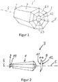
- a mixing rod 1 according to the invention is an elongated, monolithic body made of a transparent material ( Fig. 1 ).
- the mixing rod 1 has a light entry surface 2, a lateral surface 3 and a light exit surface 4.
- An optical axis 5 extends through the center of the light entry surface 2 and the center of the light exit surface 4.
- the light entry surface 2 is planar and perpendicular to the optical axis. 5
- the light exit surface 4 is substantially convexly curved and composed of several smooth facets 6.
- the light exit surface 4 of two annular sets of seven facets 6/1 and 6/2 and a central facet 6/3 is formed.
- the annularly arranged facets 6/1 and 6/2 are each planar facets, wherein the central facet 6/3 has a slight convex curvature.
- the mixing rod 1 has a polygonal cross section, wherein the cross section in the present embodiment is a heptagon (heptagon). Accordingly, the lateral surface 3 is formed of seven planar segments.
- the mixing rod 1 may also be formed with a different cross-sectional shape.
- the polygon preferably has an odd number of vertices.
- the polygons are preferably regular polygons.
- the light entry surface 2 is formed planar. In the context of the invention, it may be expedient that the light entry surface 2 is concave or convex.
- the cross-sectional area is smaller at the light entry surface 2 than at the light exit surface 4, so that the mixing rod widens conically from the light entry surface 2 to the light exit surface 4.
- the light source 8 is a light-emitting diode array with a plurality of light-emitting diodes 10.
- the light-emitting diode array 8 is arranged perpendicular to the optical axis 5 of the mixing rod 1 and with the light emitting diodes 10 pointing in the direction of the light entry surface 2. As a result, the light emitted by the light-emitting diodes 10 enters the mixing rod 1 at the light entry surface 2.
- the distance between the Light emitting diode array 8 and the light entrance surface 2 is as small as possible in order to capture as much as possible of the total amount of light with the mixing rod 1.
- FIG. 2 is the distance between the light-emitting diode array 8 and the light entry surface 2 larger than shown in reality for easier graphical representation.
- the lens 9 is arranged adjacent to the light exit surface 4 of the mixing rod 1.
- the lens 9 is arranged concentrically to the optical axis 5 of the mixing rod and is movable along the optical axis 5.
- suitable guide elements are provided, which are known in the art and for easier graphical representation in FIG. 2 are omitted.
- the lens 9 has a convexly curved surface 11 facing the mixing rod 1 and a convexly curved surface 12 facing away from the mixing rod 1.
- the surface facing the mixing rod 1 surface 11 is planar, concave or otherwise curved.
- the lens 9 is preferably also formed of a plastic material, in particular a plastic material based on silicone.
- the lens 9 can be moved very close to the light exit surface 4. The closer the lens 9 is to the light exit surface 4, the more the expansion of the cone of the light beam is changed by moving the lens. Therefore, it is expedient that there are no further optical elements in the region between the light exit surface 4 and the lens 9, so that the lens 9 can be moved to the light exit surface 4.
- the largest possible adjustable angle range is very advantageous.
- the light exit surface 4 has a dual function, on the one hand by the curvature causes a lens function of the mixing rod 1 and on the other hand promotes the mixing of the light beam by providing the plurality of facets 6.
- the mixing rod 1 preferably has at least four facets, in particular at least ten facets and particularly preferably at least fifteen facets.
- the number of facets at the exit should not be greater than 200 and in particular not greater than 150 or not greater than 100.
- the maximum number of facets may be limited by the manufacturing process. In injection molding, small facets can not be represented and result in a more or less uniformly curved surface, which reduces the mixing effect of the faceting.
- the mixing of the light beam is enhanced by the polygonal shape of the cross section of the mixing rod 1, in particular an odd number of corners of the mixing rod 1.
- both the lateral surface 3 of smooth segments and the light exit surface 4 are composed of smooth facets 6, the light losses on the mixing rod 1 are very small.
- a lighting device in which light of an inhomogeneous light source is mixed very well in a simple manner, the light losses are small and the expansion of the light beam over a large range by moving the lens 9 is adjustable.
- the lighting device may also have a plurality of mixing rods, wherein each mixing rod is associated with at least one light source.
- the individual mixing rods are preferably arranged parallel to one another.
- the individual mixing rods are preferably identical.
- Each mixing rod may be associated with a separate lens.
- the lenses are moved together or in groups along the optical axis of the individual mixing rods. However, it can also be provided a common lens, which covers the light exit surfaces of all mixing rods.
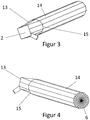
- a mixing rod 1 is an elongate, monolithic body of a transparent material ( 3 and 4 ).
- the mixing rod 1 has a light entry surface 2, a lateral surface 3 and a light exit surface 4.
- An optical axis 5 extends through the center of the light entry surface 2 and the center of the light exit surface 4.
- the light exit surface 4 is substantially convexly curved and composed of several smooth facets 6.
- the light exit surface 4 is formed from six annularly arranged sets of 24 facets 6 each.
- the annularly arranged facets 6 are each planar facets.
- the mixing rod 1 similar to an obelisk, in two sections, in a shape transfer section 13 and in a homogenization section 14, divided.
- the transition between the two sections is given by an interface 15.
- the shape transfer section 13 and the homogenization section 14 are arranged one behind the other along the optical axis.
- the shape transfer section 13 starts with the light entry surface 2 and ends at the interface 15, wherein the interface 15 is formed perpendicular to the optical axis 5.
- the shape transfer section 13 has essentially a constant diameter from the light entry surface 2 in the direction of the light exit surface 4. This changes the shape of the cross-sectional area.
- the light entrance surface 2 corresponds to a planar square and is perpendicular to the optical axis 5.
- the cross section of the mold transfer section 13 corresponds to an Elfeck.
- the shape transfer section 13 may also be formed with a different cross-sectional shape in both the light entry surface 2 and the interface 15.
- the lateral surface 3 of the shape transfer section 13 is formed of eleven planar segments, thereby leading the cross section of a quadrangle in an Elfeck over.
- the homogenization section 14 is arranged after the shape transfer section 13, begins with the interface 15 and ends with the light exit surface 4. In this embodiment, the homogenization section 14 occupies about 80% of the total length between the light entry surface 2 and the light exit surface 4 of the mixing rod 1. Over the entire length of the homogenization section 14, from the boundary surface 15 to the light exit surface 4, its cross-sectional area is constant.
- the shape of the cross section of the homogenization section 14 is constant over its entire length range and corresponds to the shape which forms the shape transfer section 13 at the interface 15. But it is also conceivable that the size of the surface of the cross section remains approximately constant and the shape changes.
- the lateral surface 3 of the homogenization section 14 is formed of eleven planar segments.
- the size of the cross section of the homogenization section 14 has an area of at least 5 mm 2 , preferably at least 10 mm 2 and in particular at least 20 mm 2 .
- the mixing rod may be part of a lighting device 7.
- it also has a light source 8 and a lens 9 ( FIGS. 5 and 6 ).
- Light source 8 and lens 9 are formed as in the previous embodiment.
- a lens is arranged adjacent to the light exit surface of the lens.
- This has in particular holographic, micro and / or nanostructures.
- Microstructures may be, for example, air bubbles embedded in quartz glass.
- the mixing rod may have a section widening in the direction of the exit surface between the homogenization section and the exit surface. With such a widening section, additional bundling of the light beam can take place
- the diameter of the cross-sectional area of the homogenizing section 14 is about 3.5 mm.
- the length of the homogenization section 14 is 40 mm.
- the length and width of the square light entrance surface 4 is 2.4 mm each.
- the different prototypes had shape transfer sections with different lengths of 2 mm, 3 mm, 5 mm and 10 mm.
- the mixing rod with a shape transfer section 13 of 10 mm length results in a light beam with high luminance and good homogenization. With a length of the shape transfer portion of 5 mm, the luminance is good, good at a length of 3 mm and bad at a length of 2 mm.
- the length of the homogenization section is freely selectable per se. The longer the homogenization section, the better the homogenization.
- the shape transfer section 13 can be dispensed with. Then, the homogenizing section 14 has a widening portion and a constant portion.
Abstract
Die vorliegende Erfindung betrifft einen Mischstab zum Mischen eines Lichtstrahlbündels einer inhomogenen Lichtquelle sowie eine Beleuchtungsvorrichtung mit einem solchen Mischstab. Der Mischstab (1) ist aus einem langgestreckten transparenten Körper mit einer Lichteintrittsfläche (2), einer Mantelfläche (3) und einer Lichtaustrittsfläche (4) ausgebildet. Die Lichtaustrittsfläche oder die Lichteintrittsfläche ist im wesentlichen konvex oder konkav gekrümmt geformt. Die Lichtaustrittsfläche bzw. die Lichteintrittsfläche zeichnet sich dadurch aus, dass sie aus mehreren glatten Facetten ausgebildet ist.The present invention relates to a mixing rod for mixing a light beam of an inhomogeneous light source and a lighting device with such a mixing rod. The mixing rod (1) is formed from an elongated transparent body with a light entry surface (2), a lateral surface (3) and a light exit surface (4). The light exit surface or the light entry surface is formed substantially convex or concave curved. The light exit surface or the light entry surface is characterized in that it is formed of several smooth facets.
Description
Die vorliegende Erfindung betrifft einen Mischstab zum Mischen eines Lichtstrahlbündels einer inhomogenen Lichtquelle sowie eine Beleuchtungsvorrichtung mit einem solchen Mischstab.The present invention relates to a mixing rod for mixing a light beam of an inhomogeneous light source and a lighting device with such a mixing rod.
Mischstäbe zum Mischen eines Lichtstrahlbündels sind beispielsweise aus der
Aus der
Aus der
In der
In der
In der
Aus der
In der
In der
In der
Aus der
Aus der
Weiterhin sind Mischstäbe bekannt, welche eine raue Lichtaustrittsfläche aufweisen, so dass das Licht gestreut wird. Hierdurch soll die Durchmischung des Lichtes verbessert werden. Jedoch führen derartige raue Streuflächen zu erheblichen Lichtverlusten.Furthermore, mixing rods are known, which have a rough light exit surface, so that the light is scattered. This is intended to improve the mixing of the light. However, such rough scattered surfaces lead to significant light losses.
Es sind auch Beleuchtungsvorrichtungen bekannt, welche einen Mischstab aufweisen, wobei benachbart zur Lichtaustrittsfläche des Mischstabs zusätzlich eine Streuscheibe vorgesehen ist. Diese Streuscheibe weist zumindest eine raue Oberfläche auf.There are also lighting devices are known which have a mixing rod, wherein adjacent to the light exit surface of the mixing rod additionally a lens is provided. This lens has at least a rough surface.
Der vorliegenden Erfindung liegt die Aufgabe zugrunde, einen Mischstab zum Mischen eines Lichtstrahlbündels einer inhomogenen Lichtquelle sowie eine Beleuchtungsvorrichtung mit einem solchen Mischstab zu schaffen, wobei der Mischstab einfach und kostengünstig herstellbar ist, eine sehr gute Durchmischung des Lichtstrahlbündels in Ort und Richtung bewirkt und dennoch die Lichtverluste gering sind.The present invention has for its object to provide a mixing rod for mixing a light beam of an inhomogeneous light source and a lighting device with such a mixing rod, the mixing rod is simple and inexpensive to produce, causes a very good mixing of the light beam in place and direction and still the Light losses are low.
Eine weitere Aufgabe liegt darin das Lichtstrahlbündel aufzuweiten oder zu bündeln.Another object is to expand or bundle the light beam.
Eine weitere Aufgabe liegt darin den Querschnitt des Lichtstrahlbündels in eine etwa kreisförmige Kontur zu überführen.Another object is to convert the cross section of the light beam in an approximately circular contour.
Die Aufgaben werden durch die Gegenstände der unabhängigen Patentansprüche gelöst. Vorteilhafte Ausgestaltungen sind in den jeweiligen Unteransprüchen angegeben.The objects are achieved by the subject-matter of the independent patent claims. Advantageous embodiments are specified in the respective subclaims.
Ein erfindungsgemäßer Mischstab zum Mischen eines Lichtstrahlbündels einer inhomogenen Lichtquelle ist aus einem langgestreckten transparenten Körper mit einer Lichteintrittsfläche, einer Mantelfläche und einer Lichtaustrittsfläche ausgebildet. Die Lichtaustrittsfläche ist im Wesentlichen konvex geformt und die Lichtaustrittsfläche weist mehrere Facetten auf.A mixing rod according to the invention for mixing a light beam of an inhomogeneous light source is formed from an elongated transparent body having a light entrance surface, a lateral surface and a light exit surface. The light exit surface is substantially convex and the light exit surface has several facets.
Eine derart facettierte Lichtaustrittsfläche steigert die Qualität der Durchmischung des Lichtstrahlbündels erheblich. Die einzelnen Facetten können ebenflächig oder gekrümmt sein. Die Facetten bilden gemeinsam die konvex geformte Lichtaustrittsfläche. Hierdurch wird dem Mischstab eine Linsenfunktion verliehen. Diese konvex oder konkav gekrümmte Lichtaustrittsfläche hat die Wirkung, dass ein virtuelles Bild der Lichtquelle bei konvex geformter Lichtaustrittsfläche ein Stück nach hinten und bei konkaver Krümmung ein Stück nach vorne verschoben wird, wobei nach hinten die Richtung von der Mitte des Mischstabes in Richtung zur Eintrittsfläche und nach vorne in Richtung von der Mitte des Mischstabes zur Austrittsfläche bedeutet. Eine entsprechende Verschiebung des virtuellen Bildes erfolgt auch bei konkaver oder konvexer Ausbildung der Lichteintrittsfläche. Der Mischstab wirkt somit ähnlich wie eine Linse. Dies hat den Vorteil, dass der Mischstab mit einer weiteren Linse kombiniert werden kann, ohne dass die Gefahr besteht, dass die Lichtquelle durch diese Linse exakt abgebildet wird, da durch Verschieben des virtuellen Bildes der Lichtquelle sichergestellt werden kann, dass das virtuelle Bild nicht im Fokus der Linse angeordnet ist. Würde das virtuelle Bild im Fokus der Linse angeordnet sein, dann würde die Durchmischung zumindest zu einem erheblichen Teil aufgehoben werden und Vielfachbilder der Lichtquelle sowie die Strukturen der Lichtquelle in der Lichtstärkeverteilung des Lichtstrahlbündels erkennbar sein. Dies wird unten bei der Beschreibung der Beleuchtungsvorrichtung näher erläutert.Such a faceted light exit surface increases the quality of the mixing of the light beam considerably. The individual facets can be planar or curved. The facets together form the convex shaped light exit surface. As a result, the mixing rod is given a lens function. This convexly or concavely curved light exit surface has the effect that a virtual image of the light source with a convex shaped light exit surface is moved a bit backwards and concave curvature forward a bit, with the direction from the center of the mixing rod towards the entrance surface and means forward in the direction of the center of the mixing rod to the exit surface. A corresponding displacement of the virtual image also takes place with a concave or convex design of the light entry surface. The mixing rod thus acts much like a lens. This has the advantage that the mixing rod can be combined with another lens without the danger that the light source will be accurately imaged by this lens, as moving the virtual image of the light source can ensure that the virtual image is not imaged Focus of the lens is arranged. If the virtual image were to be arranged in the focus of the lens, then the intermixing would be canceled out at least to a considerable extent and multiple images of the light source as well as the structures of the light source would be recognizable in the light intensity distribution of the light beam. This will be explained in more detail below in the description of the lighting device.
Der erfindungsgemäße Mischstab verbindet somit eine sehr gute Mischeigenschaft zum Mischen des Lichtstrahlbündels mit einer hervorragenden Effizienz und ist aufgrund der einfachen Form kostengünstig herstellbar.The mixing rod according to the invention thus combines a very good mixing property for mixing the light beam with an excellent efficiency and is inexpensive to produce due to the simple shape.
Vorzugsweise sind die einzelnen Facetten glatt oder im Wesentlichen glatt. Im Wesentlichen glatt bedeutet, dass der arithmetische Mittenrauwert Ra nicht größer 1,0 µm, vorzugsweise nicht größer als 0,4 µm und insbesondere nicht größer als 0,1 µm ist.Preferably, the individual facets are smooth or substantially smooth. Substantially smooth means that the arithmetic mean roughness Ra is not greater than 1.0 μm, preferably not greater than 0.4 μm, and in particular not greater than 0.1 μm.
Vorzugsweise ist die Lichtaustrittsfläche gekrümmt ausgebildet.Preferably, the light exit surface is curved.
Vorzugsweise ist die gekrümmte Lichtaustrittsfläche oder die gekrümmte Lichteintrittsfläche konvex gekrümmt.Preferably, the curved light exit surface or the curved light entry surface is convexly curved.
Vorzugsweise weist die Lichtaustrittsfläche mehrere Facetten in radialer und/oder Umfangsrichtung auf.The light exit surface preferably has a plurality of facets in the radial and / or circumferential direction.
Der Mischstab kann zumindest im Bereich benachbart zur Lichtaustrittsfläche im Querschnitt die Form eines Polygons aufweisen. Das Polygon weist mehr als vier Ecken, insbesondere mehr als sechs Ecken, vorzugsweise mehr als sieben oder neun oder zehn oder elf oder zwölf oder dreizehn Ecken auf, sodass die Bildebene nicht komplett abgedeckt werden kann. Ein Kreis, beziehungsweise eine Ellipse, ist jedoch kein Polygon im Sinne der vorliegenden Erfindung. Bei einer kreisförmigen oder elliptischen Querschnittsfläche ist die Mischeigenschaft im Vergleich zu einer Polygon-Querschnittsfläche schlechter.The mixing rod may have the shape of a polygon in cross-section at least in the region adjacent to the light exit surface. The polygon has more than four corners, in particular more than six corners, preferably more than seven or nine or ten or eleven or twelve or thirteen corners, so that the image plane can not be completely covered. A circle, or an ellipse, however, is not a polygon in the sense of the present invention. With a circular or elliptical cross-sectional area, the mixing property is inferior as compared with a polygon cross-sectional area.
Bei einer geraden Anzahl von Ecken können Symmetrien bestehen, die die Mischwirkung des Mischstabes 1 beeinträchtigen, daher wird grundsätzlich eine ungerade Anzahl von Ecken bevorzugt.With an even number of corners, there may be symmetries that affect the mixing action of the mixing
Die Querschnittsform kann über die gesamte Länge des Mischstabes gleich sein, wobei die Querschnittsfläche entlang der Längserstreckung des Mischstabes variieren kann.The cross-sectional shape can be the same over the entire length of the mixing rod, wherein the cross-sectional area can vary along the longitudinal extent of the mixing rod.
Der Mischstab ist vorzugsweise von der Lichteintrittsfläche zur Lichtaustrittsfläche konisch aufweitend ausgebildet. Dies führt zu einer Bündelung des Lichtstrahlbündels.The mixing rod is preferably designed to widen conically from the light entry surface to the light exit surface. This leads to a bundling of the light beam.
Nach einem weiteren Aspekt der Erfindung ist der erfindungsgemäße Mischstab derart ausgebildet, dass er zumindest zwei Abschnitte, einen Formüberführungs- und einen Homogenisierungsabschnitt, aufweist. Der Formüberführungsabschnitt und der Homogenisierungsabschnitt sind hintereinander zwischen der Lichteintritts- und der Lichtaustrittsfläche angeordnet. Ein solcher Mischstab liefert bezüglich der Homogenisierung ein besseres Ergebnis als eine gleichmäßige Aufweitung über die gesamte Mischstablänge. Der Mischstab weist im Bereich benachbart zur Lichtaustrittsfläche im Querschnitt die Form eines Polygons auf. Das Polygon weist mehr als vier Ecken auf.According to a further aspect of the invention, the mixing rod according to the invention is designed such that it has at least two sections, a Formüberführungs- and a Homogenisierungsabschnitt. The shape transfer section and the homogenization section are arranged one behind the other between the light entrance and the light exit surface. Such a mixing bar gives a better result with respect to the homogenization than a uniform widening over the entire mixing length. The mixing rod has in the region adjacent to the light exit surface in cross section in the shape of a polygon. The polygon has more than four corners.
Je höher die Anzahl der Ecken ist, desto besser ist die Vermischung. Ist die Kantenlänge des Polygons sollte jedoch nicht kleiner sein als die Wellenlänge des Lichtes, da dadurch die Reflexion beeinträchtigt sein könnte.The higher the number of corners, the better the blending. However, if the edge length of the polygon is not less than the wavelength of the light, it may affect the reflection.
Die Anzahl der Ecken ist vorzugsweise ungerade. Wird Licht durch den Mischstab geleitet, wird das durch eine Kante des Mischstabes im Querschnitt nahezu senkrecht zurückgeworfene Licht anschließend an zumindest zwei weiteren Kanten nochmals zurückgeworfen. Dadurch erhöht sich die Vermischung nochmals.The number of corners is preferably odd. If light is passed through the mixing rod, the light reflected back almost perpendicularly by an edge of the mixing rod in cross section is then thrown back again at at least two further edges. This increases the mixing again.
Ein Kreis, beziehungsweise eine Ellipse, ist jedoch kein Polygon im Sinne der vorliegenden Erfindung. Bei einer kreisförmigen oder elliptischen Querschnittsfläche ist die Mischeigenschaft im Vergleich zu einer Polygon-Querschnittsfläche schlechter.A circle, or an ellipse, however, is not a polygon in the sense of the present invention. With a circular or elliptical cross-sectional area, the mixing property is inferior as compared with a polygon cross-sectional area.
Die Länge des Homogenisierungsabschnittes kann zumindest 20 %, beziehungsweise 40% und vorzugsweise zumindest 50 %, insbesondere zumindest 65 %, und vorzugsweise zumindest 80 % der gesamten Länge des Mischstabes betragen.The length of the homogenization section can be at least 20%, or 40% and preferably at least 50%, in particular at least 65%, and preferably at least 80% of the total length of the mixing rod.
Der Homogenisierungsabschnitt weist im Wesentlichen eine konstante Querschnittsfläche auf, das heißt, dass die Größe der Querschnittsfläche aber nicht notwendigerweise die Form der Querschnittsfläche konstant ist. Die Größe der Querschnittsfläche kann hierbei geringfügig variieren, ohne dass die Homogenisierung beeinträchtigt wird. Insbesondere kann die Querschnittsfläche in Richtung der Lichtaustrittsfläche geringfügig aufweitend oder verjüngend ausgebildet sein.The homogenization section has a substantially constant cross-sectional area, that is, the size of the cross-sectional area but not necessarily the shape of the cross-sectional area is constant. The size of the cross-sectional area may vary slightly without affecting the homogenization. In particular, the cross-sectional area may be formed slightly widening or tapering in the direction of the light exit surface.
Vorzugsweise ist jedoch auch die Form der Querschnittsfläche konstant. Dadurch kann eine bessere Durchmischung des Lichtes erzielt werden, als bei einer diskontinuierlichen oder kontinuierlichen Veränderung der Querschnittsgröße.Preferably, however, the shape of the cross-sectional area is constant. As a result, a better mixing of the light can be achieved, as in a discontinuous or continuous change in the cross-sectional size.
Die Querschnittform weist mehr als fünf Ecken, insbesondere mehr als sechs Ecken, vorzugsweise sieben oder neun oder zehn oder elf oder zwölf oder dreizehn Ecken auf, sodass die Bildebene nicht komplett abgedeckt werden kann. Insbesondere besitzt die Querschnittform vorzugsweise eine ungerade Anzahl von Ecken. Bei einer geraden Anzahl von Ecken können Symmetrien bestehen, die die Mischwirkung des Mischstabes 1 beeinträchtigen.The cross-sectional shape has more than five corners, in particular more than six corners, preferably seven or nine or ten or eleven or twelve or thirteen corners, so that the image plane can not be completely covered. In particular, the cross-sectional shape preferably has an odd number of corners. With an even number of corners, there may be symmetries that affect the mixing action of the mixing
Der Formüberführungsabschnitt kann sich von der Lichteintrittsfläche bis zu einer Grenzfläche mit dem Homogenisierungsabschnitt hin aufweiten. Er kann jedoch auch so ausgebildet sein, dass die Querschnittsfläche des Formüberführungsabschnittes immer in etwa gleich groß ist. Die Grenzfläche ist vorzugsweise parallel zur Lichteintrittsfläche. Im Bereich benachbart zur Lichteintrittsfläche ist es zweckmäßig, eine an die Lichtquelle angepasste Querschnittsform vorzusehen, wie zum Beispiel eine quadratische, rechteckige oder kreisförmige Querschnittsform. Dadurch wird das Etendue zumindest annäherungsweise erhalten, wodurch eine bestmögliche Kollimierung des aus dem Mischstab austretenden Lichtbündels erfolgt. An der Grenzfläche zwischen den beiden Abschnitten ist es zweckmäßig, dass die Form und Größe des Querschnittes der beiden Abschnitte gleich ist, wodurch der Übergang stetig ist und die beiden Abschnitte zueinander bündig sind. Da sich die Form des Querschnittes bei der Lichteintrittsfläche und die Form des Querschnittes bei der Grenzfläche unterscheiden können, ist es zweckdienlich, wenn sich die Form des Querschnittes des Formüberführungsabschnittes dementsprechend allmählich ändert, zum Beispiel von einem Viereck zu einem Elfeck. Ein Elfeck erzeugt eine bessere Farbdurchmischung als ein Viereck. Ein Viereck deckt aber unter Umständen die Form der Lichtquelle ab.The shape transfer section can expand from the light entry surface to an interface with the homogenization section. However, it can also be designed so that the cross-sectional area of the shape transfer section is always approximately the same size. The interface is preferably parallel to the light entry surface. In the region adjacent to the light entry surface, it is expedient to provide a cross-sectional shape adapted to the light source, such as, for example, a square, rectangular or circular cross-sectional shape. As a result, the etendue is at least approximately obtained, whereby the best possible collimation of the emerging from the mixing rod light beam. At the interface between the two sections, it is appropriate that the shape and size of the cross section of the two sections be the same, whereby the transition is continuous and the two sections are flush with each other. Since the shape of the cross section at the light entrance surface and the shape of the cross section at the interface differ Accordingly, it may be convenient if the shape of the cross section of the shape transfer section changes gradually, for example, from a quadrangle to a corner. An Elfeck creates a better color mixing than a square. However, a quadrangle may cover the shape of the light source.
Besitzt der Querschnitt des Lichtstabes eine polygonale Form, dann können die Ecken scharfkantig oder abgerundet ausgebildet sein.If the cross section of the light rod has a polygonal shape, then the corners can be sharp-edged or rounded.
Die Mantelfläche des Mischstabes ist vorzugsweise aus glatten Segmenten ausgebildet, wodurch die Lichtverluste gering gehalten werden.The lateral surface of the mixing rod is preferably formed of smooth segments, whereby the light losses are kept low.
Die Segmente der Mantelflächen können ebenflächig oder leicht gekrümmt sein.The segments of the lateral surfaces can be planar or slightly curved.
Die Länge des Mischstabes beträgt vorzugsweise zumindest 1 cm, insbesondere zumindest 4 cm, bzw. zumindest 8 cm.The length of the mixing rod is preferably at least 1 cm, in particular at least 4 cm, or at least 8 cm.
Das Verhältnis der Länge zum Durchmesser an der Lichteintrittsfläche beträgt zumindest 3:1, insbesondere zumindest 10:1, und vorzugsweise zumindest 15:1. Ist die Lichteintrittsfläche in der Form eines Polygons ausgebildet, dann ist der Durchmesser der Lichteintrittsfläche die größte mögliche Streckenlänge innerhalb des entsprechenden Polygons. Beim Quadrat ist es die Diagonale.The ratio of the length to the diameter at the light entry surface is at least 3: 1, in particular at least 10: 1, and preferably at least 15: 1. If the light entry surface is in the form of a polygon, then the diameter of the light entry surface is the largest possible path length within the corresponding polygon. At the square, it is the diagonal.
Eine Querschnittsfläche des Mischstabes steht grundsätzlich senkrecht zur optischen Achse des Mischstabes. Für die Querschnittsfläche gilt das gleiche wie für die Eintrittsfläche, dass deren Durchmesser die größte mögliche Streckenlänge innerhalb des entsprechenden Polygons ist. Beim Quadrat ist es die Diagonale.A cross-sectional area of the mixing rod is basically perpendicular to the optical axis of the mixing rod. For the cross-sectional area, the same applies as for the entrance surface, that the diameter of which is the largest possible distance within the corresponding polygon. At the square, it is the diagonal.
Eine Aufweitung im Sinne der vorliegenden Erfindung ist die Vergrößerung dieses Durchmessers und eine Verjüngung die Verkleinerung dieses Durchmessers. So kann zum Beispiel bei einer Überführung eines Vierecks zu einem Elfeck in einem Formüberführungsabschnitt sich die Querschnittfläche vergrößern, deren Durchmesser jedoch erhalten bleiben.An expansion in the sense of the present invention is the enlargement of this diameter and a taper the reduction of this diameter. Thus, for example, when transferring a quadrilateral to an ellipse in a mold transfer section, the cross-sectional area increases but the diameters are preserved.
Es hat sich gezeigt, dass je länger der Homogenisierungsabschnitt ist, desto besser ist die Homogenisierung des Lichtes. Deshalb sollte der Formüberführungsabschnitt möglichst kurz und die Aufweitung des Formüberführungsabschnitts möglichst schnell erfolgen.It has been found that the longer the homogenization section, the better the homogenization of the light. Therefore, the shape transfer section should be as short as possible and the widening of the shape transfer section as fast as possible.
Andererseits sollte die Aufweitung des Formüberführungsabschnittes auch nicht zu schnell erfolgen, denn dann kann der durch eine Aufweitung erzielte Effekt der Bündelung des Lichtes beeinträchtigt werden, da ein Teil des Lichtes das unter größeren Eintrittswinkeln an der Lichteintrittsfläche eintritt nicht an der Begrenzungsfläche des Formüberführungsabschnittes reflektiert wird und somit an der Austrittfläche des Mischstabes auch unter entsprechend großem Winkel austritt. Dies hat zur Folge, dass dieses Licht nicht in den gewünschten Zielbereich gelangt.On the other hand, the widening of the shape transfer section should not be too fast, because then the effect achieved by an expansion of the bundling of the light be impaired, since a part of the light entering at larger entrance angles at the light entrance surface is not reflected on the boundary surface of the shape transfer section and thus exits at the exit surface of the mixing rod at a correspondingly large angle. As a result, this light does not reach the desired target area.
Die Länge des Formüberführungsabschnitts kann maximal 30 %, beziehungsweise maximal 25 % und vorzugsweise maximal 20 %, insbesondere maximal 15 %, und vorzugsweise maximal 10 % der gesamten Länge des Mischstabes betragen.The length of the shape transfer section may be at most 30%, or at most 25% and preferably at most 20%, in particular at most 15%, and preferably at most 10% of the total length of the mixing rod.
Der Formüberführungsabschnitt weist vorzugsweise eine Länge auf, die zumindest dem 0,8-fachen des Durchmessers der Eintrittsfläche bzw. zumindest dem 1,2-fachen bzw. zumindest dem 1,5-fachen bzw. zumindest dem 2-fachen bzw. zumindest dem 2,5-fachen des Durchmessers der Eintrittsfläche entspricht. Ist die Lichteintrittsfläche in der Form eines Polygons ausgebildet, dann ist der Durchmesser der Lichteintrittsfläche wieder die größte mögliche Streckenlänge innerhalb des entsprechenden Polygons.The shape transfer section preferably has a length which is at least 0.8 times the diameter of the entry surface or at least 1.2 times, or at least 1.5 times, or at least 2 times, or at least 2 , 5 times the diameter of the entrance surface corresponds. If the light entry surface is in the form of a polygon, then the diameter of the light entry surface is again the largest possible route length within the corresponding polygon.
Statt einer festen Trennung zwischen den beiden Abschnitten, kann es vorteilhaft sein, dass die Aufweitung allmählich über die gesamte Länge des Mischstabes erfolgt. Beispielsweise kann die Aufweitung sich von der Eintrittsfläche zur Austrittsfläche etwa exponentiell abschwächen. Eventuelle ungewünschte Effekte durch die Übergangsregion können sich so vermeiden lassen. Der Formüberführungsabschnitt stellt den Bereich dar, in dem die Form der Eintrittsfläche auf die Querschnittsform des Homogenisierungsabschnitts überführt wird. Es kann auch ein Bereich zwischen den beiden Abschnitten vorgesehen sein, in dem sich z.B. der Mischstab nicht aufweitet aber der Übergang zwischen den unterschiedlichen Querschnittsformen noch nicht abgeschlossen ist. Ein solcher Abschnitt wird als Übergangsabschnitt bezeichnet.Instead of a fixed separation between the two sections, it may be advantageous for the expansion to take place gradually over the entire length of the mixing rod. For example, the expansion can weaken about exponentially from the entrance surface to the exit surface. Any unwanted effects caused by the transition region can be avoided in this way. The shape transfer section represents the area in which the shape of the entrance surface is converted to the cross-sectional shape of the homogenization section. There may also be provided an area between the two sections in which e.g. the mixing rod does not expand but the transition between the different cross-sectional shapes has not yet been completed. Such a section is called a transition section.
Der Mischstab ist vorzugsweise aus einem transparenten Kunststoff ausgebildet. Grundsätzlich kann er auch aus Glas ausgebildet sein. Das bevorzugte Material ist jedoch ein Kunststoff auf Silikonbasis oder PMMA, beziehungsweise PMMI. Dieses Material ist einfach verarbeitbar, besitzt eine hohe Transparenz, wodurch die Lichtverluste gering gehalten werden und ist langzeitstabil und UV-stabil. Kunststoff auf Silikonbasis und PMMI sind auch temperaturunempfindlich.The mixing rod is preferably formed of a transparent plastic. In principle, it can also be made of glass. However, the preferred material is a silicone-based plastic or PMMA or PMMI. This material is easy to process, has a high transparency, whereby the light losses are kept low and is long-term stable and UV-stable. Silicone-based plastic and PMMI are also insensitive to temperature.
Nach einem weiteren Aspekt der vorliegenden Erfindung ist eine Beleuchtungsvorrichtung vorgesehen, welche eine Lichtquelle, einen Mischstab und eine Linse aufweist. Der Mischstab entspricht einem der oben erläuterten Mischstäbe und ist mit seiner Lichteintrittsfläche in Richtung zur Lichtquelle weisend angeordnet.According to a further aspect of the present invention, a lighting device is provided which comprises a light source, a mixing rod and a lens. The mixing rod corresponds to one of the above-explained mixing rods and is arranged pointing with its light entry surface in the direction of the light source.
Die Linse ist vorzugsweise entlang einer optischen Achse des korrespondierenden Mischstabes verschieblich und benachbart zur Lichtaustrittsfläche angeordnet.The lens is preferably displaceable along an optical axis of the corresponding mixing rod and arranged adjacent to the light exit surface.
Auch die Linse ist vorzugsweise aus einem transparenten Kunststoff, insbesondere Silikon, ausgebildet.The lens is preferably made of a transparent plastic, in particular silicone.
Silikon besitzt neben dem Vorteil der Temperaturunempfindlichkeit auch den Vorteil dass die Linse einfach und kostengünstig zu fertigen ist. Im Gegensatz dazu wird für gewöhnlichen Kunststoff eine relativ große Anspritzfläche benötigt, die unter Umständen in die optischen Flächen hineinragen kann. Des Weiteren muss bei dicken Linsen aus gewöhnlichem Kunststoff entsprechend nachgedrückt werden, was die Zykluszeit verlängert und damit die Kosten erhöht.In addition to the advantage of temperature insensitivity, silicone also has the advantage that the lens can be produced simply and inexpensively. In contrast, a relatively large Anspritzfläche is required for ordinary plastic, which may possibly protrude into the optical surfaces. Furthermore, with thick lenses made of ordinary plastic must be pressed accordingly, which extends the cycle time and thus increases the cost.
Durch Verschieben der Linse kann der Strahlkegel, mit welchem das von der Beleuchtungsvorrichtung austretende Lichtstrahlbündel abgeleitet wird, unterschiedlich eingestellt werden. Durch eine konvexe oder konkave Form der Lichtaustrittsfläche des Mischstabs erzeugt dieser bei entsprechender Wahl der Krümmung ein virtuelles Bild der Lichtquelle, das sich nicht in der Nähe oder innerhalb des Fokusbereichs der Linse befindet, was bei einem Mischstab mit planer Austrittsfläche der Fall sein könnte. Ein virtuelles Bild der Lichtquelle, welches sich in der Nähe oder innerhalb des Fokusbereichs der Linse befindet, sollte möglichst vermieden werden, da hierdurch die Mischung des Lichtstrahlbündels durch den Mischstab zumindest zu einem Teil wieder aufgehoben wird. Vorzugsweise beträgt der Abstand zwischen dem Fokus der Linse und des durch den Mischstab erzeugten virtuellen Bildes zumindest 1 mm, vorzugsweise zumindest 1 cm und insbesondere zumindest 5cm. Die Begrenzung des Verschiebebereiches ist derart ausgebildet, dass ein Abstand zwischen dem Fokus der Linse und des durch den Mischstab erzeugten virtuellen Bildes bestehen bleibt.By shifting the lens, the beam cone, with which the light beam exiting from the illumination device is derived, can be adjusted differently. By means of a convex or concave shape of the light exit surface of the mixing rod, the latter, with a suitable choice of curvature, generates a virtual image of the light source which is not in the vicinity or within the focus range of the lens, which could be the case with a mixing rod with a planar exit surface. A virtual image of the light source, which is located in the vicinity of or within the focus range of the lens, should be avoided as far as possible, since in this way the mixture of the light beam through the mixing rod is at least partially canceled out. Preferably, the distance between the focus of the lens and the virtual image generated by the mixing rod is at least 1 mm, preferably at least 1 cm and in particular at least 5 cm. The boundary of the displacement region is designed such that a distance between the focus of the lens and the virtual image generated by the mixing rod remains.
Vorzugsweise ist bzw. sind entlang der optischen Achse im Bereich zwischen der Lichtquelle und der Linse außer dem Mischstab kein weiteres optisches Element, insbesondere keine weiteren optischen Elemente zur Durchmischung, angeordnet. Durch die Ausgestaltung des Mischstabes sind auch keine weiteren optischen Elemente, wie zum Beispiel Streuscheiben, notwendig, um eine ausreichende Durchmischung des Lichtstrahlbündels zu erhalten.Preferably, no further optical element, in particular no further optical elements for mixing, is or are arranged along the optical axis in the region between the light source and the lens other than the mixing rod. Due to the configuration of the mixing rod, no further optical elements, such as scattering disks, are necessary in order to obtain a sufficient mixing of the light beam.
Die Lichtquelle weist vorzugsweise mehrere Leuchtdioden bzw. eine Leuchtdiode mit mehreren Leuchtflächen auf. Die Beleuchtungsvorrichtung macht jedoch auch Sinn für andere inhomogene Lichtquellen, gekennzeichnet durch eine inhomogene spezifische Lichtausstrahlung und/oder eine inhomogene Farbverteilung und/oder eine inhomogene Richtungsverteilung.The light source preferably has a plurality of light emitting diodes or a light emitting diode with a plurality of illuminated surfaces. However, the lighting device also makes sense for other inhomogeneous Light sources, characterized by an inhomogeneous specific light emission and / or an inhomogeneous color distribution and / or an inhomogeneous directional distribution.
Die Beleuchtungsvorrichtung kann mehrere Mischstäbe aufweisen, welchen jeweils zumindest eine Lichtquelle zugeordnet ist. Jedem Mischstab kann eine separate Linse zugeordnet sein. Die Linsen werden gemeinsam oder gruppenweise entlang der optischen Achse der einzelnen Mischstäbe verfahren. Es kann jedoch auch eine gemeinsame Linse vorgesehen sein, welche die Lichtaustrittsflächen aller Mischstäbe abdecktThe lighting device may have a plurality of mixing rods, which are each assigned at least one light source. Each mixing rod may be associated with a separate lens. The lenses are moved together or in groups along the optical axis of the individual mixing rods. However, it can also be provided a common lens, which covers the light exit surfaces of all mixing rods
Des Weiteren kann die Beleuchtungsvorrichtung benachbart zur Lichtaustrittsfläche der Linse eine Streuscheibe aufweisen, welche vorzugsweise holographische, Mikro- und/oder Nanostrukturen aufweist. Dadurch werden sowohl weichere Helligkeitsverläufe (sogenanntes "Absoften") in den Randbereichen des Lichtstrahlbündels ermöglicht als auch eine Glättung der Außenkontur des Lichtstrahlbündels bei Beleuchtungsvorrichtungen, welche mehr als einen Mischstab aufweisen. Durch diese Positionierung der Streuscheibe treten keine signifikanten Lichtverluste auf.Furthermore, the illumination device adjacent to the light exit surface of the lens may have a diffusing screen, which preferably has holographic, micro and / or nanostructures. As a result, both softer brightness gradients (so-called "flattening") in the edge regions of the light beam are made possible as well as a smoothing of the outer contour of the light beam in lighting devices which have more than one mixing rod. Due to this positioning of the lens no significant light losses occur.
Die Erfindung wird beispielhaft näher anhand der Zeichnungen erläutert. Die Zeichnungen zeigen schematisch in:
Figur 1- einen Mischstab in perspektivischer Ansicht, und
Figur 2- eine Beleuchtungsvorrichtung in einer Seitenansicht.
Figur 3- einen Mischstab in perspektivischer Ansicht,
- Figur 4
- einen Mischstab in einer anderen perspektivischer Ansicht,
Figur 5- einen Mischstab und eine Linse in einer Seitenansicht, und
Figur 6- einen Mischstab und eine Linse in perspektivischer Ansicht.
- FIG. 1
- a mixing rod in perspective view, and
- FIG. 2
- a lighting device in a side view.
- FIG. 3
- a mixing rod in perspective view,
- FIG. 4
- a mixing stick in another perspective view,
- FIG. 5
- a mixing rod and a lens in a side view, and
- FIG. 6
- a mixing rod and a lens in perspective view.
Ein erfindungsgemäßer Mischstab 1 ist ein langgestreckter, monolithischer Körper aus einem transparenten Material (
Eine optische Achse 5 erstreckt sich durch den Mittelpunkt der Lichteintrittsfläche 2 und den Mittelpunkt der Lichtaustrittsfläche 4.An
Im vorliegenden ersten Ausführungsbeispiel (
Die Lichtaustrittsfläche 4 ist im Wesentlichen konvex gekrümmt und aus mehreren glatten Facetten 6 zusammengesetzt. Im vorliegenden Ausführungsbeispiel ist die Lichtaustrittsfläche 4 aus zwei ringförmig angeordneten Sätzen von jeweils sieben Facetten 6/1 bzw. 6/2 und einer zentralen Facette 6/3 ausgebildet. Die ringförmig angeordneten Facetten 6/1 und 6/2 sind jeweils ebenflächige Facetten, wobei die zentrale Facette 6/3 eine leichte konvexe Wölbung aufweist.The light exit surface 4 is substantially convexly curved and composed of several
Der Mischstab 1 besitzt einen polygonalen Querschnitt, wobei der Querschnitt im vorliegenden Ausführungsbeispiel ein Siebeneck (Heptagon) ist. Dementsprechend ist die Mantelfläche 3 aus sieben ebenflächigen Segmenten ausgebildet.The mixing
Der Mischstab 1 kann jedoch auch mit einer anderen Querschnittsform ausgebildet sein. Bevorzugt sind Polygone mit mehr als vier, insbesondere mehr als sechs Ecken, sie weisen vorzugsweise sieben oder neun oder zehn oder elf oder zwölf oder dreizehn Ecken auf. Insbesondere besitzt das Polygon vorzugsweise eine ungerade Anzahl von Ecken.However, the mixing
Die Polygone sind vorzugsweise regelmäßige Polygone.The polygons are preferably regular polygons.
Im vorliegenden Ausführungsbeispiel ist die Lichteintrittsfläche 2 ebenflächig ausgebildet. Im Rahmen der Erfindung kann es zweckmäßig sein, dass auch die Lichteintrittsfläche 2 konkav oder konvex gewölbt ist.In the present embodiment, the
Die Querschnittsfläche ist an der Lichteintrittsfläche 2 kleiner als an der Lichtaustrittsfläche 4, so dass sich der Mischstab von der Lichteintrittsfläche 2 zur Lichtaustrittsfläche 4 konisch aufweitet.The cross-sectional area is smaller at the
Eine Beleuchtungsvorrichtung 7 mit einem Mischstab 1, wie er zuvor beschrieben wurde, weist zusätzlich noch eine Lichtquelle 8 und eine Linse 9 auf (
Die Linse 9 ist benachbart zur Lichtaustrittsfläche 4 des Mischstabes 1 angeordnet. Die Linse 9 ist konzentrisch zur optischen Achse 5 des Mischstabes angeordnet und ist entlang der optischen Achse 5 beweglich. Hierzu sind geeignete Führungselemente vorgesehen, welche dem Fachmann bekannt sind und zur einfacheren zeichnerischen Darstellung in
Die Linse 9 ist vorzugsweise auch aus einem Kunststoffmaterial, insbesondere einem Kunststoffmaterial auf Silikonbasis ausgebildet. Die Linse 9 kann sehr nahe an die Lichtaustrittsfläche 4 bewegt werden. Je näher sich die Linse 9 an der Lichtaustrittsfläche 4 befindet, desto stärker wird die Aufweitung des Kegels des Lichtstrahlbündels durch Bewegen der Linse verändert. Daher ist es zweckmäßig, dass sich keine weiteren optischen Elemente im Bereich zwischen der Lichtaustrittsfläche 4 und der Linse 9 befinden, so dass die Linse 9 bis zur Lichtaustrittsfläche 4 bewegt werden kann. Ein möglichst großer einstellbarer Winkelbereich ist sehr von Vorteil.The
Die Lichtaustrittsfläche 4 besitzt eine Doppelfunktion, indem sie einerseits durch die Wölbung eine Linsenfunktion des Mischstabes 1 bewirkt und andererseits durch das Vorsehen der mehreren Facetten 6 die Durchmischung des Lichtstrahlbündels fördert.The light exit surface 4 has a dual function, on the one hand by the curvature causes a lens function of the mixing
Der Mischstab 1 weist vorzugsweise zumindest vier Facetten, insbesondere zumindest zehn Facetten und besonders bevorzugt zumindest fünfzehn Facetten auf. Die Anzahl der Facetten am Austritt sollte jedoch nicht größer als 200 und insbesondere nicht größer als 150, beziehungsweise nicht größer als 100 sein. Die maximale Anzahl der Facetten kann durch das Herstellungsverfahren begrenzt sein. Beim Spritzgießen sind kleine Facetten nicht darstellbar und ergeben eine mehr oder weniger gleichmäßig gekrümmte Oberfläche, wodurch die durchmischende Wirkung der Facettierung reduziert wird.The mixing
Weiterhin wird durch die polygonale Form des Querschnittes des Mischstabes 1 mit insbesondere einer ungeraden Anzahl von Ecken des Mischstabes 1 die Durchmischung des Lichtstrahlbündels verstärkt.Furthermore, the mixing of the light beam is enhanced by the polygonal shape of the cross section of the mixing
Da sowohl die Mantelfläche 3 aus glatten Segmenten als auch die Lichtaustrittsfläche 4 aus glatten Facetten 6 zusammengesetzt sind, sind die Lichtverluste am Mischstab 1 sehr gering.Since both the
Somit wird eine Beleuchtungsvorrichtung geschaffen, bei welcher auf einfache Art und Weise Licht einer inhomogenen Lichtquelle sehr gut gemischt wird, die Lichtverluste gering sind und die Aufweitung des Lichtstrahlbündels über einen großen Bereich durch Verschieben der Linse 9 einstellbar ist.Thus, a lighting device is provided in which light of an inhomogeneous light source is mixed very well in a simple manner, the light losses are small and the expansion of the light beam over a large range by moving the
Die Beleuchtungsvorrichtung kann auch mehrere Mischstäbe aufweisen, wobei jedem Mischstab zumindest eine Lichtquelle zugeordnet ist. Die einzelnen Mischstäbe sind vorzugsweise zueinander parallel angeordnet. Die einzelnen Mischstäbe sind vorzugsweise identisch ausgebildet. Jedem Mischstab kann eine separate Linse zugeordnet sein. Die Linsen werden gemeinsam oder gruppenweise entlang der optischen Achse der einzelnen Mischstäbe verfahren. Es kann jedoch auch eine gemeinsame Linse vorgesehen sein, welche die Lichtaustrittsflächen aller Mischstäbe abdeckt.The lighting device may also have a plurality of mixing rods, wherein each mixing rod is associated with at least one light source. The individual mixing rods are preferably arranged parallel to one another. The individual mixing rods are preferably identical. Each mixing rod may be associated with a separate lens. The lenses are moved together or in groups along the optical axis of the individual mixing rods. However, it can also be provided a common lens, which covers the light exit surfaces of all mixing rods.
Im Nachfolgenden wird ein zweites Ausführungsbeispiel erläutert. Gleiche Bauteile sind mit gleichen Bezugszeichen versehen. Sofern nachfolgend nichts anderes ausgeführt ist, gelten die entsprechenden Beschreibungen und Erläuterungen des ersten Ausführungsbeispiels auch für das zweite Ausführungsbeispiel.Hereinafter, a second embodiment will be explained. Identical components are provided with the same reference numerals. Unless stated otherwise below, the corresponding descriptions and explanations of the first embodiment also apply to the second embodiment.
Ein Mischstab 1 ist ein langgestreckter, monolithischer Körper aus einem transparenten Material (
Eine optische Achse 5 erstreckt sich durch den Mittelpunkt der Lichteintrittsfläche 2 und den Mittelpunkt der Lichtaustrittsfläche 4.An
Die Lichtaustrittsfläche 4 ist im Wesentlichen konvex gekrümmt und aus mehreren glatten Facetten 6 zusammengesetzt. Im vorliegenden Ausführungsbeispiel ist die Lichtaustrittsfläche 4 aus sechs ringförmig angeordneten Sätzen von jeweils 24 Facetten 6 ausgebildet. Die ringförmig angeordneten Facetten 6 sind jeweils ebenflächige Facetten.The light exit surface 4 is substantially convexly curved and composed of several
Im vorliegenden Ausführungsbeispiel ist der Mischstab 1, ähnlich wie bei einem Obelisken, in zwei Abschnitte, in einen Formüberführungsabschnitt 13 und in einen Homogenisierungsabschnitt 14, unterteilt. Der Übergang zwischen den beiden Abschnitten ist durch eine Grenzfläche 15 gegeben.In the present embodiment, the mixing
Der Formüberführungsabschnitt 13 und der Homogenisierungsabschnitt 14 sind entlang der optischen Achse hintereinander angeordnet. Der Formüberführungsabschnitt 13 fängt mit der Lichteintrittsfläche 2 an und endet an der Grenzfläche 15, wobei die Grenzfläche 15 senkrecht zur optischen Achse 5 ausgebildet ist.The
Der Formüberführungsabschnitt 13 weist von der Lichteintrittsfläche 2 in Richtung der Lichtaustrittsfläche 4 im Wesentlichen einen konstanten Durchmesser auf. Hierbei ändert sich die Form der Querschnittsfläche. Im vorliegenden Ausführungsbeispiel entspricht die Lichteintrittsfläche 2 einem ebenflächigen Quadrat und steht senkrecht zur optischen Achse 5. Am Ende des Formüberführungsabschnittes 13 an der Grenzfläche 15 entspricht der Querschnitt des Formüberführungsabschnittes 13 einem Elfeck. Der Formüberführungsabschnitt 13 kann jedoch sowohl bei der Lichteintrittsfläche 2 als auch bei der Grenzfläche 15 auch mit einer anderen Querschnittsform ausgebildet sein.The
Die Mantelfläche 3 des Formüberführungsabschnittes 13 ist aus elf ebenflächigen Segmenten ausgebildet und führt dabei den Querschnitt von einem Viereck in ein Elfeck über.The
Der Homogenisierungsabschnitt 14 ist nach dem Formüberführungsabschnitt 13 angeordnet, beginnt mit der Grenzfläche 15 und endet mit der Lichtaustrittsfläche 4. Der Homogenisierungsabschnitt 14 nimmt in diesem Ausführungsbeispiel dabei etwa 80 % der gesamten Länge zwischen der Lichteintrittsfläche 2 und der Lichtaustrittsfläche 4 des Mischstabes 1 ein. Über der gesamten Länge des Homogenisierungsabschnittes 14, von der Grenzfläche 15 bis hin zur Lichtaustrittsfläche 4, ist dessen Querschnittsfläche konstant.The
Im vorliegenden Ausführungsbeispiel ist auch die Form des Querschnittes des Homogenisierungsabschnittes 14 über seinen gesamten Längenbereich konstant und entspricht der Form, welche der Formüberführungsabschnitt 13 an der Grenzfläche 15 bildet. Es ist aber auch denkbar, dass die Größe der Fläche des Querschnittes in etwa konstant bleibt und die Form sich ändert.In the present embodiment, the shape of the cross section of the
Im vorliegenden Ausführungsbeispiel ist die Mantelfläche 3 des Homogenisierungsabschnittes 14 aus elf ebenflächigen Segmenten ausgebildet.In the present embodiment, the
Vorzugsweise weist die Größe des Querschnittes des Homogenisierungsabschnittes 14 eine Fläche von zumindest 5 mm2, vorzugsweise zumindest 10 mm2 und insbesondere zumindest 20 mm2 auf.Preferably, the size of the cross section of the
Wie im vorangegangenen Ausführungsbeispiel kann der Mischstab Teil einer Beleuchtungsvorrichtung 7 sein. Zusätzlich zum Mischstab 1, weist sie noch eine Lichtquelle 8 und eine Linse 9 auf (
Eine weitere Möglichkeit der Erfindung besteht darin, dass benachbart zur Lichtaustrittsfläche der Linse eine Streuscheibe angeordnet ist. Diese weist insbesondere holographische, Mikro- und/oder Nanostrukturen auf. Mikrostrukturen können zum Beispiel in Quarzglas eingelassene Luftbläschen sein.Another possibility of the invention is that a lens is arranged adjacent to the light exit surface of the lens. This has in particular holographic, micro and / or nanostructures. Microstructures may be, for example, air bubbles embedded in quartz glass.
Der Mischstab kann zwischen dem Homogenisierungsabschnitt und der Austrittsfläche einen sich in Richtung zur Austrittsfläche aufweitenden Abschnitt aufweisen. Mit einem solchen Aufweitungsabschnitt kann eine zusätzliche Bündelung des Lichtstrahlbündels erfolgenThe mixing rod may have a section widening in the direction of the exit surface between the homogenization section and the exit surface. With such a widening section, additional bundling of the light beam can take place
Von dem oben erläuterten Ausführungsbeispiel mit einer quadratischen Lichteintrittsfläche 2 und einer elfeckigen Lichtaustrittsfläche 4 wurden unterschiedliche Prototypen mit unterschiedlich langem Formüberführungsabschnitt 13 hergestellt. Der Durchmesser der Querschnittsfläche des Homogenisierungsabschnitts 14 beträgt etwa 3,5 mm. Die Länge des Homogenisierungsabschnitts 14 beträgt 40 mm. Die Länge und Breite der quadratischen Lichteintrittsfläche 4 beträgt jeweils 2,4 mm. Die unterschiedlichen Prototypen wiesen Formüberführungsabschnitte mit unterschiedlichen Längen von 2 mm, 3 mm, 5 mm und 10 mm auf. Der Mischstab mit einem Formüberführungsabschnitt 13 von 10 mm Länge ergibt ein Lichtstrahlbündel mit hoher Leuchtdichte und guter Homogenisierung. Bei einer Länge des Formüberführungsabschnittes von 5 mm ist die Leuchtdichte gut, bei einer Länge von 3 mm in Ordnung und bei einer Länge von 2 mm schlecht.From the exemplary embodiment explained above with a square
Die Länge des Homogenisierungsabschnittes ist an sich frei wählbar. Je länger der Homogenisierungsabschnitt ist, desto besser ist die Homogenisierung.The length of the homogenization section is freely selectable per se. The longer the homogenization section, the better the homogenization.
Ist die Form der Lichteintrittsfläche 2 gleich der Form des Querschnittest des Homogenisierungsabschnitts 14, kann auf den Formüberführungsabschnitt 13 verzichtet werden. Dann hat der Homogenisierungsabschnitt 14 einen aufweitenden und einen konstanten Abschnitt.
Claims (15)
die gekrümmte Lichtaustrittsfläche (4) und/oder gekrümmte Lichteintrittsfläche (2) mehrere Facetten (6) aufweist.Mixing rod for mixing a light beam of an inhomogeneous light source (8), wherein the mixing rod (1) consists of an elongate transparent body with a light entrance surface (2), a lateral surface (3) and a light exit surface (4), wherein the light exit surface (4) and / or the light entry surface (2) is / are substantially convex or concavely curved, and
the curved light exit surface (4) and / or curved light entry surface (2) has a plurality of facets (6).
dadurch gekennzeichnet,
dass die Facetten glatt oder im Wesentlichen glatt sind.Mixing rod according to claim 1,
characterized,
that the facets are smooth or substantially smooth.
dadurch gekennzeichnet,
dass die Lichtaustrittsfläche (4) mehrere Facetten (6) in radialer und/oder Umfangsrichtung aufweist.Mixing rod according to one of claims 1 or 2,
characterized,
that the light exit surface (4) having a plurality of facets (6) in the radial and / or circumferential direction.
dadurch gekennzeichnet,
dass der Mischstab (1) von der Lichteintrittsfläche (2) zur Lichtaustrittsfläche (4) mit zunehmenden Durchmesser der Querschnittsfläche ausgebildet ist.Mixing rod according to one of claims 1 to 3,
characterized,
that the mixing rod (1) from the light entrance surface (2) to the light exit surface (4) is formed with increasing diameter of the cross-sectional area.
zum Mischen eines Lichtstrahlbündels einer inhomogenen Lichtquelle (8),
wobei der Mischstab (1) aus einem langgestreckten transparenten Körper mit einer Lichteintrittsfläche (2), einer Mantelfläche (3) und einer Lichtaustrittsfläche (4) ausgebildet ist, wobei der Mischstab (1) in Längsrichtung einen Formüberführungsabschnitt (13),
welcher die Form der Querschnittsfläche von der Lichteintrittsfläche (2) zur Grenzfläche (15) des Homogenisierungsabschnittes (14) in eine andere Form überführt,
und einen Homogenisierungsabschnitt (14) umfasst, welcher in Richtung von der Lichteintrittsfläche (2) zur Lichtaustrittsfläche (4) im Wesentlichen eine konstante Querschnittsfläche und im Wesentlichen eine konstante Querschnittsform aufweist,
wobei der Mischstab (1) zumindest im Bereich benachbart zur Lichtaustrittsfläche (4) im Querschnitt die Form eines Polygons und vorzugsweise eines Polygons mit einer ungeraden Anzahl von Ecken aufweist, wobei das Polygon mehr als vier Ecken aufweist.Mixing rod, in particular according to one of claims 1 to 4,
for mixing a light beam of an inhomogeneous light source (8),
wherein the mixing rod (1) is formed from an elongated transparent body having a light entry surface (2), a lateral surface (3) and a light exit surface (4), wherein the mixing rod (1) has a shape transfer section (13) in the longitudinal direction,
which converts the shape of the cross-sectional area from the light entry surface (2) to the interface (15) of the homogenization section (14) in another form,
and a homogenization section (14) having a substantially constant cross-sectional area and a substantially constant cross-sectional shape in the direction from the light entry surface (2) to the light exit surface (4),
wherein the mixing bar (1) at least in the region adjacent to the light exit surface (4) in cross section has the shape of a polygon and preferably a polygon with an odd number of corners, the polygon having more than four corners.
dadurch gekennzeichnet,
dass der Formüberführungsabschnitt (13) von der Lichteintrittsfläche (2) zur Grenzfläche (15) des Homogenisierungsabschnittes (14) mit zunehmenden Durchmesser der Querschnittsfläche ausgebildet ist, und/oder,
dass die Länge des Homogenisierungsabschnittes (14) zumindest 30 %, beziehungsweise 40 % und vorzugsweise zumindest 50 %, insbesondere zumindest 65 % und vorzugsweise zumindest 80 % der gesamten Länge des Mischstabes (1) beträgt.Mixing rod according to claim 5,
characterized,
that the shape of the transfer portion (13) of the light entry surface (2) to the boundary surface (15) of Homogenisierungsabschnittes (14) is formed with increasing diameter of the cross-sectional area, and / or,
that the length of Homogenisierungsabschnittes (14) at least 30%, and 40% and preferably at least 50%, especially at least 65% and preferably at least 80% of the total length of the mixing rod (1).
dadurch gekennzeichnet,
dass der Homogenisierungsabschnitt (14) des Mischstabes (1) in Richtung von der Lichteintrittsfläche (2) bis zur Lichtaustrittsfläche (4) eine im Wesentlichen konstante Querschnittsform aufweist, und/oder,
dass der Formüberführungsabschnitt (13) und der Homogenisierungsabschnitt (14) an einer gemeinsamen Grenzfläche (15) bündig ausgebildet sind.Mixing rod according to claim 5 or 6,
characterized,
that the Homogenisierungsabschnitt (14) of the mixing rod (1) in the direction of the light entry surface (2) to the light exit surface (4) has a substantially constant cross-sectional shape, and / or,
in that the shape transfer section (13) and the homogenization section (14) are designed to be flush at a common interface (15).
dadurch gekennzeichnet,
dass die Querschnittsform des Formüberführungsabschnittes (13) von der Lichteintrittsfläche (2) in Richtung der Lichtaustrittsfläche (4) sich von einem Polygon, insbesondere von einem Quadrat, zu einem anderen Polygon verformt, und/oder,
dass das Polygon mehr als 5 Ecken und vorzugsweise 7 oder 9 oder 11 oder 13 Ecken aufweist, und/oder,
dass der Mischstab über die gesamte Länge des Mischstabes aufweitend ausgebildet ist, wobei die Vergrößerung des Durchmessers der Querschnittsfläche sich von der Eintrittsfläche (2) zur Austrittsfläche (4) vorzugsweise etwa exponentiell abschwächt..Mixing rod according to one of claims 5 to 7,
characterized,
that the cross-sectional shape of the mold transfer section (13) of the light entry surface (2) in the direction of the light exit surface (4) is of a polygon, in particular of a square, deformed to another polygon, and / or,
that the polygon has more than 5 vertices, and preferably 7 or 9 or 11 or 13 corners, and / or,
that the mixing rod is formed divergently over the entire length of the mixing rod, with the increase in the diameter of the cross-sectional area of the entrance surface (2) to the exit surface (4) attenuates preferably approximately exponentially ..
dadurch gekennzeichnet,
dass die Mantelfläche (3) aus glatten Segmenten ausgebildet ist, und/oder,
dass die Länge des Mischstabes (1) zumindest 1 cm, vorzugsweise zumindest 5 cm und insbesondere zumindest 10 cm beträgt, und/oder,
dass das Verhältnis der Länge zum Durchmesser an der Lichteintrittsfläche (4) zumindest 3:1, insbesondere zumindest 10:1 und vorzugsweise zumindest 15:1 beträgt.Mixing rod according to one of claims 1 to 8,
characterized,
that the lateral surface (3) is formed of smooth segments, and / or
that the length of the mixing rod (1) is at least 1 cm, preferably at least 5 cm and especially at least 10 cm, and / or,
that the ratio of length to diameter of the light entry surface (4) at least 3: 1, in particular at least 10: 1 and preferably at least 15: 1.
dadurch gekennzeichnet,
dass der Mischstab (1) aus Kunststoff, insbesondere aus einem Kunststoff auf Silikonbasis oder PMMI oder PMMA ausgebildet ist.Mixing rod according to one of claims 1 to 9,
characterized,
that the mixing rod (1) made of plastic, in particular of a silicone-based plastic or PMMI or PMMA is formed.
dadurch gekennzeichnet,
dass der Querschnitt der Lichteintrittsfläche (2) des Mischstabes (1) in der Form ein Polygon ist,
welche der Grundform der Lichtquelle (8) entspricht,
und in der Größe derart ausgebildet ist, dass er die Lichtquelle (8) umfasst,
wobei der Durchmesser der Querschnittsfläche höchstens 50 %, insbesondere höchstens 30 % und vorzugsweise höchstens 15 % größer ist als die Grundfläche der Lichtquelle (8).Lighting device according to claim 11,
characterized,
that the cross section of the light entry surface (2) of the mixing rod (1) in the form is a polygon,
which corresponds to the basic form of the light source (8),
and is sized to include the light source (8),
wherein the diameter of the cross-sectional area is at most 50%, in particular at most 30% and preferably at most 15% greater than the base area of the light source (8).
dadurch gekennzeichnet,
dass die Linse (9) in Richtung einer optischen Achse (5) des korrespondierenden Mischstabes (1) verschiebbar ausgebildet ist, und/oder,
dass die Linse (9) derart eine Brennweite aufweist,
so dass der Abstand zwischen dem Fokus der Linse (9) und des durch den Mischstab (1) erzeugten virtuellen Bildes zumindest 1 mm, vorzugsweise zumindest 1 cm und insbesondere zumindest 5 cm beträgt, und/oder,
dass die Linse (9) vorzugsweise asphärisch ausgebildet ist.Lighting device according to claim 11 or 12,
characterized,
that the lens (9) in the direction of an optical axis (5) of the corresponding mixing rod (1) is designed to be displaceable, and / or,
that the lens (9) in such a manner has a focal length,
such that the distance between the focus of the lens (9) and the virtual image generated by the mixing rod (1) is at least 1 mm, preferably at least 1 cm and in particular at least 5 cm, and / or
that the lens (9) is preferably formed aspherical.
dadurch gekennzeichnet,
dass entlang der optischen Achse (5) im Bereich zwischen der Lichtquelle (8) und der beweglichen Linse (9) außer dem Mischstab (1) keine weiteren optischen Elemente zur Durchmischung angeordnet sind.Lighting device according to one of claims 11 to 13,
characterized,
in that no further optical elements for mixing are arranged along the optical axis (5) in the region between the light source (8) and the movable lens (9) except for the mixing rod (1).
dadurch gekennzeichnet,
dass die Lichtquelle (8) mehrere Leuchtdioden (10) oder eine Leuchtdiode (10) mit mehreren strahlenden Flächen umfasst, und/oder,
dass die Beleuchtungsvorrichtung (7) mehrere Mischstäbe (1) aufweist, welche vorzugsweise parallel zueinander angeordnet sind, und/oder,
dass die Beleuchtungsvorrichtung (7) mehrere Linsen (9) aufweist, welche vorzugsweise je einem Mischstab (1) zugeordnet sind, und/oder,
dass benachbart zur Lichtaustrittsfläche der Linse eine Streuscheibe angeordnet ist,
wobei diese Streuscheibe vorzugsweise holographische, Mikro- und/oder Nanostrukturen aufweist.Lighting device according to one of claims 11 to 14,
characterized,
that the light source (8) comprises a plurality of light emitting diodes (10) or a light emitting diode (10) having a plurality of radiating surfaces, and / or,
that the lighting device (7) a plurality of mixing bars (1) which are preferably arranged parallel to one another, and / or,
that the lighting device (7) comprises a plurality of lenses (9), which are preferably assigned to a respective mixing rod (1), and / or,
a lens is arranged adjacent to the light exit surface of the lens,
this lens preferably having holographic, micro and / or nanostructures.
Applications Claiming Priority (1)
| Application Number | Priority Date | Filing Date | Title |
|---|---|---|---|
| DE102018106956.1A DE102018106956A1 (en) | 2018-03-23 | 2018-03-23 | Mixing rod for mixing a light beam and lighting device with such a mixing rod |
Publications (2)
| Publication Number | Publication Date |
|---|---|
| EP3543600A2 true EP3543600A2 (en) | 2019-09-25 |
| EP3543600A3 EP3543600A3 (en) | 2019-10-16 |
Family
ID=65904162
Family Applications (1)
| Application Number | Title | Priority Date | Filing Date |
|---|---|---|---|
| EP19164262.8A Pending EP3543600A3 (en) | 2018-03-23 | 2019-03-21 | Mixing rod for mixing a light beam and lighting device with such a mixing rod |
Country Status (2)
| Country | Link |
|---|---|
| EP (1) | EP3543600A3 (en) |
| DE (1) | DE102018106956A1 (en) |
Family Cites Families (16)
| Publication number | Priority date | Publication date | Assignee | Title |
|---|---|---|---|---|
| WO2002101289A2 (en) * | 2001-06-11 | 2002-12-19 | Honeywell International, Inc. | Optical distribution components |
| JP4274766B2 (en) * | 2002-09-12 | 2009-06-10 | オリンパス株式会社 | LIGHTING DEVICE AND IMAGE PROJECTION DEVICE USING THE LIGHTING DEVICE |
| GB2395289A (en) | 2002-11-11 | 2004-05-19 | Qinetiq Ltd | Structured light generator |
| US20050007346A1 (en) * | 2003-07-11 | 2005-01-13 | Guolin Ma | Optical conduit for channeling light onto a surface |
| JP2005070443A (en) * | 2003-08-25 | 2005-03-17 | Olympus Corp | Optical device, lighting system and projector |
| DE102006004996A1 (en) * | 2005-02-01 | 2006-08-24 | Schott Ag | Light mixer for use in e.g. medical area, has transparent body provided with admission area with surface, through which light enters into body and emitting area with surface, through which light escapes from body and overlays optical path |
| DE102005018336A1 (en) * | 2005-02-28 | 2006-08-31 | Osram Opto Semiconductors Gmbh | Optical fiber for use in optoelectronic component e.g. light emitting diode, has uneven light aperture, in which large portion of electromagnetic radiation generated by light source enters into fiber due to unevenness of aperture |
| FR2888917B1 (en) * | 2005-07-21 | 2009-11-20 | Valeo Vision | LIGHTING OR SIGNALING DEVICE, IN PARTICULAR FOR A MOTOR VEHICLE |
| US7777955B2 (en) | 2005-07-29 | 2010-08-17 | Optical Research Associates | Rippled mixers for uniformity and color mixing |
| FR2916832B1 (en) * | 2007-06-04 | 2013-08-02 | Valeo Vision | DEVICE FOR OPTICALLY COUPLING BETWEEN AT LEAST ONE SOURCE AND A LIGHT GUIDE, AND A SIGNALING AND / OR LIGHTING DEVICE FOR A MOTOR VEHICLE |
| CN102282413A (en) * | 2009-01-22 | 2011-12-14 | 夏普株式会社 | Backlight unit and liquid crystal display device |
| EP2598791A4 (en) * | 2010-07-30 | 2017-11-29 | KLA-Tencor Corporation | Ring light illuminator, beam shaper and method for illumination |
| US9243760B2 (en) | 2010-12-23 | 2016-01-26 | Martin Professional Aps | Optical light mixer providing a homogenized and uniform light beam |
| US20150003103A1 (en) | 2012-02-01 | 2015-01-01 | Koinklijke Philips 5 | Method, optical system and lighting arrangement for homogenizing light |
| DE102012111313B4 (en) * | 2012-11-23 | 2023-09-28 | HELLA GmbH & Co. KGaA | Lighting unit for a motor vehicle |
| CN105793765B (en) * | 2014-10-01 | 2019-12-13 | 罗布照明公司 | Collimation and homogenization system for LED lighting device |
-
2018
- 2018-03-23 DE DE102018106956.1A patent/DE102018106956A1/en active Pending
-
2019
- 2019-03-21 EP EP19164262.8A patent/EP3543600A3/en active Pending
Also Published As
| Publication number | Publication date |
|---|---|
| EP3543600A3 (en) | 2019-10-16 |
| DE102018106956A1 (en) | 2019-09-26 |
Similar Documents
| Publication | Publication Date | Title |
|---|---|---|
| EP2893249B1 (en) | Lighting unit for a headlight | |
| DE69922224T2 (en) | LIGHTING SYSTEM WITH AN EDGE-LIGHTED HOLLOW LIGHT GUIDE AND LENS-LUMINOUS OPTICAL STRUCTURES | |
| EP3084496B1 (en) | Optical element, and assembly for emitting light | |
| DE102006037797B4 (en) | Motor vehicle light | |
| DE102012202508B4 (en) | Optical fiber device for a motor vehicle light | |
| WO2017015684A1 (en) | Lighting device for a motor vehicle headlamp | |
| DE102008048751A1 (en) | Luminaire for motor vehicles | |
| DE102008036845B4 (en) | lighting device | |
| DE202016002197U1 (en) | Direct-emitting LED lamp with anti-glare effect | |
| DE202012000567U1 (en) | Lighting device for a motor vehicle | |
| DE102011112285A1 (en) | Optical device for use as e.g. illumination device and for illuminating e.g. road sign, has lenses arranged in small distance to surface of light sources, where one of lenses focuses light in direction and forms light on defined geometry | |
| DE112013005281T5 (en) | Optical element with a TIR surface section for improved spatial light distribution | |
| EP3130843A1 (en) | Device for mixing and guiding electromagnetic radiation | |
| DE19930461A1 (en) | Vehicle light has lenses that convert conical light radiation pattern from light emitting diode(s) into light beam with elliptical or strip-shaped cross-section then into parallel beam | |
| EP3543600A2 (en) | Mixing rod for mixing a light beam and lighting device with such a mixing rod | |
| DE102015204665A1 (en) | Optical element for influencing the light output of lamps | |
| EP1512902A2 (en) | Lampe to be arranged on the surface of a building | |
| DE102007038205B4 (en) | Luminaire with light guide plate | |
| EP3623695A1 (en) | Light and method for controlling the beam characteristic of same and light mixing conductor and light with light mixing conductors | |
| DE102018207516B3 (en) | Head-up display with one of several distributed light sources illuminated display | |
| WO2017186465A1 (en) | Optical system for a light | |
| EP0580942B1 (en) | Light output body for fiber-optic light guides | |
| EP1156268B1 (en) | Light guide lamp with nonuniform refractive structure | |
| DE102019126521A1 (en) | Lighting fixtures | |
| EP2587132B1 (en) | Reflector for semiconductor light sources |
Legal Events
| Date | Code | Title | Description |
|---|---|---|---|
| PUAI | Public reference made under article 153(3) epc to a published international application that has entered the european phase |
Free format text: ORIGINAL CODE: 0009012 |
|
| STAA | Information on the status of an ep patent application or granted ep patent |
Free format text: STATUS: THE APPLICATION HAS BEEN PUBLISHED |
|
| PUAL | Search report despatched |
Free format text: ORIGINAL CODE: 0009013 |
|
| AK | Designated contracting states |
Kind code of ref document: A2 Designated state(s): AL AT BE BG CH CY CZ DE DK EE ES FI FR GB GR HR HU IE IS IT LI LT LU LV MC MK MT NL NO PL PT RO RS SE SI SK SM TR |
|
| AX | Request for extension of the european patent |
Extension state: BA ME |
|
| AK | Designated contracting states |
Kind code of ref document: A3 Designated state(s): AL AT BE BG CH CY CZ DE DK EE ES FI FR GB GR HR HU IE IS IT LI LT LU LV MC MK MT NL NO PL PT RO RS SE SI SK SM TR |
|
| AX | Request for extension of the european patent |
Extension state: BA ME |
|
| RIC1 | Information provided on ipc code assigned before grant |
Ipc: G02B 27/09 20060101ALI20190910BHEP Ipc: F21V 8/00 20060101AFI20190910BHEP |
|
| STAA | Information on the status of an ep patent application or granted ep patent |
Free format text: STATUS: REQUEST FOR EXAMINATION WAS MADE |
|
| 17P | Request for examination filed |
Effective date: 20200415 |
|
| RBV | Designated contracting states (corrected) |
Designated state(s): AL AT BE BG CH CY CZ DE DK EE ES FI FR GB GR HR HU IE IS IT LI LT LU LV MC MK MT NL NO PL PT RO RS SE SI SK SM TR |
|
| STAA | Information on the status of an ep patent application or granted ep patent |
Free format text: STATUS: EXAMINATION IS IN PROGRESS |
|
| 17Q | First examination report despatched |
Effective date: 20210628 |