EP3543560A1 - Stufenloses verzweigungsgetriebe - Google Patents
Stufenloses verzweigungsgetriebe Download PDFInfo
- Publication number
- EP3543560A1 EP3543560A1 EP18000267.7A EP18000267A EP3543560A1 EP 3543560 A1 EP3543560 A1 EP 3543560A1 EP 18000267 A EP18000267 A EP 18000267A EP 3543560 A1 EP3543560 A1 EP 3543560A1
- Authority
- EP
- European Patent Office
- Prior art keywords
- gear
- input
- sun gear
- input unit
- ring gear
- Prior art date
- Legal status (The legal status is an assumption and is not a legal conclusion. Google has not performed a legal analysis and makes no representation as to the accuracy of the status listed.)
- Granted
Links
Images


Classifications
-
- F—MECHANICAL ENGINEERING; LIGHTING; HEATING; WEAPONS; BLASTING
- F16—ENGINEERING ELEMENTS AND UNITS; GENERAL MEASURES FOR PRODUCING AND MAINTAINING EFFECTIVE FUNCTIONING OF MACHINES OR INSTALLATIONS; THERMAL INSULATION IN GENERAL
- F16H—GEARING
- F16H37/00—Combinations of mechanical gearings, not provided for in groups F16H1/00 - F16H35/00
- F16H37/02—Combinations of mechanical gearings, not provided for in groups F16H1/00 - F16H35/00 comprising essentially only toothed or friction gearings
- F16H37/06—Combinations of mechanical gearings, not provided for in groups F16H1/00 - F16H35/00 comprising essentially only toothed or friction gearings with a plurality of driving or driven shafts; with arrangements for dividing torque between two or more intermediate shafts
- F16H37/08—Combinations of mechanical gearings, not provided for in groups F16H1/00 - F16H35/00 comprising essentially only toothed or friction gearings with a plurality of driving or driven shafts; with arrangements for dividing torque between two or more intermediate shafts with differential gearing
- F16H37/0833—Combinations of mechanical gearings, not provided for in groups F16H1/00 - F16H35/00 comprising essentially only toothed or friction gearings with a plurality of driving or driven shafts; with arrangements for dividing torque between two or more intermediate shafts with differential gearing with arrangements for dividing torque between two or more intermediate shafts, i.e. with two or more internal power paths
- F16H37/084—Combinations of mechanical gearings, not provided for in groups F16H1/00 - F16H35/00 comprising essentially only toothed or friction gearings with a plurality of driving or driven shafts; with arrangements for dividing torque between two or more intermediate shafts with differential gearing with arrangements for dividing torque between two or more intermediate shafts, i.e. with two or more internal power paths at least one power path being a continuously variable transmission, i.e. CVT
-
- F—MECHANICAL ENGINEERING; LIGHTING; HEATING; WEAPONS; BLASTING
- F16—ENGINEERING ELEMENTS AND UNITS; GENERAL MEASURES FOR PRODUCING AND MAINTAINING EFFECTIVE FUNCTIONING OF MACHINES OR INSTALLATIONS; THERMAL INSULATION IN GENERAL
- F16H—GEARING
- F16H3/00—Toothed gearings for conveying rotary motion with variable gear ratio or for reversing rotary motion
- F16H3/44—Toothed gearings for conveying rotary motion with variable gear ratio or for reversing rotary motion using gears having orbital motion
- F16H3/62—Gearings having three or more central gears
-
- F—MECHANICAL ENGINEERING; LIGHTING; HEATING; WEAPONS; BLASTING
- F16—ENGINEERING ELEMENTS AND UNITS; GENERAL MEASURES FOR PRODUCING AND MAINTAINING EFFECTIVE FUNCTIONING OF MACHINES OR INSTALLATIONS; THERMAL INSULATION IN GENERAL
- F16H—GEARING
- F16H3/00—Toothed gearings for conveying rotary motion with variable gear ratio or for reversing rotary motion
- F16H3/44—Toothed gearings for conveying rotary motion with variable gear ratio or for reversing rotary motion using gears having orbital motion
- F16H3/76—Toothed gearings for conveying rotary motion with variable gear ratio or for reversing rotary motion using gears having orbital motion with an orbital gear having teeth formed or arranged for obtaining multiple gear ratios, e.g. nearly infinitely variable
-
- F—MECHANICAL ENGINEERING; LIGHTING; HEATING; WEAPONS; BLASTING
- F16—ENGINEERING ELEMENTS AND UNITS; GENERAL MEASURES FOR PRODUCING AND MAINTAINING EFFECTIVE FUNCTIONING OF MACHINES OR INSTALLATIONS; THERMAL INSULATION IN GENERAL
- F16H—GEARING
- F16H37/00—Combinations of mechanical gearings, not provided for in groups F16H1/00 - F16H35/00
- F16H37/02—Combinations of mechanical gearings, not provided for in groups F16H1/00 - F16H35/00 comprising essentially only toothed or friction gearings
- F16H37/06—Combinations of mechanical gearings, not provided for in groups F16H1/00 - F16H35/00 comprising essentially only toothed or friction gearings with a plurality of driving or driven shafts; with arrangements for dividing torque between two or more intermediate shafts
- F16H37/08—Combinations of mechanical gearings, not provided for in groups F16H1/00 - F16H35/00 comprising essentially only toothed or friction gearings with a plurality of driving or driven shafts; with arrangements for dividing torque between two or more intermediate shafts with differential gearing
-
- F—MECHANICAL ENGINEERING; LIGHTING; HEATING; WEAPONS; BLASTING
- F16—ENGINEERING ELEMENTS AND UNITS; GENERAL MEASURES FOR PRODUCING AND MAINTAINING EFFECTIVE FUNCTIONING OF MACHINES OR INSTALLATIONS; THERMAL INSULATION IN GENERAL
- F16H—GEARING
- F16H47/00—Combinations of mechanical gearing with fluid clutches or fluid gearing
- F16H47/02—Combinations of mechanical gearing with fluid clutches or fluid gearing the fluid gearing being of the volumetric type
- F16H47/04—Combinations of mechanical gearing with fluid clutches or fluid gearing the fluid gearing being of the volumetric type the mechanical gearing being of the type with members having orbital motion
-
- F—MECHANICAL ENGINEERING; LIGHTING; HEATING; WEAPONS; BLASTING
- F16—ENGINEERING ELEMENTS AND UNITS; GENERAL MEASURES FOR PRODUCING AND MAINTAINING EFFECTIVE FUNCTIONING OF MACHINES OR INSTALLATIONS; THERMAL INSULATION IN GENERAL
- F16H—GEARING
- F16H37/00—Combinations of mechanical gearings, not provided for in groups F16H1/00 - F16H35/00
- F16H37/02—Combinations of mechanical gearings, not provided for in groups F16H1/00 - F16H35/00 comprising essentially only toothed or friction gearings
- F16H37/06—Combinations of mechanical gearings, not provided for in groups F16H1/00 - F16H35/00 comprising essentially only toothed or friction gearings with a plurality of driving or driven shafts; with arrangements for dividing torque between two or more intermediate shafts
- F16H37/08—Combinations of mechanical gearings, not provided for in groups F16H1/00 - F16H35/00 comprising essentially only toothed or friction gearings with a plurality of driving or driven shafts; with arrangements for dividing torque between two or more intermediate shafts with differential gearing
- F16H37/0833—Combinations of mechanical gearings, not provided for in groups F16H1/00 - F16H35/00 comprising essentially only toothed or friction gearings with a plurality of driving or driven shafts; with arrangements for dividing torque between two or more intermediate shafts with differential gearing with arrangements for dividing torque between two or more intermediate shafts, i.e. with two or more internal power paths
- F16H37/084—Combinations of mechanical gearings, not provided for in groups F16H1/00 - F16H35/00 comprising essentially only toothed or friction gearings with a plurality of driving or driven shafts; with arrangements for dividing torque between two or more intermediate shafts with differential gearing with arrangements for dividing torque between two or more intermediate shafts, i.e. with two or more internal power paths at least one power path being a continuously variable transmission, i.e. CVT
- F16H2037/0866—Power-split transmissions with distributing differentials, with the output of the CVT connected or connectable to the output shaft
- F16H2037/0873—Power-split transmissions with distributing differentials, with the output of the CVT connected or connectable to the output shaft with switching means, e.g. to change ranges
-
- F—MECHANICAL ENGINEERING; LIGHTING; HEATING; WEAPONS; BLASTING
- F16—ENGINEERING ELEMENTS AND UNITS; GENERAL MEASURES FOR PRODUCING AND MAINTAINING EFFECTIVE FUNCTIONING OF MACHINES OR INSTALLATIONS; THERMAL INSULATION IN GENERAL
- F16H—GEARING
- F16H37/00—Combinations of mechanical gearings, not provided for in groups F16H1/00 - F16H35/00
- F16H37/02—Combinations of mechanical gearings, not provided for in groups F16H1/00 - F16H35/00 comprising essentially only toothed or friction gearings
- F16H37/06—Combinations of mechanical gearings, not provided for in groups F16H1/00 - F16H35/00 comprising essentially only toothed or friction gearings with a plurality of driving or driven shafts; with arrangements for dividing torque between two or more intermediate shafts
- F16H37/08—Combinations of mechanical gearings, not provided for in groups F16H1/00 - F16H35/00 comprising essentially only toothed or friction gearings with a plurality of driving or driven shafts; with arrangements for dividing torque between two or more intermediate shafts with differential gearing
- F16H37/0833—Combinations of mechanical gearings, not provided for in groups F16H1/00 - F16H35/00 comprising essentially only toothed or friction gearings with a plurality of driving or driven shafts; with arrangements for dividing torque between two or more intermediate shafts with differential gearing with arrangements for dividing torque between two or more intermediate shafts, i.e. with two or more internal power paths
- F16H37/084—Combinations of mechanical gearings, not provided for in groups F16H1/00 - F16H35/00 comprising essentially only toothed or friction gearings with a plurality of driving or driven shafts; with arrangements for dividing torque between two or more intermediate shafts with differential gearing with arrangements for dividing torque between two or more intermediate shafts, i.e. with two or more internal power paths at least one power path being a continuously variable transmission, i.e. CVT
- F16H2037/088—Power-split transmissions with summing differentials, with the input of the CVT connected or connectable to the input shaft
- F16H2037/0886—Power-split transmissions with summing differentials, with the input of the CVT connected or connectable to the input shaft with switching means, e.g. to change ranges
-
- F—MECHANICAL ENGINEERING; LIGHTING; HEATING; WEAPONS; BLASTING
- F16—ENGINEERING ELEMENTS AND UNITS; GENERAL MEASURES FOR PRODUCING AND MAINTAINING EFFECTIVE FUNCTIONING OF MACHINES OR INSTALLATIONS; THERMAL INSULATION IN GENERAL
- F16H—GEARING
- F16H37/00—Combinations of mechanical gearings, not provided for in groups F16H1/00 - F16H35/00
- F16H37/02—Combinations of mechanical gearings, not provided for in groups F16H1/00 - F16H35/00 comprising essentially only toothed or friction gearings
- F16H37/06—Combinations of mechanical gearings, not provided for in groups F16H1/00 - F16H35/00 comprising essentially only toothed or friction gearings with a plurality of driving or driven shafts; with arrangements for dividing torque between two or more intermediate shafts
- F16H37/08—Combinations of mechanical gearings, not provided for in groups F16H1/00 - F16H35/00 comprising essentially only toothed or friction gearings with a plurality of driving or driven shafts; with arrangements for dividing torque between two or more intermediate shafts with differential gearing
- F16H37/0833—Combinations of mechanical gearings, not provided for in groups F16H1/00 - F16H35/00 comprising essentially only toothed or friction gearings with a plurality of driving or driven shafts; with arrangements for dividing torque between two or more intermediate shafts with differential gearing with arrangements for dividing torque between two or more intermediate shafts, i.e. with two or more internal power paths
- F16H37/084—Combinations of mechanical gearings, not provided for in groups F16H1/00 - F16H35/00 comprising essentially only toothed or friction gearings with a plurality of driving or driven shafts; with arrangements for dividing torque between two or more intermediate shafts with differential gearing with arrangements for dividing torque between two or more intermediate shafts, i.e. with two or more internal power paths at least one power path being a continuously variable transmission, i.e. CVT
- F16H2037/0893—Combinations of mechanical gearings, not provided for in groups F16H1/00 - F16H35/00 comprising essentially only toothed or friction gearings with a plurality of driving or driven shafts; with arrangements for dividing torque between two or more intermediate shafts with differential gearing with arrangements for dividing torque between two or more intermediate shafts, i.e. with two or more internal power paths at least one power path being a continuously variable transmission, i.e. CVT characterised in that the ratio of the continuously variable transmission is different from zero when the output shaft speed is zero
-
- F—MECHANICAL ENGINEERING; LIGHTING; HEATING; WEAPONS; BLASTING
- F16—ENGINEERING ELEMENTS AND UNITS; GENERAL MEASURES FOR PRODUCING AND MAINTAINING EFFECTIVE FUNCTIONING OF MACHINES OR INSTALLATIONS; THERMAL INSULATION IN GENERAL
- F16H—GEARING
- F16H2200/00—Transmissions for multiple ratios
- F16H2200/003—Transmissions for multiple ratios characterised by the number of forward speeds
- F16H2200/0043—Transmissions for multiple ratios characterised by the number of forward speeds the gear ratios comprising four forward speeds
-
- F—MECHANICAL ENGINEERING; LIGHTING; HEATING; WEAPONS; BLASTING
- F16—ENGINEERING ELEMENTS AND UNITS; GENERAL MEASURES FOR PRODUCING AND MAINTAINING EFFECTIVE FUNCTIONING OF MACHINES OR INSTALLATIONS; THERMAL INSULATION IN GENERAL
- F16H—GEARING
- F16H2200/00—Transmissions for multiple ratios
- F16H2200/20—Transmissions using gears with orbital motion
- F16H2200/2002—Transmissions using gears with orbital motion characterised by the number of sets of orbital gears
- F16H2200/2007—Transmissions using gears with orbital motion characterised by the number of sets of orbital gears with two sets of orbital gears
-
- F—MECHANICAL ENGINEERING; LIGHTING; HEATING; WEAPONS; BLASTING
- F16—ENGINEERING ELEMENTS AND UNITS; GENERAL MEASURES FOR PRODUCING AND MAINTAINING EFFECTIVE FUNCTIONING OF MACHINES OR INSTALLATIONS; THERMAL INSULATION IN GENERAL
- F16H—GEARING
- F16H2200/00—Transmissions for multiple ratios
- F16H2200/20—Transmissions using gears with orbital motion
- F16H2200/203—Transmissions using gears with orbital motion characterised by the engaging friction means not of the freewheel type, e.g. friction clutches or brakes
- F16H2200/2041—Transmissions using gears with orbital motion characterised by the engaging friction means not of the freewheel type, e.g. friction clutches or brakes with four engaging means
Definitions
- the invention relates to a continuously variable power transmission for driving vehicles and / or work machines by an internal combustion engine, comprising a variator and a summation gear and a number of clutches, wherein the variator a part of the power with continuously variable between speeds in both directions continuously controllable output speed of the summation to Provision is made, which is superimposed there the other part of the power, with several areas in synchronous points are interconvertible, and wherein the summation gear is a 4-shaft planetary gear, which has a first sun gear as a first central wheel, a second central wheel, a ring gear and a number has mounted planet gears on a bridge.
- the patent DE 35 33 193 has such a continuous power split transmission to the object.
- Both the variator and the summation gear are arranged coaxially to the output shaft of an internal combustion engine.
- the coaxial variator requires a hollow shaft.
- the summation gear is a planetary gear with two ring gears and is connected via two more hollow shafts (the one in the other) with the output side mounted couplings.
- the summation and the hollow shafts are very expensive, especially the outer of the two interleaved hollow shafts with large diameter.
- Particularly disadvantageous are the driven side arranged clutches, which are to be interpreted for the output torque of the entire transmission and therefore need a lot of space.
- the transmission has only three areas, one purely hydrostatic and two power split.
- stepless power split transmission is in the US 9,488,263 described. It comprises two planetary gear units in a modular arrangement, an input-side differential module and an output-side range module, and a variator. Some couplings are located between the modules and one is downstream of the range module. Also in this transmission, the clutches need a lot of space because they are to be interpreted after the summation moment of the mechanically transmitted and the hydrostatic moment. The control oil supply to the clutches is difficult because some clutches are located between the modules and another clutch is downstream of the range module. In general, based on the number of areas, a higher number of couplings is required.
- the couplings grouped in the input unit are to be designed only for the lower input torque, before the final transmission and only for the mechanical part. Your space requirement is therefore reduced and the pressure oil supply is easier.
- the four-wave summation has only one planetary gearset, unlike the first-mentioned prior art.
- a transmission element a central wheel, that is a sun gear or a ring gear
- the mechanical input path leads either via the first sun gear or via the first ring gear.
- the input path from the variator leads in each area via a second central gear, which is either second sun gear or second ring gear. This results in greater structural flexibility in the exit area.
- the downforce takes place in any case via the bridge.
- the second central wheel is designed as a sun gear.
- the output is then via a hollow shaft or an output gear having web.
- the second central gear is formed as a ring gear and the output is effected by a simple solid shaft.
- This design is particularly suitable for direct drive. That is, input shaft and output shaft of the transmission are on the same axis of rotation.
- the variator can be designed both hydrostatically and electromotively or otherwise, and arranged with respect to the entire transmission depending on installation requirements and be drivingly connected to the input member (sun gear or ring gear) of the summation.
- the first ring gear and first sun gear of the summation on the side of the input unit and the web ( planet carrier) and the second central gear on the side facing away from the input unit of the summation arranged and are mounted on the web first and with these meshing second planetary gears , It is therefore a Ravigneaux - sentence.
- the second planet gears mesh with the second sun gear
- the second planet gears mesh with the second ring gear. Everything else is the same.
- the input unit communicates with the summation gearing only via the elements of the summation gear (the first sun gear and the first ring gear) facing it, the input unit can assume different embodiments with the summation gearing unchanged.
- the input shaft of the internal combustion engine drives directly either via a first clutch, the first sun gear or a second clutch, the first ring gear.
- a first brake is provided in the input unit, with which the first ring gear can be fixed.
- a brake is also a clutch and therefore falls in the first claim under the umbrella term clutch.
- the input unit includes a trained as a simple planetary gear transmission, which is switchable by means of an input-side brake.
- the transmission gear consists of a fixed to the input shaft planet carrier with input-side planetary gears, an input side sun gear on a drive shaft between the clutches and an input-side ring gear, which is blockable by means of the input-side brake.
- the transmission gear and the input-side brake is compact and combined with minimal construction costs together with the other clutches in the input unit.
- Fig. 1 The mechanical power flow takes place from left to right, from the internal combustion engine VM via the input shaft StW0 to the input unit E, which contains all the clutches and brakes as well as here also an input-side planetary gear PGO.
- the input shaft StW0 terminates in the input-side web St0, which simultaneously forms the outer part of the two clutches C0 and C1.
- the inner part of the clutch C0 is seated on the input-side sun gear shaft SW0, which in the simplest embodiment is at the same time the first sun gear shaft SW1 and ends in the first sun gear S1 of the summation gear.
- the input side sun gear shaft (SW0) has a drive shaft on which the input side sun gear S0 is seated, which is part of the input side planetary gear PGO. This acts as a transmission gear.
- the input-side sun gear S0 meshes with the input-side planetary gears P0 mounted in the input-side web St0, which in turn mesh with the input-side ring gear H0.
- the ring gear H0 is connected by means of the brake B0 with the housing of the input unit E and thus blocked.
- the inner part of the clutch C1 is seated on the first ring gear HW1, and is fixedly connected to the first ring gear H1 of the summation.
- the mechanical power component is entered into the summation gear SG either via the ring gear shaft HW1 or via the sun gear shaft S1.
- the ring gear shaft HW1 can furthermore be connected to the housing of the input unit E by means of the brake B1.
- the summation SG1 thus acts as a pure transmission gear with high translation.
- the sun gear S1 with its sun gear S1 then runs along with empty.
- the summation gear SG1 is a four-shaft planetary gear.
- the three input shafts are first Sonnenradwelle SW1 with the sun gear S1 and the first ring gear HW1 with the ring gear H1 for the respective mechanical portion and the Primaradwelle SW2 (here the sun gear with the sun S2) for the proportion of the variator V.
- the output shaft StW1 is here a hollow shaft surrounding the sun gear shaft SW2.
- the arrangement is such that the first sun gear S1 meshes with the axially extended first planetary gears P1 mounted on the bridge St1, the latter meshing with the first ring gear H1 and with the second planetary gears P2 supported on the same web St1. That the two planetary gears P1 and P2 mesh with each other is indicated in the illustration by the line 10.
- the web St1 may be formed in this embodiment as a driven gear Z1, provided that the output is not done via the output shaft StW1. That depends on the installation position of the whole gearbox.
- the second embodiment according to Fig. 2 is different from that of Fig. 1 in that, as the second central wheel, the second sun gear S2 is replaced by the second ring gear H2 seated on the second ring gear shaft SW2.
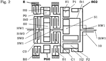
- the second planet gears P2 mesh with the first planetary gears P1 (indicated by the trace 10) and the second ring gear H2, which is fixedly connected to the second ring gear HW1.
- the second planetary gears P2 are wider than the first planetary gears P1.
- the planet gears P1 mesh as in Fig. 1 with the first sun gear S1 and with the first ring gear H1.
- the second ring gear HW1 here is a hollow shaft and the output shaft StW1 facilitates as a solid shaft direct coaxial through drive through the transmission.
- the ranges are indicated by F1 to F4, the slow driving range backwards by Fr. Furthermore, the driving range transitions are 0 (driving speed 0, transition from forward to reverse), with 1 (transition from F1 to F2), with 2 (transition from F2 in F3) and 3 (transition from F3 to F4).
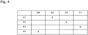
- the second range F2 begins at the switching point 1, when the variator and the sun gear S1 has reached the maximum speed in one direction of rotation, by closing the clutch C0 and opening the brake B1.
- the rotational speed of the internal combustion engine VM is constant and equal to the rotational speed n_S1 of the sun gear S1. Therefore, this transition occurs synchronously, without slip in clutch C0 or brake B1.
- This switching point is another synchronization point in which the speeds n_S1 and n_H1 are the same.
- the speed n_S1 of the sun gear S1 (and thus that of the internal combustion engine VM) is constant in this second range.
- the third area F3 begins in the switching point 3 by releasing the clutch C0 and simultaneously closing the clutch C1, again without slip, in a synchronous point. This will work the contribution of the internal combustion engine VM from the first sun S1 to the first ring gear H1, which now rotates at the constant speed n_H1. At the same time, the rotational speed n_S2 of the second sun gear S2 begins to decrease again until it reaches its maximum in the reverse direction of rotation. The first sun gear S1 runs empty in the entire range at the speed n_S1.
- the fourth range F4 begins in the switching point 3 by releasing the clutch C1 and closing the brake B0, wherein the speed of the variator V and thus the speed n_S2 of the sun gear S2 begins to decrease again.
- the input-side planetary gear PGO comes as a transmission gear to the effect.
- Whose translation is chosen so that the sun in the third area idling with the speed n_S1 S1 in switching point 4 has the appropriate speed of the internal combustion engine VM speed and also clutch C1 and brake B0 can be operated without slippage.
- Switching point 3 is therefore also a synchronization point.
- the speed of the variator V is again varied from a maximum to the maximum in the opposite direction of rotation. Forward
Landscapes
- Engineering & Computer Science (AREA)
- General Engineering & Computer Science (AREA)
- Mechanical Engineering (AREA)
- Transmission Devices (AREA)
- Structure Of Transmissions (AREA)
Abstract
Description
- Die Erfindung betrifft ein stufenloses Leistungsverzweigungsgetriebe für den Antrieb von Fahrzeugen und/oder Arbeitsmaschinen durch eine Verbrennungskraftmaschine, umfassend einen Variator und ein Summierungsgetriebe und eine Anzahl Kupplungen, wobei der Variator einen Teil der Leistung mit zwischen maximalen Drehzahlen in beiden Drehrichtungen kontinuierlich steuerbarer Ausgangsdrehzahl dem Summierungsgetriebe zur Verfügung stellt, die dort dem anderen Teil der Leistung überlagert wird, wobei mehrere Bereiche in Synchronpunkten ineinander überführbar sind, und wobei das Summierungsgetriebe ein 4-welliges Planetengetriebe ist, welches ein erstes Sonnenrad als erstes Zentralrad, ein zweites Zentralrad, ein Hohlrad und ein Anzahl auf einem Steg gelagerte Planetenräder hat.
- Die Patentschrift
DE 35 33 193 hat ein derartiges stufenloses Leistungsverzweigungsgetriebe zum Gegenstand. Sowohl der Variator als auch das Summierungsgetriebe sind koaxial zur Ausgangswelle einer Verbrennungskraftmaschine angeordnet. Der koaxiale Variator erfordert eine Hohlwelle. Das Summierungsgetriebe ist ein Planetengetriebe mit zwei Hohlrädern und steht über zwei weitere Hohlwellen (die eine in der anderen) mit den ausgangsseitig angebrachten Kupplungen in Verbindung. Das Summierungsgetriebe und die Hohlwellen sind sehr aufwendig, insbesondere die äußere der beiden verschachtelten Hohlwellen mit großem Durchmesser. Besonders nachteilig sind die abtriebsseitig angeordneten Kupplungen, die für das Ausgangsmoment des ganzen Getriebes auszulegen sind und daher sehr viel Bauraum brauchen. Schließlich hat das Getriebe nur drei Bereiche, einen rein hydrostatischen und zwei leistungsverzweigte. - Ein weiteres stufenloses Leistungsverzweigungsgetriebe ist in der
US 9,488,263 - Schließlich ist noch aus der
EP 2258966 ein Leistungsverzweigungsgetriebe mit einem hydrostatischen oder elektrischen Variator bekannt, dessen Summierungsgetriebe aus zwei kompletten Planetensätzen (Sonne, Hohlrad und Planetenräder) besteht, deren beider Sonnenräder auf einer vom Variator über Stirnräder angetriebenen Welle sitzen, also fest miteinander verbunden sind; ebenso sind es die Stege (auch Planetenträger genannt) der beiden Planetengetriebe. Der mechanische Leistungspfad umfasst eine Reihe von Stirnradstufen am Getriebeeingang. Daher ist eine Bauweise des Getriebes mit koaxialen Eingangs- und Ausgangswellen nicht möglich und das Getriebe baut sehr breit. Der vorletzte leistungsverzweigte Vorwärtsbereich ist nicht in einem Synchronpunkt in den nächsthöheren Bereich überführbar. - Es ist daher Aufgabe der Erfindung, ein gattungsgemäßes Getriebe zu schaffen, das die eingangs aufgezählten Nachteile vermeidet. Es soll mit weniger und einfacheren Bauteilen eine kostengünstige und Bauraum sparende Bauweise und eine höhere Funktionalität erreicht werden. Dazu dienen die im Kennzeichnungsteil des ersten Anspruchs genannten Merkmale.
- Die in der Eingangseinheit zusammengefassten Kupplungen sind nur für das geringere Eingangsmoment, vor der Endübersetzung und nur für den mechanischen Anteil, auszulegen. Ihr Raumbedarf ist daher reduziert und die Druckölzufuhr ist einfacher.
- Das vierwellige Summierungsgetriebe hat nur einen Planetensatz, zum Unterschied vom erstgenannten Stand der Technik. Ein Getriebeelement (ein Zentralrad, das ist ein Sonnenrad oder ein Hohlrad) entfällt. Das ergibt eine einfachere und kürzere Bauweise des ganzen Getriebes und ermöglicht direkten Durchtrieb, das heißt Eingangswelle und Ausgangswelle des Getriebes liegen auf derselben Drehachse. Trotzdem ist nur eine Hohlwelle nötig.
- Der mechanische Eingangspfad führt je nach Fahrbereich entweder über das erste Sonnenrad oder über das erste Hohlrad. Der Eingangspfad vom Variator führt in jedem Bereich über ein zweites Zentralrad, welches entweder zweites Sonnenrad oder zweites Hohlrad ist. Das ergibt eine größere bauliche Flexibilität im Ausgangsbereich. Der Abtrieb erfolgt jedenfalls über den Steg.
- Die Flexibilität ergibt sich aus der Wahl zwischen zwei Ausführungsformen des Summierungsgetriebes, bei unveränderter Eingangseinheit. In einer ersten Ausführungsform ist das zweite Zentralrad als Sonnenrad ausgebildet. Der Abtrieb erfolgt dann über eine Hohlwelle oder einen ein Abtriebszahnrad aufweisenden Steg. In der zweiten Ausführungsform ist das zweite Zentralrad als Hohlrad ausgebildet und der Abtrieb erfolgt durch eine einfache Vollwelle. Diese Bauweise eignet sich besonders für einen direkten Durchtrieb. Das heißt, Eingangswelle und Ausgangswelle des Getriebes liegen auf derselben Drehachse.
- Der Variator kann sowohl hydrostatisch als auch elektromotorisch oder sonstwie ausgeführt sein, und bezüglich des ganzen Getriebes je nach Einbauerfordernissen angeordnet und mit dem Eingangsglied (Sonnenrad oder Hohlrad) des Summierungsgetriebes antriebsverbunden sein.
- In einer vorteilhaften Ausgestaltung sind das erste Hohlrad und erste Sonnenrad des Summierungsgetriebes auf der Seite der Eingangseinheit und der Steg (=Planetenträger) und das zweite Zentralrad auf der der Eingangseinheit abgewandten Seite des Summierungsgetriebes angeordnet und sind am Steg erste und mit diesen kämmende zweite Planetenräder gelagert. Es handelt sich somit um einen Ravigneaux - Satz. In der ersten Ausführungsform kämmen die zweiten Planetenräder mit dem zweiten Sonnenrad, in der zweiten Ausfürungsform kämmen die zweiten Planetenräder mit dem zweiten Hohlrad. Alles andere ist gleich.
- Weil die Eingangseinheit nur über die ihr zugewandten Elemente des Summierungsgetriebes (das erste Sonnenrad und das erste Hohlrad) mit dem Summierungsgetriebe in Verbindung steht, kann die Eingangseinheit bei unverändertem Summierungsgetriebe verschiedene Ausführungsformen annehmen. In der einfachsten treibt die Eingangswelle von der Verbrennungskraftmaschine direkt wahlweise entweder über eine erste Kupplung das erste Sonnenrad oder über eine zweite Kupplung das erste Hohlrad.
- In einer ersten Weiterbildung ist in der Eingangseinheit eine erste Bremse vorgesehen, mit der das erste Hohlrad festsetzbar ist. Eine Bremse ist auch eine Kupplung und fällt daher im ersten Anspruch unter den Dachbegriff Kupplung. Durch Betätigen nur dieser Bremse (und keiner weiteren Kupplung) wird ein langsamster Bereich mit Antrieb nur über den Variator gewählt. Dabei wirkt das Summierungsgetriebe als Übersetzungsgetriebe mit hoher Übersetzung.
- In einer erweiterten Ausbildung enthält die Eingangseinheit ein als einfaches Planetengetriebes ausgebildetes Übersetzungsgetriebe, das mittels einer eingangsseitigen Bremse schaltbar ist. Damit wird zumindest ein weiterer Bereich geschaffen. In einer bevorzugten Ausbildung besteht das Übersetzungsgetriebe aus einem mit der Eingangswelle fest verbundenen Planetenträger mit eingangsseitigen Planetenrädern, einem eingangsseitigen Sonnenrad auf einer Durchtriebswelle zwischen den Kupplungen und einem eingangsseitigen Hohlrad, das mittels der eingangsseitigen Bremse blockierbar ist. So ist das Übersetzungsgetriebe und die eingangsseitige Bremse raumsparend und mit minimalem Bauaufwand zusammen mit den anderen Kupplungen in der Eingangseinheit zusammengefasst.
- Im Folgenden wird die Erfindung anhand von Abbildungen beschrieben und erläutert. Es stellen dar:
-
Fig. 1 eine erste Ausführungsform im Längsschnitt, vereinfacht, -
Fig. 2 eine zweite Ausführungsform im Längsschnitt, vereinfacht, -
Fig. 3 einen Drehzahlplan zur ersten Ausführungsform, -
Fig. 4 eine Kupplungstabelle zuFig. 3 . - In den
Fig. 1 und2 sind die funktionswesentlichen Elemente mit sinnfälligen Akronymen bezeichnet, der Rest mit Ziffern. Gehäuseteile, Variator und Steuerung sind der Übersichtlichkeit halber weggelassen. Die Akronyme stehen für: - VM
- Verbrennungskraftmaschine
- SG
- stufenloses Leistungsverzweigungsgetriebe
- E
- Eingangseinheit
- SG1
- Summierungsgetriebe in der ersten Ausführungsform
- SG2
- Summierungsgetriebe in der zweiten Ausführungsform
- V
- Variator
- PG0
- eingangsseitiges Planetengetriebe als Übersetzungsgetriebe
- H0
- eingangsseitiges Hohlrad
- H1
- erstes Hohlrad
- H2
- zweites Hohlrad in der zweiten Ausführungsform
- P0
- eingangsseitige Planetenräder
- P1
- erste Planetenräder
- P2
- zweite Planetenräder
- S0
- eingangsseitiges Sonnenrad
- S1
- erstes Sonnenrad
- S2
- zweites Sonnenrad
- St0
- eingangsseitiger Steg (=Planetenträger)
- St1
- erster Steg (=Planetenträger)
- StW0
- Eingangswelle von der VKM
- StW1
- Ausgangswelle
- SW0
- eingangsseitige Sonnenradwelle = Durchtriebswelle
- SW1
- erste Sonnenradwelle
- SW2
- zweite Sonnenradwelle (Zentralradwelle in der ersten Ausführungsform)
- HW1
- erste Hohlradwelle
- HW2
- zweite Hohlradwelle (Zentralradwelle in der zweiten Ausführungsform)
- Z1
- Abtriebszahnrad
- B0
- eingangsseitige Bremse
- B1
- erste Bremse
- C0
- eingangsseitige Kupplung
- C1
- erste Kupplung
- In
Fig. 1 erfolgt der mechanische Kraftfluss von links nach rechts, von der Verbrennungskraftmaschine VM über die Eingangswelle StW0 in die Eingangseinheit E, die sämtliche Kupplungen und Bremsen sowie hier auch ein eingangsseitiges Planetengetriebe PGO enthält. Die Eingangswelle StW0 endet in dem eingangsseitigen Steg St0, der gleichzeitig den Außenteil der beiden Kupplungen C0 und C1 bildet. - Der Innenteil der Kupplung C0 sitzt auf der eingangsseitigen Sonnenradwelle SW0, die in der einfachsten Ausführungsform zugleich die erste Sonnenradwelle SW1 ist und im ersten Sonnenrad S1 des Summierungsgetriebes endet. In der abgebildeten Ausführungsform ist die eingangsseitige Sonnenradwelle (SW0) eine Durchtriebswelle, auf der das eingangsseitige Sonnenrad S0 sitzt, welches Teil des eingangsseitigen Planetengetriebes PGO ist. Dieses wirkt als Übersetzungsgetriebe. Das eingangsseitige Sonnenrad S0 kämmt mit den im eingangsseitigen Steg St0 gelagerten eingangsseitigen Planetenrädern P0, welche ihrerseits mit dem eingangsseitigen Hohlrad H0 kämmen. Das Hohlrad H0 ist mittels der Bremse B0 mit dem Gehäuse der Eingangseinheit E verbindbar und somit blockierbar.
- Der Innenteil der Kupplung C1 sitzt auf der ersten Hohlradwelle HW1, und ist mit dem ersten Hohlrad H1 des Summierungsgetriebes fest verbunden. Je nach gewähltem Bereich wird so der mechanische Leistungsanteil entweder über die Hohlradwelle HW1 oder über die Sonnenradwelle S1 in das Summierungsgetriebe SG eingetragen. Zur Bildung eines rein hydrostischen oder rein elektrischen Bereiches ist die Hohlradwelle HW1 weiters mittels der Bremse B1 mit dem Gehäuse der Eingangseinheit E verbindbar. Das Summierungsgetriebe SG1 wirkt so als reines Übersetzungsgetriebe mit hoher Übersetzung. Das Sonnenrad S1 mit seiner Sonnenradwelle S1 läuft dann leer mit.
- Das Summierungsgetriebe SG1 ist ein vierwelliges Planetengetriebe. Die drei Eingangswellen sind erste Sonnenradwelle SW1 mit dem Sonnenrad S1 und die erste Hohlradwelle HW1 mit dem Hohlrad H1 für den jeweiligen mechanischen Anteil und die Zentralradwelle SW2 (hier die Sonnenradwelle mit dem Sonnenrad S2) für den Anteil vom Variator V. Die Ausgangswelle StW1 ist hier eine die Sonnenradwelle SW2 umgebende Hohlwelle.
- Die Anordnung ist so getroffen, dass das erste Sonnenrad S1 mit den auf dem Steg St1 gelagerten in Axialrichtung verlängerten ersten Planetenrädern P1 kämmt, welch letztere mit dem ersten Hohlrad H1 und mit den auf demselben Steg St1 gelagerten zweiten Planetenrädern P2 kämmen. Dass die beiderlei Planetenräder P1 und P2 miteinander kämmen, ist in der Darstellung durch den Linienzug 10 angedeutet. Der Steg St1 kann in dieser Ausführungsform als Abtriebszahnrad Z1 ausgebildet sein, soferne der Abtrieb nicht über die Abtriebswelle StW1 erfolgt. Das hängt von der Einbaulage des ganzen Getriebes ab.
- Die zweite Ausführungsform gemäß
Fig. 2 unterscheidet sich von der derFig. 1 dadurch, dass als zweites Zentralrad das zweite Sonnenrad S2 durch das auf der zweiten Hohlradwelle SW2 sitzende zweite Hohlrad H2 ersetzt ist. Somit kämmen die zweiten Planetenräder P2 mit den ersten Planetenrädern P1 (durch den Linienzug 10 angedeutet) und mit dem zweiten Hohlrad H2, welches mit der zweiten Hohlradwelle HW1 fest verbunden ist. Wegen der Antriebsverbindung der beiden Hohlräder H1, H2 sind die zweiten Planetenräder P2 breiter als die ersten Planetenräder P1. Die Planetenräder P1 kämmen wie inFig. 1 mit dem ersten Sonnenrad S1 und mit dem ersten Hohlrad H1.Die zweite Hohlradwelle HW1 ist hier eine Hohlwelle und die Ausgangswelle StW1 erleichtert als Vollwelle einen direkten koaxialen Durchtrieb durch das Getriebe. - Anhand des in
Fig. 3 dargestellten Drehzahlplanes der Ausführungsform derFig. 1 und der Kupplungstabelle derFig. 4 wird im Folgenden die Arbeitsweise des Getriebes erläutert. Im Drehzahlplan ist auf der horizontalen Achse die Geschwindigkeit des Fahrzeuges (proportional der Drehzahl des Steges St1) aufgetragen, und auf der vertikalen Achse die Drehzahlen der einzelnen Glieder in Abhängigkeit von der Fahrgeschwindigkeit, und zwar: - Die Drehzahl des Sonnenrades S2, angetrieben vom Variator mit der Drehzahl n_S2, ist lang strichliert,
- die Drehzahl des Sonnenrades S1, angetrieben von der Verbrennungskraftmaschine VM mit der Drehzahl n_S1, ist kurz strichliert,
- die Drehzahl des ersten Hohlrades H1 mit der Drehzahl n_H1, ist punktiert,
- Die Drehzahl des Steges St 1 als Abtriebsdrehzahl n_St1, ist als durchgehende Linie aufgetragen.
- Die Bereiche sind mit F1 bis F4 bezeichnet, der langsame Fahrbereich rückwärts mit Fr. Weiters sind die Fahrbereichsübergänge mit 0 (Fahrgeschwindigkeit 0, Übergang von vorwärts auf rückwärts), mit 1 (Übergang von F1 auf F2), mit 2 (Übergang von F2 in F3) und mit 3 (Übergang von F3 in F4) bezeichnet.
- Im Bereich rückwärts Fr und im ersten Bereich F1 ist gemäß
Fig. 4 die Die Kupplung (=Bremse) B1 geschlossen, das Hohlrad H1 somit festgebremst (n_H1 =0). Der Variator V treibt über das zweite Sonnenrad S2 und dieses über die ersten und zweiten Planetenräder P2 und P1 den Steg St1. Das erste Sonnenrad S1 dreht sich leer (weil die Kupplungen C1 und C2 offen sind) mit der gleichen Drehzahl wie das Sonnenrad S2, aber im umgekehrten Drehsinn. Der Antrieb des Fahrzeuges erfolgt so nur durch den Variator. Rückwärtsfahrt erfolgt in diesem langsamen Bereich einfach durch Umkehrung des Drehsinnes des Variators. Der Bereichsübergang 0 ist kein Schaltpunkt. - Der zweite Bereich F2 beginnt im Schaltpunkt 1, wenn der Variator und auch das Sonnenrad S1 die maximale Drehzahl in einem Drehsinn erreicht hat, durch Schließen der Kupplung C0 und Öffnen der Bremse B1. Die Drehzahl der Verbrennungskraftmaschine VM ist konstant und gleich der Drehzahl n_S1 des Sonnenrades S1. Daher erfolgt dieser Übergang synchron, ohne Schlupf in Kupplung C0 oder Bremse B1. Die Ausgangsdrehzahl n_S2 des Variators V nimmt nun ab, kreuzt die Linie n=0 und nimmt im entgegengesetzten Drehsinn wieder zu, bis der nächste Schaltpunkt 2 erreicht ist. Dieser Schaltpunkt ist ein weiterer Synchronpunkt, in dem die Drehzahlen n_S1 und n_H1 gleich sind. Die Drehzahl n_S1 des Sonnenrades S1 (und damit die der Verbrennungskraftmaschine VM) ist in diesem zweiten Bereich konstant.
- Der dritte Bereich F3 beginnt im Schaltpunkt 3 durch Lösen der Kupplung C0 und simultanes Schließen der Kupplung C1, wieder ohne Schlupf, in einem Synchronpunkt. Dadurch geht der Beitrag der Verbrennungskraftmaschine VM von der ersten Sonne S1 auf das erste Hohlrad H1 über, das nun mit der konstanten Drehzahl n_H1 rotiert. Gleichzeitig beginnt die Drehzahl n_S2 des zweiten Sonnenrades S2 wieder abzunehmen bis sie ihr Maximum im umgekehrten Drehsinn erreicht. Das erste Sonnenrad S1 läuft im ganzen Bereich leer mit der Drehzahl n_S1 um.
- Der vierte Bereich F4 beginnt im Schaltpunkt 3 durch Lösen der Kupplung C1 und Schließen der Bremse B0, wobei die Drehzahl des Variators V und damit die Drehzahl n_S2 des Sonnenrades S2 wieder abzunehmen beginnt. Durch das Schließen der Bremse B0 kommt das eingangsseitige Planetengetriebe PGO als Übersetzungsgetriebe zur Wirkung. Dessen Übersetzung ist so gewählt, dass die im dritten Bereich leer mit der Drehzahl n_S1 mitlaufende Sonne S1 im Schaltpunkt 4 die zur Drehzahl der Verbrennungskraftmaschine VM passende Drehzahl hat und auch hier Kupplung C1 und Bremse B0 ohne Schlupf betätigt werden können. Schaltpunkt 3 ist somit auch ein Synchronpunkt. In diesem vierten Bereich wird die Drehzahl des Variators V wieder von einem Maximum bis zu dem Maximum mit entgegengesetztem Drehsinn variiert. Vorwärts
- Insgesamt ist so ein Getriebe mit einem Bereich rückwärts und vier Bereichen vorwärts geschaffen, die jeweils synchron ineinander übergehen.
Claims (11)
- Stufenloses Leistungsverzweigungsgetriebe für den Antrieb von Fahrzeugen und/oder Arbeitsmaschinen durch eine Verbrennungskraftmaschine, umfassend einen Variator und ein Summierungsgetriebe und eine Anzahl Kupplungen, wobei der Variator einen Teil der Leistung mit zwischen maximalen Drehzahlen in beiden Drehrichtungen kontinuierlich steuerbarer Ausgangsdrehzahl dem Summierungsgetriebe zur Verfügung stellt, die dort dem anderen Teil der Leistung überlagert wird, wobei mehrere Bereiche in Synchronpunkten ineinander überführbar sind, und wobei das Summierungsgetriebe ein 4-welliges Planetengetriebe ist, welches ein erstes Sonnenrad (S1) als erstes Zentralrad, ein zweites Zentralrad (S2; H2), ein Hohlrad (H1) und ein Anzahl auf einem Steg (St1) gelagerte Planetenräder (P1,P2) hat, dadurch gekennzeichnet, dassa. die Kupplungen (C0, C1; B0, B1) in einer Eingangseinheit (E) zusammengefast sind, die im Kraftfluss zwischen der Verbrennungskraftmaschine(V) und dem Summierungsgetriebe (SG1; SG2) angeordnet ist,b. das Summierungsgetriebe (SG1; SG2) als Planetenräder miteinander kämmende erste (P1) und zweite (P2) auf einem gemeinsamen Planetenträger (St1) gelagerte Planetenräder (P1, P2) hat,c. das erste Sonnenrad (S1) oder das erste Hohlrad (H1) von der Verbrennungskraftmaschine (V) und das zweite Zentralrad (S2; H2) vom Variator (V) angetrieben ist, wobei das erste Sonnenrad (S1) oder das erste Hohlrad (H1) beim Übergang von einem Bereich den nächsten in einem Synchronpunkt abwechselnd über die Eingangseinheit (E) mit der Verbrennungskraftmaschine (V) antriebsverbunden sind,d. und wobei schließlich der Steg (St1) mit der zu treibenden Last (Fahrzeug) verbunden ist.
- Verzweigungsgetriebe [Fig. 1] nach Anspruch 1, dadurch gekennzeichnet, dass das zweite Zentralrad als zweites Sonnenrad (S2) ausgebildet ist.
- Verzweigungsgetriebe nach Anspruch 2, dadurch gekennzeichnet, dass der Steg (St1) ein Abtriebzahnrad (Z1) bildet oder mit einem solchen (Z1) drehfest verbunden ist.
- Verzweigungsgetriebe [Fig. 2] nach Anspruch 1, dadurch gekennzeichnet, dass das zweite Zentralrad als zweites Hohlrad (H2) ausgebildet ist.
- Verzweigungsgetriebe nach einem der vorherigen Ansprüche, dadurch gekennzeichnet, dass das erste Hohlrad (H1) auf der Seite der Eingangseinheit (E) und der Steg (St1) auf der der Eingangseinheit (E) abgewandten Seite des Summierungsgetriebes (SG1; SG2) angeordnet ist, und dass das erste Sonnenrad (S1) auf der der Eingangseinheit (E) zugewandten Seite und das zweite Zentralrad (S2; H2) auf der der Eingangseinheit (E) abgewandten Seite angeordnet sind, und dass der Steg (St1) auf der der Eingangseinheit (E) abgewandten Seite angeordnet und das Ausgangselement ist, das mit der summierten kontinuierlich variablen Drehzahl rotiert.
- Verzweigungsgetriebe nach Anspruch 2 [Fig. 1], dadurch gekennzeichnet, dass das erste Sonnenrad (S1) mit den ersten Planetenrädern (P1), das zweite Sonnenrad (S2) mit den zweiten Planetenrädern (P2), die Zweiten Planetenräder (P2) mit den ersten Planetenrädern (P1) und das erste Planetenrad (P1) mit dem ersten Hohlrad (H1) kämmen.
- Verzweigungsgetriebe nach Anspruch 4 [Fig. 2], dadurch gekennzeichnet, dass das erste Sonnenrad (S1) mit den ersten Planetenrädern (P1), das erste Hohlrad (H1) mit den ersten Planetenrädern (P1), die ersten Planetenräder (P1) mit den zweiten Planetenrädern (P2) und die zweiten Planetenräder (P2) mit dem zweiten Hohlrad (H2) kämmen.
- Verzweigungsgetriebe nach einem der vorhergehenden Ansprüche, dadurch gekennzeichnet, dass die Eingangseinheit (E) über eine Eingangswelle (StW0) mit der Verbrennungskraftmaschine (VM) antriebsverbunden ist und eine erste Kupplung (C0) und eine zweite Kupplung (C1) enthält, wobei die erste Kupplung (C0) die Verbindung zwischen der Eingangswelle (StW0) und einer im ersten Sonnenrad (S1) endenden Sonnenradwelle (SW1) herstellt, und wobei die zweite Kupplung (C1) die Eingangswelle (StW0) mit der ersten Hohlradwelle (HW1) verbindet.
- Verzweigungsgetriebe nach Anspruch 8, dadurch gekennzeichnet, dass die Eingangseinheit (E) eine Bremse (B1) enthält, mittels derer das erste Hohlrad (H1) blockierbar ist.
- Verzweigungsgetriebe nach Anspruch 8, dadurch gekennzeichnet, dass die Eingangseinheit (E) ein als einfaches Planetengetriebes ausgebildetes Übersetzungsgetriebe (PG0) enthält, das mittels einer eingangsseitigen Bremse (B0) schaltbar ist.
- Verzweigungsgetriebe nach Anspruch 10, dadurch gekennzeichnet, dass das Übersetzungsgetriebe besteht: aus einem mit der Eingangswelle (StW0) fest verbundenen eingangsseitigen Planetenträger (St0), auf dem eingangsseitige Planetenräder (P0) gelagert sind; aus einem eingangsseitigen Sonnenrad (S0), das auf der eingangsseitigen Sonnenradwelle (SW0, SW1) sitzt und zwischen den Kupplungen (C0, C1) angeordnet ist; und aus einem eingangsseitigen Hohlrad (H0), das mittels der eingangsseitigen Bremse (B2) blockierbar ist.
Priority Applications (7)
| Application Number | Priority Date | Filing Date | Title |
|---|---|---|---|
| EP18000267.7A EP3543560B1 (de) | 2018-03-19 | 2018-03-19 | Stufenloses verzweigungsgetriebe |
| PL18000267T PL3543560T3 (pl) | 2018-03-19 | 2018-03-19 | Bezstopniowa przekładnia z rozdziałem mocy |
| RU2019107513A RU2769436C2 (ru) | 2018-03-19 | 2019-03-15 | Бесступенчатая раздаточная коробка |
| JP2019049352A JP2019215075A (ja) | 2018-03-19 | 2019-03-18 | 連続無段式動力分割伝動装置 |
| CN201910204278.3A CN110285199A (zh) | 2018-03-19 | 2019-03-18 | 功率分流无级变速传动系统 |
| US16/355,911 US10794458B2 (en) | 2018-03-19 | 2019-03-18 | Continuously variable power split transmission |
| JP2023217123A JP2024038055A (ja) | 2018-03-19 | 2023-12-22 | 連続無段式動力分割伝動装置 |
Applications Claiming Priority (1)
| Application Number | Priority Date | Filing Date | Title |
|---|---|---|---|
| EP18000267.7A EP3543560B1 (de) | 2018-03-19 | 2018-03-19 | Stufenloses verzweigungsgetriebe |
Publications (2)
| Publication Number | Publication Date |
|---|---|
| EP3543560A1 true EP3543560A1 (de) | 2019-09-25 |
| EP3543560B1 EP3543560B1 (de) | 2020-11-25 |
Family
ID=61731580
Family Applications (1)
| Application Number | Title | Priority Date | Filing Date |
|---|---|---|---|
| EP18000267.7A Active EP3543560B1 (de) | 2018-03-19 | 2018-03-19 | Stufenloses verzweigungsgetriebe |
Country Status (6)
| Country | Link |
|---|---|
| US (1) | US10794458B2 (de) |
| EP (1) | EP3543560B1 (de) |
| JP (2) | JP2019215075A (de) |
| CN (1) | CN110285199A (de) |
| PL (1) | PL3543560T3 (de) |
| RU (1) | RU2769436C2 (de) |
Citations (5)
| Publication number | Priority date | Publication date | Assignee | Title |
|---|---|---|---|---|
| DE2757300A1 (de) * | 1977-12-22 | 1979-06-28 | Zahnradfabrik Friedrichshafen | Stufenlos einstellbares hydrostatisch- mechanisches verbundgetriebe |
| DE3536335A1 (de) * | 1985-10-11 | 1987-04-16 | Michael Meyerle | Stufenloses hydromechanisches verzweigungsgetriebe fuer kraftfahrzeuge |
| DE3533193A1 (de) | 1985-09-18 | 1987-05-07 | Michael Meyerle | Stufenloses hydromechanisches verzweigungsgetriebe fuer kraftfahrzeuge |
| EP2258966A1 (de) | 2009-06-04 | 2010-12-08 | Dieter Stöckl | Überlagerungsgetriebe |
| US9488263B2 (en) | 2014-08-15 | 2016-11-08 | Caterpillar Inc. | Modular arrangement for hydromechanical transmission |
Family Cites Families (15)
| Publication number | Priority date | Publication date | Assignee | Title |
|---|---|---|---|---|
| DE2758659C3 (de) * | 1977-12-29 | 1982-03-18 | Zahnradfabrik Friedrichshafen Ag, 7990 Friedrichshafen | Hydrostatisch-mechanisches Getriebe mit Leistungsverzweigung |
| DE3125123C2 (de) * | 1981-06-26 | 1987-01-08 | Zahnradfabrik Friedrichshafen Ag, 7990 Friedrichshafen | Getriebe für ein frontgetriebenes Fahrzeug |
| DE3709191A1 (de) * | 1986-04-10 | 1988-05-11 | Michael Meyerle | Stufenloses verzweigungsgetriebe insbesondere fuer kraftfahrzeuge |
| US4856371A (en) * | 1987-03-12 | 1989-08-15 | Tractiontec Corporation | Traction drive transmission system |
| JP2671463B2 (ja) * | 1988-12-07 | 1997-10-29 | トヨタ自動車株式会社 | 自動変速機用歯車変速装置 |
| US5931758A (en) * | 1998-04-08 | 1999-08-03 | General Dynamics Land Systems, Inc. | Simplified multi-range hydromechanical transmission for vehicles |
| RU2192572C1 (ru) * | 2001-08-17 | 2002-11-10 | Коротков Эдуард Константинович | Универсальная голономная передача с бесступенчатым изменением крутящего момента (варианты) |
| US7011600B2 (en) * | 2003-02-28 | 2006-03-14 | Fallbrook Technologies Inc. | Continuously variable transmission |
| RU2292270C2 (ru) * | 2004-01-28 | 2007-01-27 | Снимщиков Вячеслав Константинович | Активная трансмиссия, коробка прямого включения (механическая), коробка скоростей с планетарным фрикционом и независимой задней передачей, раздаточная коробка с механизмом распределения крутящего момента осями (колесами) |
| US8251848B2 (en) * | 2006-08-03 | 2012-08-28 | Toyota Jidosha Kabushiki Kaisha | Power split dual input shaft transmission for vehicle |
| DE102008027074A1 (de) * | 2007-06-21 | 2008-12-24 | Luk Lamellen Und Kupplungsbau Beteiligungs Kg | Leistungsverzweigtes, stufenloses Fahrzeuggetriebe |
| BR112015015749A2 (pt) * | 2012-12-28 | 2017-07-11 | Liu Guangquan | transmissão de variação contínua, e, veículo |
| JP2013064511A (ja) * | 2013-01-06 | 2013-04-11 | Hideki Matsumura | 歯車式無段変速機構 |
| DE102014204009A1 (de) * | 2014-03-05 | 2015-09-10 | Schaeffler Technologies AG & Co. KG | Mehrgängiges Planetengetriebesystem als Komponente des Antriebsstrangs eines Kraftfahrzeuges |
| DE102016200644B4 (de) * | 2016-01-19 | 2017-10-19 | Bayerische Motoren Werke Aktiengesellschaft | Kompaktes Mehrstufengetriebe |
-
2018
- 2018-03-19 PL PL18000267T patent/PL3543560T3/pl unknown
- 2018-03-19 EP EP18000267.7A patent/EP3543560B1/de active Active
-
2019
- 2019-03-15 RU RU2019107513A patent/RU2769436C2/ru active
- 2019-03-18 US US16/355,911 patent/US10794458B2/en active Active
- 2019-03-18 JP JP2019049352A patent/JP2019215075A/ja active Pending
- 2019-03-18 CN CN201910204278.3A patent/CN110285199A/zh active Pending
-
2023
- 2023-12-22 JP JP2023217123A patent/JP2024038055A/ja not_active Withdrawn
Patent Citations (5)
| Publication number | Priority date | Publication date | Assignee | Title |
|---|---|---|---|---|
| DE2757300A1 (de) * | 1977-12-22 | 1979-06-28 | Zahnradfabrik Friedrichshafen | Stufenlos einstellbares hydrostatisch- mechanisches verbundgetriebe |
| DE3533193A1 (de) | 1985-09-18 | 1987-05-07 | Michael Meyerle | Stufenloses hydromechanisches verzweigungsgetriebe fuer kraftfahrzeuge |
| DE3536335A1 (de) * | 1985-10-11 | 1987-04-16 | Michael Meyerle | Stufenloses hydromechanisches verzweigungsgetriebe fuer kraftfahrzeuge |
| EP2258966A1 (de) | 2009-06-04 | 2010-12-08 | Dieter Stöckl | Überlagerungsgetriebe |
| US9488263B2 (en) | 2014-08-15 | 2016-11-08 | Caterpillar Inc. | Modular arrangement for hydromechanical transmission |
Also Published As
| Publication number | Publication date |
|---|---|
| JP2019215075A (ja) | 2019-12-19 |
| RU2019107513A (ru) | 2020-09-15 |
| RU2019107513A3 (de) | 2022-02-28 |
| JP2024038055A (ja) | 2024-03-19 |
| RU2769436C2 (ru) | 2022-03-31 |
| US10794458B2 (en) | 2020-10-06 |
| EP3543560B1 (de) | 2020-11-25 |
| US20200325969A9 (en) | 2020-10-15 |
| CN110285199A (zh) | 2019-09-27 |
| US20190285154A1 (en) | 2019-09-19 |
| PL3543560T3 (pl) | 2021-06-14 |
Similar Documents
| Publication | Publication Date | Title |
|---|---|---|
| EP0195452B1 (de) | Stufenlos einstellbares, leistungsverzweigendes Verbund-Lastschaltgetriebe mit Gruppenschaltungen | |
| EP1611373B1 (de) | Getriebe, insbesondere automatisiertes leistungsverzweigtes mehrganggetriebe | |
| EP1611370B1 (de) | Mehrstufen-automatgetriebe | |
| DE102007028883B4 (de) | Getriebebaueinheit, insbesondere Mehrbereichsgetriebe | |
| DE10249485A1 (de) | Leistungsverzweigtes Getriebe | |
| DE102010039865A1 (de) | Mehrstufengetriebe | |
| AT521773B1 (de) | Antriebsstrang für ein Kraftfahrzeug | |
| EP1055835B1 (de) | Schalt-Zahnkupplung | |
| DE102017219111B4 (de) | Leistungsverzweigte stufenlose Getriebevorrichtung | |
| DE102014223213A1 (de) | Bereichsgetriebe und Verfahren zum Betreiben eines Bereichsgetriebes | |
| DE102008027074A1 (de) | Leistungsverzweigtes, stufenloses Fahrzeuggetriebe | |
| DE102007017573A1 (de) | Getriebeeinheit, insbesondere Mehrbereichsgetriebe | |
| DE102020202416B3 (de) | Leistungsverzweigtes stufenloses Getriebe | |
| EP3543560B1 (de) | Stufenloses verzweigungsgetriebe | |
| DE102005022012A1 (de) | Getriebe für ein Kraftfahrzeug mit stufenlosen leistungsverzweigten Fahrbereichen | |
| DE102020202287B3 (de) | Leistungsverzweigtes stufenloses Getriebe | |
| DE102020201778B4 (de) | Leistungsverzweigtes stufenloses Getriebe | |
| DE102020201690B3 (de) | Leistungsverzweigtes stufenloses Getriebe | |
| DE102020200999B3 (de) | Leistungsverzweigtes stufenloses Getriebe | |
| DE102020202286B3 (de) | Leistungsverzweigtes stufenloses Getriebe | |
| DE102020202417B3 (de) | Leistungsverzweigtes stufenloses Getriebe | |
| DE102020201004B3 (de) | Leistungsverzweigtes stufenloses Getriebe | |
| AT500431B1 (de) | Hydrostatisch-mechanisches leistungsverzweigungsgetriebe mit grosser spreizung | |
| DE102020202415B4 (de) | Leistungsverzweigtes stufenloses Getriebe | |
| DE102020202000B4 (de) | Leistungsverzweigtes stufenloses Getriebe |
Legal Events
| Date | Code | Title | Description |
|---|---|---|---|
| PUAI | Public reference made under article 153(3) epc to a published international application that has entered the european phase |
Free format text: ORIGINAL CODE: 0009012 |
|
| STAA | Information on the status of an ep patent application or granted ep patent |
Free format text: STATUS: REQUEST FOR EXAMINATION WAS MADE |
|
| 17P | Request for examination filed |
Effective date: 20190131 |
|
| AK | Designated contracting states |
Kind code of ref document: A1 Designated state(s): AL AT BE BG CH CY CZ DE DK EE ES FI FR GB GR HR HU IE IS IT LI LT LU LV MC MK MT NL NO PL PT RO RS SE SI SK SM TR |
|
| AX | Request for extension of the european patent |
Extension state: BA ME |
|
| RIC1 | Information provided on ipc code assigned before grant |
Ipc: F16H 37/08 20060101AFI20200423BHEP Ipc: F16H 47/04 20060101ALN20200423BHEP |
|
| RIC1 | Information provided on ipc code assigned before grant |
Ipc: F16H 47/04 20060101ALN20200427BHEP Ipc: F16H 37/08 20060101AFI20200427BHEP |
|
| GRAP | Despatch of communication of intention to grant a patent |
Free format text: ORIGINAL CODE: EPIDOSNIGR1 |
|
| STAA | Information on the status of an ep patent application or granted ep patent |
Free format text: STATUS: GRANT OF PATENT IS INTENDED |
|
| RIC1 | Information provided on ipc code assigned before grant |
Ipc: F16H 37/08 20060101AFI20200504BHEP Ipc: F16H 47/04 20060101ALN20200504BHEP |
|
| GRAJ | Information related to disapproval of communication of intention to grant by the applicant or resumption of examination proceedings by the epo deleted |
Free format text: ORIGINAL CODE: EPIDOSDIGR1 |
|
| STAA | Information on the status of an ep patent application or granted ep patent |
Free format text: STATUS: REQUEST FOR EXAMINATION WAS MADE |
|
| INTG | Intention to grant announced |
Effective date: 20200605 |
|
| GRAP | Despatch of communication of intention to grant a patent |
Free format text: ORIGINAL CODE: EPIDOSNIGR1 |
|
| STAA | Information on the status of an ep patent application or granted ep patent |
Free format text: STATUS: GRANT OF PATENT IS INTENDED |
|
| INTC | Intention to grant announced (deleted) | ||
| RIC1 | Information provided on ipc code assigned before grant |
Ipc: F16H 47/04 20060101ALN20200629BHEP Ipc: F16H 37/08 20060101AFI20200629BHEP |
|
| GRAS | Grant fee paid |
Free format text: ORIGINAL CODE: EPIDOSNIGR3 |
|
| INTG | Intention to grant announced |
Effective date: 20200723 |
|
| GRAJ | Information related to disapproval of communication of intention to grant by the applicant or resumption of examination proceedings by the epo deleted |
Free format text: ORIGINAL CODE: EPIDOSDIGR1 |
|
| GRAL | Information related to payment of fee for publishing/printing deleted |
Free format text: ORIGINAL CODE: EPIDOSDIGR3 |
|
| STAA | Information on the status of an ep patent application or granted ep patent |
Free format text: STATUS: REQUEST FOR EXAMINATION WAS MADE |
|
| INTC | Intention to grant announced (deleted) | ||
| GRAP | Despatch of communication of intention to grant a patent |
Free format text: ORIGINAL CODE: EPIDOSNIGR1 |
|
| STAA | Information on the status of an ep patent application or granted ep patent |
Free format text: STATUS: GRANT OF PATENT IS INTENDED |
|
| RIC1 | Information provided on ipc code assigned before grant |
Ipc: F16H 47/04 20060101ALN20200903BHEP Ipc: F16H 37/08 20060101AFI20200903BHEP |
|
| GRAA | (expected) grant |
Free format text: ORIGINAL CODE: 0009210 |
|
| STAA | Information on the status of an ep patent application or granted ep patent |
Free format text: STATUS: THE PATENT HAS BEEN GRANTED |
|
| INTG | Intention to grant announced |
Effective date: 20201006 |
|
| AK | Designated contracting states |
Kind code of ref document: B1 Designated state(s): AL AT BE BG CH CY CZ DE DK EE ES FI FR GB GR HR HU IE IS IT LI LT LU LV MC MK MT NL NO PL PT RO RS SE SI SK SM TR |
|
| REG | Reference to a national code |
Ref country code: GB Ref legal event code: FG4D Free format text: NOT ENGLISH |
|
| REG | Reference to a national code |
Ref country code: CH Ref legal event code: EP |
|
| REG | Reference to a national code |
Ref country code: AT Ref legal event code: REF Ref document number: 1338702 Country of ref document: AT Kind code of ref document: T Effective date: 20201215 |
|
| REG | Reference to a national code |
Ref country code: DE Ref legal event code: R096 Ref document number: 502018003071 Country of ref document: DE |
|
| REG | Reference to a national code |
Ref country code: IE Ref legal event code: FG4D Free format text: LANGUAGE OF EP DOCUMENT: GERMAN |
|
| REG | Reference to a national code |
Ref country code: NL Ref legal event code: MP Effective date: 20201125 |
|
| PG25 | Lapsed in a contracting state [announced via postgrant information from national office to epo] |
Ref country code: FI Free format text: LAPSE BECAUSE OF FAILURE TO SUBMIT A TRANSLATION OF THE DESCRIPTION OR TO PAY THE FEE WITHIN THE PRESCRIBED TIME-LIMIT Effective date: 20201125 Ref country code: RS Free format text: LAPSE BECAUSE OF FAILURE TO SUBMIT A TRANSLATION OF THE DESCRIPTION OR TO PAY THE FEE WITHIN THE PRESCRIBED TIME-LIMIT Effective date: 20201125 Ref country code: PT Free format text: LAPSE BECAUSE OF FAILURE TO SUBMIT A TRANSLATION OF THE DESCRIPTION OR TO PAY THE FEE WITHIN THE PRESCRIBED TIME-LIMIT Effective date: 20210325 Ref country code: NO Free format text: LAPSE BECAUSE OF FAILURE TO SUBMIT A TRANSLATION OF THE DESCRIPTION OR TO PAY THE FEE WITHIN THE PRESCRIBED TIME-LIMIT Effective date: 20210225 Ref country code: GR Free format text: LAPSE BECAUSE OF FAILURE TO SUBMIT A TRANSLATION OF THE DESCRIPTION OR TO PAY THE FEE WITHIN THE PRESCRIBED TIME-LIMIT Effective date: 20210226 |
|
| PG25 | Lapsed in a contracting state [announced via postgrant information from national office to epo] |
Ref country code: SE Free format text: LAPSE BECAUSE OF FAILURE TO SUBMIT A TRANSLATION OF THE DESCRIPTION OR TO PAY THE FEE WITHIN THE PRESCRIBED TIME-LIMIT Effective date: 20201125 Ref country code: IS Free format text: LAPSE BECAUSE OF FAILURE TO SUBMIT A TRANSLATION OF THE DESCRIPTION OR TO PAY THE FEE WITHIN THE PRESCRIBED TIME-LIMIT Effective date: 20210325 Ref country code: LV Free format text: LAPSE BECAUSE OF FAILURE TO SUBMIT A TRANSLATION OF THE DESCRIPTION OR TO PAY THE FEE WITHIN THE PRESCRIBED TIME-LIMIT Effective date: 20201125 Ref country code: BG Free format text: LAPSE BECAUSE OF FAILURE TO SUBMIT A TRANSLATION OF THE DESCRIPTION OR TO PAY THE FEE WITHIN THE PRESCRIBED TIME-LIMIT Effective date: 20210225 |
|
| REG | Reference to a national code |
Ref country code: LT Ref legal event code: MG9D |
|
| PG25 | Lapsed in a contracting state [announced via postgrant information from national office to epo] |
Ref country code: HR Free format text: LAPSE BECAUSE OF FAILURE TO SUBMIT A TRANSLATION OF THE DESCRIPTION OR TO PAY THE FEE WITHIN THE PRESCRIBED TIME-LIMIT Effective date: 20201125 |
|
| PG25 | Lapsed in a contracting state [announced via postgrant information from national office to epo] |
Ref country code: RO Free format text: LAPSE BECAUSE OF FAILURE TO SUBMIT A TRANSLATION OF THE DESCRIPTION OR TO PAY THE FEE WITHIN THE PRESCRIBED TIME-LIMIT Effective date: 20201125 Ref country code: SK Free format text: LAPSE BECAUSE OF FAILURE TO SUBMIT A TRANSLATION OF THE DESCRIPTION OR TO PAY THE FEE WITHIN THE PRESCRIBED TIME-LIMIT Effective date: 20201125 Ref country code: CZ Free format text: LAPSE BECAUSE OF FAILURE TO SUBMIT A TRANSLATION OF THE DESCRIPTION OR TO PAY THE FEE WITHIN THE PRESCRIBED TIME-LIMIT Effective date: 20201125 Ref country code: EE Free format text: LAPSE BECAUSE OF FAILURE TO SUBMIT A TRANSLATION OF THE DESCRIPTION OR TO PAY THE FEE WITHIN THE PRESCRIBED TIME-LIMIT Effective date: 20201125 Ref country code: LT Free format text: LAPSE BECAUSE OF FAILURE TO SUBMIT A TRANSLATION OF THE DESCRIPTION OR TO PAY THE FEE WITHIN THE PRESCRIBED TIME-LIMIT Effective date: 20201125 Ref country code: SM Free format text: LAPSE BECAUSE OF FAILURE TO SUBMIT A TRANSLATION OF THE DESCRIPTION OR TO PAY THE FEE WITHIN THE PRESCRIBED TIME-LIMIT Effective date: 20201125 |
|
| REG | Reference to a national code |
Ref country code: DE Ref legal event code: R097 Ref document number: 502018003071 Country of ref document: DE |
|
| PG25 | Lapsed in a contracting state [announced via postgrant information from national office to epo] |
Ref country code: DK Free format text: LAPSE BECAUSE OF FAILURE TO SUBMIT A TRANSLATION OF THE DESCRIPTION OR TO PAY THE FEE WITHIN THE PRESCRIBED TIME-LIMIT Effective date: 20201125 |
|
| PLBE | No opposition filed within time limit |
Free format text: ORIGINAL CODE: 0009261 |
|
| STAA | Information on the status of an ep patent application or granted ep patent |
Free format text: STATUS: NO OPPOSITION FILED WITHIN TIME LIMIT |
|
| PG25 | Lapsed in a contracting state [announced via postgrant information from national office to epo] |
Ref country code: MC Free format text: LAPSE BECAUSE OF FAILURE TO SUBMIT A TRANSLATION OF THE DESCRIPTION OR TO PAY THE FEE WITHIN THE PRESCRIBED TIME-LIMIT Effective date: 20201125 Ref country code: NL Free format text: LAPSE BECAUSE OF FAILURE TO SUBMIT A TRANSLATION OF THE DESCRIPTION OR TO PAY THE FEE WITHIN THE PRESCRIBED TIME-LIMIT Effective date: 20201125 Ref country code: AL Free format text: LAPSE BECAUSE OF FAILURE TO SUBMIT A TRANSLATION OF THE DESCRIPTION OR TO PAY THE FEE WITHIN THE PRESCRIBED TIME-LIMIT Effective date: 20201125 |
|
| REG | Reference to a national code |
Ref country code: CH Ref legal event code: PL |
|
| 26N | No opposition filed |
Effective date: 20210826 |
|
| PG25 | Lapsed in a contracting state [announced via postgrant information from national office to epo] |
Ref country code: SI Free format text: LAPSE BECAUSE OF FAILURE TO SUBMIT A TRANSLATION OF THE DESCRIPTION OR TO PAY THE FEE WITHIN THE PRESCRIBED TIME-LIMIT Effective date: 20201125 |
|
| REG | Reference to a national code |
Ref country code: BE Ref legal event code: MM Effective date: 20210331 |
|
| PG25 | Lapsed in a contracting state [announced via postgrant information from national office to epo] |
Ref country code: ES Free format text: LAPSE BECAUSE OF FAILURE TO SUBMIT A TRANSLATION OF THE DESCRIPTION OR TO PAY THE FEE WITHIN THE PRESCRIBED TIME-LIMIT Effective date: 20201125 Ref country code: IE Free format text: LAPSE BECAUSE OF NON-PAYMENT OF DUE FEES Effective date: 20210319 Ref country code: CH Free format text: LAPSE BECAUSE OF NON-PAYMENT OF DUE FEES Effective date: 20210331 Ref country code: LI Free format text: LAPSE BECAUSE OF NON-PAYMENT OF DUE FEES Effective date: 20210331 Ref country code: LU Free format text: LAPSE BECAUSE OF NON-PAYMENT OF DUE FEES Effective date: 20210319 |
|
| PG25 | Lapsed in a contracting state [announced via postgrant information from national office to epo] |
Ref country code: IS Free format text: LAPSE BECAUSE OF FAILURE TO SUBMIT A TRANSLATION OF THE DESCRIPTION OR TO PAY THE FEE WITHIN THE PRESCRIBED TIME-LIMIT Effective date: 20210325 |
|
| PG25 | Lapsed in a contracting state [announced via postgrant information from national office to epo] |
Ref country code: BE Free format text: LAPSE BECAUSE OF NON-PAYMENT OF DUE FEES Effective date: 20210331 |
|
| GBPC | Gb: european patent ceased through non-payment of renewal fee |
Effective date: 20220319 |
|
| PG25 | Lapsed in a contracting state [announced via postgrant information from national office to epo] |
Ref country code: GB Free format text: LAPSE BECAUSE OF NON-PAYMENT OF DUE FEES Effective date: 20220319 |
|
| PG25 | Lapsed in a contracting state [announced via postgrant information from national office to epo] |
Ref country code: CY Free format text: LAPSE BECAUSE OF FAILURE TO SUBMIT A TRANSLATION OF THE DESCRIPTION OR TO PAY THE FEE WITHIN THE PRESCRIBED TIME-LIMIT Effective date: 20201125 |
|
| PG25 | Lapsed in a contracting state [announced via postgrant information from national office to epo] |
Ref country code: HU Free format text: LAPSE BECAUSE OF FAILURE TO SUBMIT A TRANSLATION OF THE DESCRIPTION OR TO PAY THE FEE WITHIN THE PRESCRIBED TIME-LIMIT; INVALID AB INITIO Effective date: 20180319 |
|
| PG25 | Lapsed in a contracting state [announced via postgrant information from national office to epo] |
Ref country code: MK Free format text: LAPSE BECAUSE OF FAILURE TO SUBMIT A TRANSLATION OF THE DESCRIPTION OR TO PAY THE FEE WITHIN THE PRESCRIBED TIME-LIMIT Effective date: 20201125 |
|
| REG | Reference to a national code |
Ref country code: AT Ref legal event code: MM01 Ref document number: 1338702 Country of ref document: AT Kind code of ref document: T Effective date: 20230319 |
|
| PGFP | Annual fee paid to national office [announced via postgrant information from national office to epo] |
Ref country code: PL Payment date: 20240306 Year of fee payment: 7 Ref country code: FR Payment date: 20240326 Year of fee payment: 7 |
|
| PG25 | Lapsed in a contracting state [announced via postgrant information from national office to epo] |
Ref country code: AT Free format text: LAPSE BECAUSE OF NON-PAYMENT OF DUE FEES Effective date: 20230319 |
|
| PG25 | Lapsed in a contracting state [announced via postgrant information from national office to epo] |
Ref country code: AT Free format text: LAPSE BECAUSE OF NON-PAYMENT OF DUE FEES Effective date: 20230319 |
|
| PG25 | Lapsed in a contracting state [announced via postgrant information from national office to epo] |
Ref country code: MT Free format text: LAPSE BECAUSE OF FAILURE TO SUBMIT A TRANSLATION OF THE DESCRIPTION OR TO PAY THE FEE WITHIN THE PRESCRIBED TIME-LIMIT Effective date: 20201125 |
|
| PG25 | Lapsed in a contracting state [announced via postgrant information from national office to epo] |
Ref country code: TR Free format text: LAPSE BECAUSE OF FAILURE TO SUBMIT A TRANSLATION OF THE DESCRIPTION OR TO PAY THE FEE WITHIN THE PRESCRIBED TIME-LIMIT Effective date: 20201125 |
|
| PG25 | Lapsed in a contracting state [announced via postgrant information from national office to epo] |
Ref country code: FR Free format text: LAPSE BECAUSE OF NON-PAYMENT OF DUE FEES Effective date: 20250331 |
|
| PGFP | Annual fee paid to national office [announced via postgrant information from national office to epo] |
Ref country code: DE Payment date: 20260320 Year of fee payment: 9 |
|
| PGFP | Annual fee paid to national office [announced via postgrant information from national office to epo] |
Ref country code: AT Payment date: 20260410 Year of fee payment: 5 |
|
| PGFP | Annual fee paid to national office [announced via postgrant information from national office to epo] |
Ref country code: IT Payment date: 20260220 Year of fee payment: 9 |
|
| PG25 | Lapsed in a contracting state [announced via postgrant information from national office to epo] |
Ref country code: PL Free format text: LAPSE BECAUSE OF NON-PAYMENT OF DUE FEES Effective date: 20250319 |