EP3543086A1 - Procédé pour prédire un changement dans la direction de déplacement d'un véhicule - Google Patents
Procédé pour prédire un changement dans la direction de déplacement d'un véhicule Download PDFInfo
- Publication number
- EP3543086A1 EP3543086A1 EP18163369.4A EP18163369A EP3543086A1 EP 3543086 A1 EP3543086 A1 EP 3543086A1 EP 18163369 A EP18163369 A EP 18163369A EP 3543086 A1 EP3543086 A1 EP 3543086A1
- Authority
- EP
- European Patent Office
- Prior art keywords
- vehicle
- wheel
- change
- travel
- wheel angle
- Prior art date
- Legal status (The legal status is an assumption and is not a legal conclusion. Google has not performed a legal analysis and makes no representation as to the accuracy of the status listed.)
- Withdrawn
Links
- 230000008859 change Effects 0.000 title claims abstract description 56
- 238000000034 method Methods 0.000 title claims abstract description 41
- 238000012549 training Methods 0.000 claims abstract description 8
- 238000013527 convolutional neural network Methods 0.000 claims description 8
- 238000004891 communication Methods 0.000 claims description 3
- 230000015654 memory Effects 0.000 description 17
- 238000012545 processing Methods 0.000 description 15
- 238000001514 detection method Methods 0.000 description 7
- 230000002123 temporal effect Effects 0.000 description 4
- 238000005516 engineering process Methods 0.000 description 3
- 230000006399 behavior Effects 0.000 description 2
- 230000008901 benefit Effects 0.000 description 2
- 238000004364 calculation method Methods 0.000 description 2
- 230000006870 function Effects 0.000 description 2
- 238000012423 maintenance Methods 0.000 description 2
- 230000003044 adaptive effect Effects 0.000 description 1
- 230000001419 dependent effect Effects 0.000 description 1
- 230000000694 effects Effects 0.000 description 1
- 238000011156 evaluation Methods 0.000 description 1
- 230000007774 longterm Effects 0.000 description 1
- 238000004519 manufacturing process Methods 0.000 description 1
- 230000008569 process Effects 0.000 description 1
- 230000006403 short-term memory Effects 0.000 description 1
- 230000011664 signaling Effects 0.000 description 1
- 239000000725 suspension Substances 0.000 description 1
- 238000013519 translation Methods 0.000 description 1
Images
Classifications
-
- B—PERFORMING OPERATIONS; TRANSPORTING
- B62—LAND VEHICLES FOR TRAVELLING OTHERWISE THAN ON RAILS
- B62D—MOTOR VEHICLES; TRAILERS
- B62D15/00—Steering not otherwise provided for
- B62D15/02—Steering position indicators ; Steering position determination; Steering aids
- B62D15/021—Determination of steering angle
Definitions
- the invention relates to a method for predicting a change in the direction of travel of a vehicle by which the current wheel angle of a vehicle wheel is determined through the usage of a means of determining wheel angle.
- Integrating driving assistance systems, or assistance systems, in vehicles, for example motor vehicles is known.
- Such an assistance system is commonly understood to refer to a technical system in a motor vehicle that assists or aids the driver of the motor vehicle in driving the motor vehicle.
- assistance systems may contribute both to an increase is driving safety and improvements in driving comfort.
- Such assistance systems may engage in areas such as the engine, steering, gas and/or brake pedal or the signalling devices in the vehicle such, as a notice in a display or a warning lamp, partially autonomously or autonomously. Alternatively, they warn drivers before or during critical driving situations. In such cases, integrating human-machine interfaces suited for such applications is common.
- a system and method for predicting driver behaviour and generating control and/or warning signals is known from US 2008 0167820 A1 whereby the comprises one or more sensors, a database, a driver predictor for generating warning and control signals, a notification unit and a vehicle control unit.
- the intent is to translate received data into a form that may be stored in a hierarchical temporal memory.
- the hierarchical temporal memory receives data input and stores it such that data items are translated into short-term memory items which are in turn translated into intermediate-term data which in turn are finally translated into long-term data.
- the translation of data from one level of the memory to another is performed according to the present invention such that the data at each level of memory is reflective of and predictive of a particular driver behaviour.
- the prediction retrieval module accesses the hierarchical temporal memory to generate warning signals to alert the driver of potentially dangerous conditions and/or control systems of the vehicle to prevent or avoid collisions.
- a method and apparatus for predicting a movement trajectory is known from US 2009 0076702 A1 .
- a method is proposed in which there is firstly determined with the aid of an evaluation of a determined movement variable of the object a driving manoeuvre that is executed by the object.
- a model of the movement of the object is then selected as a function of the determined driving manoeuvre, and the movement trajectory of the object is calculated with the aid of the selected model.
- an apparatus for predicting the movement trajectory of an object that is suitable for carrying out the method.
- the object can be both a motor vehicle and an object in the surroundings of the motor vehicle.
- a traveling-path prediction apparatus and method for vehicles that detects a stationary object in front of the vehicle by utilizing an obstacle detection device and predicts a traveling path based on the detected stationary object is known from US 5745870 A .
- the apparatus comprises control unit having an obstacle detection device which receives a detection signal from a radar head unit to detect an obstacle in front of the vehicle, stationary object detection device which receives an output signal from the obstacle detection device to detect the obstacle as a stationary object, a first traveling-path prediction device which receives an output signal from the stationary object detection device, and if there is a stationary object in front of the vehicle, calculates a radius of curvature of a first traveling path, based on data indicative of running conditions of the vehicle.
- the invention also comprises a second traveling-path prediction device which calculates a radius of curvature of a second traveling path, based on a velocity and a steering angle, and a selection device which receives a detection signal from the radar head unit and if there is no stationary object in front of the vehicle, selects the second traveling path calculated by the second traveling-path R2 prediction device.
- a vehicular steering control unit is known from US 9248856 B2 that comprises a steering wheel with a torque sensor, electric power steering with an actuator to effect steering movement in the wheels of a vehicle, a torque angle sensor as well as a calculation unit.
- the calculation unit is electrically connected to the torque sensor on the steering wheel as well as with the torque angle sensor and includes data that describes a pre-defined path of travel for the vehicle.
- the objective of the invention is to provide a method for predicting a change in a direction of travel of a vehicle that may be implemented easily and cost-effectively and that permits a faster prediction to be made than is possible under the current state of the art.
- the intent of the invention is to predict a change in the direction of travel of a vehicle and/or a lane change.
- a so-called wheel angle of a steerable wheel of a vehicle is determined in order to predict the maintenance or change in the direction of travel of a vehicle.
- a change in the direction of travel of a vehicle is understood, for example, as a deviation in vehicle movement from a current state of straight movement, whereby a change in the current direction of travel to the left or to the right is possible.
- use of the method may predict a departure from this circular path as well as the direction in which the departure from the circular path will take.
- wheel angle is defined as the current position of a steerable wheel of a vehicle. This wheel angle may, for example, evidence a wheel angle of 0° in the event the wheel is in a straight-ahead position. If the wheel is moved to the right, for example by means of a steering movement, the wheel assumes a position with a positive wheel angle whereas the wheel assumes a position with a negative wheel angle in the event that the steering movement is to the left. The greater the steering movement directed at the wheel, the larger the degree of the wheel angle.
- wheel also referred to as the complete tyre assembly, is commonly understood to comprise unit made up of a rim and a tyre.
- the method determines the current wheel angle of a steerable wheel of a vehicle and is thus able to predict a change in the direction of travel of the vehicle before the vehicle noticeably moves in the direction caused by steering or the steering angle of the steerable wheels. Accordingly, the prediction is made before the vehicle deviates from its current direction of travel and/or trajectory.
- the intent is to create a current camera image via a sensor such as a video camera that shows one of the steerable wheels of a vehicle.
- a sensor such as a video camera that shows one of the steerable wheels of a vehicle.
- reference images were recorded during a training phase in preparation of executing the method. These reference images show a steerable wheel in a certain position which the wheel has assumed by setting a pre-defined wheel angle. This permits the wheel angle associated with reference image to be stored.
- a number of reference images with their associated wheel angles are stored, for example in a database or in other memory as a data set or reference image data set.
- An additional option is to create and store a reference image data set for each of two wheels during the training phase.
- a first reference image data set is created for a right wheel and/or front wheel and a second reference image data set is created for a left and/or front wheel of a vehicle whereby both wheels are arranged on one axle of the vehicle.
- a newly-created camera image is compared with a large number of reference images created during the training phase and thus the best possible-degree of correspondence between the current camera image and a reference image, and thus the current wheel angle, is determined.
- the wheel angle determined in this manner provided that the current direction of travel and/or trajectory of the vehicle is known, it is possible to make a prediction as to whether the vehicle is going to change its direction of travel, i.e. whether it will deviate from its current trajectory. Furthermore, the direction of the deviation from the current direction of travel and/or trajectory may be predicted based on a known wheel angle. This information is generated by the method and is reported as an output value.
- the intent is likewise to generate two current camera images of two steerable wheels of a vehicle using two cameras.
- these current camera images are compared with the respective corresponding reference image of a first and of a second reference image data set and thus a wheel angle for the right and a wheel angle for the left steerable wheel of a vehicle is determined.
- two predictions regarding a change in the direction of travel of the vehicle may be generated and output. This permits the accuracy of the prediction to be improved.
- the intent is also to create a mean value based on the wheel angle determined for the right steerable wheel and the wheel angle determined for the left steerable wheel of a vehicle. In such cases, the prediction of a change in the direction of travel for the vehicle would be made subsequently subject to the use of the mean value calculated for the wheel angle.
- the intent is to predict an immanent lane change or an immanent crossing of a road marking on the basis of a prediction of a change.
- the output value of the method may be provided to other assistance systems in the vehicle.
- the information from the output value could be used by an emergency braking system (Active Brake Assist; ABA), a distance control system (Adaptive Cruise Control; ACC) or an automated driving system.
- ABA Emergency Brake Assist
- ACC Adaptive Cruise Control
- Such information may, for example, also be transmitted via a so-called Car-to-Car Communication (Car2Car or C2C) to other road users who would in turn initiate their own measures.
- Car2Car Car-to-Car Communication
- C2C Car-to-Car Communication
- autonomous vehicles equipped with this technology could operate cooperatively with vehicles without this technology that are driven manually or with incompatible systems.
- the information contained in this output value may also be displayed in an output device such as a heads-up display.
- An additional example represents the use of this output value in an automated driving system that recognises a lane change by a following vehicle using such output value and in turn does not execute a passing manoeuvre because the vehicle travelling behind is going to pass.
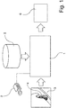
- Figure 1 depicts a variation for the implementing the method according to the invention for predicting a change in a direction of travel of a vehicle with a central processing unit 1 which controls the sequence of the method according to the invention.
- the central processing unit 1 is equipped for example with a memory not depicted here in which programme instructions to be executed are filed and/or stored in a common form. At a minimum, these programme instructions include the process steps needed for the method.
- the central processing unit 1 is connected with a sensor 2 which is in the form of a camera as shown in the example of Figure 1 .
- This sensor 2 and/or camera is arranged such that it may capture a camera image 3 of a steerable wheel of a motor vehicle.
- the central processing unit 1 is connected with a memory or a database 5 for example.
- This memory or database 5 includes several data sets that represent, for example, an image of a steerable wheel 4 with an associated wheel angle. Such an image is also referred to as a reference image.
- a variety of reference images of the steerable wheel 4 along with their associated wheel angles are stored in a so-called reference image data set.
- the memory can comprise an external memory.
- the memory can be arranged as a memory integrated into the central processing unit 1.
- the data may be stored as single values and/or in a database.
- the central processing unit 1 may determine the reference image with the best conformity and in such a manner determine the current wheel angle of the wheel 4 that is in proximity to camera 2 by making a comparison between a current camera image 3 recorded and provided by camera 2 and the reference images stored in the database 5. Based on the results of this comparison or image comparison, the central processing unit 1 outputs an output value 6 which describes a deviation from the current direction of travel or vehicle trajectory or the maintenance of the current direction of travel or vehicle trajectory. In this manner the central processing unit 1 may, for example, predict an immanent lane change even before it actually occurs. This is possible because there is a temporal delay between the change in the wheel angle and the travel of the vehicle in the direction determined by the wheel angle.
- This output value 6 can, for example, be receive by an assistance system installed in the vehicle and, for example, be interpreted as an input value.
- the output value 6 may be used in a lane departure warning system in order to indicate an immanent lane change.
- the output value 6 may include information about the direction of travel. For example, this may permit the central processing unit 1 to recognise a change in the direction of travel and/or the vehicle trajectory of the vehicle to the left or to the right and output as and output value 6.
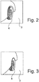
- Figure 2 depicts an example of a position of a wheel 4 in a first position recorded in a camera image 3 by camera 2 with a steering movement of the wheel 4 to the left.
- the intent is to adapt the system to the vehicle and/or the corresponding vehicle constellation during a training phase.
- reference images will be recorded with regard to several pre-set known wheel angles by means of camera 2 and to save them as a data set or reference image data set. Determining reference images in this manner may, for example, be made in each case after a change in the wheel angle of for example 5°, 3° or 1° (degrees).
- the position of wheel 4 in a straight-ahead position may be assigned a wheel angle of 0°.
- Setting the wheel 4 with a first wheel angle that evidences a positive sign for example a wheel angle of +3°, may be assigned to a steering wheel movement or a steering movement to the right.
- Setting the wheel 4 with a second wheel angle that evidences a negative sign for example a wheel angle of -3°, may be assigned to a steering wheel movement or a steering movement to the left. This assignment may be made in reverse order if needed.
- Adapting the system to the vehicle or the vehicle constellation may, for example, also be required after a tyre change.
- a change in the vehicle constellation may also be caused by a change in selection of the rims used for the wheel 4 or a change in the suspension travel of a chassis.
- different vehicle constellations i.e. different combinations of tyres, rims, chassis, for a reference vehicle may be determined for each training phase. Based on the different vehicle constellations, for which the respective reference images were stored and/or saved as a reference image data set, a corresponding reference image data set may be selected and, for example, transferred to a memory 5 in a vehicle that is to be finished as part of the manufacturing process.
- Figure 3 depicts an example of a position of a wheel 4 in a second position in a camera image recorded by camera 2.
- the wheel 4 comprising a rim with a tyre
- the wheel 4 shows a wheel angle of 0°
- the wheel 4 is thus in a position suitable for straight-ahead travel.
- an output value 6 is output by the central processing unit 1 that displays and/or predicts no change in the direction of travel of the vehicle, i.e. a continuation of the movement of the vehicle in the current direction of travel and/or along the current trajectory.
- an output value 6 is output by the central processing unit 1 that displays and/or predicts a change in the direction of travel of the vehicle: in this case a change in the current direction of travel of the vehicle to the right viewed from the direction of travel. In such cases, the vehicle will depart from its current trajectory and deviate from it to the right.
- an output value 6 is output by the central processing unit 1 that displays and/or predicts a change in the direction of travel of the vehicle: in this case a change in the current direction of travel of the vehicle to the left viewed from the direction of travel.
- An example of such a wheel angle and/or a corresponding position of the right front tyre of the motor vehicle in this position is depicted in Figure 2 . In such cases, the vehicle will depart from its current trajectory and deviate from it to the left.
- CNN convolutional neural network
- the intent is to record a camera image 3 via a camera arranged on the vehicle.
- the recorded camera image 3 may be transferred to the own vehicle.
- the method for predicting a change in a direction of travel of a vehicle may also be used in the other vehicle.
- the first step involves recognition of a vehicle within the field of view of the deployed camera 2. If the position of the vehicle is known localised within a so-called first area of a "bounding box", an area of interest and/or a second area is specified within the first area of the "bounding box" in which the vehicle's wheels must be located. In this case, the second area in which a steerable wheel 4 is expected is of particular interest.
- a current camera image 3 or multiple camera images 3 of the steerable wheel 4 are recorded in the second area.
- the prediction and/or output value 6 is determined by means of the manner described above by the CNN by means of a comparison between the current camera image 3 and the reference images.
- a vehicle equipped with a camera is driving in front of, behind and next to a vehicle making a lane change thus creating multiple reference image data sets to be processed by the CNN.
- the first step of recognising a vehicle within the field of view of deployed camera 2 may be accomplished using technologies such as CNN on PASCAL VOC, an ImageNET or an MS COCO.
Priority Applications (1)
| Application Number | Priority Date | Filing Date | Title |
|---|---|---|---|
| EP18163369.4A EP3543086A1 (fr) | 2018-03-22 | 2018-03-22 | Procédé pour prédire un changement dans la direction de déplacement d'un véhicule |
Applications Claiming Priority (1)
| Application Number | Priority Date | Filing Date | Title |
|---|---|---|---|
| EP18163369.4A EP3543086A1 (fr) | 2018-03-22 | 2018-03-22 | Procédé pour prédire un changement dans la direction de déplacement d'un véhicule |
Publications (1)
| Publication Number | Publication Date |
|---|---|
| EP3543086A1 true EP3543086A1 (fr) | 2019-09-25 |
Family
ID=61750052
Family Applications (1)
| Application Number | Title | Priority Date | Filing Date |
|---|---|---|---|
| EP18163369.4A Withdrawn EP3543086A1 (fr) | 2018-03-22 | 2018-03-22 | Procédé pour prédire un changement dans la direction de déplacement d'un véhicule |
Country Status (1)
| Country | Link |
|---|---|
| EP (1) | EP3543086A1 (fr) |
Cited By (6)
| Publication number | Priority date | Publication date | Assignee | Title |
|---|---|---|---|---|
| CN111611901A (zh) * | 2020-05-15 | 2020-09-01 | 北京百度网讯科技有限公司 | 车辆逆行检测方法、装置、设备以及存储介质 |
| CN111736604A (zh) * | 2020-06-24 | 2020-10-02 | 中国第一汽车股份有限公司 | 一种远程驾驶控制方法、装置、设备及存储介质 |
| EP3865375A1 (fr) * | 2020-02-17 | 2021-08-18 | Toyota Jidosha Kabushiki Kaisha | Appareil de commande de direction |
| CN114509087A (zh) * | 2022-02-21 | 2022-05-17 | 高德软件有限公司 | 定位方法、电子设备及计算机存储介质 |
| CN114771657A (zh) * | 2022-06-02 | 2022-07-22 | 安徽安凯汽车股份有限公司 | 一种方向轮转角检测系统 |
| DE102021211326A1 (de) | 2021-10-07 | 2023-04-13 | Zf Friedrichshafen Ag | Verfahren und Steuereinheit zum Erfassen einer Radstellung mindestens eines Rades eines Fahrzeugs und Fahrzeug |
Citations (8)
| Publication number | Priority date | Publication date | Assignee | Title |
|---|---|---|---|---|
| JPH05134036A (ja) * | 1991-11-14 | 1993-05-28 | Toyota Motor Corp | 車載用レーダ装置 |
| US5745870A (en) | 1994-09-14 | 1998-04-28 | Mazda Motor Corporation | Traveling-path prediction apparatus and method for vehicles |
| JP2004201223A (ja) * | 2002-12-20 | 2004-07-15 | Matsushita Electric Ind Co Ltd | 車両周辺監視装置および舵角検出方法 |
| US20080167820A1 (en) | 2007-01-04 | 2008-07-10 | Kentaro Oguchi | System for predicting driver behavior |
| US20090076702A1 (en) | 2005-09-15 | 2009-03-19 | Continental Teves Ag & Co. Ohg | Method and Apparatus for Predicting a Movement Trajectory |
| KR20120086577A (ko) * | 2011-01-26 | 2012-08-03 | 현대모비스 주식회사 | 카메라를 이용한 측면차량 검출 장치 및 방법 |
| JP2012176656A (ja) * | 2011-02-25 | 2012-09-13 | Fuji Heavy Ind Ltd | 駐車支援装置 |
| US9248856B2 (en) | 2013-11-29 | 2016-02-02 | Toyota Jidosha Kabushiki Kaisha | Vehicular steering controller |
-
2018
- 2018-03-22 EP EP18163369.4A patent/EP3543086A1/fr not_active Withdrawn
Patent Citations (8)
| Publication number | Priority date | Publication date | Assignee | Title |
|---|---|---|---|---|
| JPH05134036A (ja) * | 1991-11-14 | 1993-05-28 | Toyota Motor Corp | 車載用レーダ装置 |
| US5745870A (en) | 1994-09-14 | 1998-04-28 | Mazda Motor Corporation | Traveling-path prediction apparatus and method for vehicles |
| JP2004201223A (ja) * | 2002-12-20 | 2004-07-15 | Matsushita Electric Ind Co Ltd | 車両周辺監視装置および舵角検出方法 |
| US20090076702A1 (en) | 2005-09-15 | 2009-03-19 | Continental Teves Ag & Co. Ohg | Method and Apparatus for Predicting a Movement Trajectory |
| US20080167820A1 (en) | 2007-01-04 | 2008-07-10 | Kentaro Oguchi | System for predicting driver behavior |
| KR20120086577A (ko) * | 2011-01-26 | 2012-08-03 | 현대모비스 주식회사 | 카메라를 이용한 측면차량 검출 장치 및 방법 |
| JP2012176656A (ja) * | 2011-02-25 | 2012-09-13 | Fuji Heavy Ind Ltd | 駐車支援装置 |
| US9248856B2 (en) | 2013-11-29 | 2016-02-02 | Toyota Jidosha Kabushiki Kaisha | Vehicular steering controller |
Cited By (8)
| Publication number | Priority date | Publication date | Assignee | Title |
|---|---|---|---|---|
| EP3865375A1 (fr) * | 2020-02-17 | 2021-08-18 | Toyota Jidosha Kabushiki Kaisha | Appareil de commande de direction |
| CN111611901A (zh) * | 2020-05-15 | 2020-09-01 | 北京百度网讯科技有限公司 | 车辆逆行检测方法、装置、设备以及存储介质 |
| CN111611901B (zh) * | 2020-05-15 | 2023-10-03 | 北京百度网讯科技有限公司 | 车辆逆行检测方法、装置、设备以及存储介质 |
| CN111736604A (zh) * | 2020-06-24 | 2020-10-02 | 中国第一汽车股份有限公司 | 一种远程驾驶控制方法、装置、设备及存储介质 |
| CN111736604B (zh) * | 2020-06-24 | 2023-02-21 | 中国第一汽车股份有限公司 | 一种远程驾驶控制方法、装置、设备及存储介质 |
| DE102021211326A1 (de) | 2021-10-07 | 2023-04-13 | Zf Friedrichshafen Ag | Verfahren und Steuereinheit zum Erfassen einer Radstellung mindestens eines Rades eines Fahrzeugs und Fahrzeug |
| CN114509087A (zh) * | 2022-02-21 | 2022-05-17 | 高德软件有限公司 | 定位方法、电子设备及计算机存储介质 |
| CN114771657A (zh) * | 2022-06-02 | 2022-07-22 | 安徽安凯汽车股份有限公司 | 一种方向轮转角检测系统 |
Similar Documents
| Publication | Publication Date | Title |
|---|---|---|
| EP3543086A1 (fr) | Procédé pour prédire un changement dans la direction de déplacement d'un véhicule | |
| US11358608B2 (en) | Method and system for vehicular communication and safety monitoring of driving environment to provide early warnings in real-time | |
| US11256260B2 (en) | Generating trajectories for autonomous vehicles | |
| US9099006B2 (en) | Context-aware threat response arbitration | |
| JP5614055B2 (ja) | 運転支援装置 | |
| US11242040B2 (en) | Emergency braking for autonomous vehicles | |
| JP7205154B2 (ja) | 表示装置 | |
| US10919532B2 (en) | Apparatus and method for longitudinal control in automatic lane change in an assisted driving vehicle | |
| CN110254421B (zh) | 驾驶辅助系统 | |
| EP3880533B1 (fr) | Système de commande de véhicule et procédé | |
| CN112644511A (zh) | 用于自主车辆的智能升级策略 | |
| CN113104038B (zh) | 车辆换道控制方法、装置、电子设备及可读存储介质 | |
| CN113460081A (zh) | 车辆控制装置、车辆控制方法及存储介质 | |
| WO2018220851A1 (fr) | Dispositif et procédé de commande de véhicule permettant de commander un véhicule à conduite autonome | |
| CN109987090B (zh) | 驾驶辅助系统和方法 | |
| EP4316935A1 (fr) | Procédé et appareil pour obtenir une zone de changement de voie | |
| CN112977473A (zh) | 用于预测移动障碍物驶出十字路口的方法及系统 | |
| CN112009480A (zh) | 驾驶辅助系统 | |
| CN116135660A (zh) | 基于监控的驾驶员行为管理自动驾驶车辆的驾驶员接管的系统和方法 | |
| CN115366907A (zh) | 驾驶员的状态异常提醒方法、装置、车辆及存储介质 | |
| Pérez et al. | Vehicle control in ADAS applications: State of the art | |
| CN113460080A (zh) | 车辆控制装置、车辆控制方法及存储介质 | |
| CN113119945A (zh) | 一种基于环境模型的汽车高级辅助驾驶系统 | |
| CN113401056A (zh) | 显示控制装置、显示控制方法以及计算机可读取存储介质 | |
| CN113460083A (zh) | 车辆控制装置、车辆控制方法及存储介质 |
Legal Events
| Date | Code | Title | Description |
|---|---|---|---|
| PUAI | Public reference made under article 153(3) epc to a published international application that has entered the european phase |
Free format text: ORIGINAL CODE: 0009012 |
|
| AK | Designated contracting states |
Kind code of ref document: A1 Designated state(s): AL AT BE BG CH CY CZ DE DK EE ES FI FR GB GR HR HU IE IS IT LI LT LU LV MC MK MT NL NO PL PT RO RS SE SI SK SM TR |
|
| AX | Request for extension of the european patent |
Extension state: BA ME |
|
| STAA | Information on the status of an ep patent application or granted ep patent |
Free format text: STATUS: THE APPLICATION IS DEEMED TO BE WITHDRAWN |
|
| 18D | Application deemed to be withdrawn |
Effective date: 20200603 |