EP3543053A1 - Power unit structure for electrically driven vehicle - Google Patents
Power unit structure for electrically driven vehicle Download PDFInfo
- Publication number
- EP3543053A1 EP3543053A1 EP19162073.1A EP19162073A EP3543053A1 EP 3543053 A1 EP3543053 A1 EP 3543053A1 EP 19162073 A EP19162073 A EP 19162073A EP 3543053 A1 EP3543053 A1 EP 3543053A1
- Authority
- EP
- European Patent Office
- Prior art keywords
- control device
- electric motor
- unit
- electrically driven
- mounting part
- Prior art date
- Legal status (The legal status is an assumption and is not a legal conclusion. Google has not performed a legal analysis and makes no representation as to the accuracy of the status listed.)
- Granted
Links
Images




Classifications
-
- B—PERFORMING OPERATIONS; TRANSPORTING
- B60—VEHICLES IN GENERAL
- B60K—ARRANGEMENT OR MOUNTING OF PROPULSION UNITS OR OF TRANSMISSIONS IN VEHICLES; ARRANGEMENT OR MOUNTING OF PLURAL DIVERSE PRIME-MOVERS IN VEHICLES; AUXILIARY DRIVES FOR VEHICLES; INSTRUMENTATION OR DASHBOARDS FOR VEHICLES; ARRANGEMENTS IN CONNECTION WITH COOLING, AIR INTAKE, GAS EXHAUST OR FUEL SUPPLY OF PROPULSION UNITS IN VEHICLES
- B60K1/00—Arrangement or mounting of electrical propulsion units
-
- B—PERFORMING OPERATIONS; TRANSPORTING
- B60—VEHICLES IN GENERAL
- B60K—ARRANGEMENT OR MOUNTING OF PROPULSION UNITS OR OF TRANSMISSIONS IN VEHICLES; ARRANGEMENT OR MOUNTING OF PLURAL DIVERSE PRIME-MOVERS IN VEHICLES; AUXILIARY DRIVES FOR VEHICLES; INSTRUMENTATION OR DASHBOARDS FOR VEHICLES; ARRANGEMENTS IN CONNECTION WITH COOLING, AIR INTAKE, GAS EXHAUST OR FUEL SUPPLY OF PROPULSION UNITS IN VEHICLES
- B60K17/00—Arrangement or mounting of transmissions in vehicles
-
- B—PERFORMING OPERATIONS; TRANSPORTING
- B60—VEHICLES IN GENERAL
- B60K—ARRANGEMENT OR MOUNTING OF PROPULSION UNITS OR OF TRANSMISSIONS IN VEHICLES; ARRANGEMENT OR MOUNTING OF PLURAL DIVERSE PRIME-MOVERS IN VEHICLES; AUXILIARY DRIVES FOR VEHICLES; INSTRUMENTATION OR DASHBOARDS FOR VEHICLES; ARRANGEMENTS IN CONNECTION WITH COOLING, AIR INTAKE, GAS EXHAUST OR FUEL SUPPLY OF PROPULSION UNITS IN VEHICLES
- B60K17/00—Arrangement or mounting of transmissions in vehicles
- B60K17/04—Arrangement or mounting of transmissions in vehicles characterised by arrangement, location or kind of gearing
- B60K17/12—Arrangement or mounting of transmissions in vehicles characterised by arrangement, location or kind of gearing of electric gearing
-
- H—ELECTRICITY
- H02—GENERATION; CONVERSION OR DISTRIBUTION OF ELECTRIC POWER
- H02K—DYNAMO-ELECTRIC MACHINES
- H02K11/00—Structural association of dynamo-electric machines with electric components or with devices for shielding, monitoring or protection
- H02K11/30—Structural association with control circuits or drive circuits
- H02K11/35—Devices for recording or transmitting machine parameters, e.g. memory chips or radio transmitters for diagnosis
-
- H—ELECTRICITY
- H02—GENERATION; CONVERSION OR DISTRIBUTION OF ELECTRIC POWER
- H02K—DYNAMO-ELECTRIC MACHINES
- H02K5/00—Casings; Enclosures; Supports
- H02K5/04—Casings or enclosures characterised by the shape, form or construction thereof
- H02K5/10—Casings or enclosures characterised by the shape, form or construction thereof with arrangements for protection from ingress, e.g. water or fingers
-
- H—ELECTRICITY
- H02—GENERATION; CONVERSION OR DISTRIBUTION OF ELECTRIC POWER
- H02K—DYNAMO-ELECTRIC MACHINES
- H02K5/00—Casings; Enclosures; Supports
- H02K5/24—Casings; Enclosures; Supports specially adapted for suppression or reduction of noise or vibrations
-
- H—ELECTRICITY
- H02—GENERATION; CONVERSION OR DISTRIBUTION OF ELECTRIC POWER
- H02K—DYNAMO-ELECTRIC MACHINES
- H02K7/00—Arrangements for handling mechanical energy structurally associated with dynamo-electric machines, e.g. structural association with mechanical driving motors or auxiliary dynamo-electric machines
- H02K7/006—Structural association of a motor or generator with the drive train of a motor vehicle
-
- B—PERFORMING OPERATIONS; TRANSPORTING
- B60—VEHICLES IN GENERAL
- B60K—ARRANGEMENT OR MOUNTING OF PROPULSION UNITS OR OF TRANSMISSIONS IN VEHICLES; ARRANGEMENT OR MOUNTING OF PLURAL DIVERSE PRIME-MOVERS IN VEHICLES; AUXILIARY DRIVES FOR VEHICLES; INSTRUMENTATION OR DASHBOARDS FOR VEHICLES; ARRANGEMENTS IN CONNECTION WITH COOLING, AIR INTAKE, GAS EXHAUST OR FUEL SUPPLY OF PROPULSION UNITS IN VEHICLES
- B60K1/00—Arrangement or mounting of electrical propulsion units
- B60K2001/001—Arrangement or mounting of electrical propulsion units one motor mounted on a propulsion axle for rotating right and left wheels of this axle
Definitions
- the present invention relates to a power unit structure for an electrically driven vehicle.
- a power unit structure of mechatronical integration type in which a transmission which converts the revolution of an electric motor is arranged along the axle direction between the electric motor and an inverter (control device) which performs rotation control of the electric motor (for example, refer to Patent Document 1).
- this power unit structure three-phase power lines connecting the electric motor and inverter are arranged to penetrate the transmission case.
- Patent Document 1 Japanese Unexamined Patent Application, Publication No. 2013-173425
- the present invention has been made taking account of the above, and the object thereof is to provide a power unit structure for an electrically driven vehicle which can decrease design man-hours as well as raise the rigidity of the unit.
- a first aspect of the present invention provides a power unit structure (for example, the power unit structure 1 described later) for an electrically driven vehicle (for example, the electrically driven vehicle 9 described later), including: an electric motor unit (for example, the electric motor unit 2 described later) consisting of a central case (for example, the central case 21 described later), an electric motor case (for example, the electric motor case 22 described later) which houses an electric motor (for example, the electric motor 221 described later) mounted on one side of the central case, and a transmission case (for example, the transmission case 23 described later) which houses a transmission (for example, the transmission 231 described later) mounted at another side of the central case; and a control device unit (for example, the control device unit 3 described later) which controls the electric motor, in which the control device unit includes: a first mounting part (for example, the first mounting part 31 described later) which is a mounting part of a power supply unit that supplies electric power to the electric motor, and a second mounting part (for example, the second mounting part 32 described later) which fixes the
- the first aspect of the present invention it is possible to decrease the design man-hours, without needing to consider interference with the gears of the transmission, by directly mounting the first mounting part, which is the mounting part of the power supply unit of the control device unit to the electric motor, i.e. electrical fastener, to the central case.
- the second mounting part of the control device unit it is possible to mount the control device unit to span a plurality of members constituting the electric motor unit, and possible to raise the rigidity of the unit, while suppressing enlargement in the height direction of the unit.
- control device unit and the transmission case are disposed so as to overlap each other when viewed from a vertical direction.
- the control device unit and transmission case by arranging the control device unit and transmission case so as to overlap each other when viewing from the vertical direction, it is possible to shorten the dimension in the mounting direction upon mounting the control device unit to the electric motor unit, and possible to reduce the size of the power unit structure of the electrically driven vehicle.
- the control device unit in the power unit structure for an electrically driven vehicle as described in the first or second aspect, it is preferable for the control device unit to consists of a control device (for example, the control device 30 described later) which controls the electric motor, and a bracket (for example, the bracket 320 described later) which supports below the control device, the first mounting part to be formed at the control device, and the second mounting part to be formed at the bracket.
- a control device for example, the control device 30 described later
- a bracket for example, the bracket 320 described later
- the second mounting part 32 in the bracket which supports below the control device, after preferentially fastening the first mounting part which ensures electrical connection, it is possible to absorb with the second mounting part any gap for clearance occurring from the configuring mounting the control device unit to span a plurality of members constituting the electric motor unit.
- the bracket by supporting below the control device by the bracket, it is possible to suppress sound radiation of the control device from vibration transmitted from the side of the electric motor and transmission.
- the first mounting part and a mounted part (for example, the mounted part 20 described later) of the central case connected to the first mounting part prefferably be disposed so as to run along an upper end (for example, the upper end 10 described later) of the power unit structure for an electrically driven vehicle.
- the first mounting part which is a mounting part of the power supply unit given mounting priority is arranged so as to run along the upper end of the power unit structure of the electrically driven vehicle, it is possible to assemble the first mounting part during assembly work while visually confirming, and thus possible to suppress erroneous assembly. In addition, it is possible to suppress wetting from water being heaved up from the vehicle bottom, by arranging above the first mounting part, which is the electrical connection part.
- the bracket in the power unit structure for an electrically driven vehicle as described in the third or fourth, it is preferable for the bracket to consist of a support part (for example, the support part 321 described later) which supports the control device, and a pair of legs (for example, the pair of legs 322, 322 described later) which extends from the support part towards downwards; and an accessory (for example, the electric oil pump 7 described later) mounted to the electric motor unit to be disposed at a position sandwiched by the pair of legs.
- a support part for example, the support part 321 described later
- a pair of legs for example, the pair of legs 322, 322 described later
- the accessory by arranging the accessory at a position sandwiched by the pair of legs which extend from the support part of the bracket downwards, if assembly is performed at the wrong angle upon assembling the first mounting part, which is an electrical connection part, while visually confirming, the legs of the bracket will interfere with the accessory. It is thereby possible to know that assembly is not being performed correctly, and possible to more reliably suppress erroneous assembly.
- the accessory positioned between the pair of legs can be protected from impact during collision.
- the support part of the bracket in the power unit structure for an electrically driven vehicle as described in the fifth aspect, it is preferable for the support part of the bracket to be formed in a substantially C-shape which surrounds a center of gravity of the control device when viewing the control device unit from below; and the pair of legs to extend from a position sandwiched by two fixing points (for example, the fixing points 323, 323 described later) of the support part to the control device towards downwards, when viewing from one side in the longitudinal direction of the control device.
- the support part of the bracket in a substantially C-shape surrounding the center of gravity of the control device when viewed from below, and forming the pair of legs extending downwards from a position sandwiched by the two fixing points of the support part when viewed from one of the longitudinal directions of the control device, it is possible to stably fix the control device. It is thereby possible to effectively suppress sound radiation of the control device by vibration transmitted from the electric motor and transmission side.
- control device unit in the power unit structure for an electrically driven vehicle as described in any one of the first to sixth aspects, it is preferable for the control device unit to be disposed vehicle rearward, and to be disposed more vehicle forward than the electric motor unit.
- the seventh aspect of the present invention by arranging the control device unit more vehicle forward than the electric motor unit, it is possible to accept the load during rear collision by the electric motor unit, which is a rigid body made of metal, and thus possible to protect the control device unit.
- the control device in the power unit structure for an electrically driven vehicle as described in the seventh aspect, it is preferable for the control device to have a connection part (for example, the connection part 33 described later), to which a diagnostic device for the control device is connected, formed at a rear end face which is vehicle rearward.
- a connection part for example, the connection part 33 described later
- the eighth aspect of the present invention by forming, at the rear end face of the vehicle rear, the connection part to which diagnostic equipment of the control device is connected, it becomes possible to diagnose by simply removing the bumper without unloading units for the electrically driven vehicle from the vehicle during fault diagnosis in service, and thus it is possible to decrease the service workload.
- the U direction is up
- D direction is down
- Fr direction is vehicle forward
- Rr is vehicle rearward
- R direction is the right direction viewing from the driver's seat of the vehicle (vehicle width right side
- L direction is the left direction viewing from the driver's seat of the vehicle (vehicle width left side).
- FIG. 1 is a perspective view showing the arrangement and outline configuration of a power unit structure 1 for an electrically driven vehicle 9 according to an embodiment of the present invention.
- the power unit structure 1 for the electrically driven vehicle 9 according to the present embodiment is arranged at vehicle rearward (rear side) of the electrically driven vehicle 9.
- the power unit structure 1 for the electrically driven vehicle 9 according to the present embodiment is arranged above a rear frame 90 configuring a vehicle body rear of the electrically driven vehicle 9.
- the rear frame 90 is configured from a first rear frame 91, a pair of second rear frames 92, 92, and a third rear frame 93.
- the first rear frame 91 extends in the vehicle width direction at the rear part of the vehicle 9.
- the pair of second rear frames 92, 92 is connected to both ends in the vehicle width direction of the first rear frame 91, and respectively extends from these connection parts towards vehicle forwards.
- the third rear frame 93 extends in the vehicle width direction so as to connect bridging the vehicle forward side of the pair of second rear frames 92, 92.
- the power unit structure 1 for the electrically driven vehicle 9 according to the present embodiment is mounted on the rear frame 90 configured in a substantially rectangular shape by this first rear frame 91, pair of second rear frames 92, 92 and third rear frame 93.
- the power unit structure 1 for the electrically driven vehicle 9 includes an electric motor unit 2, and control device unit 3.
- the electric motor unit 2 is arranged on the R direction side, and the control device unit 3 is arranged on the L direction side.
- the electric motor unit 2 is connected to an axle 82 connecting the pair of left and right drive wheels 81, and the control device unit 3 is mounted to this electric motor unit 2.
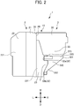
- FIG. 2 is a view looking from vehicle rearward at the power unit structure 1 for the electrically driven vehicle 9 according to the present embodiment.
- FIG. 3 is a view looking from vehicle rearward at the power unit structure 1 for the electrically driven vehicle 9 according to an embodiment of the present invention, and shows a state when mounting the control device unit 3 to the electric motor unit 2.
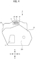
- FIG. 4 is a view looking from the R direction at the electric motor unit 2 prior to mounting the control device unit 3.
- FIG. 5 is a view looking from above at the electric motor unit 2 prior to mounting the control device unit 3.
- FIG. 5 shows a state removing a cover of each case among a center case 21, electric motor case 22 and transmission case 23.
- the electric motor unit 2 is configured from the center case 21, electric motor case 22 and transmission case 23.
- the center case 21 is arranged between the electric motor case 22 and transmission case 23 described later.
- the electric motor case 22 is mounted to one side of the center case 21 (L direction side as shown in FIG. 2 , for example), and houses the electric motor 221.
- the transmission case 23 is mounted to the other side of the center case 21 (R direction side as shown in FIG. 2 , for example), and houses the transmission 231.
- the control device unit 3 is a control device unit having a control device 30 which controls the electric motor 221, and is a so-called PCU (power control unit). This control device unit 3 is mounted from the R direction side to the L direction side of the electric motor unit 2 by a first mounting part 31 and second mounting part 32.
- the first mounting part 31 is a mounting part of a power supply unit which supplies electric power to the electric motor 221.
- the first mounting part 31 is an electrical connection part between the control device unit 3 and electric motor unit 2.
- This first mounting part 31 is formed at an end face on the L direction side at the top of the control device 30 in the power unit structure 1 for the electrically driven vehicle 9 according to the present embodiment.
- the second mounting part 32 is a mounting part for fixing the control device unit 3 to the electric motor unit 2.
- the second mounting part 32 is a mechanical connection part between the control device unit 3 and electric motor unit 2.
- This second mounting part 32 is formed at an end face on the L direction side of a bracket 320 described later, in the power unit structure 1 for the electrically driven vehicle 9 according to the present embodiment.
- the control device unit 3 and transmission case 23 are arranged so as to overlap each other when viewed from the vertical direction.
- the transmission case 23 is arranged biasing towards the lower side of the electric motor unit 2
- the control device unit 3 is arranged biasing towards the upper side of the electric motor unit 2.
- this control device unit 3 and transmission case 23 have vertical direction positions which are partly displaced, while positions in the vehicle width direction partly overlap each other. The mounting of the first mounting part 31 to the center case 21 and mounting of the second mounting part 32 to the transmission case 23 thereby become possible.
- the aforementioned first mounting part 31 is connected to a mounted part 20 of the center case 21, which is connected to the first mounting part 31.
- the first mounting part 31 is an electrical connection part between the control device unit 3 and electric motor unit 2 as mentioned above; therefore, the first mounting part 31 and mounted part 20 have a three-phase meeting face 40 of the three-phase power lines (bus bar) 41 of the electric motor 221, as shown in FIG. 4 and FIG. 5 .
- the first mounting part 31 is electrically connected to this three-phase terminal 4.
- FIPG Formmed In Place Gasket
- the three-phase power lines 41 of the electric motor 221 has one end connected to the electric motor 221, and the other end connected to the aforementioned three-phase terminal 4.
- an observation window 61 is formed, whereby it is configured so that an operator can easily confirm whether or not an electrical connection between the three-phase terminal 4 and first mounting part 31 is being reliably made.
- the first mounting part 31 is arranged at a substantially central part in the longitudinal direction (vehicle width direction) of the control device 30.
- the mounted part 20 is arranged at a substantially central part in the longitudinal direction (vehicle width direction) of the center case 21. Wetting is further suppressed by the water heaved up from the vehicle bottom, and the water-incursion resistance is further raised.
- FIGS. 6 to 9 are views for explaining the mounting sequence of the power unit structure 1 for the electrically driven vehicle 9 according to the present embodiment. More specifically, FIG. 6 is a perspective view showing a state when mounting the bracket 320 to the control device unit 3.
- FIG. 7 is a perspective view showing a state when mounting the control device unit 3 to the electric motor unit 2.
- FIG. 8 is a view looking from the R direction at a state when mounting the control device unit 3 to the electric motor unit 2.
- FIG. 9 is a view looking from the D direction at a state when mounting the control device unit 3 to the electric motor unit 2.
- the second mounting part 32 is formed in the bracket 320 which supports below the control device 30.
- the bracket 320 consists of a support part 321 which supports the control device 30, and a pair of legs 322, 322 which extends from the support part 321 downwards.
- the support part 321 of the bracket 320 is formed in a substantially C-shape so as to surround the center of gravity 3c of the control device 30, when viewing the control device unit 3 from the D direction (downwards).
- This support part 321 is mounted to the lower face of the control device unit 3 by configuring so that the open side thereof faces the L direction.
- the pair of legs 322, 322 when viewing from one of the longitudinal directions (vehicle width direction) of the control device 30, extends towards the D direction (downwards) from a position sandwiched by the two fixing points 323, 323 of the support part relative to the control device 30 (refer to FIGS. 2 and 3 ).
- the pair of legs 322, 322 is formed so as to slope downwards as approaching from one end side in the vehicle width direction of the support part 321 (R direction side) to the other end side (L direction side).
- the second mounting part 32 is configured by second mounting sections 32a, 32a formed at an end face in the L direction side of the support part 321, and second mounting sections 32b, 32b formed at the leading end face (lower end) of the pair of legs 322, 322.
- the control device unit 3 is mechanically connected to the transmission case 23 via the bracket 320 by way of these second mounting parts 32.
- the bracket 320 is provisionally fixed to the lower surface of the control device unit 3 by temporarily tightening screws S. At this time, the bracket 320 is temporarily fixed to the control device unit 3 in a movable state in the mounting direction of the control device unit 3 to the motor unit 2.
- the control device unit 3 to which the bracket 320 was temporarily fixed at the lower surface is mounted to the side face of the electric motor unit 2 from the R direction side towards the L direction side. More specifically, first, the first mounting part 31 is securely mounted to the mounted part 20 of the central case 21. At this time, since the first mounting part 31 and mounted part 20 are arranged so as to run along the upper end 10 of the power unit structure 1 of the electrically driven vehicle 9 as shown in FIG. 7 , it becomes possible for the operator to easily perform confirmation as to whether or not electrical connected between the first mounting part 31 and mounted part 20 is reliably made by way of the observation window 61 formed on the top of the electric motor unit 2, and the observation window 62 formed on the top of the control device unit 3.
- the second mounting sections 32a, 32a, 32b, 32b of the bracket 320 are mounted to the mounting surface on the side face of the transmission case 23.
- the bracket 320 in the case of there being no clearance between the mounting surface of the transmission case 23 and the mounting surface of the second mounting sections 32a, 32a, 32b, 32b, after moving the bracket 320 in the opposite direction from the mounting direction, and the screw fixing the second mounting sections 32a, 32a, 32b, 32b, the screws of the bracket 320 which had been temporarily fastened to the control device unit 3 are final tightened.
- the control device unit 3 is thereby completed.
- the electric oil pump 7 serving as an accessory mounted to the electric motor unit 2 is arranged at a position sandwiched by the pair of legs 322, 322.
- the electric oil pump 7 functions as a positioning member of the control device unit 3 relative to the electric motor unit 2. Therefore, in the case of the position of the control device unit 3 relative to the electric motor unit 2 being shifted from prescribed, since the leg 322 of the bracket 320 would interfere with the electric oil pump 7, erroneous assembly becomes suppressible.
- FIG. 10 is a view looking from the L direction (vehicle width left side) at the power unit structure 1 of the electrically driven vehicle 9 according to the present embodiment.
- the control device unit 3 is arranged more to the Fr direction side than the electric motor unit 2.
- the position P2 of the Rr direction-side end face of the control device unit 3 (control device 30) is positioned more to the Fr direction side than the position P1 of the Rr direction-side end face of the electric motor unit 2.
- the electric motor unit 2 preferentially receives the shock relative to the body member BM, which receives shock during collision from behind (rear collision) to deform and offset. For this reason, it is configured so that shock to the control device unit 3 is mitigated.
- FIG. 11 is a perspective view when looking from behind at the vehicle 9 to which the power unit structure 1 of the electrically driven vehicle 9 according to the present embodiment is equipped. It should be noted that FIG. 11 shows a state removing the rear bumper of the vehicle 9. As shown in FIG. 11 , in the control device unit 3, the connection part 33 to which diagnostic equipment (not shown) of the control device 30 is connected, is formed at the Rr direction-side end face. Diagnosis becomes possible by simply removing the rear bumper, without unloading the power unit structure 1 of the electrically driven vehicle 9 from the vehicle 9 during fault diagnosis in service.
- the power unit structure 1 of the electrically driven vehicle 9 according to the present embodiment equipped with the above configuration, the following effects are exerted.
- the present embodiment it is possible to decrease the design man-hours, without needing to consider interference with the gears of the transmission 231, by directly mounting the first mounting part 31, which is the mounting part of the power supply unit of the control device unit 3 to the electric motor 221, i.e. electrical fastener, to the central case 21.
- the control device unit 3 by mounting the second mounting part 32 of the control device unit 3 to the transmission case 23, it is possible to mount the control device unit 3 to span a plurality of members constituting the electric motor unit 2 (more specifically, central case 21 and transmission case 23), and possible to raise the rigidity of the unit, while suppressing enlargement in the height direction of the unit.
- control device unit 3 and transmission case 23 are arranged so as to overlap each other when viewing from the vertical direction, it is possible to shorten the dimension in the mounting direction upon mounting the control device unit 3 to the electric motor unit 2, and possible to reduce the size of the power unit structure 1 of the electrically driven vehicle 9.
- the bracket 320 which supports below the control device 30, after preferentially fastening the first mounting part 31 which ensures electrical connection, it is possible to absorb with the second mounting part 32 any gap for clearance occurring from the configuring mounting the control device unit 3 to span a plurality of members constituting the electric motor unit 2.
- the bracket 320 by supporting below the control device 30 by the bracket 320, it is possible to suppress sound radiation of the control device 30 from vibration transmitted from the side of the electric motor 221 and transmission 231.
- the first mounting part 31, which is a mounting part of the power supply unit given mounting priority is arranged so as to run along the upper end 10 of the power unit structure 1 of the electrically driven vehicle 9, it is possible to assemble the first mounting part 31 during assembly work while visually confirming, and thus possible to suppress erroneous assembly. In addition, it is possible to suppress wetting from water being heaved up from the vehicle bottom, by arranging above the first mounting part 31, which is the electrical connection part.
- the electric oil pump 7 serving as an accessory at a position sandwiched by the pair of legs 322, 322 which extend from the support part 321 of the bracket 320 downwards, if assembly is performed at the wrong angle upon assembling the first mounting part 31, which is an electrical connection part, while visually confirming, the legs 322 of the bracket 320 will interfere with the electric oil pump 7. It is thereby possible to know that assembly is not being performed correctly, and possible to more reliably suppress erroneous assembly.
- the electric oil pump 7 positioned between the pair of legs 322, 322 can be protected from impact during collision.
- the support part 321 of the bracket 320 in a substantially C-shape surrounding the center of gravity of the control device 30 when viewed from below, and forming the pair of legs 322, 322 extending downwards from a position sandwiched by the two fixing points 323, 323 of the support part 321 when viewed from one of the longitudinal directions (vehicle width direction) of the control device 30, it is possible to stably fix the control device 30. It is thereby possible to effectively suppress sound radiation of the control device 30 by vibration transmitted from the electric motor 221 and transmission 231 side.
- control device unit 3 by arranging the control device unit 3 more vehicle forward than the electric motor unit 2, it is possible to accept the load during rear collision by the electric motor unit 2, which is a rigid body made of metal, and thus possible to protect the control device unit 3.
- the connection part 33 to which diagnostic equipment of the control device 30 is connected by forming, at the rear end face of the vehicle rear, the connection part 33 to which diagnostic equipment of the control device 30 is connected, it becomes possible to diagnose by simply removing the bumper without unloading the power unit structure 1 of the electrically driven vehicle 9 from the vehicle 9 during fault diagnosis in service, and thus it is possible to decrease the service workload.
- a control device unit (3) for an electrically driven vehicle (9) includes: a first mounting part (31) which is a mounting part of a power supply unit that supplies electric power to an electric motor (221), and a second mounting part (32) which fixes the control device unit (3) to an electric motor unit (2); and the control device unit (3) is mounted from a transmission case (23) side of the electric motor unit (2) towards an electric motor case (22) side, the first mounting part (31) being mounted to a central case (21), and the second mounting part (32) being mounted to the transmission case (23).
Landscapes
- Engineering & Computer Science (AREA)
- Chemical & Material Sciences (AREA)
- Combustion & Propulsion (AREA)
- Transportation (AREA)
- Mechanical Engineering (AREA)
- Power Engineering (AREA)
- Arrangement Or Mounting Of Propulsion Units For Vehicles (AREA)
- Motor Power Transmission Devices (AREA)
- Electric Propulsion And Braking For Vehicles (AREA)
Abstract
Description
- The present invention relates to a power unit structure for an electrically driven vehicle.
- Conventionally, a power unit structure of mechatronical integration type has been disclosed in which a transmission which converts the revolution of an electric motor is arranged along the axle direction between the electric motor and an inverter (control device) which performs rotation control of the electric motor (for example, refer to Patent Document 1). With this power unit structure, three-phase power lines connecting the electric motor and inverter are arranged to penetrate the transmission case.
- Patent Document 1: Japanese Unexamined Patent Application, Publication No.
2013-173425 - However, with the power unit structure of
Patent Document 1, it is necessary to design so that each built-in gear and through hole of the three-phase power lines do not interfere, upon design of the transmission case, and thus there has been a problem in that the design man-hours increase. In addition, the electric motor, transmission and inverter are fastened linearly to line up in a row; therefore, there has been a problem in being weak to external input from a direction orthogonal to the aligning direction, and a high voltage part is exposed during vehicle collision, etc. - The present invention has been made taking account of the above, and the object thereof is to provide a power unit structure for an electrically driven vehicle which can decrease design man-hours as well as raise the rigidity of the unit.
- A first aspect of the present invention provides a power unit structure (for example, the
power unit structure 1 described later) for an electrically driven vehicle (for example, the electrically drivenvehicle 9 described later), including: an electric motor unit (for example, theelectric motor unit 2 described later) consisting of a central case (for example, thecentral case 21 described later), an electric motor case (for example, theelectric motor case 22 described later) which houses an electric motor (for example, theelectric motor 221 described later) mounted on one side of the central case, and a transmission case (for example, thetransmission case 23 described later) which houses a transmission (for example, thetransmission 231 described later) mounted at another side of the central case; and a control device unit (for example, thecontrol device unit 3 described later) which controls the electric motor, in which the control device unit includes: a first mounting part (for example, thefirst mounting part 31 described later) which is a mounting part of a power supply unit that supplies electric power to the electric motor, and a second mounting part (for example, thesecond mounting part 32 described later) which fixes the control device unit to the electric motor unit; and in which the control device unit is mounted from the other side of the electric motor unit towards the one side, the first mounting part is mounted to the central case, and the second mounting part is mounted to the transmission case. - According to the first aspect of the present invention, it is possible to decrease the design man-hours, without needing to consider interference with the gears of the transmission, by directly mounting the first mounting part, which is the mounting part of the power supply unit of the control device unit to the electric motor, i.e. electrical fastener, to the central case. In addition, by mounting the second mounting part of the control device unit to the transmission case, it is possible to mount the control device unit to span a plurality of members constituting the electric motor unit, and possible to raise the rigidity of the unit, while suppressing enlargement in the height direction of the unit.
- According to a second aspect of the present invention, in the power unit structure for an electrically driven vehicle as described in the first aspect, it is preferable for the control device unit and the transmission case to be disposed so as to overlap each other when viewed from a vertical direction.
- According to the second aspect of the present invention, by arranging the control device unit and transmission case so as to overlap each other when viewing from the vertical direction, it is possible to shorten the dimension in the mounting direction upon mounting the control device unit to the electric motor unit, and possible to reduce the size of the power unit structure of the electrically driven vehicle.
- According to a third aspect of the present invention, in the power unit structure for an electrically driven vehicle as described in the first or second aspect, it is preferable for the control device unit to consists of a control device (for example, the
control device 30 described later) which controls the electric motor, and a bracket (for example, thebracket 320 described later) which supports below the control device, the first mounting part to be formed at the control device, and the second mounting part to be formed at the bracket. - According to the third aspect of the present invention, by forming the
second mounting part 32 in the bracket which supports below the control device, after preferentially fastening the first mounting part which ensures electrical connection, it is possible to absorb with the second mounting part any gap for clearance occurring from the configuring mounting the control device unit to span a plurality of members constituting the electric motor unit. In addition, by supporting below the control device by the bracket, it is possible to suppress sound radiation of the control device from vibration transmitted from the side of the electric motor and transmission. - According to a fourth aspect of the present invention, in the power unit structure for an electrically driven vehicle as described in any one of the first to third aspects, it is preferable for the first mounting part and a mounted part (for example, the mounted
part 20 described later) of the central case connected to the first mounting part to be disposed so as to run along an upper end (for example, theupper end 10 described later) of the power unit structure for an electrically driven vehicle. - According to the fourth aspect of the present invention, since the first mounting part, which is a mounting part of the power supply unit given mounting priority is arranged so as to run along the upper end of the power unit structure of the electrically driven vehicle, it is possible to assemble the first mounting part during assembly work while visually confirming, and thus possible to suppress erroneous assembly. In addition, it is possible to suppress wetting from water being heaved up from the vehicle bottom, by arranging above the first mounting part, which is the electrical connection part.
- According to a fifth aspect of the present invention, in the power unit structure for an electrically driven vehicle as described in the third or fourth, it is preferable for the bracket to consist of a support part (for example, the
support part 321 described later) which supports the control device, and a pair of legs (for example, the pair oflegs electric oil pump 7 described later) mounted to the electric motor unit to be disposed at a position sandwiched by the pair of legs. - According to the fifth aspect of the present invention, by arranging the accessory at a position sandwiched by the pair of legs which extend from the support part of the bracket downwards, if assembly is performed at the wrong angle upon assembling the first mounting part, which is an electrical connection part, while visually confirming, the legs of the bracket will interfere with the accessory. It is thereby possible to know that assembly is not being performed correctly, and possible to more reliably suppress erroneous assembly. In addition, the accessory positioned between the pair of legs can be protected from impact during collision.
- According to a sixth aspect of the present invention, in the power unit structure for an electrically driven vehicle as described in the fifth aspect, it is preferable for the support part of the bracket to be formed in a substantially C-shape which surrounds a center of gravity of the control device when viewing the control device unit from below; and the pair of legs to extend from a position sandwiched by two fixing points (for example, the
fixing points - According to the sixth aspect of the present invention, by forming the support part of the bracket in a substantially C-shape surrounding the center of gravity of the control device when viewed from below, and forming the pair of legs extending downwards from a position sandwiched by the two fixing points of the support part when viewed from one of the longitudinal directions of the control device, it is possible to stably fix the control device. It is thereby possible to effectively suppress sound radiation of the control device by vibration transmitted from the electric motor and transmission side.
- According to a seventh aspect of the present invention, in the power unit structure for an electrically driven vehicle as described in any one of the first to sixth aspects, it is preferable for the control device unit to be disposed vehicle rearward, and to be disposed more vehicle forward than the electric motor unit.
- According to the seventh aspect of the present invention, by arranging the control device unit more vehicle forward than the electric motor unit, it is possible to accept the load during rear collision by the electric motor unit, which is a rigid body made of metal, and thus possible to protect the control device unit.
- According to an eighth aspect of the present invention, in the power unit structure for an electrically driven vehicle as described in the seventh aspect, it is preferable for the control device to have a connection part (for example, the
connection part 33 described later), to which a diagnostic device for the control device is connected, formed at a rear end face which is vehicle rearward. - According to the eighth aspect of the present invention, by forming, at the rear end face of the vehicle rear, the connection part to which diagnostic equipment of the control device is connected, it becomes possible to diagnose by simply removing the bumper without unloading units for the electrically driven vehicle from the vehicle during fault diagnosis in service, and thus it is possible to decrease the service workload.
- According to the present invention, it is possible to provide a power unit structure for an electrically driven vehicle which can decrease design man-hours as well as raise the rigidity of the unit.
-
-
FIG. 1 is a perspective view showing the arrangement and outline configuration of a power unit structure for an electrically driven vehicle according to an embodiment of the present invention; -
FIG. 2 is a view looking from vehicle rearward at the power unit structure for an electrically driven vehicle according to an embodiment of the present invention; -
FIG. 3 is a view looking from vehicle rearward at the power unit structure for an electrically driven vehicle according to an embodiment of the present invention, and shows a state when mounting a control device unit to an electric motor unit; -
FIG. 4 is a view looking from a vehicle width right side (R direction)at the electric motor unit prior to mounting the control device unit; -
FIG. 5 is a view looking from above at the electric motor unit prior to mounting the control device unit; -
FIG. 6 is a view for explaining a mounting sequence of the power unit structure for an electrically driven according to an embodiment of the present invention, and is a perspective view showing a state when mounting a bracket to the control device unit; -
FIG. 7 is a view for explaining a mounting sequence of the power unit structure for an electrically driven according to an embodiment of the present invention, and is a perspective view showing a state when mounting the control device unit to the electric motor unit; -
FIG. 8 is a view for explaining a mounting sequence of the power unit structure for an electrically driven vehicle according to an embodiment of the present invention, and is a view looking from a vehicle width right side (R direction) at a state when mounting the control device unit to the electric motor unit; -
FIG. 9 is a view for explaining a mounting sequence of the power unit structure for an electrically driven vehicle according to an embodiment of the present invention, and is a view looking from below at a state when mounting the control device unit to the electric motor unit; -
FIG. 10 is a view looking from an L direction (vehicle width left side) at the power unit structure for an electrically driven vehicle according to an embodiment of the present invention; and -
FIG. 11 is a perspective view when looking from behind at the vehicle to which the power unit structure for an electrically driven vehicle according to an embodiment of the present invention was equipped. - Hereinafter, an embodiment of the present invention will be explained in detail while referencing the drawings. It should be noted that, in the drawings, the U direction is up, D direction is down, Fr direction is vehicle forward, Rr is vehicle rearward, R direction is the right direction viewing from the driver's seat of the vehicle (vehicle width right side, and L direction is the left direction viewing from the driver's seat of the vehicle (vehicle width left side).
-
FIG. 1 is a perspective view showing the arrangement and outline configuration of apower unit structure 1 for an electrically drivenvehicle 9 according to an embodiment of the present invention. As shown inFIG. 1 , thepower unit structure 1 for the electrically drivenvehicle 9 according to the present embodiment is arranged at vehicle rearward (rear side) of the electrically drivenvehicle 9. In addition, thepower unit structure 1 for the electrically drivenvehicle 9 according to the present embodiment is arranged above a rear frame 90 configuring a vehicle body rear of the electrically drivenvehicle 9. - The rear frame 90 is configured from a first
rear frame 91, a pair of secondrear frames rear frame 93. - The first
rear frame 91 extends in the vehicle width direction at the rear part of thevehicle 9. The pair of secondrear frames rear frame 91, and respectively extends from these connection parts towards vehicle forwards. The thirdrear frame 93 extends in the vehicle width direction so as to connect bridging the vehicle forward side of the pair of secondrear frames rear frame 91, pair of secondrear frames rear frame 93, thepower unit structure 1 for the electrically drivenvehicle 9 according to the present embodiment is mounted. - As shown in
FIG. 1 , thepower unit structure 1 for the electrically drivenvehicle 9 according to the present embodiment includes anelectric motor unit 2, andcontrol device unit 3. Theelectric motor unit 2 is arranged on the R direction side, and thecontrol device unit 3 is arranged on the L direction side. Theelectric motor unit 2 is connected to anaxle 82 connecting the pair of left andright drive wheels 81, and thecontrol device unit 3 is mounted to thiselectric motor unit 2. -
FIG. 2 is a view looking from vehicle rearward at thepower unit structure 1 for the electrically drivenvehicle 9 according to the present embodiment. In addition,FIG. 3 is a view looking from vehicle rearward at thepower unit structure 1 for the electrically drivenvehicle 9 according to an embodiment of the present invention, and shows a state when mounting thecontrol device unit 3 to theelectric motor unit 2.FIG. 4 is a view looking from the R direction at theelectric motor unit 2 prior to mounting thecontrol device unit 3.FIG. 5 is a view looking from above at theelectric motor unit 2 prior to mounting thecontrol device unit 3. However,FIG. 5 shows a state removing a cover of each case among acenter case 21,electric motor case 22 andtransmission case 23. - As shown in
FIG. 2 andFIG. 3 , theelectric motor unit 2 is configured from thecenter case 21,electric motor case 22 andtransmission case 23. - The
center case 21 is arranged between theelectric motor case 22 andtransmission case 23 described later. Theelectric motor case 22 is mounted to one side of the center case 21 (L direction side as shown inFIG. 2 , for example), and houses theelectric motor 221. Thetransmission case 23 is mounted to the other side of the center case 21 (R direction side as shown inFIG. 2 , for example), and houses thetransmission 231. - The
control device unit 3 is a control device unit having acontrol device 30 which controls theelectric motor 221, and is a so-called PCU (power control unit). Thiscontrol device unit 3 is mounted from the R direction side to the L direction side of theelectric motor unit 2 by a first mountingpart 31 and second mountingpart 32. - The first mounting
part 31 is a mounting part of a power supply unit which supplies electric power to theelectric motor 221. In other words, the first mountingpart 31 is an electrical connection part between thecontrol device unit 3 andelectric motor unit 2. This first mountingpart 31 is formed at an end face on the L direction side at the top of thecontrol device 30 in thepower unit structure 1 for the electrically drivenvehicle 9 according to the present embodiment. - The second mounting
part 32 is a mounting part for fixing thecontrol device unit 3 to theelectric motor unit 2. In other words, the second mountingpart 32 is a mechanical connection part between thecontrol device unit 3 andelectric motor unit 2. This second mountingpart 32 is formed at an end face on the L direction side of abracket 320 described later, in thepower unit structure 1 for the electrically drivenvehicle 9 according to the present embodiment. - As shown in
FIG. 2 andFIG. 3 , thecontrol device unit 3 andtransmission case 23 are arranged so as to overlap each other when viewed from the vertical direction. In more detail, thetransmission case 23 is arranged biasing towards the lower side of theelectric motor unit 2, and thecontrol device unit 3 is arranged biasing towards the upper side of theelectric motor unit 2. In other words, thiscontrol device unit 3 andtransmission case 23 have vertical direction positions which are partly displaced, while positions in the vehicle width direction partly overlap each other. The mounting of the first mountingpart 31 to thecenter case 21 and mounting of the second mountingpart 32 to thetransmission case 23 thereby become possible. - The aforementioned first mounting
part 31 is connected to amounted part 20 of thecenter case 21, which is connected to the first mountingpart 31. In addition, the first mountingpart 31 is an electrical connection part between thecontrol device unit 3 andelectric motor unit 2 as mentioned above; therefore, the first mountingpart 31 and mountedpart 20 have a three-phase meeting face 40 of the three-phase power lines (bus bar) 41 of theelectric motor 221, as shown inFIG. 4 andFIG. 5 . At the inside of this three-phase meeting face 40, three-phase terminals 4 of the three-phase power lines 41 are arranged, and the first mountingpart 31 is electrically connected to this three-phase terminal 4. It should be noted that, at the three-phase meeting face 40 of the three-phase power lines 41, a coating agent serving to adhere and seal called FIPG (Formed In Place Gasket) is coated, whereby the sealing property is ensured. - As shown in
FIG. 5 , the three-phase power lines 41 of theelectric motor 221 has one end connected to theelectric motor 221, and the other end connected to the aforementioned three-phase terminal 4. On the top face of thecenter case 21, anobservation window 61 is formed, whereby it is configured so that an operator can easily confirm whether or not an electrical connection between the three-phase terminal 4 and first mountingpart 31 is being reliably made. - In addition, as shown in
FIG. 4 andFIG. 5 , the first mountingpart 31 is arranged at a substantially central part in the longitudinal direction (vehicle width direction) of thecontrol device 30. Similarly, themounted part 20 is arranged at a substantially central part in the longitudinal direction (vehicle width direction) of thecenter case 21. Wetting is further suppressed by the water heaved up from the vehicle bottom, and the water-incursion resistance is further raised. - Next, while explaining the mounting sequence of the
power unit structure 1 for the electrically drivenvehicle 9 according to the present embodiment, a more detailed structure of thepower unit structure 1 will be explained. -
FIGS. 6 to 9 are views for explaining the mounting sequence of thepower unit structure 1 for the electrically drivenvehicle 9 according to the present embodiment. More specifically,FIG. 6 is a perspective view showing a state when mounting thebracket 320 to thecontrol device unit 3.FIG. 7 is a perspective view showing a state when mounting thecontrol device unit 3 to theelectric motor unit 2.FIG. 8 is a view looking from the R direction at a state when mounting thecontrol device unit 3 to theelectric motor unit 2.FIG. 9 is a view looking from the D direction at a state when mounting thecontrol device unit 3 to theelectric motor unit 2. - As shown in
FIG. 6 , the second mountingpart 32 is formed in thebracket 320 which supports below thecontrol device 30. Thebracket 320 consists of asupport part 321 which supports thecontrol device 30, and a pair oflegs support part 321 downwards. - The
support part 321 of thebracket 320 is formed in a substantially C-shape so as to surround the center ofgravity 3c of thecontrol device 30, when viewing thecontrol device unit 3 from the D direction (downwards). Thissupport part 321 is mounted to the lower face of thecontrol device unit 3 by configuring so that the open side thereof faces the L direction. - In addition, the pair of
legs control device 30, extends towards the D direction (downwards) from a position sandwiched by the two fixingpoints FIGS. 2 and3 ). In more detail, the pair oflegs - The second mounting
part 32 is configured by second mountingsections support part 321, and second mountingsections legs control device unit 3 is mechanically connected to thetransmission case 23 via thebracket 320 by way of these second mountingparts 32. - First, as shown in
FIG. 6 , thebracket 320 is provisionally fixed to the lower surface of thecontrol device unit 3 by temporarily tightening screws S. At this time, thebracket 320 is temporarily fixed to thecontrol device unit 3 in a movable state in the mounting direction of thecontrol device unit 3 to themotor unit 2. - Next, as shown in
FIG. 7 , thecontrol device unit 3 to which thebracket 320 was temporarily fixed at the lower surface is mounted to the side face of theelectric motor unit 2 from the R direction side towards the L direction side. More specifically, first, the first mountingpart 31 is securely mounted to themounted part 20 of thecentral case 21. At this time, since the first mountingpart 31 and mountedpart 20 are arranged so as to run along theupper end 10 of thepower unit structure 1 of the electrically drivenvehicle 9 as shown inFIG. 7 , it becomes possible for the operator to easily perform confirmation as to whether or not electrical connected between the first mountingpart 31 and mountedpart 20 is reliably made by way of theobservation window 61 formed on the top of theelectric motor unit 2, and theobservation window 62 formed on the top of thecontrol device unit 3. - Next, after it is confirmed that electrical connection of the first mounting
part 31 was reliably made, thesecond mounting sections bracket 320 are mounted to the mounting surface on the side face of thetransmission case 23. At this time, in the case of there being no clearance between the mounting surface of thetransmission case 23 and the mounting surface of thesecond mounting sections bracket 320 in the opposite direction from the mounting direction, and the screw fixing thesecond mounting sections bracket 320 which had been temporarily fastened to thecontrol device unit 3 are final tightened. On the other hand, in the case of having clearance between the mounting surface of thetransmission case 23 and mounting surface of thesecond mounting sections bracket 320 in the mounting direction to abut the mounting surface of thetransmission case 23, and then screw fixing thesecond mounting sections bracket 320 which had been temporarily fastened to thecontrol device unit 3 are final tightened. - Mounting of the
control device unit 3 to theelectric motor unit 2 is thereby completed. At this time, as shown inFIGS. 8 and9 , it is configured so that theelectric oil pump 7 serving as an accessory mounted to theelectric motor unit 2 is arranged at a position sandwiched by the pair oflegs electric oil pump 7 functions as a positioning member of thecontrol device unit 3 relative to theelectric motor unit 2. Therefore, in the case of the position of thecontrol device unit 3 relative to theelectric motor unit 2 being shifted from prescribed, since theleg 322 of thebracket 320 would interfere with theelectric oil pump 7, erroneous assembly becomes suppressible. - Next,
FIG. 10 is a view looking from the L direction (vehicle width left side) at thepower unit structure 1 of the electrically drivenvehicle 9 according to the present embodiment. As shown inFIG. 10 , thecontrol device unit 3 is arranged more to the Fr direction side than theelectric motor unit 2. In more detail, the position P2 of the Rr direction-side end face of the control device unit 3 (control device 30) is positioned more to the Fr direction side than the position P1 of the Rr direction-side end face of theelectric motor unit 2. Theelectric motor unit 2 preferentially receives the shock relative to the body member BM, which receives shock during collision from behind (rear collision) to deform and offset. For this reason, it is configured so that shock to thecontrol device unit 3 is mitigated. - In addition,
FIG. 11 is a perspective view when looking from behind at thevehicle 9 to which thepower unit structure 1 of the electrically drivenvehicle 9 according to the present embodiment is equipped. It should be noted thatFIG. 11 shows a state removing the rear bumper of thevehicle 9. As shown inFIG. 11 , in thecontrol device unit 3, theconnection part 33 to which diagnostic equipment (not shown) of thecontrol device 30 is connected, is formed at the Rr direction-side end face. Diagnosis becomes possible by simply removing the rear bumper, without unloading thepower unit structure 1 of the electrically drivenvehicle 9 from thevehicle 9 during fault diagnosis in service. - According to the
power unit structure 1 of the electrically drivenvehicle 9 according to the present embodiment equipped with the above configuration, the following effects are exerted. First, according to the present embodiment, it is possible to decrease the design man-hours, without needing to consider interference with the gears of thetransmission 231, by directly mounting the first mountingpart 31, which is the mounting part of the power supply unit of thecontrol device unit 3 to theelectric motor 221, i.e. electrical fastener, to thecentral case 21. In addition, by mounting the second mountingpart 32 of thecontrol device unit 3 to thetransmission case 23, it is possible to mount thecontrol device unit 3 to span a plurality of members constituting the electric motor unit 2 (more specifically,central case 21 and transmission case 23), and possible to raise the rigidity of the unit, while suppressing enlargement in the height direction of the unit. - In addition, according to the present embodiment, by arranging the
control device unit 3 andtransmission case 23 so as to overlap each other when viewing from the vertical direction, it is possible to shorten the dimension in the mounting direction upon mounting thecontrol device unit 3 to theelectric motor unit 2, and possible to reduce the size of thepower unit structure 1 of the electrically drivenvehicle 9. - In addition, according to the present embodiment, by forming the second mounting
part 32 in thebracket 320 which supports below thecontrol device 30, after preferentially fastening the first mountingpart 31 which ensures electrical connection, it is possible to absorb with the second mountingpart 32 any gap for clearance occurring from the configuring mounting thecontrol device unit 3 to span a plurality of members constituting theelectric motor unit 2. In addition, by supporting below thecontrol device 30 by thebracket 320, it is possible to suppress sound radiation of thecontrol device 30 from vibration transmitted from the side of theelectric motor 221 andtransmission 231. - In addition, according to the present embodiment, since the first mounting
part 31, which is a mounting part of the power supply unit given mounting priority is arranged so as to run along theupper end 10 of thepower unit structure 1 of the electrically drivenvehicle 9, it is possible to assemble the first mountingpart 31 during assembly work while visually confirming, and thus possible to suppress erroneous assembly. In addition, it is possible to suppress wetting from water being heaved up from the vehicle bottom, by arranging above the first mountingpart 31, which is the electrical connection part. - In addition, according to the present embodiment, by arranging the
electric oil pump 7 serving as an accessory at a position sandwiched by the pair oflegs support part 321 of thebracket 320 downwards, if assembly is performed at the wrong angle upon assembling the first mountingpart 31, which is an electrical connection part, while visually confirming, thelegs 322 of thebracket 320 will interfere with theelectric oil pump 7. It is thereby possible to know that assembly is not being performed correctly, and possible to more reliably suppress erroneous assembly. In addition, theelectric oil pump 7 positioned between the pair oflegs - In addition, according to the present embodiment, by forming the
support part 321 of thebracket 320 in a substantially C-shape surrounding the center of gravity of thecontrol device 30 when viewed from below, and forming the pair oflegs points support part 321 when viewed from one of the longitudinal directions (vehicle width direction) of thecontrol device 30, it is possible to stably fix thecontrol device 30. It is thereby possible to effectively suppress sound radiation of thecontrol device 30 by vibration transmitted from theelectric motor 221 andtransmission 231 side. - In addition, according to the present embodiment, by arranging the
control device unit 3 more vehicle forward than theelectric motor unit 2, it is possible to accept the load during rear collision by theelectric motor unit 2, which is a rigid body made of metal, and thus possible to protect thecontrol device unit 3. - In addition, according to the present embodiment, by forming, at the rear end face of the vehicle rear, the
connection part 33 to which diagnostic equipment of thecontrol device 30 is connected, it becomes possible to diagnose by simply removing the bumper without unloading thepower unit structure 1 of the electrically drivenvehicle 9 from thevehicle 9 during fault diagnosis in service, and thus it is possible to decrease the service workload. - It should be noted that the present invention is not to be limited to the above-mentioned embodiment, and that modifications and improvements within a scope capable of achieving the object of the present invention are included in the present invention.
To provide a power unit structure for an electrically driven vehicle which can decrease design man-hours, as well as raise the rigidity of the unit. A control device unit (3) for an electrically driven vehicle (9) includes: a first mounting part (31) which is a mounting part of a power supply unit that supplies electric power to an electric motor (221), and a second mounting part (32) which fixes the control device unit (3) to an electric motor unit (2); and the control device unit (3) is mounted from a transmission case (23) side of the electric motor unit (2) towards an electric motor case (22) side, the first mounting part (31) being mounted to a central case (21), and the second mounting part (32) being mounted to the transmission case (23). -
- 1
- power unit structure of electrically driven vehicle
- 2
- electric motor unit
- 3
- control device unit
- 4
- three-phase terminal
- 7
- electric oil pump (accessory)
- 9
- electrically driven vehicle
- 10
- upper end
- 20
- mounted part
- 21
- central case
- 22
- electric motor case
- 23
- transmission case
- 30
- control device
- 31
- first mounting part
- 32, 32a, 32b
- second mounting part
- 33
- connection part
- 40
- three-phase meeting face
- 41
- three-phase power line
- 61, 62
- observation window
- 81
- drive wheel
- 82
- axle
- 90
- rear frame
- 91
- first rear frame
- 92
- second rear frame
- 93
- third rear frame
- 221
- electric motor
- 231
- transmission
- 320
- bracket
- 321
- support part
- 322
- leg
- 323
- fixing point
- BM
- body member
- S
- screw
Claims (8)
- A power unit structure (1) for an electrically driven vehicle (9), comprising:an electric motor unit (2) consisting of a central case (21), an electric motor case (22) which houses an electric motor (221) mounted on one side of the central case (21), and a transmission case (23) which houses a transmission (231) mounted at another side of the central case (21); anda control device unit (3) which controls the electric motor (221),wherein the control device unit (3) includes:a first mounting part (31) which is a mounting part of a power supply unit that supplies electric power to the electric motor (221), and a second mounting part (32) which fixes the control device unit (3) to the electric motor unit (2); andwherein the control device unit (3) is mounted from the other side of the electric motor unit (2) towards the one side, the first mounting part (31) is mounted to the central case (21), and the second mounting part (32) is mounted to the transmission case (23).
- The power unit structure (1) for an electrically driven vehicle (9) according to claim 1, wherein the control device unit (3) and the transmission case (23) are disposed so as to overlap each other when viewed from a vertical direction.
- The power unit structure (1) for an electrically driven vehicle (9) according to claim 1 or 2,
wherein the control device unit (3,30) consists of a control device which controls the electric motor (221), and a bracket (320) which supports below the control device,
wherein the first mounting part (31) is formed at the control device, and
wherein the second mounting part (32) is formed at the bracket (320). - The power unit structure (1) for an electrically driven vehicle (9) according to claim 3, wherein the first mounting part (31) and a mounted part (20) of the central case (21) connected to the first mounting part (31) are disposed so as to run along an upper end (10) of the power unit structure (1) for an electrically driven vehicle (9).
- The power unit structure (1) for an electrically driven vehicle (9) according to claim 3 or 4, wherein the bracket (320) consists of a support part (321) which supports the control device, and a pair of legs (322,322) which extends from the support part (321) towards downwards, and
wherein an accessory (7) mounted to the electric motor unit (2) is disposed at a position sandwiched by the pair of legs (322,322). - The power unit structure (1) for an electrically driven vehicle (9) according to claim 5, wherein the support part (321) of the bracket (320) is formed in a substantially C-shape which surrounds a center of gravity of the control device when viewing the control device unit (3) from below, and
wherein the pair of legs (322,322) extends from a position sandwiched by two fixing points (323,323) of the support part (321) to the control device towards downwards, when viewing from one side in the longitudinal direction of the control device. - The power unit structure (1) for an electrically driven vehicle (9) according to any one of claims 3 to 6, wherein the control device unit (3) is disposed vehicle rearward, and is disposed more vehicle forward than the electric motor unit (2) .
- The power unit structure (1) for an electrically driven vehicle (9) according to claim 7, wherein the control device has a connection part (33), to which a diagnostic device for the control device is connected, formed at a rear end face which is vehicle rearward.
Applications Claiming Priority (1)
| Application Number | Priority Date | Filing Date | Title |
|---|---|---|---|
| JP2018045315A JP6692381B2 (en) | 2018-03-13 | 2018-03-13 | Power unit structure of electric vehicle |
Publications (2)
| Publication Number | Publication Date |
|---|---|
| EP3543053A1 true EP3543053A1 (en) | 2019-09-25 |
| EP3543053B1 EP3543053B1 (en) | 2020-05-20 |
Family
ID=65817742
Family Applications (1)
| Application Number | Title | Priority Date | Filing Date |
|---|---|---|---|
| EP19162073.1A Active EP3543053B1 (en) | 2018-03-13 | 2019-03-12 | Power unit structure for electrically driven vehicle |
Country Status (4)
| Country | Link |
|---|---|
| US (1) | US10744863B2 (en) |
| EP (1) | EP3543053B1 (en) |
| JP (1) | JP6692381B2 (en) |
| CN (1) | CN110271399B (en) |
Families Citing this family (6)
| Publication number | Priority date | Publication date | Assignee | Title |
|---|---|---|---|---|
| GB2590383B (en) * | 2019-12-13 | 2022-04-06 | Dyson Technology Ltd | Electric drive unit layout |
| GB2590387B (en) * | 2019-12-13 | 2022-04-06 | Dyson Technology Ltd | Mount on inverter housing |
| GB2590382B (en) * | 2019-12-13 | 2022-04-06 | Dyson Technology Ltd | Electric drive unit |
| JP7435546B2 (en) * | 2021-06-03 | 2024-02-21 | トヨタ自動車株式会社 | In-vehicle electrical equipment |
| JP7782435B2 (en) * | 2022-12-16 | 2025-12-09 | トヨタ自動車株式会社 | Drive unit |
| JP7790413B2 (en) * | 2023-10-24 | 2025-12-23 | トヨタ自動車株式会社 | Drive unit |
Citations (4)
| Publication number | Priority date | Publication date | Assignee | Title |
|---|---|---|---|---|
| DE10356531A1 (en) * | 2003-12-04 | 2005-07-07 | Daimlerchrysler Ag | Rear axle of vehicle, equipped with electric drive positioned between axle tube and lateral guiding rods |
| JP2011020628A (en) * | 2009-07-17 | 2011-02-03 | Nissan Motor Co Ltd | Motor room structure |
| JP2013173425A (en) | 2012-02-24 | 2013-09-05 | Nissan Motor Co Ltd | Power train structure of electric vehicle |
| CN107074084A (en) * | 2014-10-08 | 2017-08-18 | 互动的全电动汽车有限责任公司 | Electric automobile with pre-assembled modular construction |
Family Cites Families (31)
| Publication number | Priority date | Publication date | Assignee | Title |
|---|---|---|---|---|
| JP3420349B2 (en) * | 1994-09-07 | 2003-06-23 | セイコーエプソン株式会社 | Electric power unit and power transmission unit for electric vehicle |
| JPH11180163A (en) * | 1997-12-18 | 1999-07-06 | Honda Motor Co Ltd | Electric car |
| JP3840824B2 (en) * | 1999-01-07 | 2006-11-01 | トヨタ自動車株式会社 | Vehicle control device |
| JP2001322439A (en) * | 2000-05-17 | 2001-11-20 | Daihatsu Motor Co Ltd | Inverter mounting structure for hybrid vehicle power source |
| US6717281B1 (en) * | 2000-10-26 | 2004-04-06 | Dennis Brandon | Electric generator and motor drive system |
| JP2003002277A (en) * | 2001-06-27 | 2003-01-08 | Yamaha Motor Co Ltd | Electric power units, electric vehicles and electric motorcycles |
| JP2005253167A (en) * | 2004-03-03 | 2005-09-15 | Hitachi Ltd | Vehicle driving unit and electric four-wheel drive vehicle using it |
| JP4396681B2 (en) * | 2006-09-28 | 2010-01-13 | 三菱自動車工業株式会社 | Vehicle motor mount structure |
| JP5115543B2 (en) * | 2009-12-03 | 2013-01-09 | 三菱自動車工業株式会社 | Installation structure of electric motor for hybrid vehicle |
| JP5509963B2 (en) * | 2010-03-19 | 2014-06-04 | マツダ株式会社 | Electric vehicle body structure |
| WO2012026044A1 (en) * | 2010-08-27 | 2012-03-01 | トヨタ自動車株式会社 | Control device for vehicles |
| JP6014599B2 (en) * | 2011-11-09 | 2016-10-25 | 日立オートモティブシステムズ株式会社 | Electric vehicle drive system |
| JP2013103583A (en) * | 2011-11-14 | 2013-05-30 | Honda Motor Co Ltd | Vehicle |
| JP2013103582A (en) * | 2011-11-14 | 2013-05-30 | Honda Motor Co Ltd | Structure for mounting power control unit on vehicle body |
| JP5714126B2 (en) * | 2011-11-30 | 2015-05-07 | 本田技研工業株式会社 | Electric vehicle |
| JP2013147046A (en) * | 2012-01-17 | 2013-08-01 | Nissan Motor Co Ltd | Powertrain system element arrangement structure for hybrid vehicle |
| JP5965700B2 (en) * | 2012-03-30 | 2016-08-10 | 本田技研工業株式会社 | Vehicle drive device |
| JP5862502B2 (en) * | 2012-07-27 | 2016-02-16 | アイシン・エィ・ダブリュ株式会社 | Vehicle drive device |
| JP5757283B2 (en) * | 2012-12-10 | 2015-07-29 | トヨタ自動車株式会社 | In-vehicle structure of electronic equipment |
| KR102130179B1 (en) * | 2014-01-16 | 2020-07-03 | 두산인프라코어 주식회사 | Wheel driving device of hybrid construction equipment and method thereof |
| FR3029732B1 (en) * | 2014-12-08 | 2018-03-02 | Renault S.A.S | COMPACT ELECTRIC MOTOR POWERTRAIN ARCHITECTURE FOR MOTOR VEHICLE. |
| CN105827060A (en) * | 2015-01-08 | 2016-08-03 | 大陆汽车投资(上海)有限公司 | integrated electric drive system |
| JP6299699B2 (en) * | 2015-07-30 | 2018-03-28 | トヨタ自動車株式会社 | In-vehicle structure of power control unit |
| CN105216598B (en) * | 2015-09-28 | 2018-10-16 | 上海蔚来汽车有限公司 | A kind of power drive system of automobile and the automobile for having used the power drive system |
| JP6341221B2 (en) * | 2016-03-15 | 2018-06-13 | トヨタ自動車株式会社 | FUEL CELL VEHICLE AND METHOD FOR MOUNTING POWER MODULE ON FUEL CELL VEHICLE |
| US10876628B2 (en) * | 2016-06-29 | 2020-12-29 | Gkn Driveline Bruneck Ag | Parking lock unit and electric drive assembly having a parking lock |
| JP6447642B2 (en) * | 2017-01-16 | 2019-01-09 | マツダ株式会社 | Electric vehicle |
| JP6893840B2 (en) * | 2017-07-13 | 2021-06-23 | 本田技研工業株式会社 | Drive unit |
| EP3483041B1 (en) * | 2017-11-02 | 2021-05-19 | Toyota Jidosha Kabushiki Kaisha | Supporting structure for vehicle high-voltage unit and vehicle front portion structure |
| JP6935756B2 (en) * | 2018-01-30 | 2021-09-15 | トヨタ自動車株式会社 | Vehicle front structure |
| JP6688825B2 (en) * | 2018-03-28 | 2020-04-28 | 本田技研工業株式会社 | vehicle |
-
2018
- 2018-03-13 JP JP2018045315A patent/JP6692381B2/en active Active
-
2019
- 2019-03-08 US US16/296,641 patent/US10744863B2/en active Active
- 2019-03-12 EP EP19162073.1A patent/EP3543053B1/en active Active
- 2019-03-12 CN CN201910187542.7A patent/CN110271399B/en active Active
Patent Citations (4)
| Publication number | Priority date | Publication date | Assignee | Title |
|---|---|---|---|---|
| DE10356531A1 (en) * | 2003-12-04 | 2005-07-07 | Daimlerchrysler Ag | Rear axle of vehicle, equipped with electric drive positioned between axle tube and lateral guiding rods |
| JP2011020628A (en) * | 2009-07-17 | 2011-02-03 | Nissan Motor Co Ltd | Motor room structure |
| JP2013173425A (en) | 2012-02-24 | 2013-09-05 | Nissan Motor Co Ltd | Power train structure of electric vehicle |
| CN107074084A (en) * | 2014-10-08 | 2017-08-18 | 互动的全电动汽车有限责任公司 | Electric automobile with pre-assembled modular construction |
Also Published As
| Publication number | Publication date |
|---|---|
| JP2019156149A (en) | 2019-09-19 |
| EP3543053B1 (en) | 2020-05-20 |
| JP6692381B2 (en) | 2020-05-13 |
| US10744863B2 (en) | 2020-08-18 |
| CN110271399A (en) | 2019-09-24 |
| US20190283560A1 (en) | 2019-09-19 |
| CN110271399B (en) | 2022-08-09 |
Similar Documents
| Publication | Publication Date | Title |
|---|---|---|
| EP3543053B1 (en) | Power unit structure for electrically driven vehicle | |
| US10431925B2 (en) | Mounting structure for electrical device in vehicle | |
| US20210221426A1 (en) | Electric drive device of electric power steering apparatus | |
| CN115399080A (en) | In-vehicle electric component circuit unit | |
| JP2013097946A (en) | Electrical connection structure with inverter and motor built-in drive train | |
| JP5957781B2 (en) | Sliding clamp and clamped member mounting structure | |
| US20220402346A1 (en) | Vehicle front portion structure | |
| WO2014203978A1 (en) | Wire harness | |
| WO2019034927A1 (en) | Vehicle-mounting structure for electronic apparatus | |
| JP6035990B2 (en) | Vehicle power supply | |
| JP5128373B2 (en) | Vehicle drive motor unit | |
| JP2013103583A (en) | Vehicle | |
| US8910742B2 (en) | Electric power-steering apparatus | |
| US11752885B2 (en) | Electric vehicle power converter structure | |
| JP7348159B2 (en) | Power control unit cable connection structure | |
| JP7367594B2 (en) | Battery car body grounding structure and battery car body grounding method | |
| JP2019067627A (en) | Electronic equipment | |
| TWI528654B (en) | Combined electrical connector with tolerance compensation | |
| US10875396B2 (en) | Vehicle | |
| JP7294360B2 (en) | In-vehicle equipment mounting device | |
| CN111661166A (en) | vehicle front structure | |
| US20250309734A1 (en) | Vehicle powertrain structure | |
| CN119568272A (en) | Suspension structure under the vehicle | |
| JP2024129539A (en) | Mounting structure for electric compressor of vehicle | |
| CN120657482A (en) | Connector mounting structure |
Legal Events
| Date | Code | Title | Description |
|---|---|---|---|
| PUAI | Public reference made under article 153(3) epc to a published international application that has entered the european phase |
Free format text: ORIGINAL CODE: 0009012 |
|
| STAA | Information on the status of an ep patent application or granted ep patent |
Free format text: STATUS: REQUEST FOR EXAMINATION WAS MADE |
|
| 17P | Request for examination filed |
Effective date: 20190312 |
|
| AK | Designated contracting states |
Kind code of ref document: A1 Designated state(s): AL AT BE BG CH CY CZ DE DK EE ES FI FR GB GR HR HU IE IS IT LI LT LU LV MC MK MT NL NO PL PT RO RS SE SI SK SM TR |
|
| AX | Request for extension of the european patent |
Extension state: BA ME |
|
| GRAP | Despatch of communication of intention to grant a patent |
Free format text: ORIGINAL CODE: EPIDOSNIGR1 |
|
| STAA | Information on the status of an ep patent application or granted ep patent |
Free format text: STATUS: GRANT OF PATENT IS INTENDED |
|
| RIC1 | Information provided on ipc code assigned before grant |
Ipc: B60K 1/00 20060101AFI20191111BHEP Ipc: B60K 17/00 20060101ALI20191111BHEP |
|
| INTG | Intention to grant announced |
Effective date: 20191213 |
|
| GRAS | Grant fee paid |
Free format text: ORIGINAL CODE: EPIDOSNIGR3 |
|
| GRAA | (expected) grant |
Free format text: ORIGINAL CODE: 0009210 |
|
| STAA | Information on the status of an ep patent application or granted ep patent |
Free format text: STATUS: THE PATENT HAS BEEN GRANTED |
|
| AK | Designated contracting states |
Kind code of ref document: B1 Designated state(s): AL AT BE BG CH CY CZ DE DK EE ES FI FR GB GR HR HU IE IS IT LI LT LU LV MC MK MT NL NO PL PT RO RS SE SI SK SM TR |
|
| REG | Reference to a national code |
Ref country code: GB Ref legal event code: FG4D |
|
| REG | Reference to a national code |
Ref country code: CH Ref legal event code: EP |
|
| REG | Reference to a national code |
Ref country code: DE Ref legal event code: R096 Ref document number: 602019000125 Country of ref document: DE |
|
| REG | Reference to a national code |
Ref country code: AT Ref legal event code: REF Ref document number: 1272384 Country of ref document: AT Kind code of ref document: T Effective date: 20200615 |
|
| REG | Reference to a national code |
Ref country code: LT Ref legal event code: MG4D |
|
| REG | Reference to a national code |
Ref country code: NL Ref legal event code: MP Effective date: 20200520 |
|
| PG25 | Lapsed in a contracting state [announced via postgrant information from national office to epo] |
Ref country code: LT Free format text: LAPSE BECAUSE OF FAILURE TO SUBMIT A TRANSLATION OF THE DESCRIPTION OR TO PAY THE FEE WITHIN THE PRESCRIBED TIME-LIMIT Effective date: 20200520 Ref country code: GR Free format text: LAPSE BECAUSE OF FAILURE TO SUBMIT A TRANSLATION OF THE DESCRIPTION OR TO PAY THE FEE WITHIN THE PRESCRIBED TIME-LIMIT Effective date: 20200821 Ref country code: FI Free format text: LAPSE BECAUSE OF FAILURE TO SUBMIT A TRANSLATION OF THE DESCRIPTION OR TO PAY THE FEE WITHIN THE PRESCRIBED TIME-LIMIT Effective date: 20200520 Ref country code: NO Free format text: LAPSE BECAUSE OF FAILURE TO SUBMIT A TRANSLATION OF THE DESCRIPTION OR TO PAY THE FEE WITHIN THE PRESCRIBED TIME-LIMIT Effective date: 20200820 Ref country code: IS Free format text: LAPSE BECAUSE OF FAILURE TO SUBMIT A TRANSLATION OF THE DESCRIPTION OR TO PAY THE FEE WITHIN THE PRESCRIBED TIME-LIMIT Effective date: 20200920 Ref country code: SE Free format text: LAPSE BECAUSE OF FAILURE TO SUBMIT A TRANSLATION OF THE DESCRIPTION OR TO PAY THE FEE WITHIN THE PRESCRIBED TIME-LIMIT Effective date: 20200520 Ref country code: PT Free format text: LAPSE BECAUSE OF FAILURE TO SUBMIT A TRANSLATION OF THE DESCRIPTION OR TO PAY THE FEE WITHIN THE PRESCRIBED TIME-LIMIT Effective date: 20200921 |
|
| PG25 | Lapsed in a contracting state [announced via postgrant information from national office to epo] |
Ref country code: RS Free format text: LAPSE BECAUSE OF FAILURE TO SUBMIT A TRANSLATION OF THE DESCRIPTION OR TO PAY THE FEE WITHIN THE PRESCRIBED TIME-LIMIT Effective date: 20200520 Ref country code: HR Free format text: LAPSE BECAUSE OF FAILURE TO SUBMIT A TRANSLATION OF THE DESCRIPTION OR TO PAY THE FEE WITHIN THE PRESCRIBED TIME-LIMIT Effective date: 20200520 Ref country code: BG Free format text: LAPSE BECAUSE OF FAILURE TO SUBMIT A TRANSLATION OF THE DESCRIPTION OR TO PAY THE FEE WITHIN THE PRESCRIBED TIME-LIMIT Effective date: 20200820 Ref country code: LV Free format text: LAPSE BECAUSE OF FAILURE TO SUBMIT A TRANSLATION OF THE DESCRIPTION OR TO PAY THE FEE WITHIN THE PRESCRIBED TIME-LIMIT Effective date: 20200520 |
|
| REG | Reference to a national code |
Ref country code: AT Ref legal event code: MK05 Ref document number: 1272384 Country of ref document: AT Kind code of ref document: T Effective date: 20200520 |
|
| PG25 | Lapsed in a contracting state [announced via postgrant information from national office to epo] |
Ref country code: AL Free format text: LAPSE BECAUSE OF FAILURE TO SUBMIT A TRANSLATION OF THE DESCRIPTION OR TO PAY THE FEE WITHIN THE PRESCRIBED TIME-LIMIT Effective date: 20200520 Ref country code: NL Free format text: LAPSE BECAUSE OF FAILURE TO SUBMIT A TRANSLATION OF THE DESCRIPTION OR TO PAY THE FEE WITHIN THE PRESCRIBED TIME-LIMIT Effective date: 20200520 |
|
| PG25 | Lapsed in a contracting state [announced via postgrant information from national office to epo] |
Ref country code: IT Free format text: LAPSE BECAUSE OF FAILURE TO SUBMIT A TRANSLATION OF THE DESCRIPTION OR TO PAY THE FEE WITHIN THE PRESCRIBED TIME-LIMIT Effective date: 20200520 Ref country code: DK Free format text: LAPSE BECAUSE OF FAILURE TO SUBMIT A TRANSLATION OF THE DESCRIPTION OR TO PAY THE FEE WITHIN THE PRESCRIBED TIME-LIMIT Effective date: 20200520 Ref country code: EE Free format text: LAPSE BECAUSE OF FAILURE TO SUBMIT A TRANSLATION OF THE DESCRIPTION OR TO PAY THE FEE WITHIN THE PRESCRIBED TIME-LIMIT Effective date: 20200520 Ref country code: SM Free format text: LAPSE BECAUSE OF FAILURE TO SUBMIT A TRANSLATION OF THE DESCRIPTION OR TO PAY THE FEE WITHIN THE PRESCRIBED TIME-LIMIT Effective date: 20200520 Ref country code: AT Free format text: LAPSE BECAUSE OF FAILURE TO SUBMIT A TRANSLATION OF THE DESCRIPTION OR TO PAY THE FEE WITHIN THE PRESCRIBED TIME-LIMIT Effective date: 20200520 Ref country code: RO Free format text: LAPSE BECAUSE OF FAILURE TO SUBMIT A TRANSLATION OF THE DESCRIPTION OR TO PAY THE FEE WITHIN THE PRESCRIBED TIME-LIMIT Effective date: 20200520 Ref country code: CZ Free format text: LAPSE BECAUSE OF FAILURE TO SUBMIT A TRANSLATION OF THE DESCRIPTION OR TO PAY THE FEE WITHIN THE PRESCRIBED TIME-LIMIT Effective date: 20200520 Ref country code: ES Free format text: LAPSE BECAUSE OF FAILURE TO SUBMIT A TRANSLATION OF THE DESCRIPTION OR TO PAY THE FEE WITHIN THE PRESCRIBED TIME-LIMIT Effective date: 20200520 |
|
| REG | Reference to a national code |
Ref country code: DE Ref legal event code: R097 Ref document number: 602019000125 Country of ref document: DE |
|
| PG25 | Lapsed in a contracting state [announced via postgrant information from national office to epo] |
Ref country code: SK Free format text: LAPSE BECAUSE OF FAILURE TO SUBMIT A TRANSLATION OF THE DESCRIPTION OR TO PAY THE FEE WITHIN THE PRESCRIBED TIME-LIMIT Effective date: 20200520 Ref country code: PL Free format text: LAPSE BECAUSE OF FAILURE TO SUBMIT A TRANSLATION OF THE DESCRIPTION OR TO PAY THE FEE WITHIN THE PRESCRIBED TIME-LIMIT Effective date: 20200520 |
|
| PLBE | No opposition filed within time limit |
Free format text: ORIGINAL CODE: 0009261 |
|
| STAA | Information on the status of an ep patent application or granted ep patent |
Free format text: STATUS: NO OPPOSITION FILED WITHIN TIME LIMIT |
|
| 26N | No opposition filed |
Effective date: 20210223 |
|
| REG | Reference to a national code |
Ref country code: DE Ref legal event code: R084 Ref document number: 602019000125 Country of ref document: DE |
|
| PG25 | Lapsed in a contracting state [announced via postgrant information from national office to epo] |
Ref country code: MC Free format text: LAPSE BECAUSE OF FAILURE TO SUBMIT A TRANSLATION OF THE DESCRIPTION OR TO PAY THE FEE WITHIN THE PRESCRIBED TIME-LIMIT Effective date: 20200520 |
|
| REG | Reference to a national code |
Ref country code: BE Ref legal event code: MM Effective date: 20210331 |
|
| PG25 | Lapsed in a contracting state [announced via postgrant information from national office to epo] |
Ref country code: FR Free format text: LAPSE BECAUSE OF NON-PAYMENT OF DUE FEES Effective date: 20210331 Ref country code: LU Free format text: LAPSE BECAUSE OF NON-PAYMENT OF DUE FEES Effective date: 20210312 Ref country code: IE Free format text: LAPSE BECAUSE OF NON-PAYMENT OF DUE FEES Effective date: 20210312 |
|
| PG25 | Lapsed in a contracting state [announced via postgrant information from national office to epo] |
Ref country code: BE Free format text: LAPSE BECAUSE OF NON-PAYMENT OF DUE FEES Effective date: 20210331 |
|
| REG | Reference to a national code |
Ref country code: CH Ref legal event code: PL |
|
| PG25 | Lapsed in a contracting state [announced via postgrant information from national office to epo] |
Ref country code: LI Free format text: LAPSE BECAUSE OF NON-PAYMENT OF DUE FEES Effective date: 20220331 Ref country code: CH Free format text: LAPSE BECAUSE OF NON-PAYMENT OF DUE FEES Effective date: 20220331 |
|
| PG25 | Lapsed in a contracting state [announced via postgrant information from national office to epo] |
Ref country code: CY Free format text: LAPSE BECAUSE OF FAILURE TO SUBMIT A TRANSLATION OF THE DESCRIPTION OR TO PAY THE FEE WITHIN THE PRESCRIBED TIME-LIMIT Effective date: 20200520 |
|
| PG25 | Lapsed in a contracting state [announced via postgrant information from national office to epo] |
Ref country code: HU Free format text: LAPSE BECAUSE OF FAILURE TO SUBMIT A TRANSLATION OF THE DESCRIPTION OR TO PAY THE FEE WITHIN THE PRESCRIBED TIME-LIMIT; INVALID AB INITIO Effective date: 20190312 |
|
| PG25 | Lapsed in a contracting state [announced via postgrant information from national office to epo] |
Ref country code: SI Free format text: LAPSE BECAUSE OF FAILURE TO SUBMIT A TRANSLATION OF THE DESCRIPTION OR TO PAY THE FEE WITHIN THE PRESCRIBED TIME-LIMIT Effective date: 20200520 |
|
| GBPC | Gb: european patent ceased through non-payment of renewal fee |
Effective date: 20230312 |
|
| PG25 | Lapsed in a contracting state [announced via postgrant information from national office to epo] |
Ref country code: GB Free format text: LAPSE BECAUSE OF NON-PAYMENT OF DUE FEES Effective date: 20230312 |
|
| PG25 | Lapsed in a contracting state [announced via postgrant information from national office to epo] |
Ref country code: GB Free format text: LAPSE BECAUSE OF NON-PAYMENT OF DUE FEES Effective date: 20230312 |
|
| PG25 | Lapsed in a contracting state [announced via postgrant information from national office to epo] |
Ref country code: MK Free format text: LAPSE BECAUSE OF FAILURE TO SUBMIT A TRANSLATION OF THE DESCRIPTION OR TO PAY THE FEE WITHIN THE PRESCRIBED TIME-LIMIT Effective date: 20200520 |
|
| PG25 | Lapsed in a contracting state [announced via postgrant information from national office to epo] |
Ref country code: MT Free format text: LAPSE BECAUSE OF FAILURE TO SUBMIT A TRANSLATION OF THE DESCRIPTION OR TO PAY THE FEE WITHIN THE PRESCRIBED TIME-LIMIT Effective date: 20200520 |
|
| PG25 | Lapsed in a contracting state [announced via postgrant information from national office to epo] |
Ref country code: TR Free format text: LAPSE BECAUSE OF FAILURE TO SUBMIT A TRANSLATION OF THE DESCRIPTION OR TO PAY THE FEE WITHIN THE PRESCRIBED TIME-LIMIT Effective date: 20200520 |
|
| PGFP | Annual fee paid to national office [announced via postgrant information from national office to epo] |
Ref country code: DE Payment date: 20260219 Year of fee payment: 8 |