EP3542920A1 - Method for splining wheel bearing - Google Patents
Method for splining wheel bearing Download PDFInfo
- Publication number
- EP3542920A1 EP3542920A1 EP17871387.1A EP17871387A EP3542920A1 EP 3542920 A1 EP3542920 A1 EP 3542920A1 EP 17871387 A EP17871387 A EP 17871387A EP 3542920 A1 EP3542920 A1 EP 3542920A1
- Authority
- EP
- European Patent Office
- Prior art keywords
- spline
- interference
- peripheral surface
- guide
- double
- Prior art date
- Legal status (The legal status is an assumption and is not a legal conclusion. Google has not performed a legal analysis and makes no representation as to the accuracy of the status listed.)
- Withdrawn
Links
- 230000002093 peripheral effect Effects 0.000 claims abstract description 65
- 238000012545 processing Methods 0.000 claims abstract description 48
- 238000003672 processing method Methods 0.000 claims abstract description 30
- 238000005096 rolling process Methods 0.000 claims abstract description 12
- 238000003825 pressing Methods 0.000 claims abstract description 11
- 238000010438 heat treatment Methods 0.000 claims description 27
- 230000015572 biosynthetic process Effects 0.000 description 18
- 238000011161 development Methods 0.000 description 12
- 230000018109 developmental process Effects 0.000 description 12
- 239000000463 material Substances 0.000 description 11
- 230000009467 reduction Effects 0.000 description 8
- 238000003780 insertion Methods 0.000 description 6
- 230000037431 insertion Effects 0.000 description 6
- 238000005242 forging Methods 0.000 description 3
- 239000000725 suspension Substances 0.000 description 3
- 230000005540 biological transmission Effects 0.000 description 2
- 230000006835 compression Effects 0.000 description 2
- 238000007906 compression Methods 0.000 description 2
- 238000005520 cutting process Methods 0.000 description 2
- 239000004519 grease Substances 0.000 description 2
- 230000012447 hatching Effects 0.000 description 2
- 230000000717 retained effect Effects 0.000 description 2
- 229910000954 Medium-carbon steel Inorganic materials 0.000 description 1
- 230000004308 accommodation Effects 0.000 description 1
- 230000009471 action Effects 0.000 description 1
- 230000008901 benefit Effects 0.000 description 1
- 238000005553 drilling Methods 0.000 description 1
- 230000000694 effects Effects 0.000 description 1
- 230000005489 elastic deformation Effects 0.000 description 1
- 238000005516 engineering process Methods 0.000 description 1
- 230000006872 improvement Effects 0.000 description 1
- 239000000314 lubricant Substances 0.000 description 1
- 238000003754 machining Methods 0.000 description 1
- 238000012986 modification Methods 0.000 description 1
- 230000004048 modification Effects 0.000 description 1
- 230000036316 preload Effects 0.000 description 1
- 230000002265 prevention Effects 0.000 description 1
- 239000011347 resin Substances 0.000 description 1
- 229920005989 resin Polymers 0.000 description 1
- 102220097517 rs876659265 Human genes 0.000 description 1
- 238000007789 sealing Methods 0.000 description 1
- 238000004904 shortening Methods 0.000 description 1
- 230000001629 suppression Effects 0.000 description 1
- 238000012360 testing method Methods 0.000 description 1
- 238000012546 transfer Methods 0.000 description 1
- XLYOFNOQVPJJNP-UHFFFAOYSA-N water Substances O XLYOFNOQVPJJNP-UHFFFAOYSA-N 0.000 description 1
Images




Classifications
-
- F—MECHANICAL ENGINEERING; LIGHTING; HEATING; WEAPONS; BLASTING
- F16—ENGINEERING ELEMENTS AND UNITS; GENERAL MEASURES FOR PRODUCING AND MAINTAINING EFFECTIVE FUNCTIONING OF MACHINES OR INSTALLATIONS; THERMAL INSULATION IN GENERAL
- F16D—COUPLINGS FOR TRANSMITTING ROTATION; CLUTCHES; BRAKES
- F16D1/00—Couplings for rigidly connecting two coaxial shafts or other movable machine elements
- F16D1/10—Quick-acting couplings in which the parts are connected by simply bringing them together axially
- F16D1/108—Quick-acting couplings in which the parts are connected by simply bringing them together axially having retaining means rotating with the coupling and acting by interengaging parts, i.e. positive coupling
-
- F—MECHANICAL ENGINEERING; LIGHTING; HEATING; WEAPONS; BLASTING
- F16—ENGINEERING ELEMENTS AND UNITS; GENERAL MEASURES FOR PRODUCING AND MAINTAINING EFFECTIVE FUNCTIONING OF MACHINES OR INSTALLATIONS; THERMAL INSULATION IN GENERAL
- F16C—SHAFTS; FLEXIBLE SHAFTS; ELEMENTS OR CRANKSHAFT MECHANISMS; ROTARY BODIES OTHER THAN GEARING ELEMENTS; BEARINGS
- F16C33/00—Parts of bearings; Special methods for making bearings or parts thereof
- F16C33/30—Parts of ball or roller bearings
- F16C33/58—Raceways; Race rings
- F16C33/64—Special methods of manufacture
-
- B—PERFORMING OPERATIONS; TRANSPORTING
- B21—MECHANICAL METAL-WORKING WITHOUT ESSENTIALLY REMOVING MATERIAL; PUNCHING METAL
- B21J—FORGING; HAMMERING; PRESSING METAL; RIVETING; FORGE FURNACES
- B21J5/00—Methods for forging, hammering, or pressing; Special equipment or accessories therefor
- B21J5/06—Methods for forging, hammering, or pressing; Special equipment or accessories therefor for performing particular operations
- B21J5/12—Forming profiles on internal or external surfaces
-
- B—PERFORMING OPERATIONS; TRANSPORTING
- B21—MECHANICAL METAL-WORKING WITHOUT ESSENTIALLY REMOVING MATERIAL; PUNCHING METAL
- B21K—MAKING FORGED OR PRESSED METAL PRODUCTS, e.g. HORSE-SHOES, RIVETS, BOLTS OR WHEELS
- B21K1/00—Making machine elements
- B21K1/28—Making machine elements wheels; discs
- B21K1/30—Making machine elements wheels; discs with gear-teeth
-
- F—MECHANICAL ENGINEERING; LIGHTING; HEATING; WEAPONS; BLASTING
- F16—ENGINEERING ELEMENTS AND UNITS; GENERAL MEASURES FOR PRODUCING AND MAINTAINING EFFECTIVE FUNCTIONING OF MACHINES OR INSTALLATIONS; THERMAL INSULATION IN GENERAL
- F16C—SHAFTS; FLEXIBLE SHAFTS; ELEMENTS OR CRANKSHAFT MECHANISMS; ROTARY BODIES OTHER THAN GEARING ELEMENTS; BEARINGS
- F16C19/00—Bearings with rolling contact, for exclusively rotary movement
- F16C19/02—Bearings with rolling contact, for exclusively rotary movement with bearing balls essentially of the same size in one or more circular rows
- F16C19/14—Bearings with rolling contact, for exclusively rotary movement with bearing balls essentially of the same size in one or more circular rows for both radial and axial load
- F16C19/18—Bearings with rolling contact, for exclusively rotary movement with bearing balls essentially of the same size in one or more circular rows for both radial and axial load with two or more rows of balls
-
- F—MECHANICAL ENGINEERING; LIGHTING; HEATING; WEAPONS; BLASTING
- F16—ENGINEERING ELEMENTS AND UNITS; GENERAL MEASURES FOR PRODUCING AND MAINTAINING EFFECTIVE FUNCTIONING OF MACHINES OR INSTALLATIONS; THERMAL INSULATION IN GENERAL
- F16C—SHAFTS; FLEXIBLE SHAFTS; ELEMENTS OR CRANKSHAFT MECHANISMS; ROTARY BODIES OTHER THAN GEARING ELEMENTS; BEARINGS
- F16C35/00—Rigid support of bearing units; Housings, e.g. caps, covers
- F16C35/04—Rigid support of bearing units; Housings, e.g. caps, covers in the case of ball or roller bearings
- F16C35/06—Mounting or dismounting of ball or roller bearings; Fixing them onto shaft or in housing
- F16C35/063—Fixing them on the shaft
-
- F—MECHANICAL ENGINEERING; LIGHTING; HEATING; WEAPONS; BLASTING
- F16—ENGINEERING ELEMENTS AND UNITS; GENERAL MEASURES FOR PRODUCING AND MAINTAINING EFFECTIVE FUNCTIONING OF MACHINES OR INSTALLATIONS; THERMAL INSULATION IN GENERAL
- F16C—SHAFTS; FLEXIBLE SHAFTS; ELEMENTS OR CRANKSHAFT MECHANISMS; ROTARY BODIES OTHER THAN GEARING ELEMENTS; BEARINGS
- F16C35/00—Rigid support of bearing units; Housings, e.g. caps, covers
- F16C35/04—Rigid support of bearing units; Housings, e.g. caps, covers in the case of ball or roller bearings
- F16C35/06—Mounting or dismounting of ball or roller bearings; Fixing them onto shaft or in housing
- F16C35/063—Fixing them on the shaft
- F16C35/0635—Fixing them on the shaft the bore of the inner ring being of special non-cylindrical shape which co-operates with a complementary shape on the shaft, e.g. teeth, polygonal sections
-
- F—MECHANICAL ENGINEERING; LIGHTING; HEATING; WEAPONS; BLASTING
- F16—ENGINEERING ELEMENTS AND UNITS; GENERAL MEASURES FOR PRODUCING AND MAINTAINING EFFECTIVE FUNCTIONING OF MACHINES OR INSTALLATIONS; THERMAL INSULATION IN GENERAL
- F16D—COUPLINGS FOR TRANSMITTING ROTATION; CLUTCHES; BRAKES
- F16D1/00—Couplings for rigidly connecting two coaxial shafts or other movable machine elements
- F16D1/10—Quick-acting couplings in which the parts are connected by simply bringing them together axially
-
- B—PERFORMING OPERATIONS; TRANSPORTING
- B21—MECHANICAL METAL-WORKING WITHOUT ESSENTIALLY REMOVING MATERIAL; PUNCHING METAL
- B21K—MAKING FORGED OR PRESSED METAL PRODUCTS, e.g. HORSE-SHOES, RIVETS, BOLTS OR WHEELS
- B21K1/00—Making machine elements
- B21K1/05—Making machine elements cages for bearings
-
- B—PERFORMING OPERATIONS; TRANSPORTING
- B60—VEHICLES IN GENERAL
- B60B—VEHICLE WHEELS; CASTORS; AXLES FOR WHEELS OR CASTORS; INCREASING WHEEL ADHESION
- B60B2310/00—Manufacturing methods
-
- B—PERFORMING OPERATIONS; TRANSPORTING
- B60—VEHICLES IN GENERAL
- B60B—VEHICLE WHEELS; CASTORS; AXLES FOR WHEELS OR CASTORS; INCREASING WHEEL ADHESION
- B60B2380/00—Bearings
- B60B2380/10—Type
- B60B2380/12—Ball bearings
-
- B—PERFORMING OPERATIONS; TRANSPORTING
- B60—VEHICLES IN GENERAL
- B60B—VEHICLE WHEELS; CASTORS; AXLES FOR WHEELS OR CASTORS; INCREASING WHEEL ADHESION
- B60B2380/00—Bearings
- B60B2380/30—Cage
-
- B—PERFORMING OPERATIONS; TRANSPORTING
- B60—VEHICLES IN GENERAL
- B60B—VEHICLE WHEELS; CASTORS; AXLES FOR WHEELS OR CASTORS; INCREASING WHEEL ADHESION
- B60B2380/00—Bearings
- B60B2380/70—Arrangements
- B60B2380/75—Twin or multiple bearings having identical diameters
-
- B—PERFORMING OPERATIONS; TRANSPORTING
- B60—VEHICLES IN GENERAL
- B60B—VEHICLE WHEELS; CASTORS; AXLES FOR WHEELS OR CASTORS; INCREASING WHEEL ADHESION
- B60B27/00—Hubs
- B60B27/0005—Hubs with ball bearings
-
- B—PERFORMING OPERATIONS; TRANSPORTING
- B60—VEHICLES IN GENERAL
- B60B—VEHICLE WHEELS; CASTORS; AXLES FOR WHEELS OR CASTORS; INCREASING WHEEL ADHESION
- B60B27/00—Hubs
- B60B27/0094—Hubs one or more of the bearing races are formed by the hub
-
- B—PERFORMING OPERATIONS; TRANSPORTING
- B60—VEHICLES IN GENERAL
- B60B—VEHICLE WHEELS; CASTORS; AXLES FOR WHEELS OR CASTORS; INCREASING WHEEL ADHESION
- B60B35/00—Axle units; Parts thereof ; Arrangements for lubrication of axles
- B60B35/12—Torque-transmitting axles
- B60B35/14—Torque-transmitting axles composite or split, e.g. half- axles; Couplings between axle parts or sections
-
- F—MECHANICAL ENGINEERING; LIGHTING; HEATING; WEAPONS; BLASTING
- F16—ENGINEERING ELEMENTS AND UNITS; GENERAL MEASURES FOR PRODUCING AND MAINTAINING EFFECTIVE FUNCTIONING OF MACHINES OR INSTALLATIONS; THERMAL INSULATION IN GENERAL
- F16C—SHAFTS; FLEXIBLE SHAFTS; ELEMENTS OR CRANKSHAFT MECHANISMS; ROTARY BODIES OTHER THAN GEARING ELEMENTS; BEARINGS
- F16C19/00—Bearings with rolling contact, for exclusively rotary movement
- F16C19/02—Bearings with rolling contact, for exclusively rotary movement with bearing balls essentially of the same size in one or more circular rows
- F16C19/14—Bearings with rolling contact, for exclusively rotary movement with bearing balls essentially of the same size in one or more circular rows for both radial and axial load
- F16C19/18—Bearings with rolling contact, for exclusively rotary movement with bearing balls essentially of the same size in one or more circular rows for both radial and axial load with two or more rows of balls
- F16C19/181—Bearings with rolling contact, for exclusively rotary movement with bearing balls essentially of the same size in one or more circular rows for both radial and axial load with two or more rows of balls with angular contact
- F16C19/183—Bearings with rolling contact, for exclusively rotary movement with bearing balls essentially of the same size in one or more circular rows for both radial and axial load with two or more rows of balls with angular contact with two rows at opposite angles
- F16C19/184—Bearings with rolling contact, for exclusively rotary movement with bearing balls essentially of the same size in one or more circular rows for both radial and axial load with two or more rows of balls with angular contact with two rows at opposite angles in O-arrangement
- F16C19/186—Bearings with rolling contact, for exclusively rotary movement with bearing balls essentially of the same size in one or more circular rows for both radial and axial load with two or more rows of balls with angular contact with two rows at opposite angles in O-arrangement with three raceways provided integrally on parts other than race rings, e.g. third generation hubs
-
- F—MECHANICAL ENGINEERING; LIGHTING; HEATING; WEAPONS; BLASTING
- F16—ENGINEERING ELEMENTS AND UNITS; GENERAL MEASURES FOR PRODUCING AND MAINTAINING EFFECTIVE FUNCTIONING OF MACHINES OR INSTALLATIONS; THERMAL INSULATION IN GENERAL
- F16C—SHAFTS; FLEXIBLE SHAFTS; ELEMENTS OR CRANKSHAFT MECHANISMS; ROTARY BODIES OTHER THAN GEARING ELEMENTS; BEARINGS
- F16C2326/00—Articles relating to transporting
- F16C2326/01—Parts of vehicles in general
- F16C2326/02—Wheel hubs or castors
-
- F—MECHANICAL ENGINEERING; LIGHTING; HEATING; WEAPONS; BLASTING
- F16—ENGINEERING ELEMENTS AND UNITS; GENERAL MEASURES FOR PRODUCING AND MAINTAINING EFFECTIVE FUNCTIONING OF MACHINES OR INSTALLATIONS; THERMAL INSULATION IN GENERAL
- F16D—COUPLINGS FOR TRANSMITTING ROTATION; CLUTCHES; BRAKES
- F16D1/00—Couplings for rigidly connecting two coaxial shafts or other movable machine elements
- F16D1/10—Quick-acting couplings in which the parts are connected by simply bringing them together axially
- F16D2001/103—Quick-acting couplings in which the parts are connected by simply bringing them together axially the torque is transmitted via splined connections
-
- F—MECHANICAL ENGINEERING; LIGHTING; HEATING; WEAPONS; BLASTING
- F16—ENGINEERING ELEMENTS AND UNITS; GENERAL MEASURES FOR PRODUCING AND MAINTAINING EFFECTIVE FUNCTIONING OF MACHINES OR INSTALLATIONS; THERMAL INSULATION IN GENERAL
- F16D—COUPLINGS FOR TRANSMITTING ROTATION; CLUTCHES; BRAKES
- F16D3/00—Yielding couplings, i.e. with means permitting movement between the connected parts during the drive
- F16D3/16—Universal joints in which flexibility is produced by means of pivots or sliding or rolling connecting parts
- F16D3/20—Universal joints in which flexibility is produced by means of pivots or sliding or rolling connecting parts one coupling part entering a sleeve of the other coupling part and connected thereto by sliding or rolling members
- F16D3/22—Universal joints in which flexibility is produced by means of pivots or sliding or rolling connecting parts one coupling part entering a sleeve of the other coupling part and connected thereto by sliding or rolling members the rolling members being balls, rollers, or the like, guided in grooves or sockets in both coupling parts
- F16D3/223—Universal joints in which flexibility is produced by means of pivots or sliding or rolling connecting parts one coupling part entering a sleeve of the other coupling part and connected thereto by sliding or rolling members the rolling members being balls, rollers, or the like, guided in grooves or sockets in both coupling parts the rolling members being guided in grooves in both coupling parts
- F16D2003/22326—Attachments to the outer joint member, i.e. attachments to the exterior of the outer joint member or to the shaft of the outer joint member
-
- F—MECHANICAL ENGINEERING; LIGHTING; HEATING; WEAPONS; BLASTING
- F16—ENGINEERING ELEMENTS AND UNITS; GENERAL MEASURES FOR PRODUCING AND MAINTAINING EFFECTIVE FUNCTIONING OF MACHINES OR INSTALLATIONS; THERMAL INSULATION IN GENERAL
- F16D—COUPLINGS FOR TRANSMITTING ROTATION; CLUTCHES; BRAKES
- F16D2250/00—Manufacturing; Assembly
- F16D2250/0023—Shaping by pressure
Definitions
- the present invention relates to a spline-processing method for a wheel bearing.
- a bearing device for a wheel for example, which rotatably supports a driving wheel (front wheel of a front-engine front-drive (FF) vehicle, rear wheel of a front-engine rear-drive (FR) vehicle, and all wheels of a four-wheel drive (4WD) vehicle) with respect to a suspension device for an automobile
- a bearing device for a wheel which is configured so that a hub wheel is separable from an outer joint member of a constant velocity universal joint to attain excellent maintainability (see, for example, Patent Document 1).
- the wheel bearing device described in Patent Document 1 includes a wheel bearing including: an outer member having double-row outer raceway surfaces formed on an inner periphery thereof; an inner member including a hub wheel and an inner race, the inner member having double-row inner raceway surfaces formed on an outer periphery thereof so as to be opposed to the outer raceway surfaces; and double-row rolling elements interposed between the outer raceway surfaces of the outer member and the inner raceway surfaces of the inner member, the wheel bearing having a constant velocity universal joint separably coupled thereto with a screw fastening structure in which a stem section of an outer joint member of the constant velocity universal joint is fitted to an inner diameter surface of the hub wheel of the wheel bearing, in which a plurality of convex portions (male spline) being formed on the stem section of the outer joint member and extending in an axial direction are press-fitted to the hub wheel, which includes a plurality of concave portions formed thereon so as to have an interference with respect to the convex portions, and a shape of the convex portions
- the screw fastening structure is formed of a female thread portion formed at an axial end of the stem section of the outer joint member and a bolt to be locked at a bearing surface of an inner wall of the hub wheel in a state of being threadedly engaged with the female thread portion.
- the female spline having the interference with respect to the male spline formed on the stem section of the outer joint member is formed in advance in the hub wheel. Therefore, a press-fitting load to be applied when the male spline and the female spline are brought into close contact with each other at an entire fitting contact portion therebetween can be reduced.
- the outer joint member can be press-fitted to the hub wheel with a force that is equal to or smaller than an axial force to be generated by fastening the bolt.
- the female spline of the hub wheel has hitherto been formed by broaching as cutting. Moreover, there has been proposed a technology of forming a female spline on a shaft inner diameter surface by pressing with high accuracy (Patent Document 2).
- two stages of splines including a female spline and a guide spline are formed.
- the female spline has an inner peripheral surface configured to receive the stem section of the outer joint member to be press-fitted thereto.
- the guide spline is formed at one end of the female spline and serves as an insertion guide configured to guide the press-fitting of the stem section. Formation of such two stages of splines is difficult for a system of drawing out a spline mandrel as in Patent Document 2.
- phase of the female spline and the guide spline match.
- a module (reference circle diameter/the number of teeth) of the spline is small, and hence it was found that there is a difficulty in matching phases of both splines in two-step formation of forming the female spline and separately forming the guide spline thereafter.
- the present invention has an object to provide a spline-processing method for a wheel bearing, which is capable of increasing an accuracy of a spline and simplifying a die and processing equipment.
- the inventors of the present invention have arrived at the present invention based on an idea of using an integrated spline punch having a female spline (spline with interference) forming surface and a guide spline forming surface, and an idea of contriving a shape of an intermediate component of a hub wheel serving as an inner member.
- the present invention provides a spline-processing method for a wheel bearing comprising: an outer member having double-row outer raceway surfaces formed on an inner peripheral surface thereof; an inner member having double-row inner raceway surfaces formed on an outer peripheral surface thereof so as to be opposed to the double-row outer raceway surfaces; and double-row rolling elements interposed between the raceway surfaces of the double-row outer raceway surfaces of the outer member and the double-row inner raceway surfaces of the inner member; and a cage configured to retain the double-row rolling elements, the inner member having an interference-defined spline formed on an inner periphery thereof, the interference-defined spline having a guide spline formed at an inboard-side end portion thereof, wherein an intermediate component of the inner member comprises: a spline-formation inner peripheral surface comprising the interference-defined spline and the guide spline formed thereon; and a relief portion, which is formed on an outboard side with respect to the inner member
- a spline-processing method for a wheel bearing which is capable of increasing an accuracy of a spline and simplifying a die and a processing equipment can be achieved. Moreover, highly accurate phase matching between the interference-defined spline and the guide spline can be achieved.
- the interference-defined spline forming surface and the guide spline forming surface of the integrated spline punch described above have a chamfered portion formed at a connection portion therebetween. With this, an accuracy of the interference-defined spline and the guide spline in the axial direction is further improved, thereby improving a lifetime of the die.
- the intermediate component of the inner member has a heat-treatment hardened layer on an outer diameter surface thereof. With this, quality and accuracy of the spline is further improved.
- the spline-processing method for the wheel bearing which is capable of increasing the accuracy of the spline and simplifying the die and processing equipment.
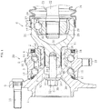
- FIG. 1 is a vertical sectional view for illustrating a state in which the wheel bearing and the constant velocity universal joint are assembled to each other.
- FIG. 2 is a vertical sectional view for illustrating a state before assembling the wheel bearing and the constant velocity universal joint of FIG. 1 to each other.
- a wheel bearing 20 mainly comprises a hub wheel 1 and an inner race 2, which are inner members, double-row rolling elements 3 and 4, an outer member 5, and cages 15 and 16.
- the wheel bearing 20 and the constant velocity universal joint 6 are assembled to each other to form a wheel bearing device.
- an outer side of a vehicle referred to as an outboard side (left side in the figures), and a middle side of the vehicle is referred to as an inboard side (right side in the figures).
- the hub wheel 1 has an inner raceway surface 7 on the outboard side formed on an outer peripheral surface thereof, and comprises a wheel mounting flange 9 for allowing a wheel (not shown) to be mounted thereto.
- Hub bolts 10 for fixing a wheel disc are equiangularly embedded in the wheel mounting flange 9.
- the inner race 2 is fitted to a small-diameter step portion 12 formed on an outer peripheral surface of the hub wheel 1 on the inboard side, and an inner raceway surface 8 on the inboard side is formed on an outer peripheral surface of the inner race 2.
- the inner race 2 is press-fitted with adequate interference for the purpose of preventing creep.
- the inner raceway surface 7 on the outboard side that is formed on the outer peripheral surface of the hub wheel 1 and the inner raceway surface 8 on the inboard side that is formed on the outer peripheral surface of the inner race 2 constitute double-row raceway surfaces.
- the inner race 2 is press-fitted to the small-diameter step portion 12 of the hub wheel 1, and the end portion of the small-diameter step portion 12 is crimped outward. As a result, the inner race 2 is retained by a crimped portion 11 and integrated with the hub wheel 1, to thereby apply preload to the bearing 20 for a wheel.
- the outer member 5 has, on its inner peripheral surface, double-row outer raceway surfaces 13 and 14 opposed to inner raceway surfaces 7 and 8 of the hub wheel 1 and the inner race 2.
- a vehicle-body mounting flange 19 of the outer member 5 is fixed to a knuckle extending from a suspension device (not shown) of a vehicle body, to thereby mount the wheel bearing 20 to the vehicle body.
- the bearing 20 for a wheel has a double-row angular ball bearing structure. Specifically, the rolling elements 3 and 4 are interposed between the inner raceway surfaces 7 and 8 formed on the outer peripheral surfaces of the hub wheel 1 and the inner race 2 and the outer raceway surfaces 13 and 14 formed on the inner peripheral surface of the outer race 5, and the rolling elements 3 and 4 in respective rows are equiangularly supported by cages 15 and 16.
- a pair of seals 17 and 18 for sealing annular spaces between the outer race 5 and the hub wheel 1 and between the outer race 5 and the inner race 2 so as to be held in sliding-contact with the outer peripheral surfaces of the hub wheel 1 and the inner race 2 are fitted to the inner diameter at both end portions of the outer race 5. Further, the seals 17 and 18 prevent leakage of grease filled inside and entrance of water and foreign matter from the outside.
- the constant velocity universal joint 6 comprises an outer joint member 24 provided at one end of an intermediate shaft 22 that constitutes a drive shaft 21, the outer joint member 24 having track grooves 23 formed in an inner peripheral surface thereof, an inner joint member 26 having track grooves 25 formed in an outer peripheral surface thereof so as to be opposed to the track grooves 23 of the outer joint member 24, torque transmission balls 27 (sometimes simply referred to as ball) built into spaces between the track grooves 23 of the outer joint member 24 and the track grooves 25 of the inner joint member 26, and a cage 28 interposed between the inner peripheral surface of the outer joint member 24 and the outer peripheral surface of the inner joint member 26 to retain the balls 27.
- torque transmission balls 27 sometimes simply referred to as ball
- the outer joint member 24 comprises a mouth section 29 that accommodates internal components such as the inner joint member 26, the balls 27, and the cage 28, and a stem section 30 that integrally extends from the mouth section 29 in an axial direction.
- An axial end of the intermediate shaft 22 is press-fitted to the inner joint member 26, and is coupled by spline fitting to allow torque transmission therebetween.
- a bellows-like boot 31 made of a resin is mounted between the outer joint member 24 of the constant velocity universal joint 6 and the intermediate shaft 22 to prevent leakage of a lubricant such as grease filled inside the joint, and to prevent entrance of foreign matter from outside the joint, thereby attaining a structure of closing an opening portion of the outer joint member 24 with the boot 31.
- a male spline 37 is formed on an outboard-side outer peripheral surface of the stem section 30 of the outer joint member 24, and a female spline 39 is formed on an outboard-side inner peripheral surface of a shaft hole 38 of the hub wheel 1.
- the male spline 37 of the stem section 30 of the outer joint member 24 is press-fitted to the female spline 39.
- the female spline 39 is an interference-defined spline, and has an interference "n" with respect to a circumferential side-wall portion 47 of the male spline 37.
- the interference-defined spline 39 corresponds to an interference-defined spline given in Description and Claims.
- interference-defined spline 39 A guide spline 44 is formed at an inboard-side end portion of the interference-defined spline 39.
- the guide spline 44 is configured to guide the male spline 37 at the time of starting press-fitting of the stem section 30.
- the guide spline 44 has such a spline shape that is formed so as to have the same phase as the interference-defined spline 39 and be larger than the male spline 37 of the stem section 30.
- An inner wall 43 is provided on an outboard side of the shaft hole 38 of the hub wheel 1, and has a bearing surface 36 and an insertion hole 35 for a bolt 32. Meanwhile, a female thread portion 33 is formed at an axial end of the stem section 30 of the outer joint member 24. Under a state in which the stem section 30 of the outer joint member 24 is inserted and fitted to the shaft hole 38 of the hub wheel 1, a male thread portion 34 of the bolt 32 is inserted into the insertion hole 35 of the inner wall 43 of the male thread portion 34. The male thread portion 34 is threadedly engaged with the female thread portion 33 of the stem section 30 of the outer joint member 24.
- the bolt 32 is fastened under a state in which a head portion 51 of the bolt 32 is locked to the bearing surface 36, thereby press-fitting the outer joint member 24 to the hub wheel 1 and finally fixing the wheel bearing 20 and the constant velocity universal joint 6 to each other.
- Medium carbon steel, as represented by S53C, for a mechanical structure is suitable for a material of the outer joint member 24 and the hub wheel 1.
- the male spline 37 of the stem section 30 is fitted to the guide spline 44 of the hub wheel 1.
- the male spline 37 of the stem section 30 can be guided so as to be reliably press-fitted to the interference-defined spline 39 of the hub wheel 1.
- stable press-fitting can be performed, thereby being capable of preventing center deviation or center inclination at the time of press-fitting.
- FIG. 3a is an enlarged main part vertical sectional view for illustrating a state before press-fitting the stem section of the outer joint member to the hub wheel of the wheel bearing.
- FIG. 3b is a transverse sectional view taken along the line A-A of FIG. 3a.
- FIG. 4a is an enlarged main part vertical sectional view for illustrating a state on the way of press-fitting the stem section of the outer joint member to the hub wheel of the wheel bearing.
- FIG. 4b is a transverse sectional view taken along the line B-B of FIG. 4a .
- FIG. 5a is an enlarged main part vertical sectional view for illustrating a state after press-fitting the stem section of the outer joint member to the hub wheel of the wheel bearing.
- FIG. 5b is a transverse sectional view taken along the line C-C of FIG. 5a .
- gaps "m” are defined between the male spline 37 and the guide spline 44 as illustrated in FIG. 3b .
- the male spline 37 can be easily fitted to the guide spline 44, and can be guides so as to be reliably press-fitted to the guide spline 44.
- the male spline 37 is press-fitted to the interference-defined spline 39.
- the interference-defined spline 39 has a circumferential dimension smaller than that of the male spline 37. Therefore, the interference-defined spline 39 has the interference "n” only with respect to the circumferential side-wall portion 47 of the male spline 37.
- a total interference 2n of the interferences "n" on both sides of tooth surfaces of the interferences spline is from about 10 ⁇ m to 50 pm.
- the interference-defined spline 39 has a radial dimension larger than that of the male spline 37.
- a gap "p" is defined between a part of the male spline 37 excluding the circumferential side-wall portions 47, that is, a radial distal end portion 48 of the male spline 37 and the interference-defined spline 39.
- the male spline 37 has a tooth shape having a trapezoidal cross sectional shape, but may have an involute tooth shape.
- the male spline 37 has a module falling within a range of from 0.3 to 0.75, which is set smaller than a module of a conventional spline having a module of equal to or more than 1.0.
- the male spline 37 have a surface hardness higher than a surface hardness of the interference-defined spline 39.
- a difference between the surface hardness of the male spline 37 and the surface hardness of the interference-defined spline 39 be equal to or more than 20 in unit of HRC.
- the circumferential side-wall portions 47 of the male spline 37 bite into the interference-defined spline 39 to slightly increase the inner diameter of the hub wheel 1, thereby allowing relative movement of the male spline 37 in the axial direction.
- the shaft hole 38 of the hub wheel 1 tends to return to an original diameter.
- the male spline 37 and the concave surfaces 40 of the interference-defined spline 39 are brought into close contact with each other in an entire fitting contact portion X, thereby being capable of rigidly connecting and integrating the outer joint member 24 and the hub wheel 1 to each other.
- the stem section 30 of the outer joint member 24 can be press-fitted to the shaft hole 38 of the hub wheel 1 with a drawing force given by the bolt 32 for fastening and fixing, thereby being capable of assembling the constant velocity universal joint 6 to the wheel bearing 20 in a simple manner.
- an operation of assembly to the vehicle body is improved, thereby being capable of preventing in advance damage on components at the time of assembly.
- a spline-processing method for a wheel bearing according to a first embodiment of the present invention is described with reference to FIG. 6 to FIGS. 12 .
- an integrated spline punch comprising an interference-defined spline forming surface and a guide spline forming surface is used, and a relief portion is formed on an outboard side of an inner peripheral surface which is configured to form the interference-defined spline of an intermediate component of the hub wheel, thereby achieving increase in accuracy of the interference-defined spline and simplification of a die and processing equipment.
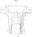
- FIG. 6 is a vertical sectional view for illustrating the intermediate component 1' of the hub wheel 1.
- the intermediate component 1' of the hub wheel 1 is obtained by subjecting a forged preform to machining such as turning or drilling to have a wheel mounting flange 9, an outboard-side inner raceway surface 7', a small-diameter step portion 12', the shaft hole 38, a spline-formation inner peripheral surface 50, a relief portion 52, the insertion hole 35, and hub bolt holes (not shown).
- the relief portion 52 has an inner diameter which is larger than an inner diameter of the spline-formation inner peripheral surface 50 with a suitable dimension. Details of an action of the relief portion 52 are described later.
- FIG. 7 is a side view for illustrating the integrated spline punch.
- FIG. 8a is a view for illustrating a transverse cross section of each of spline teeth of forming surfaces of the integrated spline punch.
- FIG. 8b is a front view of the spline forming surfaces of the integrated spline punch.
- FIG. 8c is a partial side view of the integrated spline punch.
- an integrated spline punch 80 comprises a cylindrical guide surface 81, which is formed at a distal end portion, an interference-defined spline forming surface 82, and a guide spline forming surface 83.
- the integrated spline punch 80 comprises a chamfered portion 84 and a chamfered portion 85.
- the chamfered portion 84 is formed at a connection portion between the cylindrical guide surface 81 and the interference-defined spline forming surface 82.
- the chamfered portion 85 is formed at a connection portion between the interference-defined spline forming surface 82 and the guide spline forming surface 83.
- the interference-defined spline forming surface 82 and the guide spline forming surface 83 match each other in phase.
- An inclination angle of each of the chamfered portions 84 and 85 is suitably set in consideration of, for example, a flow of material or suppression of an axial dimension. It is preferred that the chamfered portion 84 have an inclination angle of from about 20° to about 30°, and the chamfered portion 85 have an inclination angle of from about 2° to about 8°.
- the guide spline forming surface 83 has a spline tooth shape which is formed so as to be larger than a spline tooth shape of the interference-defined spline forming surface 82.
- the broken line on an inner side of the spline tooth shape of the guide spline forming surface 83 indicates the spline tooth shape of the interference-defined spline forming surface 82.
- FIG. 9a is a schematic view for illustrating a state in which the intermediate component of the hub wheel is set in a die.
- FIG. 9b is a schematic view for illustrating a state in which an upper punch is brought into abutment against the intermediate component of the hub wheel.
- FIG. 9c is a schematic view for illustrating a state in which the spline processing has been terminated.
- FIG. 9d is a schematic view for illustrating a state of removing the hub wheel. As illustrated in FIG. 9a to FIG.
- the main die to be used for the spline-processing method comprises an upper punch 90, a die 91, a base 92, the integrated spline punch 80, and a work-piece knockout 93.
- a compression spring 94 is incorporated between the die 91 and the base 92.
- the upper punch 90 retreats upward, and the die 91 is positioned at an upper end by a pressing force of the compression spring 94.
- the integrated spline punch 80 is fixed to the base 92.
- the work-piece knockout 93 retreats downward.
- the intermediate component 1' of the hub wheel 1 is set in the die 91.
- An outer peripheral surface of the intermediate component 1' is restricted by the die 91.
- the upper punch 90 advances downward to be brought into abutment against the wheel mounting flange 9 of the intermediate component 1'.
- the intermediate component 1' restricted by the die 91 is lowered.
- the interference-defined spline 39 and the guide spline 44 are formed on the spline-formation inner peripheral surface 50 of the intermediate component 1'.
- a spline-formed product 1" is obtained.
- the interference-defined spline 39 and the guide spline 44 can be formed by one stroke of pressing.
- the upper punch 90 retreats to an upper end, and the work-piece knockout 93 advances upward. Then, the spline-formed product 1" is removed from the die 91.
- FIG. 10 is an illustration of the spline-formed product 1" of the hub wheel 1.
- the integrated spline punch 80 is used, and the intermediate component 1' formed based on knowledge obtained in the course of development, which is described later, has the relief portion 52 having an inner diameter which is larger than an inner diameter of the spline-formation inner peripheral surface 50.
- the spline-formed product 1" has, on its inner periphery, the interference-defined spline 39 and the guide spline 44 having high accuracy.
- highly accurate phase matching between the interference-defined spline 39 and the guide spline 44 can be achieved.
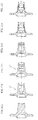
- FIGS. 11 are schematic illustrations of the processing step for the hub wheel to which the processing method for a wheel bearing according to this embodiment is applied.
- a preform is prepared in a forging step illustrated in FIG. 11a .
- the preform is subjected to turning to have, for example, an outer peripheral surface, an inner peripheral surface, and an insertion hole, thereby preparing the intermediate component 1'.
- the intermediate component 1' is subjected to the spline processing described above, thereby obtaining the spline-formed product 1".
- This spline processing step is based on the spline-processing method according to this embodiment.
- the spline-formed product 1" is subjected to turning to have, for example, a cylindrical outer peripheral surface and a small-diameter step portion.
- a heat treatment step illustrated in FIG. 11e a heat-treatment hardened layer is formed partially at a root of the wheel mounting flange, the inner raceway surface, the cylindrical outer peripheral surface, and the small-diameter step portion.
- a grinding step illustrated in FIG. 11f the root of the wheel mounting flange, the inner raceway surface, and the small-diameter step portion are subjected to grinding, thereby completing the hub wheel.
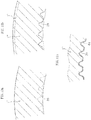
- FIG. 12a is a transverse sectional view for illustrating a state before processing.
- FIG. 12b is a transverse sectional view for illustrating a state after processing.
- FIG. 12c is a transverse sectional view of a guide spline portion.
- an outer diameter of the spline-formed product 1" is slightly increased as compared to an outer diameter of the intermediate component 1' indicated by the two-dot chain line. Such slight increase in outer diameter of the spline-formed product 1" as a whole can be dealt with the secondary turning of FIG. 11d described above.
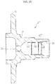
- a heat-treatment hardened layer is further formed on a radially outer side of the spline-formation inner peripheral surface of the intermediate component 1' of the hub wheel 1.
- the heat-treatment hardened layer is formed on the radially outer side of the spline-formation inner peripheral surface of the intermediate component of the hub wheel obtained based on the knowledge obtained in the course of development described later. In combination of both the features, quality and accuracy of the spline is further improved.
- a heat-treatment hardened layer H is formed in advance on the radially outer side of the spline-formation inner peripheral surface 50 of the intermediate component 1'.
- the heat-treatment hardened layer H extends from a root 9a of the wheel mounting flange to the inner raceway surface 7', the cylindrical outer peripheral surface 41, and a part of the small-diameter step portion 12'.
- the heat-treatment hardened layer H is illustrated in terms of a range of an overall hardened layer depth.
- the overall hardened layer depth is a range of hardening by the heat treatment to a hardness higher than a blank hardness given before heat treatment, and the blank hardened layer given before the heat treatment falls within a range of from about HRC10 to about HRC30.
- Other configurations of the intermediate component 1' are the same as those of the intermediate component 1' in the first embodiment. Therefore, parts having the same functions are denoted by the same reference symbols, and description thereof is omitted.
- the spline processing step in this embodiment is the same as that in the first embodiment, and hence contents of the spline processing step in the first embodiment is applied, and description thereof is omitted.
- FIGS. 14 are schematic illustrations of the processing step for the hub wheel to which the processing method for a wheel bearing according to this embodiment is applied.
- a preform is prepared in a forging step illustrated in FIG. 14a .
- the preform is subjected to turning to have, for example, an outer peripheral surface, an inner peripheral surface, and an insertion hole.
- the intermediate component 1' comprising the heat-treatment hardened layer formed on each of the root of the wheel mounting flange, the inner raceway surface, the cylindrical outer peripheral surface, and the small-diameter step portion is prepared.
- the intermediate component 1' having formed thereon the heat-treatment hardened layer is subjected to the spline processing, thereby obtaining the spline-formed product 1".
- This spline processing step is based on the spline-processing method according to this embodiment.
- the root of the wheel mounting flange of the spline-formed product 1", the inner raceway surface, and the small-diameter step portion are subjected to grinding, thereby completing the hub wheel.
- the heat treatment step is incorporated before the spline processing step, thereby shortening the processing step as compared to the first embodiment.
- FIG. 15 is a schematic view for illustrating the knowledge obtained in the course of development with regard to a flow of material.
- FIG. 16a is an illustration of the knowledge obtained in the course of development with regard to a state of processing of the spline, and is a transverse sectional view of each of three parts of the interference-defined spline in the axial direction.
- FIG. 16b is a front view of the spline forming surfaces of the integrated spline punch.
- FIG. 16c is a partial side view of the integrated spline punch.
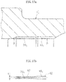
- FIG. 17a is a vertical sectional view of the intermediate component of the hub wheel.
- FIG. 17b is a sectional view of the interference-defined spline and the guide spline taken along the line D-D of FIG. 17a , when viewed in the direction indicated by the arrows.
- FIG. 18 is a collective illustration of the knowledge obtained in the course of development.
- the left half from the center line is a vertical sectional view of the intermediate component having no relief portion
- the right half from the center line is a vertical sectional view of the intermediate component having the relief portion and the heat-treatment hardened layer.
- an intermediate component 1' 1 comprising a straight shape without the relief portion as illustrated in the left half of FIG. 18 is prepared, and a test was conducted with regard to pressing of the splines with use of the integrated spline punch 80 comprising the interference-defined spline forming surface 82 and the guide spline forming surface 83.
- both ends of the interference-defined spline 39 1 in the axial direction are in contact with the interference-defined spline forming surface 82 of the integrated spline punch 80, but a center portion of the interference-defined spline 39 1 in the axial direction is formed in a state of being separated apart from the interference-defined spline forming surface 82 by a tooth gap "s".
- FIG. 17a and FIG. 17b illustration is given of a state of the spline teeth of the interference-defined spline 39 1 and the guide spline 44 1 in a tooth trace direction.
- a spline tooth width "t" at the center portion of the interference-defined spline 39 1 in the axial direction is formed so as to be smaller than a spline tooth width of the interference-defined spline forming surface 82 indicated by the two-dot chain line.
- the interferences "n” vary in the axial direction of the interference-defined spline 39 1 .
- hatching of the cross section of the spline tooth is omitted.
- the inventors of the present invention have arrived at the idea of forming, as illustrated in the right half of FIG. 18 , the relief portion 52 having an inner diameter larger than that of the spline-formation inner peripheral surface 50 on the outboard side of the spline-formation inner peripheral surface 50 of the intermediate component 1' of the hub wheel 1.
- the intermediate component 1' 1 having no relief portion as illustrated in the left half of FIG. 18 , when the pressing is performed with the integrated spline punch 80, as indicated by the arrows in the left half of FIG.
- the flow of the material given during formation of the splines is present not only on the rear side of the integrated spline punch 80, and a flow in a direction toward the distal end portion of the punch is also generated, thereby being capable of suppressing the deformation of the interference-defined spline 39 given during formation of the guide spline 44.
- the accuracy in formation of the interference-defined spline 39 is improved, thereby being capable of suppressing variation in tooth gap "s" of the interference-defined spline 39 and variation in the interferences "n".
- the inventors of the present invention have arrived at the idea of forming the heat-treatment hardened layer H on the radially outer side of the spline-formation inner peripheral surface 50 of the intermediate component 1' of the hub wheel 1 to thereby enhance stiffness of the intermediate component 1'. It has been verified that, when the integrated spline punch 80 is pressed into the intermediate component 1' in the stage of formation of the heat-treatment hardened layer H on the radially outer side of the intermediate component 1' of the spline-formation inner peripheral surface 50, the deformation of the interference-defined spline 39 in the axial direction in the barrel shape is alleviated, thereby being capable of performing processing with high accuracy.
- the integrated spline punch 80 when the integrated spline punch 80 is pressed into the intermediate component 1' having the heat-treatment hardened layer formed thereon to form the splines, the material flows in the axial direction toward the inboard side, with the result that cracks become more liable to occur on the radially outer side of the intermediate component 1'.
- the inner diameter of the blank is increased to reduce the cross-section reduction ratio in order to suppress the flow of the material as a countermeasure for the cracks, the cracks become less liable to occur on the radially outer side.
- burrs and chips are formed at the spline portions as in the case of cutting, with the result that the formation quality of the splines is liable to be degraded. Therefore, it was found that the range of processing conditions achieving high accuracy (cross-section reduction ratio) without causing cracks on the radially outer side is very narrow.
- Cross-section reduction ratio % sectional area before formation-sectional area after formation / sectional area before formation ⁇ 100
- the relief portion 52 of the intermediate component 1' of the hub wheel 1 is formed in the turning step.
- the relief portion 52 may be formed in the forging step for the preform of the hub wheel 1.
- the relief portion 52 may be formed after the heat treatment step.
- the present invention is not limited thereto, but is also applicable to a wheel bearing of the type in which a pair of inner races is press-fitted to the outer periphery of the hub wheel and the raceway surface 7 on the outboard side is formed on the outer periphery of one of the inner races, while the raceway surface 8 on the inboard side is formed on the outer periphery of the other of the inner races (referred to as "first and second generations").
Landscapes
- Engineering & Computer Science (AREA)
- General Engineering & Computer Science (AREA)
- Mechanical Engineering (AREA)
- Manufacturing & Machinery (AREA)
- Rolling Contact Bearings (AREA)
- Forging (AREA)
- Mounting Of Bearings Or Others (AREA)
Abstract
Description
- The present invention relates to a spline-processing method for a wheel bearing.
- As a bearing device for a wheel, for example, which rotatably supports a driving wheel (front wheel of a front-engine front-drive (FF) vehicle, rear wheel of a front-engine rear-drive (FR) vehicle, and all wheels of a four-wheel drive (4WD) vehicle) with respect to a suspension device for an automobile there is proposed a bearing device for a wheel, which is configured so that a hub wheel is separable from an outer joint member of a constant velocity universal joint to attain excellent maintainability (see, for example, Patent Document 1).
- The wheel bearing device described in
Patent Document 1 includes a wheel bearing including: an outer member having double-row outer raceway surfaces formed on an inner periphery thereof; an inner member including a hub wheel and an inner race, the inner member having double-row inner raceway surfaces formed on an outer periphery thereof so as to be opposed to the outer raceway surfaces; and double-row rolling elements interposed between the outer raceway surfaces of the outer member and the inner raceway surfaces of the inner member, the wheel bearing having a constant velocity universal joint separably coupled thereto with a screw fastening structure in which a stem section of an outer joint member of the constant velocity universal joint is fitted to an inner diameter surface of the hub wheel of the wheel bearing, in which a plurality of convex portions (male spline) being formed on the stem section of the outer joint member and extending in an axial direction are press-fitted to the hub wheel, which includes a plurality of concave portions formed thereon so as to have an interference with respect to the convex portions, and a shape of the convex portions is transferred to the hub wheel, to thereby provide a convex and concave fitting structure in which the convex portions and the concave portion are brought into close contact with each other at an entire fitting contact portion therebetween. - In the wheel bearing device described above, the screw fastening structure is formed of a female thread portion formed at an axial end of the stem section of the outer joint member and a bolt to be locked at a bearing surface of an inner wall of the hub wheel in a state of being threadedly engaged with the female thread portion.
- In the wheel bearing device described above, the female spline having the interference with respect to the male spline formed on the stem section of the outer joint member is formed in advance in the hub wheel. Therefore, a press-fitting load to be applied when the male spline and the female spline are brought into close contact with each other at an entire fitting contact portion therebetween can be reduced. Thus, there is an advantage in that, at the time of assembling a vehicle in an automobile manufacturer, the outer joint member can be press-fitted to the hub wheel with a force that is equal to or smaller than an axial force to be generated by fastening the bolt.
- The female spline of the hub wheel has hitherto been formed by broaching as cutting. Moreover, there has been proposed a technology of forming a female spline on a shaft inner diameter surface by pressing with high accuracy (Patent Document 2).
-
- Patent Document 1:
JP 2013-233842 A - Patent Document 2:
JP 2009-172663 A - However, in the case of the wheel bearing of
Patent Document 1, a bearing surface for a bolt configured to draw the outer joint member of the constant velocity universal joint to the hub wheel is formed on an inner wall of the hub wheel. Thus, a broaching tool cannot be completely drawn out, with the result that the broaching having hitherto been performed cannot be employed. - Moreover, in the wheel bearing described above, two stages of splines including a female spline and a guide spline are formed. The female spline has an inner peripheral surface configured to receive the stem section of the outer joint member to be press-fitted thereto. The guide spline is formed at one end of the female spline and serves as an insertion guide configured to guide the press-fitting of the stem section. Formation of such two stages of splines is difficult for a system of drawing out a spline mandrel as in
Patent Document 2. - Further, it is required that phases of the female spline and the guide spline match. However, a module (reference circle diameter/the number of teeth) of the spline is small, and hence it was found that there is a difficulty in matching phases of both splines in two-step formation of forming the female spline and separately forming the guide spline thereafter.
- In addition, it was also found that, in order to satisfy an interference (press-fitting interference) of the female spline in the entire fitting contact portion between the hub wheel and the stem section of the outer joint member, it is required that the female spline be increased in accuracy.
- In view of the problems described above, the present invention has an object to provide a spline-processing method for a wheel bearing, which is capable of increasing an accuracy of a spline and simplifying a die and processing equipment.
- As a result of extensive studies conducted to achieve the object described above, the inventors of the present invention have arrived at the present invention based on an idea of using an integrated spline punch having a female spline (spline with interference) forming surface and a guide spline forming surface, and an idea of contriving a shape of an intermediate component of a hub wheel serving as an inner member.
- As a technological measure to achieve the above-mentioned object, the present invention provides a spline-processing method for a wheel bearing comprising: an outer member having double-row outer raceway surfaces formed on an inner peripheral surface thereof; an inner member having double-row inner raceway surfaces formed on an outer peripheral surface thereof so as to be opposed to the double-row outer raceway surfaces; and double-row rolling elements interposed between the raceway surfaces of the double-row outer raceway surfaces of the outer member and the double-row inner raceway surfaces of the inner member; and a cage configured to retain the double-row rolling elements, the inner member having an interference-defined spline formed on an inner periphery thereof, the interference-defined spline having a guide spline formed at an inboard-side end portion thereof, wherein an intermediate component of the inner member comprises: a spline-formation inner peripheral surface comprising the interference-defined spline and the guide spline formed thereon; and a relief portion, which is formed on an outboard side with respect to the spline-formation inner peripheral surface, and has a diameter larger than that of the spline-formation inner peripheral surface, wherein a punch to be used for the spline processing comprises an integrated spline punch comprising: an interference-defined spline forming surface configured to form the interference-defined spline; and a guide spline forming surface configured to form the guide spline, and wherein the spline-formation inner peripheral surface is formed by pressing with the integrated spline punch to form the interference-defined spline and the guide spline.
- With the configuration described above, a spline-processing method for a wheel bearing which is capable of increasing an accuracy of a spline and simplifying a die and a processing equipment can be achieved. Moreover, highly accurate phase matching between the interference-defined spline and the guide spline can be achieved.
- The interference-defined spline forming surface and the guide spline forming surface of the integrated spline punch described above have a chamfered portion formed at a connection portion therebetween. With this, an accuracy of the interference-defined spline and the guide spline in the axial direction is further improved, thereby improving a lifetime of the die.
- The intermediate component of the inner member has a heat-treatment hardened layer on an outer diameter surface thereof. With this, quality and accuracy of the spline is further improved.
- According to one embodiment of the present invention, there can be provided the spline-processing method for the wheel bearing, which is capable of increasing the accuracy of the spline and simplifying the die and processing equipment.
-
-
FIG. 1 is a vertical sectional view for illustrating a state in which a wheel bearing and a constant velocity universal joint are assembled to each other based on a spline-processing method for a wheel bearing according to an embodiment of the present invention. -
FIG. 2 is a vertical sectional view for illustrating a state before assembling the wheel bearing and the constant velocity universal joint ofFIG. 1 to each other. -
FIG. 3a is an enlarged main part vertical sectional view for illustrating a state before press-fitting a stem section of an outer joint member to the hub wheel of the wheel bearing. -
FIG. 3b is a transverse sectional view taken along the line A-A ofFIG. 3a . -
FIG. 4a is an enlarged main part vertical sectional view for illustrating a state on the way of press-fitting the stem section of the outer joint member to the hub wheel of the wheel bearing. -
FIG. 4b is a transverse sectional view taken along the line B-B ofFIG. 4a . -
FIG. 5a is an enlarged main part vertical sectional view for illustrating a state after press-fitting the stem section of the outer joint member to the hub wheel of the wheel bearing. -
FIG. 5b is a transverse sectional view taken along the line C-C ofFIG. 5a . -
FIG. 6 is a vertical sectional view for illustrating an intermediate component of a hub wheel in a spline-processing method for a wheel bearing according to a first embodiment of the present invention. -
FIG. 7 is a side view for illustrating an integrated spline punch. -
FIG. 8a is a view for illustrating a transverse cross section of each of spline teeth of forming surfaces of the integrated spline punch ofFIG. 7 . -
FIG. 8b is a front view of the spline forming surfaces of the integrated spline punch ofFIG. 7 . -
FIG. 8c is a partial side view of the integrated spline punch ofFIG. 7 . -
FIG. 9a is a schematic view for illustrating a state in which the intermediate component of the hub wheel is set in a die in the spline-processing method for a wheel bearing according to the first embodiment of the present invention. -
FIG. 9b is a schematic view for illustrating a state in which an upper punch is held in abutment against the intermediate component of the hub wheel in the spline-processing method for a wheel bearing according to the first embodiment of the present invention. -
FIG. 9c is a schematic view for illustrating a state in which spline processing has been terminated in the spline-processing method for a wheel bearing according to the first embodiment of the present invention. -
FIG. 9d is a schematic view for illustrating a state of removing the hub wheel in the spline-processing method for a wheel bearing according to the first embodiment of the present invention. -
FIG. 10 is a vertical sectional view for illustrating the hub wheel after the spline processing. -
FIG. 11a is a schematic view for illustrating a blank in a processing step for the hub wheel. -
FIG. 11b is a schematic view for illustrating primary turning in the processing step for the hub wheel. -
FIG. 11c is a schematic view for illustrating spline processing in the processing step for the hub wheel. -
FIG. 11d is a schematic view for illustrating secondary turning in the processing step for the hub wheel. -
FIG. 11e is a schematic view of heat treatment in the processing step for the hub wheel. -
FIG. 11f is a schematic view of grinding in the processing step for the hub wheel. -
FIG. 12a is a transverse sectional view for illustrating a state before processing the spline. -
FIG. 12b is a transverse sectional view for illustrating a state after processing the spline. -
FIG. 12c is a transverse sectional view of a guide spline portion. -
FIG. 13 is a vertical sectional view for illustrating an intermediate component of a hub wheel in a spline-processing method for a wheel bearing according to a second embodiment of the present invention. -
FIG. 14a is a schematic view of a blank in a processing step for a hub wheel. -
FIG. 14b is a schematic view for illustrating turning in the processing step for the hub wheel. -
FIG. 14c is a schematic view for illustrating heat treatment in the processing step for the hub wheel. -
FIG. 14d is a schematic view for illustrating spline processing in the processing step for the hub wheel. -
FIG. 14e is a schematic view for illustrating grinding in the processing step for the hub wheel. -
FIG. 15 is a schematic view for illustrating knowledge obtained in the course of development with regard to a flow of material. -
FIG. 16a is an illustration of knowledge obtained in the course of development with regard to a state of processing of the spline, and is a transverse sectional view of each of three parts of an interference-defined spline in an axial direction. -
FIG. 16b is an illustration of knowledge obtained in the course of development with regard to a state of processing of the spline, and is a front view of the spline forming surfaces of the integrated spline punch. -
FIG. 16c is an illustration of knowledge obtained in the course of development with regard to a state of processing of the spline, and is a partial side view of the integrated spline punch. -
FIG. 17a is an illustration of knowledge obtained in the course of development with regard to a state of forming the spline, and is a vertical sectional view of the intermediate component of the hub wheel. -
FIG. 17b is a sectional view of the interference-defined spline and the guide spline taken along the line D-D ofFIG. 17a , when viewed in the direction indicated by the arrows. -
FIG. 18 is an explanatory view for collectively illustrating knowledge obtained in the course of development. - Prior to description of a spline-processing method for a wheel bearing according to a first embodiment of the present invention, description is made of a wheel bearing to be obtained by the spline-processing method and a constant velocity universal joint assembled to be assembled to the wheel bearing are described with reference to
FIG. 1 to FIG. 5 .FIG. 1 is a vertical sectional view for illustrating a state in which the wheel bearing and the constant velocity universal joint are assembled to each other.FIG. 2 is a vertical sectional view for illustrating a state before assembling the wheel bearing and the constant velocity universal joint ofFIG. 1 to each other. - As illustrated in
FIG. 1 andFIG. 2 , a wheel bearing 20 mainly comprises ahub wheel 1 and aninner race 2, which are inner members, double-row rolling elements outer member 5, andcages wheel bearing 20 and the constant velocityuniversal joint 6 are assembled to each other to form a wheel bearing device. Note that, in the following description, an outer side of a vehicle referred to as an outboard side (left side in the figures), and a middle side of the vehicle is referred to as an inboard side (right side in the figures). - The
hub wheel 1 has aninner raceway surface 7 on the outboard side formed on an outer peripheral surface thereof, and comprises awheel mounting flange 9 for allowing a wheel (not shown) to be mounted thereto.Hub bolts 10 for fixing a wheel disc are equiangularly embedded in thewheel mounting flange 9. Theinner race 2 is fitted to a small-diameter step portion 12 formed on an outer peripheral surface of thehub wheel 1 on the inboard side, and aninner raceway surface 8 on the inboard side is formed on an outer peripheral surface of theinner race 2. - The
inner race 2 is press-fitted with adequate interference for the purpose of preventing creep. Theinner raceway surface 7 on the outboard side that is formed on the outer peripheral surface of thehub wheel 1 and theinner raceway surface 8 on the inboard side that is formed on the outer peripheral surface of theinner race 2 constitute double-row raceway surfaces. Theinner race 2 is press-fitted to the small-diameter step portion 12 of thehub wheel 1, and the end portion of the small-diameter step portion 12 is crimped outward. As a result, theinner race 2 is retained by a crimpedportion 11 and integrated with thehub wheel 1, to thereby apply preload to thebearing 20 for a wheel. - The
outer member 5 has, on its inner peripheral surface, double-row outer raceway surfaces 13 and 14 opposed toinner raceway surfaces hub wheel 1 and theinner race 2. A vehicle-body mounting flange 19 of theouter member 5 is fixed to a knuckle extending from a suspension device (not shown) of a vehicle body, to thereby mount the wheel bearing 20 to the vehicle body. - The bearing 20 for a wheel has a double-row angular ball bearing structure. Specifically, the rolling
elements inner raceway surfaces hub wheel 1 and theinner race 2 and the outer raceway surfaces 13 and 14 formed on the inner peripheral surface of theouter race 5, and the rollingelements cages - At opening portions on both ends of the
bearing 20 for a wheel, a pair ofseals outer race 5 and thehub wheel 1 and between theouter race 5 and theinner race 2 so as to be held in sliding-contact with the outer peripheral surfaces of thehub wheel 1 and theinner race 2 are fitted to the inner diameter at both end portions of theouter race 5. Further, theseals - The constant velocity
universal joint 6 comprises an outerjoint member 24 provided at one end of anintermediate shaft 22 that constitutes adrive shaft 21, the outerjoint member 24 havingtrack grooves 23 formed in an inner peripheral surface thereof, an innerjoint member 26 havingtrack grooves 25 formed in an outer peripheral surface thereof so as to be opposed to thetrack grooves 23 of the outerjoint member 24, torque transmission balls 27 (sometimes simply referred to as ball) built into spaces between thetrack grooves 23 of the outerjoint member 24 and thetrack grooves 25 of the innerjoint member 26, and acage 28 interposed between the inner peripheral surface of the outerjoint member 24 and the outer peripheral surface of the innerjoint member 26 to retain theballs 27. - The outer
joint member 24 comprises amouth section 29 that accommodates internal components such as the innerjoint member 26, theballs 27, and thecage 28, and astem section 30 that integrally extends from themouth section 29 in an axial direction. An axial end of theintermediate shaft 22 is press-fitted to the innerjoint member 26, and is coupled by spline fitting to allow torque transmission therebetween. - A bellows-
like boot 31 made of a resin is mounted between the outerjoint member 24 of the constant velocityuniversal joint 6 and theintermediate shaft 22 to prevent leakage of a lubricant such as grease filled inside the joint, and to prevent entrance of foreign matter from outside the joint, thereby attaining a structure of closing an opening portion of the outerjoint member 24 with theboot 31. - As illustrated in
FIG. 2 , amale spline 37 is formed on an outboard-side outer peripheral surface of thestem section 30 of the outerjoint member 24, and afemale spline 39 is formed on an outboard-side inner peripheral surface of ashaft hole 38 of thehub wheel 1. Themale spline 37 of thestem section 30 of the outerjoint member 24 is press-fitted to thefemale spline 39. Thefemale spline 39 is an interference-defined spline, and has an interference "n" with respect to a circumferential side-wall portion 47 of themale spline 37. The interference-definedspline 39 corresponds to an interference-defined spline given in Description and Claims. In the following description, it is referred to as "interference-definedspline 39". Aguide spline 44 is formed at an inboard-side end portion of the interference-definedspline 39. Theguide spline 44 is configured to guide themale spline 37 at the time of starting press-fitting of thestem section 30. Theguide spline 44 has such a spline shape that is formed so as to have the same phase as the interference-definedspline 39 and be larger than themale spline 37 of thestem section 30. - An
inner wall 43 is provided on an outboard side of theshaft hole 38 of thehub wheel 1, and has a bearingsurface 36 and aninsertion hole 35 for abolt 32. Meanwhile, afemale thread portion 33 is formed at an axial end of thestem section 30 of the outerjoint member 24. Under a state in which thestem section 30 of the outerjoint member 24 is inserted and fitted to theshaft hole 38 of thehub wheel 1, amale thread portion 34 of thebolt 32 is inserted into theinsertion hole 35 of theinner wall 43 of themale thread portion 34. Themale thread portion 34 is threadedly engaged with thefemale thread portion 33 of thestem section 30 of the outerjoint member 24. Thebolt 32 is fastened under a state in which ahead portion 51 of thebolt 32 is locked to the bearingsurface 36, thereby press-fitting the outerjoint member 24 to thehub wheel 1 and finally fixing thewheel bearing 20 and the constant velocityuniversal joint 6 to each other. Medium carbon steel, as represented by S53C, for a mechanical structure is suitable for a material of the outerjoint member 24 and thehub wheel 1. - When the
stem section 30 of the outerjoint member 24 is inserted and fitted to theshaft hole 38 of thehub wheel 1 of thestem section 30, themale spline 37 of thestem section 30 is fitted to theguide spline 44 of thehub wheel 1. Thus, themale spline 37 of thestem section 30 can be guided so as to be reliably press-fitted to the interference-definedspline 39 of thehub wheel 1. Thus, stable press-fitting can be performed, thereby being capable of preventing center deviation or center inclination at the time of press-fitting. - Details of the course of press-fitting the stem section of the outer joint member to the hub wheel of the wheel bearing are described with reference to
FIGS. 3 to FIGS. 5 .FIG. 3a is an enlarged main part vertical sectional view for illustrating a state before press-fitting the stem section of the outer joint member to the hub wheel of the wheel bearing.FIG. 3b is a transverse sectional view taken along the line A-A ofFIG. 3a. FIG. 4a is an enlarged main part vertical sectional view for illustrating a state on the way of press-fitting the stem section of the outer joint member to the hub wheel of the wheel bearing.FIG. 4b is a transverse sectional view taken along the line B-B ofFIG. 4a .FIG. 5a is an enlarged main part vertical sectional view for illustrating a state after press-fitting the stem section of the outer joint member to the hub wheel of the wheel bearing.FIG. 5b is a transverse sectional view taken along the line C-C ofFIG. 5a . - Under a state in which a distal end portion of the
male spline 37 of thestem section 30 is fitted to theguide spline 44 as illustrated inFIG. 3a , gaps "m" are defined between themale spline 37 and theguide spline 44 as illustrated inFIG. 3b . With the presence of the gap "m", themale spline 37 can be easily fitted to theguide spline 44, and can be guides so as to be reliably press-fitted to theguide spline 44. - Next, as illustrated in
FIG. 4a , themale spline 37 is press-fitted to the interference-definedspline 39. As illustrated inFIG. 4b , the interference-definedspline 39 has a circumferential dimension smaller than that of themale spline 37. Therefore, the interference-definedspline 39 has the interference "n" only with respect to the circumferential side-wall portion 47 of themale spline 37. A total interference 2n of the interferences "n" on both sides of tooth surfaces of the interferences spline is from about 10 µm to 50 pm. Moreover, the interference-definedspline 39 has a radial dimension larger than that of themale spline 37. Therefore, a gap "p" is defined between a part of themale spline 37 excluding the circumferential side-wall portions 47, that is, a radialdistal end portion 48 of themale spline 37 and the interference-definedspline 39. Themale spline 37 has a tooth shape having a trapezoidal cross sectional shape, but may have an involute tooth shape. Themale spline 37 has a module falling within a range of from 0.3 to 0.75, which is set smaller than a module of a conventional spline having a module of equal to or more than 1.0. - As illustrated in
FIG. 5a and FIG. 5b , when thestem section 30 is to be press-fitted to theshaft hole 38 of thehub wheel 1, a surface of the interference-definedspline 39 is cut extremely slightly with the circumferential side-wall portions 47 of themale spline 37, and along with extremely slight plastic deformation or elastic deformation, the shape of the circumferential side-wall portions 47 of themale spline 37 is transferred to the interference-definedspline 39, thereby formingconcave surfaces 40. As illustrated inFIG. 5a , a protrudingpart 45 formed by the transfer described above is retained in anaccommodation portion 46. Therefore, removal of the protrudingpart 45 is not required, thereby being capable of achieving reduction in the number of working steps, improvement in operability, and cost reduction. It is preferred that themale spline 37 have a surface hardness higher than a surface hardness of the interference-definedspline 39. For example, it is suitable to set a difference between the surface hardness of themale spline 37 and the surface hardness of the interference-definedspline 39 be equal to or more than 20 in unit of HRC. Moreover, it is suitable to set the surface hardness of themale spline 37 so as to fall within a range of from HRC50 to HRC65, and set the surface hardness of the interference-definedspline 39 so as to fall within a range of from HRC10 to HRC30. - At the time of press-fitting, the circumferential side-
wall portions 47 of themale spline 37 bite into the interference-definedspline 39 to slightly increase the inner diameter of thehub wheel 1, thereby allowing relative movement of themale spline 37 in the axial direction. When the relative movement of themale spline 37 in the axial direction is stopped, theshaft hole 38 of thehub wheel 1 tends to return to an original diameter. With this, themale spline 37 and theconcave surfaces 40 of the interference-definedspline 39 are brought into close contact with each other in an entire fitting contact portion X, thereby being capable of rigidly connecting and integrating the outerjoint member 24 and thehub wheel 1 to each other. - With the press-fitting state as described above, a large press-fitting load is not required. Therefore, at the time of assembly of a vehicle in an automobile manufacturer, after the wheel bearing 20 is mounted to a knuckle extending from a suspension device of a vehicle body, the
stem section 30 of the outerjoint member 24 can be press-fitted to theshaft hole 38 of thehub wheel 1 with a drawing force given by thebolt 32 for fastening and fixing, thereby being capable of assembling the constant velocityuniversal joint 6 to the wheel bearing 20 in a simple manner. As a result, an operation of assembly to the vehicle body is improved, thereby being capable of preventing in advance damage on components at the time of assembly. - The overall configuration of the wheel bearing and the constant velocity universal joint is as described above. Next, a spline-processing method for a wheel bearing according to a first embodiment of the present invention is described with reference to
FIG. 6 to FIGS. 12 . Briefly, in the spline-processing method for a wheel bearing according to this embodiment, an integrated spline punch comprising an interference-defined spline forming surface and a guide spline forming surface is used, and a relief portion is formed on an outboard side of an inner peripheral surface which is configured to form the interference-defined spline of an intermediate component of the hub wheel, thereby achieving increase in accuracy of the interference-defined spline and simplification of a die and processing equipment. - First, with reference to
FIG. 6 , description is made of an intermediate component 1' of thehub wheel 1.FIG. 6 is a vertical sectional view for illustrating the intermediate component 1' of thehub wheel 1. The intermediate component 1' of thehub wheel 1 is obtained by subjecting a forged preform to machining such as turning or drilling to have awheel mounting flange 9, an outboard-side inner raceway surface 7', a small-diameter step portion 12', theshaft hole 38, a spline-formation innerperipheral surface 50, arelief portion 52, theinsertion hole 35, and hub bolt holes (not shown). Therelief portion 52 has an inner diameter which is larger than an inner diameter of the spline-formation innerperipheral surface 50 with a suitable dimension. Details of an action of therelief portion 52 are described later. - Next, with reference to
FIG. 7 andFIG. 8 , description is made of the integrated spline punch to be used for the spline processing.FIG. 7 is a side view for illustrating the integrated spline punch.FIG. 8a is a view for illustrating a transverse cross section of each of spline teeth of forming surfaces of the integrated spline punch.FIG. 8b is a front view of the spline forming surfaces of the integrated spline punch.FIG. 8c is a partial side view of the integrated spline punch. As illustrated inFIG. 7 , anintegrated spline punch 80 comprises acylindrical guide surface 81, which is formed at a distal end portion, an interference-definedspline forming surface 82, and a guidespline forming surface 83. - As illustrated in
FIG. 8b and FIG. 8c , theintegrated spline punch 80 comprises a chamferedportion 84 and a chamferedportion 85. The chamferedportion 84 is formed at a connection portion between thecylindrical guide surface 81 and the interference-definedspline forming surface 82. The chamferedportion 85 is formed at a connection portion between the interference-definedspline forming surface 82 and the guidespline forming surface 83. The interference-definedspline forming surface 82 and the guidespline forming surface 83 match each other in phase. An inclination angle of each of the chamferedportions portion 84 have an inclination angle of from about 20° to about 30°, and the chamferedportion 85 have an inclination angle of from about 2° to about 8°. - As illustrated in
FIG. 8a , the guidespline forming surface 83 has a spline tooth shape which is formed so as to be larger than a spline tooth shape of the interference-definedspline forming surface 82. The broken line on an inner side of the spline tooth shape of the guidespline forming surface 83 indicates the spline tooth shape of the interference-definedspline forming surface 82. With this, the gap "m" described above with reference toFIG. 3b is secured. InFIG. 8a , hatching on the cross section is omitted for ease of viewing the drawing. - Next, with reference to
FIGS. 9 , description is made of the processing step for the splines.FIG. 9a is a schematic view for illustrating a state in which the intermediate component of the hub wheel is set in a die.FIG. 9b is a schematic view for illustrating a state in which an upper punch is brought into abutment against the intermediate component of the hub wheel.FIG. 9c is a schematic view for illustrating a state in which the spline processing has been terminated.FIG. 9d is a schematic view for illustrating a state of removing the hub wheel. As illustrated inFIG. 9a to FIG. 9d , the main die to be used for the spline-processing method comprises anupper punch 90, adie 91, abase 92, theintegrated spline punch 80, and a work-piece knockout 93. Acompression spring 94 is incorporated between the die 91 and thebase 92. As described above, the spline-processing method according to this embodiment is capable of achieving a simple die structure and a simple equipment structure. - As illustrated in
FIG. 9a , theupper punch 90 retreats upward, and thedie 91 is positioned at an upper end by a pressing force of thecompression spring 94. Theintegrated spline punch 80 is fixed to thebase 92. The work-piece knockout 93 retreats downward. In this state, the intermediate component 1' of thehub wheel 1 is set in thedie 91. An outer peripheral surface of the intermediate component 1' is restricted by thedie 91. - As illustrated in
FIG. 9b , theupper punch 90 advances downward to be brought into abutment against thewheel mounting flange 9 of the intermediate component 1'. As theupper punch 90 further advances, as illustrated inFIG. 9c , the intermediate component 1' restricted by thedie 91 is lowered. With this, the interference-definedspline 39 and theguide spline 44 are formed on the spline-formation innerperipheral surface 50 of the intermediate component 1'. As a result, a spline-formedproduct 1" is obtained. As described above, the interference-definedspline 39 and theguide spline 44 can be formed by one stroke of pressing. - After formation of the interference-defined
spline 39 and theguide spline 44 is terminated, as illustrated inFIG. 9d , theupper punch 90 retreats to an upper end, and the work-piece knockout 93 advances upward. Then, the spline-formedproduct 1" is removed from thedie 91. -
FIG. 10 is an illustration of the spline-formedproduct 1" of thehub wheel 1. In this embodiment, theintegrated spline punch 80 is used, and the intermediate component 1' formed based on knowledge obtained in the course of development, which is described later, has therelief portion 52 having an inner diameter which is larger than an inner diameter of the spline-formation innerperipheral surface 50. With this, the spline-formedproduct 1" has, on its inner periphery, the interference-definedspline 39 and theguide spline 44 having high accuracy. In addition, with the use of theintegrated spline punch 80, highly accurate phase matching between the interference-definedspline 39 and theguide spline 44 can be achieved. -
FIGS. 11 are schematic illustrations of the processing step for the hub wheel to which the processing method for a wheel bearing according to this embodiment is applied. First, a preform is prepared in a forging step illustrated inFIG. 11a . After that, in a primary turning step illustrated inFIG. 11b , the preform is subjected to turning to have, for example, an outer peripheral surface, an inner peripheral surface, and an insertion hole, thereby preparing the intermediate component 1'. Next, in the spline processing step illustrated inFIG. 11c , the intermediate component 1' is subjected to the spline processing described above, thereby obtaining the spline-formedproduct 1". This spline processing step is based on the spline-processing method according to this embodiment. In a secondary turning step illustrated inFIG. 11d , the spline-formedproduct 1" is subjected to turning to have, for example, a cylindrical outer peripheral surface and a small-diameter step portion. After that, in a heat treatment step illustrated inFIG. 11e , a heat-treatment hardened layer is formed partially at a root of the wheel mounting flange, the inner raceway surface, the cylindrical outer peripheral surface, and the small-diameter step portion. Finally, in a grinding step illustrated inFIG. 11f , the root of the wheel mounting flange, the inner raceway surface, and the small-diameter step portion are subjected to grinding, thereby completing the hub wheel. - In the spline processing described above, in relation to a cross-section reduction ratio involved in formation of the splines, a diameter of the outer peripheral surface of the spline-formed product is slightly increased as a whole. Such state is illustrated in
FIGS. 12. FIG. 12a is a transverse sectional view for illustrating a state before processing.FIG. 12b is a transverse sectional view for illustrating a state after processing.FIG. 12c is a transverse sectional view of a guide spline portion. When the interference-definedspline 39 indicated by the broken line is formed on the intermediate component 1' illustrated inFIG. 12a , as illustrated inFIG. 12b , based on the cross-section reduction ratio, an outer diameter of the spline-formedproduct 1" is slightly increased as compared to an outer diameter of the intermediate component 1' indicated by the two-dot chain line. Such slight increase in outer diameter of the spline-formedproduct 1" as a whole can be dealt with the secondary turning ofFIG. 11d described above. - Next, with reference to
FIG. 13 andFIGS. 14 , description is made of a spline-processing method for a wheel bearing according to a second embodiment of the present invention. In this embodiment, as compared to the first embodiment, a heat-treatment hardened layer is further formed on a radially outer side of the spline-formation inner peripheral surface of the intermediate component 1' of thehub wheel 1. In addition to the use of the integrated spline punch and formation of the relief portion having an inner diameter larger than that of the spline-formation inner peripheral surface, the heat-treatment hardened layer is formed on the radially outer side of the spline-formation inner peripheral surface of the intermediate component of the hub wheel obtained based on the knowledge obtained in the course of development described later. In combination of both the features, quality and accuracy of the spline is further improved. - With reference to
FIG. 13 , description is made of the intermediate component 1' of thehub wheel 1 to be used for the spline-processing method for a wheel bearing according to this embodiment. A heat-treatment hardened layer H is formed in advance on the radially outer side of the spline-formation innerperipheral surface 50 of the intermediate component 1'. The heat-treatment hardened layer H extends from aroot 9a of the wheel mounting flange to the inner raceway surface 7', the cylindrical outerperipheral surface 41, and a part of the small-diameter step portion 12'. The heat-treatment hardened layer H is illustrated in terms of a range of an overall hardened layer depth. The overall hardened layer depth is a range of hardening by the heat treatment to a hardness higher than a blank hardness given before heat treatment, and the blank hardened layer given before the heat treatment falls within a range of from about HRC10 to about HRC30. Other configurations of the intermediate component 1' are the same as those of the intermediate component 1' in the first embodiment. Therefore, parts having the same functions are denoted by the same reference symbols, and description thereof is omitted. Moreover, the spline processing step in this embodiment is the same as that in the first embodiment, and hence contents of the spline processing step in the first embodiment is applied, and description thereof is omitted. -
FIGS. 14 are schematic illustrations of the processing step for the hub wheel to which the processing method for a wheel bearing according to this embodiment is applied. First, a preform is prepared in a forging step illustrated inFIG. 14a . Next, in a primary turning step illustrated inFIG. 14b , the preform is subjected to turning to have, for example, an outer peripheral surface, an inner peripheral surface, and an insertion hole. After that, in a heat treatment step illustrated inFIG. 14c , the intermediate component 1' comprising the heat-treatment hardened layer formed on each of the root of the wheel mounting flange, the inner raceway surface, the cylindrical outer peripheral surface, and the small-diameter step portion is prepared. In the spline processing step illustrated inFIG. 14d , the intermediate component 1' having formed thereon the heat-treatment hardened layer is subjected to the spline processing, thereby obtaining the spline-formedproduct 1". This spline processing step is based on the spline-processing method according to this embodiment. Finally, in a grinding step illustrated inFIG. 14e , the root of the wheel mounting flange of the spline-formedproduct 1", the inner raceway surface, and the small-diameter step portion are subjected to grinding, thereby completing the hub wheel. The heat treatment step is incorporated before the spline processing step, thereby shortening the processing step as compared to the first embodiment. - Finally, the knowledge obtained in the course of development to the arrival at the first and second embodiments of the present invention is collectively described with reference to
FIG. 15 to FIG. 18 .FIG. 15 is a schematic view for illustrating the knowledge obtained in the course of development with regard to a flow of material.FIG. 16a is an illustration of the knowledge obtained in the course of development with regard to a state of processing of the spline, and is a transverse sectional view of each of three parts of the interference-defined spline in the axial direction.FIG. 16b is a front view of the spline forming surfaces of the integrated spline punch.FIG. 16c is a partial side view of the integrated spline punch.FIG. 17a is a vertical sectional view of the intermediate component of the hub wheel.FIG. 17b is a sectional view of the interference-defined spline and the guide spline taken along the line D-D ofFIG. 17a , when viewed in the direction indicated by the arrows.FIG. 18 is a collective illustration of the knowledge obtained in the course of development. The left half from the center line is a vertical sectional view of the intermediate component having no relief portion, and the right half from the center line is a vertical sectional view of the intermediate component having the relief portion and the heat-treatment hardened layer. - First, an intermediate component 1'1 comprising a straight shape without the relief portion as illustrated in the left half of
FIG. 18 is prepared, and a test was conducted with regard to pressing of the splines with use of theintegrated spline punch 80 comprising the interference-definedspline forming surface 82 and the guidespline forming surface 83. - However, when the
integrated spline punch 80 is used, with the flow of material indicated by the arrows inFIG. 15 , at the time of formation of aguide spline 441 portion, a material is pressed toward a side of an interference-definedspline 391 having been formed. Therefore, the shape of the interference-definedspline 391 is lost. As a result, as illustrated inFIG. 15 , the interference-definedspline 391 is formed into a barrel shape, which may cause variation in the interferences "n" illustrated inFIG. 4b . Accordingly, the following fact was found. That is, at the time of fitting between of thestem section 30 to thehub wheel 1, when the interferences are given in the entire fitting contact portion X, the press-fitting load is increased by the drawing force of the bolt 32 (seeFIG. 2 ), with the result that the product function is not satisfied. - With reference to
FIG. 16 andFIG. 17 , description is made of the state of the barrel shape of the interference-definedspline 391. As illustrated inFIGS. 16 , both ends of the interference-definedspline 391 in the axial direction are in contact with the interference-definedspline forming surface 82 of theintegrated spline punch 80, but a center portion of the interference-definedspline 391 in the axial direction is formed in a state of being separated apart from the interference-definedspline forming surface 82 by a tooth gap "s". - Further, in
FIG. 17a and FIG. 17b , illustration is given of a state of the spline teeth of the interference-definedspline 391 and theguide spline 441 in a tooth trace direction. As illustrated inFIG. 17b , a spline tooth width "t" at the center portion of the interference-definedspline 391 in the axial direction is formed so as to be smaller than a spline tooth width of the interference-definedspline forming surface 82 indicated by the two-dot chain line. As a result, the interferences "n" vary in the axial direction of the interference-definedspline 391. InFIG. 17b , hatching of the cross section of the spline tooth is omitted. - As a result of extensive studies based on the knowledge described above, the inventors of the present invention have arrived at the idea of forming, as illustrated in the right half of
FIG. 18 , therelief portion 52 having an inner diameter larger than that of the spline-formation innerperipheral surface 50 on the outboard side of the spline-formation innerperipheral surface 50 of the intermediate component 1' of thehub wheel 1. In the intermediate component 1'1 having no relief portion as illustrated in the left half ofFIG. 18 , when the pressing is performed with theintegrated spline punch 80, as indicated by the arrows in the left half ofFIG. 18 , a flow of material given at the time of forming the splines is present only on the rear side of theintegrated spline punch 80, with the result that deformation of the interference-definedspline 39 becomes larger. In contrast, it was found that, when the intermediate component 1' has therelief portion 52, and the pressing with theintegrated spline punch 80 is performed, as indicated by the arrows in the right half ofFIG. 18 , the flow of the material given during formation of the splines is present not only on the rear side of theintegrated spline punch 80, and a flow in a direction toward the distal end portion of the punch is also generated, thereby being capable of suppressing the deformation of the interference-definedspline 39 given during formation of theguide spline 44. As a result, it was verified that the accuracy in formation of the interference-definedspline 39 is improved, thereby being capable of suppressing variation in tooth gap "s" of the interference-definedspline 39 and variation in the interferences "n". - Further, the inventors of the present invention have arrived at the idea of forming the heat-treatment hardened layer H on the radially outer side of the spline-formation inner
peripheral surface 50 of the intermediate component 1' of thehub wheel 1 to thereby enhance stiffness of the intermediate component 1'. It has been verified that, when theintegrated spline punch 80 is pressed into the intermediate component 1' in the stage of formation of the heat-treatment hardened layer H on the radially outer side of the intermediate component 1' of the spline-formation innerperipheral surface 50, the deformation of the interference-definedspline 39 in the axial direction in the barrel shape is alleviated, thereby being capable of performing processing with high accuracy. - Meanwhile, when the
integrated spline punch 80 is pressed into the intermediate component 1' having the heat-treatment hardened layer formed thereon to form the splines, the material flows in the axial direction toward the inboard side, with the result that cracks become more liable to occur on the radially outer side of the intermediate component 1'. When the inner diameter of the blank is increased to reduce the cross-section reduction ratio in order to suppress the flow of the material as a countermeasure for the cracks, the cracks become less liable to occur on the radially outer side. However, burrs and chips are formed at the spline portions as in the case of cutting, with the result that the formation quality of the splines is liable to be degraded. Therefore, it was found that the range of processing conditions achieving high accuracy (cross-section reduction ratio) without causing cracks on the radially outer side is very narrow. - The cross-section reduction ratio described above is expressed by the following expression.

- However, it was found that formation of the
relief portion 52 on the outboard side of the spline-formation innerperipheral surface 50 of the intermediate component 1' of thehub wheel 1 described above is effective for prevention of the cracks on the intermediate component 1' having the heat-treatment hardened layer H. It was found that, when therelief portion 52 having an inner diameter larger than that of the spline-formation innerperipheral surface 50 is formed on the outboard side of the spline-formation innerperipheral surface 50 of the intermediate component 1', and pressing is performed with theintegrated spline punch 80, as described above, the flow of the material given during formation of the splines is present not only on the rear side of theintegrated spline punch 80, and the flow in the direction toward the distal end portion of the punch is also generated, thereby being capable of significantly suppressing tensile stress in the axial direction toward the radially outer side of the intermediate component 1' having the heat-treatment hardened layer and preventing the cracks on the radially outer side. - As described above, it was verified that, in a case in which the pressing is performed with the
integrated spline punch 80, when therelief portion 52 having an inner diameter larger than that of the spline-formation innerperipheral surface 50 is formed in advance on the outboard side of the spline-formation innerperipheral surface 50 of the intermediate component 1', the formation accuracy of the interference-definedspline 39 is improved. Accordingly, the inventors of the present invention have arrived at the first embodiment. Further, it was verified that formation of the relief portion having an inner diameter larger than that of the spline-formation innerperipheral surface 50 and formation of the heat-treatment hardened layer on the radially outer side of the spline-formation inner peripheral surface of the intermediate component 1' of thehub wheel 1, and in combination of those features, quality and accuracy of the spline is further improved. Accordingly, the inventors of the present invention have arrived at the second embodiment. - In the spline-processing method for a wheel bearing according to the embodiments described above, illustration is given of the example in which the
relief portion 52 of the intermediate component 1' of thehub wheel 1 is formed in the turning step. However, the present invention is not limited thereto. Therelief portion 52 may be formed in the forging step for the preform of thehub wheel 1. Moreover, in the case of the second embodiment, therelief portion 52 may be formed after the heat treatment step. - Further, in the spline-processing method for a wheel bearing according to the embodiment described above, there is exemplified a case where the present invention is applied to a wheel bearing of the type in which one of the double-row
inner raceway surfaces hub wheel 1 and the inner race, that is, theinner raceway surface 7 on the outboard side is formed on the outer periphery of the hub wheel 1 (referred to as "third generation"). However, the present invention is not limited thereto, but is also applicable to a wheel bearing of the type in which a pair of inner races is press-fitted to the outer periphery of the hub wheel and theraceway surface 7 on the outboard side is formed on the outer periphery of one of the inner races, while theraceway surface 8 on the inboard side is formed on the outer periphery of the other of the inner races (referred to as "first and second generations"). - The present invention is not limited to the embodiments described above, and as a matter of course, may be carried out in various other embodiments without departing from the spirit of the present invention. The scope of the present invention is defined in the scope of claims, and encompasses meaning of equivalents of elements described in the scope of claims and all modifications in the scope of claims.
-
- 1
- hub wheel
- 1'
- intermediate component
- 2
- inner race
- 3
- rolling element
- 4
- rolling element
- 5
- outer member
- 6
- constant velocity universal joint
- 7
- inner raceway surface
- 8
- inner raceway surface
- 12
- small-diameter step portion
- 13
- outer raceway surface
- 14
- outer raceway surface
- 15
- cage
- 16
- cage
- 20
- wheel bearing
- 24
- outer joint member
- 30
- stem section
- 32
- bolt
- 37
- male spline
- 38
- shaft hole
- 39
- interference-defined spline
- 44
- guide spline
- 50
- spline-formation inner peripheral surface
- 52
- relief portion
- 80
- integrated spline punch
- 82
- interference-defined spline forming surface
- 83
- guide spline forming surface
- 85
- chamfered portion
- 90
- upper punch
- 91
- die
- 92
- base
- H
- heat-treatment hardened layer
- m
- gap
- n
- interference
Claims (3)
- A spline-processing method for a wheel bearing comprising:an outer member having double-row outer raceway surfaces formed on an inner peripheral surface thereof;an inner member having double-row inner raceway surfaces formed on an outer peripheral surface thereof so as to be opposed to the double-row outer raceway surfaces; anddouble-row rolling elements interposed between the raceway surfaces of the double-row outer raceway surfaces of the outer member and the double-row inner raceway surfaces of the inner member; anda cage configured to retain the double-row rolling elements,the inner member having an interference-defined spline formed on an inner periphery thereof,the interference-defined spline having a guide spline formed at an inboard-side end portion thereof,wherein an intermediate component of the inner member comprises:a spline-formation inner peripheral surface comprising the interference-defined spline and the guide spline formed thereon; anda relief portion, which is formed on an outboard side with respect to the spline-formation inner peripheral surface, and has a diameter larger than that of the spline-formation inner peripheral surface,wherein a punch to be used for the spline processing comprises an integrated spline punch comprising:an interference-defined spline forming surface configured to form the interference-defined spline; anda guide spline forming surface configured to form the guide spline, andwherein the spline-formation inner peripheral surface is formed by pressing with the integrated spline punch to form the interference-defined spline and the guide spline.
- The spline-processing method for a wheel bearing according to claim 1, wherein the interference-defined spline forming surface and the guide spline forming surface of the integrated spline punch each have a chamfered portion formed at a connection portion therebetween.
- The spline-processing method for a wheel bearing according to claim 1 or 2, wherein the intermediate component of the inner member has a heat-treatment hardened layer on an outer diameter surface thereof.
Applications Claiming Priority (2)
| Application Number | Priority Date | Filing Date | Title |
|---|---|---|---|
| JP2016224073A JP2018079498A (en) | 2016-11-17 | 2016-11-17 | Wheel bearing spline processing method |
| PCT/JP2017/040399 WO2018092673A1 (en) | 2016-11-17 | 2017-11-09 | Method for splining wheel bearing |
Publications (2)
| Publication Number | Publication Date |
|---|---|
| EP3542920A1 true EP3542920A1 (en) | 2019-09-25 |
| EP3542920A4 EP3542920A4 (en) | 2020-07-01 |
Family
ID=62145452
Family Applications (1)
| Application Number | Title | Priority Date | Filing Date |
|---|---|---|---|
| EP17871387.1A Withdrawn EP3542920A4 (en) | 2016-11-17 | 2017-11-09 | Method for splining wheel bearing |
Country Status (5)
| Country | Link |
|---|---|
| US (1) | US20190264745A1 (en) |
| EP (1) | EP3542920A4 (en) |
| JP (1) | JP2018079498A (en) |
| CN (1) | CN109862974A (en) |
| WO (1) | WO2018092673A1 (en) |
Families Citing this family (6)
| Publication number | Priority date | Publication date | Assignee | Title |
|---|---|---|---|---|
| JP6537915B2 (en) * | 2015-07-27 | 2019-07-03 | Ntn株式会社 | Pitch cone angle measuring method and measuring apparatus |
| US12247621B2 (en) * | 2017-10-24 | 2025-03-11 | Ntn Corporation | Wheel bearing device |
| ES2988757T3 (en) * | 2019-04-30 | 2024-11-21 | Flender Gmbh | Planetary gear |
| CN112303138B (en) * | 2020-09-22 | 2022-01-07 | 北京京东乾石科技有限公司 | Ball spline device, automatic guide transport vechicle and three-dimensional storehouse system |
| CN113638946B (en) * | 2021-07-09 | 2022-12-27 | 浙江万里扬新能源驱动有限公司 | Spline matching structure and assembling method |
| JP2024017285A (en) * | 2022-07-27 | 2024-02-08 | Ntn株式会社 | Bearing device for wheels |
Family Cites Families (11)
| Publication number | Priority date | Publication date | Assignee | Title |
|---|---|---|---|---|
| JPH1133662A (en) * | 1997-05-21 | 1999-02-09 | Toyota Motor Corp | Punches for forging multi-stage inner groove members |
| US8757887B2 (en) * | 2007-03-22 | 2014-06-24 | Ntn Corporation | Bearing device for a wheel |
| DE112008004293B4 (en) * | 2007-09-12 | 2024-01-18 | Ntn Corp. | Storage device for wheel and axle module |
| JP2009172663A (en) * | 2008-01-28 | 2009-08-06 | Shoda Seisakusho:Kk | Forming method and forming apparatus for inner diameter spline of hollow shaft |
| JP2010127305A (en) * | 2008-11-25 | 2010-06-10 | Jtekt Corp | Method for manufacturing rolling bearing device |
| JP2012196695A (en) * | 2011-03-22 | 2012-10-18 | Toyota Motor Corp | Method of molding forged tooth profile and molded article |
| JP6261846B2 (en) * | 2012-05-08 | 2018-01-17 | Ntn株式会社 | Wheel bearing device and method for manufacturing wheel bearing device |
| JP5829173B2 (en) * | 2012-04-27 | 2015-12-09 | Ntn株式会社 | Manufacturing method of wheel bearing device |
| JP5823437B2 (en) * | 2013-03-25 | 2015-11-25 | Ntn株式会社 | Manufacturing method of wheel bearing device |
| JP6239310B2 (en) * | 2013-08-12 | 2017-11-29 | Ntn株式会社 | Wheel bearing device |
| CN204307968U (en) * | 2014-11-28 | 2015-05-06 | 江苏森威精锻有限公司 | A kind of backward extrusion spline drift |
-
2016
- 2016-11-17 JP JP2016224073A patent/JP2018079498A/en active Pending
-
2017
- 2017-11-09 WO PCT/JP2017/040399 patent/WO2018092673A1/en not_active Ceased
- 2017-11-09 US US16/344,402 patent/US20190264745A1/en not_active Abandoned
- 2017-11-09 EP EP17871387.1A patent/EP3542920A4/en not_active Withdrawn
- 2017-11-09 CN CN201780065662.9A patent/CN109862974A/en active Pending
Also Published As
| Publication number | Publication date |
|---|---|
| EP3542920A4 (en) | 2020-07-01 |
| US20190264745A1 (en) | 2019-08-29 |
| WO2018092673A1 (en) | 2018-05-24 |
| JP2018079498A (en) | 2018-05-24 |
| CN109862974A (en) | 2019-06-07 |
Similar Documents
| Publication | Publication Date | Title |
|---|---|---|
| US20190264745A1 (en) | Method for splining wheel bearing | |
| EP2517897B1 (en) | Wheel bearing device | |
| US9656517B2 (en) | Wheel bearing and bearing device | |
| US8944694B2 (en) | Bearing device for driving wheel, and its assembling method | |
| US9829048B2 (en) | Bearing device for wheel | |
| US8360655B2 (en) | Bearing device for wheel | |
| US8998731B2 (en) | Wheel bearing device | |
| US10150335B2 (en) | Bearing device for a wheel | |
| JP2008174208A (en) | Hub ring of bearing device for wheel and method of producing the same | |
| EP1179440A2 (en) | Bearing device for drive wheel of a vehicle | |
| US9393836B2 (en) | Bearing for wheel, and bearing device for wheel | |
| US7665900B2 (en) | Vehicle wheel bearing apparatus | |
| US9636945B2 (en) | Bearing device for wheel | |
| JP2018079824A (en) | Wheel bearing spline processing method | |
| JP4021293B2 (en) | Wheel bearing device | |
| JP6576752B2 (en) | Seal structure and manufacturing method thereof | |
| JP4071965B2 (en) | Drive wheel bearing device | |
| JP4807773B2 (en) | Drive wheel bearing device | |
| JP5116131B2 (en) | Drive wheel bearing device | |
| WO2012043706A1 (en) | Drive wheel bearing unit and method for manufacturing same | |
| JP2005240942A (en) | Drive wheel bearing device and processing method thereof |
Legal Events
| Date | Code | Title | Description |
|---|---|---|---|
| PUAI | Public reference made under article 153(3) epc to a published international application that has entered the european phase |
Free format text: ORIGINAL CODE: 0009012 |
|
| 17P | Request for examination filed |
Effective date: 20190603 |
|
| AK | Designated contracting states |
Kind code of ref document: A1 Designated state(s): AL AT BE BG CH CY CZ DE DK EE ES FI FR GB GR HR HU IE IS IT LI LT LU LV MC MK MT NL NO PL PT RO RS SE SI SK SM TR |
|
| AX | Request for extension of the european patent |
Extension state: BA ME |
|
| DAV | Request for validation of the european patent (deleted) | ||
| DAX | Request for extension of the european patent (deleted) | ||
| A4 | Supplementary search report drawn up and despatched |
Effective date: 20200604 |
|
| RIC1 | Information provided on ipc code assigned before grant |
Ipc: F16C 19/18 20060101ALI20200528BHEP Ipc: B60B 35/14 20060101ALI20200528BHEP Ipc: B21K 1/30 20060101ALI20200528BHEP Ipc: F16C 35/063 20060101ALI20200528BHEP Ipc: B21J 5/12 20060101AFI20200528BHEP Ipc: B21K 1/05 20060101ALI20200528BHEP Ipc: F16C 33/64 20060101ALI20200528BHEP |
|
| STAA | Information on the status of an ep patent application or granted ep patent |
Free format text: STATUS: THE APPLICATION HAS BEEN WITHDRAWN |
|
| 18W | Application withdrawn |
Effective date: 20200717 |