EP3542741A1 - Oscillating surgical cutting tool - Google Patents
Oscillating surgical cutting tool Download PDFInfo
- Publication number
- EP3542741A1 EP3542741A1 EP18205734.9A EP18205734A EP3542741A1 EP 3542741 A1 EP3542741 A1 EP 3542741A1 EP 18205734 A EP18205734 A EP 18205734A EP 3542741 A1 EP3542741 A1 EP 3542741A1
- Authority
- EP
- European Patent Office
- Prior art keywords
- cutting tool
- surgical cutting
- cutter
- shank
- flute
- Prior art date
- Legal status (The legal status is an assumption and is not a legal conclusion. Google has not performed a legal analysis and makes no representation as to the accuracy of the status listed.)
- Granted
Links
Images







Classifications
-
- A—HUMAN NECESSITIES
- A61—MEDICAL OR VETERINARY SCIENCE; HYGIENE
- A61B—DIAGNOSIS; SURGERY; IDENTIFICATION
- A61B17/00—Surgical instruments, devices or methods
- A61B17/32—Surgical cutting instruments
- A61B17/320068—Surgical cutting instruments using mechanical vibrations, e.g. ultrasonic
-
- A—HUMAN NECESSITIES
- A61—MEDICAL OR VETERINARY SCIENCE; HYGIENE
- A61B—DIAGNOSIS; SURGERY; IDENTIFICATION
- A61B17/00—Surgical instruments, devices or methods
- A61B17/14—Surgical saws
- A61B17/142—Surgical saws with reciprocating saw blades, e.g. with cutting edges at the distal end of the saw blades
- A61B17/144—Surgical saws with reciprocating saw blades, e.g. with cutting edges at the distal end of the saw blades with cutting edges at the side of the saw blades
-
- A—HUMAN NECESSITIES
- A61—MEDICAL OR VETERINARY SCIENCE; HYGIENE
- A61B—DIAGNOSIS; SURGERY; IDENTIFICATION
- A61B17/00—Surgical instruments, devices or methods
- A61B17/16—Instruments for performing osteoclasis; Drills or chisels for bones; Trepans
- A61B17/1613—Component parts
- A61B17/162—Chucks or tool parts which are to be held in a chuck
-
- A—HUMAN NECESSITIES
- A61—MEDICAL OR VETERINARY SCIENCE; HYGIENE
- A61B—DIAGNOSIS; SURGERY; IDENTIFICATION
- A61B17/00—Surgical instruments, devices or methods
- A61B17/16—Instruments for performing osteoclasis; Drills or chisels for bones; Trepans
- A61B17/1659—Surgical rasps, files, planes, or scrapers
-
- A—HUMAN NECESSITIES
- A61—MEDICAL OR VETERINARY SCIENCE; HYGIENE
- A61B—DIAGNOSIS; SURGERY; IDENTIFICATION
- A61B17/00—Surgical instruments, devices or methods
- A61B17/32—Surgical cutting instruments
- A61B17/320016—Endoscopic cutting instruments, e.g. arthroscopes, resectoscopes
- A61B17/32002—Endoscopic cutting instruments, e.g. arthroscopes, resectoscopes with continuously rotating, oscillating or reciprocating cutting instruments
-
- A—HUMAN NECESSITIES
- A61—MEDICAL OR VETERINARY SCIENCE; HYGIENE
- A61B—DIAGNOSIS; SURGERY; IDENTIFICATION
- A61B17/00—Surgical instruments, devices or methods
- A61B17/16—Instruments for performing osteoclasis; Drills or chisels for bones; Trepans
- A61B17/1613—Component parts
- A61B17/1615—Drill bits, i.e. rotating tools extending from a handpiece to contact the worked material
-
- A—HUMAN NECESSITIES
- A61—MEDICAL OR VETERINARY SCIENCE; HYGIENE
- A61B—DIAGNOSIS; SURGERY; IDENTIFICATION
- A61B17/00—Surgical instruments, devices or methods
- A61B17/16—Instruments for performing osteoclasis; Drills or chisels for bones; Trepans
- A61B17/1613—Component parts
- A61B17/1622—Drill handpieces
- A61B17/1624—Drive mechanisms therefor
-
- A—HUMAN NECESSITIES
- A61—MEDICAL OR VETERINARY SCIENCE; HYGIENE
- A61B—DIAGNOSIS; SURGERY; IDENTIFICATION
- A61B17/00—Surgical instruments, devices or methods
- A61B17/16—Instruments for performing osteoclasis; Drills or chisels for bones; Trepans
- A61B17/1613—Component parts
- A61B17/1633—Sleeves, i.e. non-rotating parts surrounding the bit shaft, e.g. the sleeve forming a single unit with the bit shaft
-
- A—HUMAN NECESSITIES
- A61—MEDICAL OR VETERINARY SCIENCE; HYGIENE
- A61B—DIAGNOSIS; SURGERY; IDENTIFICATION
- A61B17/00—Surgical instruments, devices or methods
- A61B17/16—Instruments for performing osteoclasis; Drills or chisels for bones; Trepans
- A61B17/1637—Hollow drills or saws producing a curved cut, e.g. cylindrical
-
- A—HUMAN NECESSITIES
- A61—MEDICAL OR VETERINARY SCIENCE; HYGIENE
- A61B—DIAGNOSIS; SURGERY; IDENTIFICATION
- A61B17/00—Surgical instruments, devices or methods
- A61B17/00234—Surgical instruments, devices or methods for minimally invasive surgery
- A61B2017/00238—Type of minimally invasive operation
- A61B2017/00261—Discectomy
-
- B—PERFORMING OPERATIONS; TRANSPORTING
- B27—WORKING OR PRESERVING WOOD OR SIMILAR MATERIAL; NAILING OR STAPLING MACHINES IN GENERAL
- B27B—SAWS FOR WOOD OR SIMILAR MATERIAL; COMPONENTS OR ACCESSORIES THEREFOR
- B27B19/00—Other reciprocating saws with power drive; Fret-saws
- B27B19/006—Other reciprocating saws with power drive; Fret-saws with oscillating saw blades; Hand saws with oscillating saw blades
Definitions
- U.S. Patent No. 9,232,953 issued to Bono the inventor of the present cutting tool, provides a cutting tool for bone, cartilage and disc material that includes at least one helix arranged in a first direction and at least one helix arranged in a second direction so that the cutting tool can be oscillated back and forth to cut.
- this construction may not remove material fast enough during oscillation for some surgical procedures.
- the surgical cutting tool 100 is illustrated within an oscillating grinder.
- a grinder is described in U.S. Patent Application No. 9,232,953 , granted to the owners of the present application.
Landscapes
- Health & Medical Sciences (AREA)
- Life Sciences & Earth Sciences (AREA)
- Surgery (AREA)
- Engineering & Computer Science (AREA)
- Medical Informatics (AREA)
- Veterinary Medicine (AREA)
- Biomedical Technology (AREA)
- Heart & Thoracic Surgery (AREA)
- Nuclear Medicine, Radiotherapy & Molecular Imaging (AREA)
- Molecular Biology (AREA)
- Animal Behavior & Ethology (AREA)
- General Health & Medical Sciences (AREA)
- Public Health (AREA)
- Dentistry (AREA)
- Orthopedic Medicine & Surgery (AREA)
- Oral & Maxillofacial Surgery (AREA)
- Mechanical Engineering (AREA)
- Surgical Instruments (AREA)
Abstract
Description
- The present invention generally relates to cutting tools; and more particularly, to a cutting tool having straight flutes and being constructed to cut when oscillated in a rotary motion in either direction around a longitudinal axis.
- The prior art has provided cutting tools that remove material when rotated. These tools typically include one or more helix cut into the tool; the helix all arranged in the same direction and parallel if more than one helix is present. The helix may be cut for left hand rotation or for right hand rotation of the tool. The leading edge of each helix is provided with a sharpened edge that cuts the material when rotated, while the helix moves the cut material away from the cutting action. The rear edge of the helix is provided with relief so as not to drag on the edge of the cut surface.
-
U.S. Patent No. 9,232,953 issued to Bono - Therefore, it would be desirable to provide a rotary cutter configuration that cuts both directions when oscillated back and forth to quickly cut bone, cartilage and disc, while minimizing any form of change to soft tissues during removal of the bone, cartilage and disc tissue.
- Thus, the present invention provides a surgical rotary cutting tool which overcomes the disadvantages of prior art surgical cutting tools by providing a rotary surgical cutting tool having straight flutes with each side of the flute being provided with a cutting edge to provide cutting in both directions during limited oscillatory motion.
- Briefly, the present invention provides a cutting tool for surgical procedures. More specifically, the present invention provides a rotary surgical cutting tool which overcomes the disadvantages of prior art surgical cutting tools by providing a rotary cutting tool having straight flutes with each side of the flute being provided with a cutting edge that permits cutting in both directions during limited oscillatory motion of the rotary surgical cutting tool. The areas between the cutting edges are provided with relief to reduce friction while the flute moves the cut material away from the cutting edges.
- Accordingly, it is an objective of the present invention to provide a rotary surgical cutting tool that functions to cut bone, cartilage and disc materials.
- It is a further objective of the present invention to provide a rotary surgical cutting tool that cuts bone, cartilage and disc materials when oscillated back and forth about a central axis, cutting when moved in both directions.
- It is yet a further objective of the present invention to provide a rotary surgical cutting tool that cuts bone, cartilage and disc materials, and cutting in both directions when oscillated through limited oscillatory motion.
- It is another objective of the present invention to provide a rotary surgical cutting tool having straight flutes, wherein each flute is provided with two opposing cutting surfaces.
- Other objectives and advantages of this invention will become apparent from the following description taken in conjunction with the accompanying drawings wherein are set forth, by way of illustration and example, certain embodiments of this invention. The drawings constitute a part of this specification, include exemplary embodiments of the present invention, and illustrate various objects and features thereof.
-
-
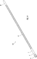
Figure 1 is a side view of one embodiment of the present device; -
Figure 2 is a top rear perspective view of the embodiment shown inFig. 1 ; -
Figure 3 is a partial side view of the embodiment shown inFig. 1 , taken along lines 3-3, illustrating the cutter portion of the surgical cutting tool; -
Figure 4 is a partial front view, taken along lines 4-4 ofFig. 3 , illustrating the construction of the cutting surfaces; -
Figure 5 is a partial section view taken along lines 5-5 ofFig. 4 ; -
Figure 6 is a partial perspective view of an alternative embodiment of the surgical cutting tool; -
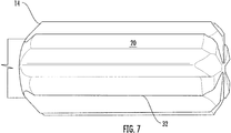
Figure 7 is another perspective view of the embodiment illustrated inFig. 6 ; -
Figure 8 is an alternative embodiment of the surgical cutting tool; -
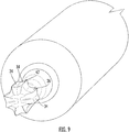
Figure 9 is a perspective end view of the embodiment illustrated inFig. 8 ; -
Figure 10 is a perspective end view of an alternative embodiment of the surgical cutting tool; -
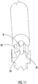
Figure 11 is an end, side perspective view of the embodiment illustrated inFig. 10 ; -
Figure 12 is an end, side perspective view of an alternative embodiment of the surgical cutting tool; -
Figure 13 is a partial perspective view of an alternative embodiment of the present invention, illustrating a fluted shank; -
Figure 14 is a perspective view of the embodiment illustrated inFig. 13 ; -
Figure 15 is a perspective view of an alternative embodiment of the surgical cutting tool; -
Figure 16 is a section view, taken along lines 16-16 ofFig. 15 , illustrating the cross sectional shape of the fluted shank; -
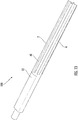
Figure 17 is a perspective view of the embodiment illustrated inFig. 15 , illustrated without the bearings; and -
Figure 18 is a partial perspective view illustrating the surgical cutting tool positioned within a reciprocating grinder. - While the present invention is susceptible of embodiment in various forms, there is shown in the drawings and will hereinafter be described a presently preferred embodiment with the understanding that the present disclosure is to be considered an exemplification of the invention and is not intended to limit the invention to the specific embodiments illustrated.
- Referring generally to
Figs. 1-18 , asurgical cutting tool 100 for cutting bone and tissue is illustrated. The surgical cutting tool includes ashank 2 having a longitudinal axis 4, afirst end 8, and asecond end 10. Theshank 2 has a perimeter surface 6 (Fig. 13 ) extending around the longitudinal axis 4 and being symmetrically shaped to allow at least thesecond end 10 of theperimeter surface 6 to be gripped for rotation about the longitudinal axis 4. Thus, the longitudinal axis 4 is also a rotational axis. In a preferred embodiment, the second end of theshank 10 is round to cooperate with collets, sleeves, drill chucks and the like, as is known in the art. In at least one embodiment, the second end of theshank 10 includes one ormore flats 12. Theflats 12 are constructed and arranged to cooperate with set screws, tangent pins or the like (not shown) to assure that thesurgical cutting tool 100 oscillates the same speed and arc of rotation as the reciprocating grinder 50 (Fig. 18 ) driving thesurgical cutting tool 100. Thefirst end 8 of theshank 2 includes acutter 14, the cutter including anoutside diameter 16; thecutter 14 including two ormore flutes 18, eachflute 18 extending parallel to the longitudinal axis 4 and extending inward from theoutside diameter 16 toward the longitudinal axis 4, forming arecessed flute channel 20; eachflute channel 20 having a pair ofopposing sidewalls face 26 of acutting edge 42 extending along the length of eachflute channel 20 so that eachflute channel 20 provides twoopposing faces 26 providingcutting edges 42, allowing the cutter to cut in both directions when rotationally oscillated around the longitudinal axis 4. To enhance the cutting action and reduce pressure on thecutter 14, eachface 26 includes arake angle 28, said rake angle being divergent with respect to acenter plane 30 extending through said longitudinal/rotational axis 4 when theblade 32 is centered with respect to thecenter plane 30, and wherein therake angle 28 is convergent with respect to saidcenter plane 30 when saidflute 18 is centered with respect to saidcenter plane 30. Each saidblade 32 includes atop rake 34, saidtop rake 34 extending inwardly from saidoutside diameter 16 towards said axis of rotation 4 so that the convergence of theface 26 and thetop rake 34 provides the outermost diameter of saidcutter 14. In at least some embodiments, thetop rake 34 is formed by a radius positioned to provide relief behind theface 26 as thecutter 14 is oscillated. In at least some embodiments, theface 26 andtop rake 34 may includenotches 36 or waves suitable to break theface 26 into shorter segments, thereby reducing load on theface 26 of thecutter 14. Thesenotches 36 may be aligned or, more preferably, offset with respect to each other to eliminate ribs on the cut surface. Thecutter 14 may be formed with an even or an odd number of flutes without departing from the scope of the invention. In general, acutter 14 with a higher number of flutes will remove material faster than a cutter with fewer flutes. Thecutter 14 may be formed of the same material and formed integral with theshank 2. Alternatively, theshank 2 and thecutter 14 may be constructed from different materials, and thecutter 14 may be cemented to theshank 2 with silver solder or the like suitable to secure thecutter 14 to theshank 2. In this manner, materials such as high speed steel and/or carbide may be utilized as desired without departing from the scope of the invention. Coatings known in the art such as, but not limited to, titanium nitride, titanium carbonitride, vanadium carbide and the like, having a higher hardness than the base material may be utilized. Theflutes 18 may extend around the end of the cutter as illustrated inFigs. 1-9 , or alternatively, the end of the cutter may not be constructed to cut as illustrated inFigs. 10-12 . - Referring to
Figs. 13-17 , an alternative embodiment of the present device is illustrated. In this embodiment, theshank 2 is constructed to include shank flutes 40. The shank flutes 40 extend along the length of theshank 2 and extend inwardly from theouter diameter 16 to reduce the rotating weight of thesurgical cutting tool 100. In this manner, thesurgical cutting tool 100 can be oscillated at faster speeds, reducing the inertia of the surgical cutting tool as its direction is changed. The shank flutes 40 may be constructed as flats, channels or any other shape suitable for reducing the rotating mass of the shank without departing from the scope of the invention. - Referring to
Figure 18 , thesurgical cutting tool 100 is illustrated within an oscillating grinder. Such a grinder is described inU.S. Patent Application No. 9,232,953 - It is to be understood that while a certain form of the invention is illustrated, it is not to be limited to the specific form or arrangement of parts herein described and shown. It will be apparent to those skilled in the art that various changes may be made without departing from the scope of the invention, and the invention is not to be considered limited to what is shown and described in the specification.
- One skilled in the art will readily appreciate that the present invention is well adapted to carry out the objects and obtain the ends and advantages mentioned, as well as those inherent therein. Any compounds, methods, procedures and techniques described herein are presently representative of the preferred embodiments, are intended to be exemplary, and are not intended as limitations on the scope. Changes therein and other uses will occur to those skilled in the art which are encompassed within the spirit of the invention and are defined by the scope of the appended claims. Although the invention has been described in connection with specific preferred embodiments, it should be understood that the invention as claimed should not be unduly limited to such specific embodiments. Indeed, various modifications of the described modes for carrying out the invention which are obvious to those skilled in the art are intended to be within the scope of the following claims.
Claims (15)
- A surgical cutting tool comprising:a shank having a longitudinal axis, said shank having a perimeter surface extending around said longitudinal axis, said perimeter surface being symmetrically arranged to allow said perimeter surface to be gripped for rotation about said longitudinal axis, whereby said longitudinal axis is also a rotational axis, said shank also including a first end and a second end;said first end of said shank including a cutter, said cutter including an outside diameter, said cutter including two or more flutes, each said flute extending parallel to said longitudinal axis and extending inward from said outside diameter, forming a recessed flute channel, each said flute channel having a pair of opposing sidewalls, each said sidewall forming a face of a cutting edge extending along the length of each said flute channel, whereby each said flute channel provides two opposing cutting edges to a blade so that said cutting tool cuts in both directions when rotationally oscillated around said rotational axis.
- The surgical cutting tool of Claim 1, wherein each said face includes a rake angle, said rake angle being divergent with respect to a center plane extending through said rotational axis when said blade is centered with respect to said center plane and wherein said rake angle is convergent with respect to said center plane when said flute is centered with respect to said center plane.
- The surgical cutting tool of Claim 1 or 2, wherein each said blade includes a top rake, said top rake extending inwardly from said outside diameter towards said axis of rotation so that the convergence of said face and said top rake provide the outermost diameter of said cutting tool.
- The surgical cutting tool of Claim 1 to 3, wherein said top rake is formed by a radius.
- The surgical cutting tool of Claim 1 to 4, wherein each said face includes notches for breaking said face into shorter segments.
- The surgical cutting tool of Claim 1 to 5, wherein said notches are offset with respect to each other from one said face to another.
- The surgical cutting tool of Claim 1 to 6, wherein a base of each said flute channel is formed as a cylindrical radius.
- The surgical cutting tool of Claim 1 to 7, wherein said cutter includes an even number of said flutes, or wherein said cutter includes an odd number of said flutes.
- The surgical cutting tool of Claim 1 to 8, wherein said cutter is formed integral to said shank.
- The surgical cutting tool of Claim 1 to 9, wherein said cutter is cemented to said first end of said shank.
- The surgical cutting tool of Claim 1 to 10, wherein said cutter is constructed from high speed steel, or wherein said cutter is constructed from carbide.
- The surgical cutting tool of Claim 1 to 11, wherein said cutter includes a surface coating having a higher hardness than the material constructing said cutter.
- The surgical cutting tool of Claim 11 or 12, wherein said surface coating is titanium nitride, or, wherein said surface coating is titanium carbonitride.
- The surgical cutting tool of Claim 1 to 13, wherein said shank includes a plurality of flutes to reduce the weight of said surgical cutting tool.
- The surgical cutting tool of Claim 1 to 14, wherein said flutes are constructed as elongated channels, optionally wherein said channels include a radiused bottom surface.
Applications Claiming Priority (1)
| Application Number | Priority Date | Filing Date | Title |
|---|---|---|---|
| US15/928,885 US10582933B2 (en) | 2018-03-22 | 2018-03-22 | Oscillating surgical cutting tool |
Publications (2)
| Publication Number | Publication Date |
|---|---|
| EP3542741A1 true EP3542741A1 (en) | 2019-09-25 |
| EP3542741B1 EP3542741B1 (en) | 2022-07-20 |
Family
ID=64559432
Family Applications (1)
| Application Number | Title | Priority Date | Filing Date |
|---|---|---|---|
| EP18205734.9A Active EP3542741B1 (en) | 2018-03-22 | 2018-11-12 | Oscillating surgical cutting tool |
Country Status (5)
| Country | Link |
|---|---|
| US (3) | US10582933B2 (en) |
| EP (1) | EP3542741B1 (en) |
| CN (1) | CN110292415B (en) |
| AU (1) | AU2018264064A1 (en) |
| CA (1) | CA3023868A1 (en) |
Families Citing this family (12)
| Publication number | Priority date | Publication date | Assignee | Title |
|---|---|---|---|---|
| USD884172S1 (en) * | 2018-01-12 | 2020-05-12 | Peter L. Bono | Surgical cutting tool |
| USD882792S1 (en) * | 2018-01-31 | 2020-04-28 | Beijing Smtp Technology Co., Ltd. | Ultrasonic cutter head with slotting umbrella |
| US10582933B2 (en) | 2018-03-22 | 2020-03-10 | Capstone Surgical Techologies, LLC | Oscillating surgical cutting tool |
| USD915591S1 (en) * | 2019-01-25 | 2021-04-06 | Beijing Smtp Technology Co., Ltd. | Ultrasonic cutter head for medical purpose |
| CN112155676B (en) * | 2020-09-02 | 2025-09-05 | 深圳核心医疗科技股份有限公司 | Surgical opening device |
| US20240041474A1 (en) * | 2020-12-11 | 2024-02-08 | Stryker European Operations Limited | Surgical Cutting Tool Having A Plurality Of Protuberances And Method Of Manufacturing The Same |
| US12096946B2 (en) * | 2021-01-28 | 2024-09-24 | Globus Medical, Inc. | Vertebral disc cutter and method |
| US20220330994A1 (en) * | 2021-03-30 | 2022-10-20 | Globus Medical, Inc. | Bi-directional drill point screw |
| CN113749728A (en) * | 2021-07-20 | 2021-12-07 | 宋国俊 | Reaming tool for minimally invasive surgery |
| US12582415B2 (en) * | 2022-11-16 | 2026-03-24 | Medtronic Ps Medical, Inc. | Oscillating surgical bone removal tool with fluted cutting head |
| US20250127522A1 (en) * | 2023-10-24 | 2025-04-24 | Medtronic Ps Medical, Inc. | Surgical bur with improved cutting and method of improving cutting effectiveness |
| US12446894B1 (en) | 2025-04-22 | 2025-10-21 | Stryker European Operations Limited | Saw blade for use in performing a medical procedure |
Citations (6)
| Publication number | Priority date | Publication date | Assignee | Title |
|---|---|---|---|---|
| US4197645A (en) * | 1976-07-06 | 1980-04-15 | Scheicher Hans M F | Drill head and bone drill |
| US20060276816A1 (en) * | 2005-06-06 | 2006-12-07 | Concept Matrix, Llc | Multi-Blade Curette Tool |
| WO2009141634A1 (en) * | 2008-05-23 | 2009-11-26 | Osteocare Implant System Limited | A drill bit for use in surgery |
| US20110196398A1 (en) * | 2010-02-11 | 2011-08-11 | Ethicon Endo-Surgery, Inc. | Seal arrangements for ultrasonically powered surgical instruments |
| US9232953B2 (en) | 2012-10-08 | 2016-01-12 | Peter Bono | Cutting tool for bone, cartilage, and disk removal |
| US20170020534A1 (en) * | 2010-06-25 | 2017-01-26 | Depuy Mitek, Llc | Fluted bone awl and method of use |
Family Cites Families (115)
| Publication number | Priority date | Publication date | Assignee | Title |
|---|---|---|---|---|
| US1154159A (en) | 1915-07-12 | 1915-09-21 | Asa Ashworth | Bit for valve-grinders. |
| DE570977C (en) | 1931-10-09 | 1933-02-22 | Wilhelm Ludowici Dr Ing | Dining and serving table |
| US1979905A (en) * | 1932-07-02 | 1934-11-06 | Arderne Scott Thesen Ltd | Process and apparatus for the manufacture of moldings and shaped sections from fiberboards, wood pulp boards, crushed cane boards, beaver boards, and the like |
| US2029114A (en) * | 1934-12-07 | 1936-01-28 | Milne William | Stone saw |
| US2557429A (en) | 1949-10-28 | 1951-06-19 | Zimmer Mfg Company | Surgical bone saw drive |
| US2659398A (en) * | 1951-06-08 | 1953-11-17 | Hervey G Marvin | Kerf planing saw |
| US2795247A (en) * | 1954-07-07 | 1957-06-11 | Skil Corp | Reversible circular saw |
| US2834158A (en) | 1955-01-28 | 1958-05-13 | Gulton Ind Inc | Ultrasonic drill |
| US2831295A (en) | 1955-09-21 | 1958-04-22 | Gulton Ind Inc | Ultrasonic drill |
| US2825186A (en) | 1956-02-27 | 1958-03-04 | Gulton Ind Inc | Ultrasonic drill |
| US2815746A (en) * | 1957-04-10 | 1957-12-10 | Cons Diamond Tool Corp | Cut-off blades for abrasive bodies and their production |
| US3064399A (en) * | 1958-08-04 | 1962-11-20 | Norton Co | Diamond cut-off wheel |
| US3058199A (en) * | 1960-05-26 | 1962-10-16 | Dixie Tool Ind Inc | Cutting tool |
| DE1453332C3 (en) * | 1961-04-05 | 1974-06-06 | Vyzkumny A Vyvojovy Ustav Drevarsky, Prag | Process for the lengthwise cutting of wooden blocks or prisms |
| BE614239A (en) * | 1962-02-22 | 1962-06-18 | Diamant Boart Sa | Cutting disc with diamond segments. |
| US3128755A (en) * | 1962-10-01 | 1964-04-14 | Vanguard Abrasive Corp | Undercut resistant diamond abrasive saw blade |
| GB1170845A (en) | 1967-08-11 | 1969-11-19 | Derouter Brothers Ltd | Improved Portable Power Operated Saw |
| JPS506079B1 (en) * | 1969-06-14 | 1975-03-10 | ||
| US3577579A (en) | 1969-10-29 | 1971-05-04 | John P Duve | Electric toothbrush |
| US3937222A (en) * | 1973-11-09 | 1976-02-10 | Surgical Design Corporation | Surgical instrument employing cutter means |
| DE2427716B1 (en) | 1974-06-08 | 1975-11-13 | Paul Dr Brinckmann | Bone saws for medical purposes |
| US4081704A (en) | 1976-02-13 | 1978-03-28 | Skil Corporation | Powered hand-held tool with unitary sub-assembly mounted by the tool housing sections |
| CH610753A5 (en) | 1976-12-22 | 1979-05-15 | Roland Leuenberger | |
| USD262630S (en) | 1979-01-19 | 1982-01-12 | Robert W. Lee | Drill bit |
| JPS5826771B2 (en) | 1979-07-03 | 1983-06-04 | ユリイ イグナテイエビツチ ドドノフ | Magnetron type microwave device |
| JPS5613462A (en) | 1979-07-10 | 1981-02-09 | Sumitomo Metal Ind Ltd | Line pipe steel with superior hydrogen sulfide crack resistance |
| US4267814A (en) * | 1979-12-06 | 1981-05-19 | Federal-Mogul Corporation | Abrasive saw blade for trapezoidal grooving |
| DE3016660C2 (en) * | 1980-04-30 | 1982-11-18 | Günther 3155 Edemissen Graßmann | Saw blade |
| JPS5826771U (en) | 1981-08-10 | 1983-02-21 | ソニー株式会社 | Cassette ejection mechanism in recording/playback equipment |
| US4596243A (en) | 1983-05-25 | 1986-06-24 | Bray Robert S | Surgical methods and apparatus for bone removal |
| US4550708A (en) * | 1983-07-06 | 1985-11-05 | Federal-Mogul Corporation | Abrasive cutting wheel for cutting rock-like material |
| DE3466474D1 (en) | 1984-01-12 | 1987-11-05 | Karl Storz | Operating instrument with an ultrasonic drill probe |
| US4556347A (en) | 1984-05-11 | 1985-12-03 | Lockheed Corporation | Split-point twist drill |
| US4706659A (en) * | 1984-12-05 | 1987-11-17 | Regents Of The University Of Michigan | Flexible connecting shaft for intramedullary reamer |
| US4739745A (en) * | 1985-05-21 | 1988-04-26 | N E D Corp. | Circular diamond saw blade incorporating a novel cutting segment |
| US4705017A (en) * | 1985-08-19 | 1987-11-10 | Federal-Mogul Corporation | Stress resistant abrasive cutting wheel |
| US4932935A (en) | 1986-09-15 | 1990-06-12 | Barry Swartz | Assisted lipectomy device |
| EP0261260A1 (en) | 1986-09-23 | 1988-03-30 | Heinz-Jürgen List | Surgical bone drill |
| US4854295A (en) * | 1988-06-01 | 1989-08-08 | Federal-Mogul Corporation | Wear resistant abrasive cutting wheel |
| JPH02298421A (en) * | 1989-05-09 | 1990-12-10 | Kaken:Kk | Structure of tooth part of rotational saw and manufacture thereof |
| DE3937850A1 (en) | 1989-11-14 | 1991-05-16 | Braun Ag | ELECTRIC TOOTHBRUSH WITH ROTATING BRUSH HOLDER |
| US5184597A (en) * | 1990-04-27 | 1993-02-09 | Edward Chiuminatta | Apparatus and method for cutting unhardened concrete |
| US5092875A (en) | 1990-04-30 | 1992-03-03 | Mclees Donald J | Bone saw for tendon transplant surgery |
| US5522829A (en) | 1992-04-16 | 1996-06-04 | Arthur D. Little Enterprises, Inc. | Surgical cutting instrument |
| WO1993025151A1 (en) | 1992-06-12 | 1993-12-23 | Larry Steven Nichter | Wire driver and method |
| US5269355A (en) * | 1992-09-08 | 1993-12-14 | Bowen Randal G | Cutting wheel for stump-grinding apparatus |
| SE508466C2 (en) | 1993-09-14 | 1998-10-12 | Seco Tools Ab | Drill |
| US5626444A (en) * | 1994-03-09 | 1997-05-06 | Campian; Jonathon | Rotary cutting tool |
| US5728118A (en) | 1995-03-29 | 1998-03-17 | Linvatec Corporation | Apparatus and method for harvesting a bone-tendon-bone ligament graft |
| DE19523016C5 (en) | 1995-06-24 | 2005-04-07 | Braun Gmbh | Brush part for an electric toothbrush |
| US6015420A (en) * | 1997-03-06 | 2000-01-18 | Scimed Life Systems, Inc. | Atherectomy device for reducing damage to vessels and/or in-vivo stents |
| US7540875B2 (en) | 1998-06-01 | 2009-06-02 | Avatar Design & Development, Inc. | Surgical cutting tool with automatically retractable blade assembly |
| US6083228A (en) | 1998-06-09 | 2000-07-04 | Michelson; Gary K. | Device and method for preparing a space between adjacent vertebrae to receive an insert |
| EP1681021A3 (en) | 1998-06-09 | 2009-04-15 | Warsaw Orthopedic, Inc. | Abrading element for preparing a space between adjacent vertebral bodies |
| US6321738B1 (en) * | 1998-08-28 | 2001-11-27 | Diamond Products Joint Venture | Diamond saw blade |
| US6267542B1 (en) | 1999-01-15 | 2001-07-31 | Avraham Salmon | Drill bit having a chiseless bit tip |
| DE29901723U1 (en) | 1999-02-02 | 2000-06-29 | Synthes AG Chur, Chur, Graubünden | Device for extracting bone chips |
| US6790215B2 (en) * | 1999-04-30 | 2004-09-14 | Edwards Lifesciences Corporation | Method of use for percutaneous material removal device and tip |
| US6238405B1 (en) * | 1999-04-30 | 2001-05-29 | Edwards Lifesciences Corp. | Percutaneous material removal device and method |
| US6234725B1 (en) * | 1999-12-14 | 2001-05-22 | Jonathan R. Campian | Rotary cutting tool |
| US20040050603A1 (en) | 2000-02-23 | 2004-03-18 | Jaeger Eduard A. | Mounting arrangement for vehicle power source |
| US6422229B1 (en) * | 2000-06-29 | 2002-07-23 | Advanced Micro Devices, Inc. | Saw blade for cutting integrated circuit package boards |
| CN2436108Y (en) | 2000-08-25 | 2001-06-27 | 高南翔 | Front extended sternum saw |
| US7387612B2 (en) | 2001-03-28 | 2008-06-17 | Cybersonics, Inc. | Floating probe for ultrasonic transducers |
| US20020194975A1 (en) * | 2001-06-08 | 2002-12-26 | Bishop Ralph Carl | Saw blades with tiers of teeth |
| US6498421B1 (en) | 2001-06-15 | 2002-12-24 | Amega Lab, L.L.C. | Ultrasonic drilling device with arc-shaped probe |
| US6721986B2 (en) | 2001-06-28 | 2004-04-20 | Qingping Zhuan | Electric toothbrush |
| US20030204199A1 (en) | 2002-04-30 | 2003-10-30 | Novak Theodore A. D. | Device and method for ultrasonic tissue excision with tissue selectivity |
| DE10243104A1 (en) | 2002-09-17 | 2004-03-25 | Gebr. Brasseler Gmbh & Co. Kg | Rotating ceramic tool with a ceramic cutting head bonded to a ceramic or metal support shaft |
| US20040147934A1 (en) | 2002-10-18 | 2004-07-29 | Kiester P. Douglas | Oscillating, steerable, surgical burring tool and method of using the same |
| DE50304528D1 (en) | 2003-01-09 | 2006-09-14 | Synthes Ag | DEVICE FOR CONVERTING A ROTATING MOVEMENT INTO AN OSCILLATING MOVEMENT |
| US6899685B2 (en) | 2003-01-24 | 2005-05-31 | Acueity, Inc. | Biopsy device |
| US6878051B2 (en) * | 2003-02-05 | 2005-04-12 | Saint-Gobain Abrasives Technology Company | Saw blade with shaped gullets |
| CN2629654Y (en) | 2003-06-19 | 2004-08-04 | 北京茵普兰人工关节有限公司 | Portable cutting tool for operation |
| US7090442B2 (en) | 2003-12-09 | 2006-08-15 | The Boeing Company | Shaper router and method |
| US7842044B2 (en) | 2003-12-17 | 2010-11-30 | Depuy Spine, Inc. | Instruments and methods for bone anchor engagement and spinal rod reduction |
| EP1694226B1 (en) | 2003-12-17 | 2009-09-02 | DePuy Spine, Inc. | Instruments and methods for bone anchor engagement and spinal rod reduction |
| US8025662B2 (en) | 2004-03-25 | 2011-09-27 | Symmetry Medical, Inc. | Bidirectional reaming cutter |
| US20060130622A1 (en) * | 2004-12-22 | 2006-06-22 | 3M Innovative Properties Company | Circular blade and methods for using same |
| JP4456499B2 (en) | 2005-02-10 | 2010-04-28 | 株式会社マキタ | Work tools |
| US20060229624A1 (en) | 2005-03-31 | 2006-10-12 | Zimmer Technology, Inc. | Orthopaedic cutting instrument and method |
| US8142460B2 (en) | 2005-04-15 | 2012-03-27 | Integra Lifesciences (Ireland) Ltd. | Bone abrading ultrasonic horns |
| US8092475B2 (en) | 2005-04-15 | 2012-01-10 | Integra Lifesciences (Ireland) Ltd. | Ultrasonic horn for removal of hard tissue |
| WO2007008703A2 (en) | 2005-07-08 | 2007-01-18 | Conceptual Gray, Llc | Apparatus and method thereof for drilling holes in discrete controlled increments |
| KR20070019513A (en) | 2005-10-26 | 2007-02-15 | 김용철 | Easy to assemble metal balls |
| GB2430396A (en) | 2005-09-23 | 2007-03-28 | Thomas Hoogland | A surgical drill |
| US8465491B2 (en) | 2006-06-01 | 2013-06-18 | Osteo Innovations Llc | Bone drill |
| US8480673B2 (en) | 2006-06-01 | 2013-07-09 | Osteo Innovations Llc | Cavity creation device and methods of use |
| DE202006009337U1 (en) | 2006-06-14 | 2006-08-17 | Brugg Rohr Ag, Holding | Heat-insulated pipe used in a heating system and in drinking water and effluent lines comprises an inner pipe, a heat insulating layer surrounding the inner pipe, a film surrounding the heat insulating layer and a corrugated outer pipe |
| US8007506B2 (en) * | 2006-06-30 | 2011-08-30 | Atheromed, Inc. | Atherectomy devices and methods |
| US20080108010A1 (en) | 2006-11-07 | 2008-05-08 | Wen-Hao Wang | Illuminator for a dental drill |
| US8684253B2 (en) | 2007-01-10 | 2014-04-01 | Ethicon Endo-Surgery, Inc. | Surgical instrument with wireless communication between a control unit of a robotic system and remote sensor |
| US8828001B2 (en) | 2007-02-20 | 2014-09-09 | Gabriel Institute, Inc. | Bone drill and methods of treatment |
| MX2009010707A (en) | 2007-04-04 | 2010-03-26 | Alexandria Res Technologies Llc | Apparatus and method for sculpting the surface of a joint. |
| US8353912B2 (en) | 2007-06-01 | 2013-01-15 | Misonix, Incorporated | Ultrasonic spinal surgery method |
| US20090024129A1 (en) | 2007-07-19 | 2009-01-22 | Jeremy Gordon | Perforator with inner and outer drills and a drive head, the inner drill configured to move against the outer drill in order to disengage from the drive head |
| WO2009151926A2 (en) | 2008-05-23 | 2009-12-17 | Spine View, Inc. | Method and devices for treating spinal stenosis |
| US20110015635A1 (en) | 2009-07-17 | 2011-01-20 | Aryan Henry E | Apparatus and method for facilitating intervertebral arthrodesis and disc space preparation as part of treatment of spinal degenerative disease |
| US20110184447A1 (en) | 2010-01-26 | 2011-07-28 | Warsaw Orthopedic, Inc. | Surgical cutting tool and method |
| US8961547B2 (en) | 2010-02-11 | 2015-02-24 | Ethicon Endo-Surgery, Inc. | Ultrasonic surgical instruments with moving cutting implement |
| TWI494076B (en) | 2011-04-18 | 2015-08-01 | Univ Nat Central | Medical drill |
| CN106037977B (en) | 2011-05-02 | 2018-06-29 | 沃特皮克公司 | The method for designing acoustic toothbrush |
| JP5806407B2 (en) * | 2011-09-01 | 2015-11-10 | コヴィディエン リミテッド パートナーシップ | Catheter with helical drive shaft and manufacturing method |
| US9186156B2 (en) | 2012-03-14 | 2015-11-17 | Stryker Corporation | Surgical drill with drive shaft and drill bit that, after disengaging the drill bit from the drive shaft, allows the drill bit to be driven in reverse |
| US9232952B2 (en) * | 2012-04-16 | 2016-01-12 | Medtronic Ps Medical, Inc. | Surgical bur with non-paired flutes |
| US20140150620A1 (en) * | 2012-11-30 | 2014-06-05 | Irwin Industrial Tool Company | Saw Blade Having Different Material Teeth and Method of Manufacture |
| US10076349B2 (en) | 2013-03-15 | 2018-09-18 | Misonix, Inc. | Ultrasonic surgical drill and associated surgical method |
| WO2015006296A1 (en) | 2013-07-09 | 2015-01-15 | Stryker Corporation | Surgical drill having brake that, upon the drill bit penetrating through bone, prevents further insertion of the drill bit |
| EP3590445B1 (en) | 2013-08-21 | 2022-11-16 | Michael J. Scianamblo | Precessional-motion drilling tool |
| DE102013112632A1 (en) * | 2013-11-15 | 2015-05-21 | C. & E. Fein Gmbh | Saw blade for an oscillating driven saw |
| USD779670S1 (en) | 2015-06-15 | 2017-02-21 | Echo Therapeutics, Inc. | Abrasion device with abrasive tip |
| USD800903S1 (en) | 2016-02-09 | 2017-10-24 | Medtronic Ps Medical, Inc. | Surgical tool |
| US10335170B2 (en) * | 2016-02-12 | 2019-07-02 | Viant As&O Holdings, Llc | Cutting heads for intramedullary reamers |
| EP3496630B1 (en) * | 2016-08-14 | 2024-01-17 | Greatbatch Ltd. | Cutting head for an intramedullary reamer |
| US10582933B2 (en) | 2018-03-22 | 2020-03-10 | Capstone Surgical Techologies, LLC | Oscillating surgical cutting tool |
-
2018
- 2018-03-22 US US15/928,885 patent/US10582933B2/en active Active
- 2018-11-12 AU AU2018264064A patent/AU2018264064A1/en not_active Abandoned
- 2018-11-12 CN CN201811340348.XA patent/CN110292415B/en active Active
- 2018-11-12 EP EP18205734.9A patent/EP3542741B1/en active Active
- 2018-11-13 CA CA3023868A patent/CA3023868A1/en active Pending
-
2020
- 2020-01-27 US US16/773,564 patent/US11766266B2/en active Active
-
2023
- 2023-08-23 US US18/454,135 patent/US12605166B2/en active Active
Patent Citations (6)
| Publication number | Priority date | Publication date | Assignee | Title |
|---|---|---|---|---|
| US4197645A (en) * | 1976-07-06 | 1980-04-15 | Scheicher Hans M F | Drill head and bone drill |
| US20060276816A1 (en) * | 2005-06-06 | 2006-12-07 | Concept Matrix, Llc | Multi-Blade Curette Tool |
| WO2009141634A1 (en) * | 2008-05-23 | 2009-11-26 | Osteocare Implant System Limited | A drill bit for use in surgery |
| US20110196398A1 (en) * | 2010-02-11 | 2011-08-11 | Ethicon Endo-Surgery, Inc. | Seal arrangements for ultrasonically powered surgical instruments |
| US20170020534A1 (en) * | 2010-06-25 | 2017-01-26 | Depuy Mitek, Llc | Fluted bone awl and method of use |
| US9232953B2 (en) | 2012-10-08 | 2016-01-12 | Peter Bono | Cutting tool for bone, cartilage, and disk removal |
Also Published As
| Publication number | Publication date |
|---|---|
| EP3542741B1 (en) | 2022-07-20 |
| US11766266B2 (en) | 2023-09-26 |
| CN110292415B (en) | 2024-08-06 |
| US12605166B2 (en) | 2026-04-21 |
| US20190290290A1 (en) | 2019-09-26 |
| US10582933B2 (en) | 2020-03-10 |
| US20240041473A1 (en) | 2024-02-08 |
| CA3023868A1 (en) | 2019-09-22 |
| CN110292415A (en) | 2019-10-01 |
| US20200155167A1 (en) | 2020-05-21 |
| AU2018264064A1 (en) | 2019-10-10 |
Similar Documents
| Publication | Publication Date | Title |
|---|---|---|
| US12605166B2 (en) | Oscillating surgical cutting tool | |
| CA2578787C (en) | Helical flute end mill with multi-section cutting edge | |
| CA2494062C (en) | A drill bit and method for producing a drill bit | |
| CN103025461B (en) | end mill | |
| US20060212060A1 (en) | Arthroscopic shaver and method of manufacturing same | |
| US8709012B2 (en) | Surgical cutting tool | |
| JPH1170127A (en) | Stagger cut teeth | |
| JP4620199B2 (en) | Drill with handle with spiral groove to transport chips | |
| JP6359419B2 (en) | drill | |
| JP2005034911A (en) | Tool for countersinking, deburring, and/or spindling hole | |
| JP6729853B2 (en) | Drill | |
| US6796751B2 (en) | Serrated ball nose end mill insert | |
| HK40014853A (en) | Oscillating surgical cutting tool | |
| HK40014853B (en) | Oscillating surgical cutting tool | |
| JP4370966B2 (en) | Grooved tool | |
| JP2003275913A (en) | Drill | |
| JP2009233851A (en) | Grooved tool | |
| JP4610102B2 (en) | Ball end mill | |
| JP3754270B2 (en) | Taper blade end mill | |
| JPS5841060Y2 (en) | Throwaway tip | |
| JP3188415B2 (en) | Reamer and hole finishing method using the same | |
| JP4055141B2 (en) | Drills, throwaway drills and throwaway tips | |
| JP2004314258A (en) | Throw-away type drilling tool | |
| JP6447566B2 (en) | Drilling tool | |
| JPH0819911A (en) | Drill |
Legal Events
| Date | Code | Title | Description |
|---|---|---|---|
| PUAI | Public reference made under article 153(3) epc to a published international application that has entered the european phase |
Free format text: ORIGINAL CODE: 0009012 |
|
| STAA | Information on the status of an ep patent application or granted ep patent |
Free format text: STATUS: THE APPLICATION HAS BEEN PUBLISHED |
|
| AK | Designated contracting states |
Kind code of ref document: A1 Designated state(s): AL AT BE BG CH CY CZ DE DK EE ES FI FR GB GR HR HU IE IS IT LI LT LU LV MC MK MT NL NO PL PT RO RS SE SI SK SM TR |
|
| AX | Request for extension of the european patent |
Extension state: BA ME |
|
| STAA | Information on the status of an ep patent application or granted ep patent |
Free format text: STATUS: REQUEST FOR EXAMINATION WAS MADE |
|
| 17P | Request for examination filed |
Effective date: 20200227 |
|
| RBV | Designated contracting states (corrected) |
Designated state(s): AL AT BE BG CH CY CZ DE DK EE ES FI FR GB GR HR HU IE IS IT LI LT LU LV MC MK MT NL NO PL PT RO RS SE SI SK SM TR |
|
| REG | Reference to a national code |
Ref country code: HK Ref legal event code: DE Ref document number: 40014853 Country of ref document: HK |
|
| RAP1 | Party data changed (applicant data changed or rights of an application transferred) |
Owner name: GLOBUS MEDICAL, INC. |
|
| GRAP | Despatch of communication of intention to grant a patent |
Free format text: ORIGINAL CODE: EPIDOSNIGR1 |
|
| STAA | Information on the status of an ep patent application or granted ep patent |
Free format text: STATUS: GRANT OF PATENT IS INTENDED |
|
| RIC1 | Information provided on ipc code assigned before grant |
Ipc: A61B 17/16 20060101ALI20220414BHEP Ipc: A61B 17/32 20060101AFI20220414BHEP |
|
| INTG | Intention to grant announced |
Effective date: 20220510 |
|
| GRAS | Grant fee paid |
Free format text: ORIGINAL CODE: EPIDOSNIGR3 |
|
| GRAA | (expected) grant |
Free format text: ORIGINAL CODE: 0009210 |
|
| STAA | Information on the status of an ep patent application or granted ep patent |
Free format text: STATUS: THE PATENT HAS BEEN GRANTED |
|
| AK | Designated contracting states |
Kind code of ref document: B1 Designated state(s): AL AT BE BG CH CY CZ DE DK EE ES FI FR GB GR HR HU IE IS IT LI LT LU LV MC MK MT NL NO PL PT RO RS SE SI SK SM TR |
|
| REG | Reference to a national code |
Ref country code: CH Ref legal event code: EP |
|
| REG | Reference to a national code |
Ref country code: DE Ref legal event code: R096 Ref document number: 602018038075 Country of ref document: DE |
|
| REG | Reference to a national code |
Ref country code: AT Ref legal event code: REF Ref document number: 1505048 Country of ref document: AT Kind code of ref document: T Effective date: 20220815 |
|
| REG | Reference to a national code |
Ref country code: IE Ref legal event code: FG4D |
|
| REG | Reference to a national code |
Ref country code: LT Ref legal event code: MG9D |
|
| REG | Reference to a national code |
Ref country code: NL Ref legal event code: MP Effective date: 20220720 |
|
| PG25 | Lapsed in a contracting state [announced via postgrant information from national office to epo] |
Ref country code: SE Free format text: LAPSE BECAUSE OF FAILURE TO SUBMIT A TRANSLATION OF THE DESCRIPTION OR TO PAY THE FEE WITHIN THE PRESCRIBED TIME-LIMIT Effective date: 20220720 Ref country code: RS Free format text: LAPSE BECAUSE OF FAILURE TO SUBMIT A TRANSLATION OF THE DESCRIPTION OR TO PAY THE FEE WITHIN THE PRESCRIBED TIME-LIMIT Effective date: 20220720 Ref country code: PT Free format text: LAPSE BECAUSE OF FAILURE TO SUBMIT A TRANSLATION OF THE DESCRIPTION OR TO PAY THE FEE WITHIN THE PRESCRIBED TIME-LIMIT Effective date: 20221121 Ref country code: NO Free format text: LAPSE BECAUSE OF FAILURE TO SUBMIT A TRANSLATION OF THE DESCRIPTION OR TO PAY THE FEE WITHIN THE PRESCRIBED TIME-LIMIT Effective date: 20221020 Ref country code: NL Free format text: LAPSE BECAUSE OF FAILURE TO SUBMIT A TRANSLATION OF THE DESCRIPTION OR TO PAY THE FEE WITHIN THE PRESCRIBED TIME-LIMIT Effective date: 20220720 Ref country code: LV Free format text: LAPSE BECAUSE OF FAILURE TO SUBMIT A TRANSLATION OF THE DESCRIPTION OR TO PAY THE FEE WITHIN THE PRESCRIBED TIME-LIMIT Effective date: 20220720 Ref country code: LT Free format text: LAPSE BECAUSE OF FAILURE TO SUBMIT A TRANSLATION OF THE DESCRIPTION OR TO PAY THE FEE WITHIN THE PRESCRIBED TIME-LIMIT Effective date: 20220720 Ref country code: FI Free format text: LAPSE BECAUSE OF FAILURE TO SUBMIT A TRANSLATION OF THE DESCRIPTION OR TO PAY THE FEE WITHIN THE PRESCRIBED TIME-LIMIT Effective date: 20220720 Ref country code: ES Free format text: LAPSE BECAUSE OF FAILURE TO SUBMIT A TRANSLATION OF THE DESCRIPTION OR TO PAY THE FEE WITHIN THE PRESCRIBED TIME-LIMIT Effective date: 20220720 |
|
| REG | Reference to a national code |
Ref country code: AT Ref legal event code: MK05 Ref document number: 1505048 Country of ref document: AT Kind code of ref document: T Effective date: 20220720 |
|
| PG25 | Lapsed in a contracting state [announced via postgrant information from national office to epo] |
Ref country code: PL Free format text: LAPSE BECAUSE OF FAILURE TO SUBMIT A TRANSLATION OF THE DESCRIPTION OR TO PAY THE FEE WITHIN THE PRESCRIBED TIME-LIMIT Effective date: 20220720 Ref country code: IS Free format text: LAPSE BECAUSE OF FAILURE TO SUBMIT A TRANSLATION OF THE DESCRIPTION OR TO PAY THE FEE WITHIN THE PRESCRIBED TIME-LIMIT Effective date: 20221120 Ref country code: HR Free format text: LAPSE BECAUSE OF FAILURE TO SUBMIT A TRANSLATION OF THE DESCRIPTION OR TO PAY THE FEE WITHIN THE PRESCRIBED TIME-LIMIT Effective date: 20220720 Ref country code: GR Free format text: LAPSE BECAUSE OF FAILURE TO SUBMIT A TRANSLATION OF THE DESCRIPTION OR TO PAY THE FEE WITHIN THE PRESCRIBED TIME-LIMIT Effective date: 20221021 |
|
| REG | Reference to a national code |
Ref country code: DE Ref legal event code: R097 Ref document number: 602018038075 Country of ref document: DE |
|
| PG25 | Lapsed in a contracting state [announced via postgrant information from national office to epo] |
Ref country code: SM Free format text: LAPSE BECAUSE OF FAILURE TO SUBMIT A TRANSLATION OF THE DESCRIPTION OR TO PAY THE FEE WITHIN THE PRESCRIBED TIME-LIMIT Effective date: 20220720 Ref country code: RO Free format text: LAPSE BECAUSE OF FAILURE TO SUBMIT A TRANSLATION OF THE DESCRIPTION OR TO PAY THE FEE WITHIN THE PRESCRIBED TIME-LIMIT Effective date: 20220720 Ref country code: DK Free format text: LAPSE BECAUSE OF FAILURE TO SUBMIT A TRANSLATION OF THE DESCRIPTION OR TO PAY THE FEE WITHIN THE PRESCRIBED TIME-LIMIT Effective date: 20220720 Ref country code: CZ Free format text: LAPSE BECAUSE OF FAILURE TO SUBMIT A TRANSLATION OF THE DESCRIPTION OR TO PAY THE FEE WITHIN THE PRESCRIBED TIME-LIMIT Effective date: 20220720 Ref country code: AT Free format text: LAPSE BECAUSE OF FAILURE TO SUBMIT A TRANSLATION OF THE DESCRIPTION OR TO PAY THE FEE WITHIN THE PRESCRIBED TIME-LIMIT Effective date: 20220720 |
|
| PLBE | No opposition filed within time limit |
Free format text: ORIGINAL CODE: 0009261 |
|
| STAA | Information on the status of an ep patent application or granted ep patent |
Free format text: STATUS: NO OPPOSITION FILED WITHIN TIME LIMIT |
|
| PG25 | Lapsed in a contracting state [announced via postgrant information from national office to epo] |
Ref country code: SK Free format text: LAPSE BECAUSE OF FAILURE TO SUBMIT A TRANSLATION OF THE DESCRIPTION OR TO PAY THE FEE WITHIN THE PRESCRIBED TIME-LIMIT Effective date: 20220720 Ref country code: EE Free format text: LAPSE BECAUSE OF FAILURE TO SUBMIT A TRANSLATION OF THE DESCRIPTION OR TO PAY THE FEE WITHIN THE PRESCRIBED TIME-LIMIT Effective date: 20220720 |
|
| 26N | No opposition filed |
Effective date: 20230421 |
|
| PG25 | Lapsed in a contracting state [announced via postgrant information from national office to epo] |
Ref country code: MC Free format text: LAPSE BECAUSE OF FAILURE TO SUBMIT A TRANSLATION OF THE DESCRIPTION OR TO PAY THE FEE WITHIN THE PRESCRIBED TIME-LIMIT Effective date: 20220720 Ref country code: AL Free format text: LAPSE BECAUSE OF FAILURE TO SUBMIT A TRANSLATION OF THE DESCRIPTION OR TO PAY THE FEE WITHIN THE PRESCRIBED TIME-LIMIT Effective date: 20220720 |
|
| REG | Reference to a national code |
Ref country code: CH Ref legal event code: PL |
|
| REG | Reference to a national code |
Ref country code: BE Ref legal event code: MM Effective date: 20221130 |
|
| PG25 | Lapsed in a contracting state [announced via postgrant information from national office to epo] |
Ref country code: LI Free format text: LAPSE BECAUSE OF NON-PAYMENT OF DUE FEES Effective date: 20221130 Ref country code: CH Free format text: LAPSE BECAUSE OF NON-PAYMENT OF DUE FEES Effective date: 20221130 |
|
| PG25 | Lapsed in a contracting state [announced via postgrant information from national office to epo] |
Ref country code: SI Free format text: LAPSE BECAUSE OF FAILURE TO SUBMIT A TRANSLATION OF THE DESCRIPTION OR TO PAY THE FEE WITHIN THE PRESCRIBED TIME-LIMIT Effective date: 20220720 Ref country code: LU Free format text: LAPSE BECAUSE OF NON-PAYMENT OF DUE FEES Effective date: 20221112 |
|
| PG25 | Lapsed in a contracting state [announced via postgrant information from national office to epo] |
Ref country code: IE Free format text: LAPSE BECAUSE OF NON-PAYMENT OF DUE FEES Effective date: 20221112 |
|
| PG25 | Lapsed in a contracting state [announced via postgrant information from national office to epo] |
Ref country code: FR Free format text: LAPSE BECAUSE OF NON-PAYMENT OF DUE FEES Effective date: 20221130 Ref country code: BE Free format text: LAPSE BECAUSE OF NON-PAYMENT OF DUE FEES Effective date: 20221130 |
|
| PG25 | Lapsed in a contracting state [announced via postgrant information from national office to epo] |
Ref country code: HU Free format text: LAPSE BECAUSE OF FAILURE TO SUBMIT A TRANSLATION OF THE DESCRIPTION OR TO PAY THE FEE WITHIN THE PRESCRIBED TIME-LIMIT; INVALID AB INITIO Effective date: 20181112 |
|
| PG25 | Lapsed in a contracting state [announced via postgrant information from national office to epo] |
Ref country code: CY Free format text: LAPSE BECAUSE OF FAILURE TO SUBMIT A TRANSLATION OF THE DESCRIPTION OR TO PAY THE FEE WITHIN THE PRESCRIBED TIME-LIMIT Effective date: 20220720 |
|
| PG25 | Lapsed in a contracting state [announced via postgrant information from national office to epo] |
Ref country code: MK Free format text: LAPSE BECAUSE OF FAILURE TO SUBMIT A TRANSLATION OF THE DESCRIPTION OR TO PAY THE FEE WITHIN THE PRESCRIBED TIME-LIMIT Effective date: 20220720 Ref country code: IT Free format text: LAPSE BECAUSE OF FAILURE TO SUBMIT A TRANSLATION OF THE DESCRIPTION OR TO PAY THE FEE WITHIN THE PRESCRIBED TIME-LIMIT Effective date: 20220720 |
|
| PG25 | Lapsed in a contracting state [announced via postgrant information from national office to epo] |
Ref country code: BG Free format text: LAPSE BECAUSE OF FAILURE TO SUBMIT A TRANSLATION OF THE DESCRIPTION OR TO PAY THE FEE WITHIN THE PRESCRIBED TIME-LIMIT Effective date: 20220720 |
|
| PG25 | Lapsed in a contracting state [announced via postgrant information from national office to epo] |
Ref country code: MT Free format text: LAPSE BECAUSE OF FAILURE TO SUBMIT A TRANSLATION OF THE DESCRIPTION OR TO PAY THE FEE WITHIN THE PRESCRIBED TIME-LIMIT Effective date: 20220720 |
|
| PGFP | Annual fee paid to national office [announced via postgrant information from national office to epo] |
Ref country code: GB Payment date: 20250918 Year of fee payment: 8 |
|
| PG25 | Lapsed in a contracting state [announced via postgrant information from national office to epo] |
Ref country code: TR Free format text: LAPSE BECAUSE OF FAILURE TO SUBMIT A TRANSLATION OF THE DESCRIPTION OR TO PAY THE FEE WITHIN THE PRESCRIBED TIME-LIMIT Effective date: 20220720 |
|
| PGFP | Annual fee paid to national office [announced via postgrant information from national office to epo] |
Ref country code: DE Payment date: 20250916 Year of fee payment: 8 |