JP4610102B2 - Ball end mill - Google Patents
Ball end mill Download PDFInfo
- Publication number
- JP4610102B2 JP4610102B2 JP2001047571A JP2001047571A JP4610102B2 JP 4610102 B2 JP4610102 B2 JP 4610102B2 JP 2001047571 A JP2001047571 A JP 2001047571A JP 2001047571 A JP2001047571 A JP 2001047571A JP 4610102 B2 JP4610102 B2 JP 4610102B2
- Authority
- JP
- Japan
- Prior art keywords
- concave portion
- ball
- chisel
- tool
- end mill
- Prior art date
- Legal status (The legal status is an assumption and is not a legal conclusion. Google has not performed a legal analysis and makes no representation as to the accuracy of the status listed.)
- Expired - Fee Related
Links
Images


Classifications
-
- B—PERFORMING OPERATIONS; TRANSPORTING
- B23—MACHINE TOOLS; METAL-WORKING NOT OTHERWISE PROVIDED FOR
- B23C—MILLING
- B23C5/00—Milling-cutters
- B23C5/02—Milling-cutters characterised by the shape of the cutter
- B23C5/10—Shank-type cutters, i.e. with an integral shaft
- B23C5/1009—Ball nose end mills
-
- B—PERFORMING OPERATIONS; TRANSPORTING
- B23—MACHINE TOOLS; METAL-WORKING NOT OTHERWISE PROVIDED FOR
- B23C—MILLING
- B23C2210/00—Details of milling cutters
- B23C2210/54—Configuration of the cutting part
Landscapes
- Engineering & Computer Science (AREA)
- Mechanical Engineering (AREA)
- Milling Processes (AREA)
Description
【0001】
【産業上の利用分野】
本願発明は、マシニングセンタ等の工作機械を使用して用いる仕上げ加工用のボールエンドミルの改良に関し、更に詳しくは、ボ−ルエンドミルのボ−ル中心部の形状に関する。
【0002】
【従来の技術】
ボールエンドミルの場合、ボール中心部付近は、工具回転軸近傍となり、切削速度が十分に得られず、特に平面に近い底面の切削では、ボール刃の逃げ面同士で形成されたチゼルエッジを有する部位(以下、チゼル部と称する。)において、該チゼルエッジにより生成された切り屑の逃げ場がなく、該切り屑はチゼル部と加工面の間で押し潰され、加工面に凝着したり、チゼルエッジに溶着し、構成刃先を形成することにより削り過ぎや、溶着、脱落を繰り返すことにより脱落時に工具の母材ごと欠落し、切れ味劣化によるムシレ加工面を形成する等、平面に近い底面の加工面粗さが得られない状態であった。
【0003】
そこで、平面に近い底面の加工面粗さを良好にする目的で改善されたものとして、特開2000−233311号公報に開示される仕上げ用ボールエンドミルがあり、ボールエンドミルのボール中心部分の強度を高め、かつ切り屑排出性を向上することによってチッピングを防止し、工具寿命を延長するとともに仕上げ面粗さを向上するというものである。
【0004】
【発明が解決しようとする課題】
通常、ボール刃で切削された切り屑は、該ボール刃のアール部ギャッシュを介して排出されるが、工具正面視でボール刃を形成させる互いのアール部ギャッシュの間隔(以下、チゼル幅と称する。)を直径とする円(以下、チゼル内接円と称する。)の内側は、該アール部ギャッシュと交わりがなく、切り屑の逃げ場がなく、切り屑排出性を考慮するにおいて、チゼル幅の設定が重要となる。
【0005】
しかしながら、前述の通りチゼル幅を大きくするとチゼル内接円も大きくなり、切り屑の排出性において課題があり、小さくするとチゼル部の強度が弱く、特に、マルテンサイト系ステンレス鋼に代表される硬さHRC45を超えるような硬くて溶着及び凝着し易い被削材では、その硬さとともに、切削加工中に切れ刃に溶着、脱落を繰り返すこととなり、脱落時に工具の母材ごと欠落し、工具寿命や加工面粗さに課題があった。
【0006】
また、特開2000−233311号公報に開示されている仕上げ用ボールエンドミルでは、2枚のボール刃1のすくい面を含む平面の間隔が該ボール刃の半径の3%以下、即ちボール刃直径の1.5%以下に設定してあるが、重要点であるチゼル幅5の記載が無く、ボール中心付近の切り屑排出性の面から、その効果は極めて少ないものと考えられる。
【0007】
ボール刃や外周刃のように、切れ刃設計に自由度があり、切れ刃強度を持たしながら十分なチップポケットが確保できる部位は問題ないが、大きな負のすくい角を有し、且つ切れ刃設計上自由度が少ないチゼルエッジが切れ刃となるボール中心部の形状において課題があった。
【0008】
【本発明の目的】
本発明は、以上のような背景をもとになされたものであり、切り屑の排出性が良好で、加工面に切り屑が凝着し易い被削材やHRC45以上の高硬度な被削材においても良好な仕上げ加工面が得ることができるボールエンドミルを提供することを目的とする。
【0009】
【課題を解決するための手段】
そのため、第1の本発明は、工具軸心に対し略対称に2枚のボール刃を有するボールエンドミルにおいて、該ボール先端部のボール刃の逃げ面同士で形成されたチゼルエッジを有し、工具正面視でボール刃を形成させる互いのアール部ギャッシュの間隔をボール中心部でボール刃の半径の3〜15%とし、該チゼルエッジの工具回転方向側に、該逃げ面の曲面に対し凹状の凹んだ部位となる凹状部をチゼルエッジ近傍の該逃げ面に設け、前記凹状部を少なくとも該アール部ギャッシュの間隔を直径とする円の内側に有し、該凹状部とチゼルエッジとの最短距離を0.03〜0.12mmとしたことを特徴とするボールエンドミルである。
第2の本発明は、第1の本発明において、凹状部の深さを0.05mm〜1mm設けたことを特徴とするボールエンドミルである。
第3の本発明は、第1または第2の本発明において、チゼルエッジ直角方向の凹状部幅を0.3〜1.5mmとしたことを特徴とするボールエンドミルである。
第4の本発明は、第1乃至第3の何れかの本発明において、凹状部形状をチゼルエッジに対して垂直且つ工具軸に平行な断面視で、該チゼルエッジ側の側面を工具軸に対し40〜80°傾斜させたことを特徴とするボールエンドミルである。
第5の本発明は、第1乃至第4の何れかの本発明において、凹状部をギャッシュに開口させずにチゼル内接円の内側の範囲内でチゼルエッジの工具回転方向側に工具正面視で略楕円形状の凹状部を有したことを特徴とするボールエンドミルである。
【0010】
加工面に切り屑が凝着し易い被削材を切削加工する場合、切削加工中に切れ刃に溶着、脱落を繰り返しによる溶着脱落時の工具の母材の欠落に耐えることのできる強度と、形状的に相反する切り屑排出性を含む切れ味とを両方兼ね備える形状が必要である。そこで本願発明では、先ず強度面を考慮し、チゼル幅をボール刃の半径の3〜15%としたものである。チゼル幅がボール刃の半径の3%未満であると、強度が不十分であり、15%を超えるとすくい角が負角であるチゼルエッジの長さ(以下、チゼル長さと称する。)が長くなり過ぎる又はボール刃とチゼルエッジがなす角(以下、チゼル角と称する。)が小さくなり、前者は切れ味が更に劣り、後者はボール刃とチゼルエッジの繋ぎ目の強度が劣るため、チゼル幅をボール刃の半径の3〜15%とした。ここで、本願発明者等の研究により、チゼル長さは0.3〜0.6mm、チゼル角は、165〜180°が望ましい。
【0011】
また、チゼル幅がボール刃の半径の3%以上にすることによって、ボール中心部の強度は得られるが、前述の通り、切り屑排出性に問題が生じる為、その対策として切り屑排出性の面から、少なくともチゼル内接円の内側において、逃げ面の曲面に対し凹状の凹んだ部位(以下、凹状部と称する。)を有し、該凹状部とチゼルエッジとの最短距離(以下、凹状部距離と称する。)が0.03〜0.12mmとしたものである。
【0012】
本発明を適用することにより、チゼルエッジで生成された切り屑はチゼル部と被削材との間に挟まれ、押し潰されること無く、チゼル内接円の内側に設けられた凹状部を介して排出される。ここで、一般にエンドミルによる加工は断続切削であり、例えば縦方向のみに切削を行うドリルのように連続切削のものより切れ刃の強度が必要となる。凹状部距離が0.03mmより小さいと、断続切削に耐えられず、ボール先端部が早く摩滅し易くなり、特に加工面に切り屑が凝着し易い被削材を切削加工する場合、切削加工中に切れ刃に溶着、脱落を繰り返しによる溶着脱落時の工具の母材の欠落に耐えることのできる強度が保てなくなる場合もあり、また0.12mmより大きいと、凹状部の効果が発揮できなくなってしまう為、凹状部距離を0.03〜0.12mmとした。
【0013】
【発明の実施の形態】
本発明を適用することにより、互いに相反する強度と切り屑排出性を兼ね備えることが可能になったので、加工面に切り屑が凝着し易い被削材においても良好な仕上げ加工面が得ることができ、且つ工具寿命が向上することができた。ここで、凹状部にあえて切り屑を止める必要はなく、凹状部を介して排出できれば良く、特にボ−ルエンドミルのボール中心部付近では、被削材とボール刃1との隙間が実切削部から外周側へ漸次広くなる為、凹状部は切り屑の排出を妨げない程度に必要に応じて浅くすることができ、また、切り屑の流れを考慮すると、該凹状部形状は工具正面視におけるチゼルエッジに対して垂直且つ工具軸に平行な断面視で滑らかな曲線状が好ましい。
【0014】
また、前述の通り、凹状部は、切り屑の排出を妨げない程度に浅くするのがボール中心部の強度面に有利であり、被削材とボール刃との隙間が工具軸線部から外周側へ漸次広くなる為、切り屑の大きさを考慮し、逃げ面の曲面に対し凹状部の深さ(以下、凹状部深さと称する。)は0.05mmあれば十分であり、最大でもボール刃の半径の10%程度が望ましい。
【0015】
更に、凹状部における切り屑の流れを良好にする為、凹状部をギャッシュに開口しても良く、工具正面視において、工具中心を通る直線上で且つチゼルエッジ直角方向の凹状部の最大幅(以下、凹状部幅と称する。)を0.3〜1.5mmとしても良く、該凹状部形状をチゼルエッジに対して垂直且つ工具軸に平行な断面視で、該チゼルエッジ側の側面が工具軸に対し40〜80°傾斜(以下、凹状部側面傾斜角と称する。)させても良い。
【0016】
なお更に、工具中心に近づくに従って、排出される切り屑も小さくなるため、チゼル部の強度の面から、凹状部幅及び/または凹状部深さを工具軸からボール刃1の方向に漸次小さくしても良く、一度排出された切り屑がチゼル部と被削材の隙間に挟まれることによる凝着を抑制するために、工具中心を超えて対抗するチゼルエッジの逃げ面に当たる部位まで凹状部を連続しても良い。ここで、軸断面における凹状部の形状は矩形、V字、U字、楕円弧、円弧等があり、同様の作用効果がある。以下、実施例に基づき本発明を具体的に説明する。
【0017】
(実施例1)
図1、2、3は本発明の一実施例であり、チゼル内接円6の内側でチゼルエッジ2の工具回転方向側にギャッシュに開口させた工具正面視で略半楕円形状の凹状部4を有したものである。また、図4は本発明の他の実施例であり、凹状部4をギャッシュに開口させずにチゼル内接円6の内側の範囲内でチゼルエッジ2の工具回転方向側に工具正面視で略楕円形状の凹状部4を有したものである。上記本発明例の2形状をチゼル幅5をボール刃の半径の5%、凹状部距離7を0.05mmに設定し、工具母材が超硬合金製の工具径10mm(ボ−ル半径5mm)、刃数2枚刃、外周ねじれ角が30°、ア−ル逃げ角が13°、ア−ルすくい角が−5°のソリッドボールエンドミルに適用し、TiAlNコ−ティングを3μm被覆したものを製作し、同時に図5に示す凹状部4が無くチゼル幅5がボール刃の半径の1、3、5%の3種類の従来例を同様に製作、コ−ティングし、切削テストを行った。
【0018】
切削条件は、被削材にマルテンサイト系ステンレス鋼であるJIS規格のSUS420J2相当の焼入れ材(52HRC)を用い、回転数12500min−1、送り速度2.5m/min、切り込み量は軸方向に0.2mm、ピック方向に0.2mmとし、エアブロ−を用いて乾式による底面仕上げ切削を行い、切削長100m時の工具摩耗状態と加工面の状態を観察した。
【0019】
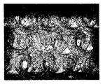
その結果を図6、7、8に示し、図6は本発明例、図7、8は従来例の加工面の状態である。2種類の本発明例は、凹状部4がギャッシュ部に開口するしないの差異はほとんど見られず、ともに工具摩耗状態が正常摩耗で摩耗幅も小さく、図6に示す通り切り屑の凝着が非常に少ない光沢面が得られ、加工面粗さが良好であったのに対し、従来例である凹状部4が無く、チゼル幅5がボール刃の半径の1%、即ち0.05mmのものは、チゼル部の強度不足によりカケが発生し、図7に示す通り仕上げ面粗さも粗い結果となり、チゼル幅5がボール刃の半径の3%、即ち0.15mm及び5%、即ち0.25mmのものは、強度的には十分であったが、切削加工中に生じる切り屑がチゼル部で押し潰され、図8に示す通り加工面に切り屑の凝着を生じ、ムシレた様な加工面状態であった。
【0020】
(実施例2)
次に、前記製作品と同様にチゼル幅5をボール刃の半径の2、3、5、10、15、20%、チゼルエッジ2の工具回転方向側にギャッシュに開口する略半楕円形状の凹状部4を有し、凹状部距離7を0.05mmに設定した5種類のボールエンドミルを製作し、前記同様の切削テストを行い、切削長100m時の加工面の状態を観察した。
【0021】
本発明例である3〜15%、即ち0.15〜0.75mmのものは、チゼル幅5が大きくなるに従って、チゼル長さ8が長くなり、徐々に切削抵抗が大きくなったが、加工面に影響はなく、切り屑の凝着が非常に少ない光沢面が得られ、加工面粗さも良好であった。また、比較例である20%、即ち1mmのものは、本発明例である15%、即ち0.75mmのものより急激に切削抵抗が増加し、ビビリ振動を生じ、ムシレた加工面状態となった。また、比較例であるチゼル幅5をボール刃の半径の2%、即ち0.1mmのものは、チゼル部の強度不足により、カケが発生し仕上げ面粗さも粗い結果となった。
【0022】
(実施例3)
次に、前記製作品と同様にチゼル幅5をボール刃の半径の5%、即ち0.25mm、チゼルエッジ2の工具回転方向側にギャッシュ部に開口する工具正面視で略半楕円形状凹状部4を有し、凹状部距離7を0.01、0.03、0.05、0.08、0.1、0.12、0.15mmに設定した7種類のボールエンドミルを製作し、前記同様の切削テストを行い、切削長100m時の工具摩耗状態と加工面の状態を観察した。
【0023】
本発明例である0.03〜0.12mmについては、0.12mmのもののチゼルエッジ2に僅かに溶着が認められたが、加工面に影響はなく、切り屑の凝着が非常に少ない光沢面が得られ、加工面粗さも良好であった。また、比較例である0.15mmのものになると、凹状部4の効果がほとんどなく、切削加工中に生じる切り屑がチゼル部で押し潰され、加工面に切り屑の凝着を生じ、ムシレた様な加工面状態であった。比較例である凹状部距離7が0.01mmのものは、チゼルエッジ2の一部にチッピングが認められ、工具回転中心付近が摩滅によりチゼルエッジ2自体がなくなり、平らな面状態となり、ムシレた加工面状態となった。
【0024】
(実施例4)
次に、前記製作品と同様にチゼル幅5をボール刃の半径の5%即ち0.25mm、チゼル内接円6の内側でチゼルエッジ2の工具回転方向側にギャッシュに開口する工具正面視で略半楕円形状の凹状部4を有し、凹状部距離7を0.05mmに設定し、更に凹状部深さ11、凹状部幅10、凹状部側面傾斜角12を変化させたものを製作し、前記同様の切削テストを行い、切削長200m時の工具摩耗状態と加工面の状態を観察した。その結果を表1に示す。
【0025】
【表1】

表1には、本発明例1である凹状部深さ11を0.3mm、凹状部幅10を0.5mm、凹状部側面傾斜角12を60°としたものを基準形状とし、本発明例2〜5は凹状部深さ11を0.05〜1mm、本発明例6〜10は凹状部幅10を0.1〜2mm、本発明例11〜14は凹状部側面傾斜角12を20〜90°に変化させたものである。
【0027】
表1より、本発明例1〜4に記したように凹状部深さを0.05mmから1mmまでの範囲で切削長300m迄、光沢面が得られ、本発明例5〜9に記したように、凹状部幅は0.3mm以上の範囲で切削長300m迄、光沢面が得られ、本発明例10〜14に記したように、凹状部側面角は40〜80°の範囲において、加工面の粗さ、工具寿命ともに向上することが解った。更に、凹状部幅は最大でも1.5mmあれば十分であり、凹状部幅を1.5mmより大きくしても、切り屑排出性に関して、更なる効果向上は認められなかった。
【0028】
【発明の効果】
上記説明したように、本願発明を適用することにより、加工面に切り屑が凝着し易い被削材においても良好な仕上げ加工面が得ることができ、且つ工具寿命が向上することができた。
【図面の簡単な説明】
【図1】図1は、本発明の一実施例であり、その正面図である。
【図2】図2は、図1のチゼル部の拡大図である。
【図3】図3は、図2のA−A’軸平行断面図である。
【図4】図4は、本発明の他の実施例であり、そのチゼル部の正面拡大図である。
【図5】図5は、従来の一例であり、そのチゼル部の正面拡大図である。
【図6】図6は、本発明の一実施例のテスト結果を示す説明図である。
【図7】図7は、従来の一例のテスト結果を示す説明図である。
【図8】図8は、他の従来例のテスト結果を示す説明図である。
【符号の説明】
1 ボ−ル刃
2 チゼルエッジ
3 アール部ギャッシュ
4 凹状部
5 チゼル幅
6 チゼル内接円
7 凹状部距離
8 チゼル長さ
9 チゼル角
10 凹状部幅
11 凹状部深さ
12 凹状部側面傾斜角[0001]
[Industrial application fields]
The present invention relates to an improvement of a ball end mill for finishing using a machine tool such as a machining center, and more particularly to a shape of a ball center portion of a ball end mill.
[0002]
[Prior art]
In the case of a ball end mill, the vicinity of the center of the ball is in the vicinity of the tool rotation axis, and the cutting speed is not sufficiently obtained. Particularly in the cutting of the bottom surface close to a flat surface, a portion having a chisel edge formed by the flank surfaces of the ball blades ( In the following, it is referred to as a chisel portion.) In this case, there is no escape space for chips generated by the chisel edge, and the chips are crushed between the chisel portion and the work surface and adhered to the work surface or welded to the chisel edge. However, the surface roughness of the bottom surface close to a flat surface, such as overcutting by forming the constituent cutting edge, missing the base material of the tool at the time of dropping by repeatedly welding and dropping, and forming a gusseted machining surface due to sharpness deterioration. Could not be obtained.
[0003]
Therefore, as an improvement for the purpose of improving the processed surface roughness of the bottom surface close to a flat surface, there is a finishing ball end mill disclosed in Japanese Patent Application Laid-Open No. 2000-233411, and the strength of the ball center portion of the ball end mill is increased. By increasing and improving chip discharge, chipping is prevented, the tool life is extended, and the finished surface roughness is improved.
[0004]
[Problems to be solved by the invention]
Usually, the chips cut by the ball blade are discharged through the rounded portion gasche of the ball blade, but the distance between the rounded portion gashes forming the ball blade in a front view of the tool (hereinafter referred to as chisel width). )) Inside the circle (hereinafter referred to as the chisel inscribed circle) does not intersect with the rounded portion gasche, there is no chip escape, and in consideration of chip discharge, the chisel width Setting is important.
[0005]
However, as described above, if the chisel width is increased, the inscribed circle of the chisel also increases, and there is a problem in chip dischargeability. If the chisel is decreased, the strength of the chisel portion is weak, and in particular, hardness represented by martensitic stainless steel. With a hard work material that exceeds HRC45 and easily welds and adheres, along with its hardness, it repeatedly welds and falls off on the cutting edge during cutting, and the tool base material is missing at the time of dropout. There was also a problem with the surface roughness.
[0006]
Further, in the finishing ball end mill disclosed in Japanese Patent Laid-Open No. 2000-233111, the interval between the planes including the rake face of the two
[0007]
Like the ball blade and outer peripheral blade, there is a degree of freedom in the design of the cutting edge, and there is no problem with a part that can secure a sufficient chip pocket while having the cutting edge strength, but it has a large negative rake angle and the cutting edge There was a problem in the shape of the center of the ball where the chisel edge, which has little design freedom, becomes the cutting edge.
[0008]
[Object of the present invention]
The present invention has been made based on the background as described above, and has a good chip discharge property and a work material on which a chip easily adheres to a work surface or a hard work with HRC 45 or higher. An object of the present invention is to provide a ball end mill capable of obtaining a good finished surface even in a material.
[0009]
[Means for Solving the Problems]
Therefore, the first aspect of the present invention is a ball end mill having two ball blades substantially symmetrically with respect to the tool axis, and has a chisel edge formed between the flank faces of the ball blades at the tip of the ball. and 3 to 15% of the radius of the ball cutting edge a distance therebetween in the rounded portion gash to form a ball cutting edge of the ball center by vision, the tool rotational direction of the chisel edge, recessed concave relative to the curved surface of該逃up surface It provided a concave portion serving as a site該逃up surface of the chisel edge near said has a concave portion at least the spacing of the rounded portion gash inside the circle to the diameter, the shortest distance between the concave portion and the chisel edge 0.03 It is a ball end mill characterized by a thickness of ˜0.12 mm.
According to a second aspect of the present invention, there is provided a ball end mill according to the first aspect of the present invention, wherein the depth of the concave portion is set to 0.05 mm to 1 mm.
A third aspect of the present invention is the ball end mill according to the first or second aspect of the present invention, wherein the width of the concave portion in the direction perpendicular to the chisel edge is 0.3 to 1.5 mm.
According to a fourth aspect of the present invention, in any one of the first to third aspects of the present invention, the shape of the concave portion is a cross-sectional view perpendicular to the chisel edge and parallel to the tool axis, and the side surface on the chisel edge side is 40 It is a ball end mill characterized by being inclined by -80 °.
In a fifth aspect of the present invention according to any one of the first to fourth aspects of the present invention, the tool is viewed from the front of the tool in the tool rotation direction side of the chisel edge within the range of the inscribed circle of the chisel without opening the concave portion to the gasche. A ball end mill having a substantially elliptical concave portion.
[0010]
When cutting a work material where chips are likely to adhere to the work surface, the strength that can withstand the loss of the base material of the tool at the time of welding and dropping due to repeated welding and dropping on the cutting edge during cutting, The shape which has both sharpness including the chip discharge | emission property which is in conflict with shape is required. Therefore, in the present invention, first, considering the strength, the chisel width is set to 3 to 15% of the radius of the ball blade. When the chisel width is less than 3% of the radius of the ball blade, the strength is insufficient, and when it exceeds 15%, the length of the chisel edge having a negative rake angle (hereinafter referred to as chisel length) becomes long. Or the angle formed by the ball blade and the chisel edge (hereinafter referred to as the chisel angle) becomes smaller, the former is more inferior in sharpness, and the latter is inferior in the strength of the joint between the ball blade and the chisel edge. It was set to 3 to 15% of the radius. Here, it is desirable that the chisel length is 0.3 to 0.6 mm and the chisel angle is 165 to 180 ° based on research by the inventors of the present application.
[0011]
In addition, by setting the chisel width to 3% or more of the radius of the ball blade, the strength of the center of the ball can be obtained. However, as described above, there is a problem with the chip discharging property. A concave portion (hereinafter referred to as a concave portion) with respect to the curved surface of the flank, at least inside the chisel inscribed circle from the surface, and the shortest distance between the concave portion and the chisel edge (hereinafter referred to as the concave portion) The distance is referred to as 0.03 to 0.12 mm.
[0012]
By applying the present invention, the chips generated at the chisel edge are sandwiched between the chisel portion and the work material, and are not crushed, but through the concave portion provided inside the chisel inscribed circle. Discharged. Here, the machining by the end mill is generally intermittent cutting, and the strength of the cutting edge is required more than that of continuous cutting, for example, a drill that performs cutting only in the longitudinal direction. When the concave portion distance is less than 0.03 mm, the cutting of the workpiece, which cannot withstand intermittent cutting, easily wears off the tip of the ball quickly and is likely to have chips adhering to the machining surface, is performed. In some cases, it may not be possible to maintain the strength to withstand the loss of the tool base material when it is welded and removed by repeated welding and dropping to the cutting edge. If it is larger than 0.12 mm, the effect of the concave part can be exhibited. In order to eliminate this, the concave portion distance was set to 0.03 to 0.12 mm.
[0013]
DETAILED DESCRIPTION OF THE INVENTION
By applying the present invention, it has become possible to have both strength and chip discharge properties that are opposite to each other, so that a good finished surface can be obtained even in a work material on which the chip tends to adhere to the processing surface. And the tool life could be improved. Here, it is not necessary to stop the chips on the concave portion, and it is sufficient that the chips can be discharged through the concave portion. Especially, in the vicinity of the ball center portion of the ball end mill, the gap between the work material and the
[0014]
In addition, as described above, it is advantageous for the strength of the ball center to make the concave portion shallow enough not to disturb chip discharge, and the gap between the work material and the ball blade is on the outer peripheral side from the tool axis portion. In consideration of the size of the chips, it is sufficient that the depth of the concave portion (hereinafter referred to as the concave portion depth) is 0.05 mm with respect to the curved surface of the flank. About 10% of the radius is desirable.
[0015]
Furthermore, in order to improve the flow of chips in the concave portion, the concave portion may be opened in a gash, and in the front view of the tool, the maximum width of the concave portion on the straight line passing through the center of the tool and in the direction perpendicular to the chisel edge (below) The width of the concave portion may be 0.3 to 1.5 mm, and the shape of the concave portion is perpendicular to the chisel edge and parallel to the tool axis. You may make it incline 40-80 degrees (henceforth a concave part side surface inclination angle).
[0016]
Furthermore, since the chip to be discharged becomes smaller as it approaches the center of the tool, the width of the concave portion and / or the depth of the concave portion is gradually reduced from the tool axis toward the
[0017]
Example 1
1, 2 and 3 show an embodiment of the present invention. A
[0018]
The cutting conditions were a martensitic stainless steel SUS420J2 quenching material equivalent to SUS420J2 (52HRC), the rotational speed was 12500 min −1 , the feed rate was 2.5 m / min, and the cutting amount was 0 in the axial direction. 0.2 mm in the pick direction, 0.2 mm in the pick direction, and bottom finish cutting was performed by dry using an air blower, and the state of tool wear and the state of the machined surface at a cutting length of 100 m were observed.
[0019]
The results are shown in FIGS. 6, 7, and 8, where FIG. 6 shows the state of the processed surface of the example of the present invention, and FIGS. In the two examples of the present invention, the difference that the
[0020]
(Example 2)
Next, in the same manner as in the above-mentioned product, the chisel width 5 is set to 2, 3, 5, 10, 15, 20% of the radius of the ball blade, and the substantially semi-elliptical concave portion that opens to the tool rotation direction side of the
[0021]
In the example of the present invention having 3 to 15%, that is, 0.15 to 0.75 mm, as the chisel width 5 is increased, the chisel length 8 is increased and the cutting resistance is gradually increased. The glossy surface with very little chip adhesion was obtained, and the surface roughness was good. Further, the comparative example of 20%, i.e. 1 mm, has a sharper increase in cutting resistance than the 15% example of the present invention, i.e., 0.75 mm. It was. Further, when the chisel width 5 as a comparative example was 2% of the radius of the ball blade, that is, 0.1 mm, chipping occurred due to insufficient strength of the chisel portion and the finished surface was rough.
[0022]
(Example 3)
Next, the chisel width 5 is set to 5% of the radius of the ball blade, that is, 0.25 mm, and the
[0023]
In the case of 0.03-0.12 mm, which is an example of the present invention, slight welding was observed on the
[0024]
Example 4
Next, the chisel width 5 is set to 5% of the radius of the ball blade, that is, 0.25 mm, as in the above-described product, and the tool is opened from the chisel inscribed
[0025]
[Table 1]
Table 1 shows an example of the present invention in which the
[0027]
From Table 1, as described in Invention Examples 1 to 4, a glossy surface was obtained with a concave portion depth ranging from 0.05 mm to 1 mm up to a cutting length of 300 m. As described in Invention Examples 5 to 9 In addition, a glossy surface is obtained with a concave portion width of 0.3 mm or more and a cutting length of 300 m, and as described in Examples 10 to 14 of the present invention, the side surface angle of the concave portion is 40 to 80 °. It was found that both surface roughness and tool life were improved. Furthermore, it is sufficient that the width of the concave portion is 1.5 mm at the maximum, and even if the width of the concave portion is larger than 1.5 mm, no further improvement in the effect on the chip discharging property is recognized.
[0028]
【The invention's effect】
As described above, by applying the present invention, it was possible to obtain a good finished surface even in a work material in which chips are likely to adhere to the processed surface, and to improve the tool life. .
[Brief description of the drawings]
FIG. 1 is a front view of an embodiment of the present invention.
FIG. 2 is an enlarged view of the chisel portion of FIG. 1;
FIG. 3 is a cross-sectional view taken along the line AA ′ in FIG. 2;
FIG. 4 is a front enlarged view of a chisel portion according to another embodiment of the present invention.
FIG. 5 is an enlarged front view of the chisel portion as an example of the prior art.
FIG. 6 is an explanatory diagram showing test results of an example of the present invention.
FIG. 7 is an explanatory diagram showing a conventional test result.
FIG. 8 is an explanatory diagram showing test results of another conventional example.
[Explanation of symbols]
DESCRIPTION OF
Claims (5)
Priority Applications (1)
| Application Number | Priority Date | Filing Date | Title |
|---|---|---|---|
| JP2001047571A JP4610102B2 (en) | 2001-02-23 | 2001-02-23 | Ball end mill |
Applications Claiming Priority (1)
| Application Number | Priority Date | Filing Date | Title |
|---|---|---|---|
| JP2001047571A JP4610102B2 (en) | 2001-02-23 | 2001-02-23 | Ball end mill |
Publications (2)
| Publication Number | Publication Date |
|---|---|
| JP2002254234A JP2002254234A (en) | 2002-09-10 |
| JP4610102B2 true JP4610102B2 (en) | 2011-01-12 |
Family
ID=18908974
Family Applications (1)
| Application Number | Title | Priority Date | Filing Date |
|---|---|---|---|
| JP2001047571A Expired - Fee Related JP4610102B2 (en) | 2001-02-23 | 2001-02-23 | Ball end mill |
Country Status (1)
| Country | Link |
|---|---|
| JP (1) | JP4610102B2 (en) |
Families Citing this family (4)
| Publication number | Priority date | Publication date | Assignee | Title |
|---|---|---|---|---|
| JP4677722B2 (en) * | 2004-02-13 | 2011-04-27 | 三菱マテリアル株式会社 | 3-flute ball end mill |
| US8585329B2 (en) | 2007-11-07 | 2013-11-19 | Toyota Jidosha Kabushiki Kaisha | Ball end mill |
| KR101548450B1 (en) | 2014-01-29 | 2015-08-28 | 한국야금 주식회사 | Ball end mill |
| JP7419060B2 (en) * | 2019-12-27 | 2024-01-22 | 日進工具株式会社 | ball end mill |
Citations (8)
| Publication number | Priority date | Publication date | Assignee | Title |
|---|---|---|---|---|
| JPS61141014U (en) * | 1985-02-22 | 1986-09-01 | ||
| JPH02114417U (en) * | 1989-02-27 | 1990-09-13 | ||
| JPH02114427U (en) * | 1989-03-01 | 1990-09-13 | ||
| JPH0360909A (en) * | 1989-07-28 | 1991-03-15 | Kobe Steel Ltd | Ball end mill |
| JPH04146017A (en) * | 1990-10-03 | 1992-05-20 | Fukuchi Kosakusho:Kk | End mill |
| WO2000003825A1 (en) * | 1998-07-15 | 2000-01-27 | Colvin Kevin F | Cutting tool point |
| JP2000117522A (en) * | 1998-10-09 | 2000-04-25 | Shinko Kobelco Tool Kk | Ball end mill |
| JP2001009624A (en) * | 1999-07-02 | 2001-01-16 | Hitachi Tool Engineering Ltd | End mill |
-
2001
- 2001-02-23 JP JP2001047571A patent/JP4610102B2/en not_active Expired - Fee Related
Patent Citations (8)
| Publication number | Priority date | Publication date | Assignee | Title |
|---|---|---|---|---|
| JPS61141014U (en) * | 1985-02-22 | 1986-09-01 | ||
| JPH02114417U (en) * | 1989-02-27 | 1990-09-13 | ||
| JPH02114427U (en) * | 1989-03-01 | 1990-09-13 | ||
| JPH0360909A (en) * | 1989-07-28 | 1991-03-15 | Kobe Steel Ltd | Ball end mill |
| JPH04146017A (en) * | 1990-10-03 | 1992-05-20 | Fukuchi Kosakusho:Kk | End mill |
| WO2000003825A1 (en) * | 1998-07-15 | 2000-01-27 | Colvin Kevin F | Cutting tool point |
| JP2000117522A (en) * | 1998-10-09 | 2000-04-25 | Shinko Kobelco Tool Kk | Ball end mill |
| JP2001009624A (en) * | 1999-07-02 | 2001-01-16 | Hitachi Tool Engineering Ltd | End mill |
Also Published As
| Publication number | Publication date |
|---|---|
| JP2002254234A (en) | 2002-09-10 |
Similar Documents
| Publication | Publication Date | Title |
|---|---|---|
| US8579556B2 (en) | Insert for drill, drill and method of cutting work material | |
| JP2004223642A (en) | Square end mill | |
| US20070172321A1 (en) | Ball endmill | |
| WO2016043098A1 (en) | Drill | |
| JP2003311524A (en) | Cemented carbide ball end mill | |
| JPWO2013035166A1 (en) | drill | |
| JP2018529535A (en) | Turning insert | |
| KR20150055118A (en) | Ball end mill and insert | |
| JP4975395B2 (en) | Ball end mill | |
| JP3581115B2 (en) | Ball end mill and processing method using the ball end mill | |
| JP4125909B2 (en) | Square end mill | |
| JP7137107B2 (en) | ball end mill | |
| JP2015062978A (en) | Ball end mill | |
| JP4610102B2 (en) | Ball end mill | |
| WO2018074542A1 (en) | Cutting insert and cutting edge-interchangeable rotary cutting tool | |
| JP2008012610A (en) | Cbn ball end mill | |
| EP3733334A1 (en) | Drill | |
| JP4097515B2 (en) | Ball end mill | |
| JP2000334614A (en) | Ball end mill for nonferrous metal | |
| JP3754010B2 (en) | Ball end mill | |
| JP4370966B2 (en) | Grooved tool | |
| KR102548078B1 (en) | Rotary cutting tool | |
| JPH06335816A (en) | Minimum diameter end mill | |
| JP2013013962A (en) | Cbn end mill | |
| JP3786188B2 (en) | Ball end mill |
Legal Events
| Date | Code | Title | Description |
|---|---|---|---|
| A621 | Written request for application examination |
Free format text: JAPANESE INTERMEDIATE CODE: A621 Effective date: 20071219 |
|
| A131 | Notification of reasons for refusal |
Free format text: JAPANESE INTERMEDIATE CODE: A131 Effective date: 20100413 |
|
| A977 | Report on retrieval |
Free format text: JAPANESE INTERMEDIATE CODE: A971007 Effective date: 20100415 |
|
| A521 | Written amendment |
Free format text: JAPANESE INTERMEDIATE CODE: A523 Effective date: 20100610 |
|
| A521 | Written amendment |
Free format text: JAPANESE INTERMEDIATE CODE: A523 Effective date: 20100610 |
|
| TRDD | Decision of grant or rejection written | ||
| A01 | Written decision to grant a patent or to grant a registration (utility model) |
Free format text: JAPANESE INTERMEDIATE CODE: A01 Effective date: 20101012 |
|
| A01 | Written decision to grant a patent or to grant a registration (utility model) |
Free format text: JAPANESE INTERMEDIATE CODE: A01 |
|
| A61 | First payment of annual fees (during grant procedure) |
Free format text: JAPANESE INTERMEDIATE CODE: A61 Effective date: 20101012 |
|
| FPAY | Renewal fee payment (event date is renewal date of database) |
Free format text: PAYMENT UNTIL: 20131022 Year of fee payment: 3 |
|
| R150 | Certificate of patent or registration of utility model |
Free format text: JAPANESE INTERMEDIATE CODE: R150 |
|
| S531 | Written request for registration of change of domicile |
Free format text: JAPANESE INTERMEDIATE CODE: R313531 |
|
| S533 | Written request for registration of change of name |
Free format text: JAPANESE INTERMEDIATE CODE: R313533 |
|
| R360 | Written notification for declining of transfer of rights |
Free format text: JAPANESE INTERMEDIATE CODE: R360 |
|
| R350 | Written notification of registration of transfer |
Free format text: JAPANESE INTERMEDIATE CODE: R350 |
|
| LAPS | Cancellation because of no payment of annual fees |