EP3540904B1 - Elektrischer ladeakku - Google Patents
Elektrischer ladeakku Download PDFInfo
- Publication number
- EP3540904B1 EP3540904B1 EP19162387.5A EP19162387A EP3540904B1 EP 3540904 B1 EP3540904 B1 EP 3540904B1 EP 19162387 A EP19162387 A EP 19162387A EP 3540904 B1 EP3540904 B1 EP 3540904B1
- Authority
- EP
- European Patent Office
- Prior art keywords
- electric charge
- electric
- fact
- charge accumulator
- amount
- Prior art date
- Legal status (The legal status is an assumption and is not a legal conclusion. Google has not performed a legal analysis and makes no representation as to the accuracy of the status listed.)
- Not-in-force
Links
Images


Classifications
-
- H—ELECTRICITY
- H02—GENERATION; CONVERSION OR DISTRIBUTION OF ELECTRIC POWER
- H02J—ELECTRIC POWER NETWORKS; CIRCUIT ARRANGEMENTS OR SYSTEMS FOR SUPPLYING OR DISTRIBUTING ELECTRIC POWER; SYSTEMS FOR STORING ELECTRIC ENERGY
- H02J7/00—Circuit arrangements for charging or discharging batteries or for supplying loads from batteries
- H02J7/80—Circuit arrangements for charging or discharging batteries or for supplying loads from batteries including monitoring or indicating arrangements
-
- B—PERFORMING OPERATIONS; TRANSPORTING
- B60—VEHICLES IN GENERAL
- B60L—PROPULSION OF ELECTRICALLY-PROPELLED VEHICLES; SUPPLYING ELECTRIC POWER FOR AUXILIARY EQUIPMENT OF ELECTRICALLY-PROPELLED VEHICLES; ELECTRODYNAMIC BRAKE SYSTEMS FOR VEHICLES IN GENERAL; MAGNETIC SUSPENSION OR LEVITATION FOR VEHICLES; MONITORING OPERATING VARIABLES OF ELECTRICALLY-PROPELLED VEHICLES; ELECTRIC SAFETY DEVICES FOR ELECTRICALLY-PROPELLED VEHICLES
- B60L58/00—Methods or circuit arrangements for monitoring or controlling batteries or fuel cells, specially adapted for electric vehicles
- B60L58/10—Methods or circuit arrangements for monitoring or controlling batteries or fuel cells, specially adapted for electric vehicles for monitoring or controlling batteries
-
- H—ELECTRICITY
- H01—ELECTRIC ELEMENTS
- H01M—PROCESSES OR MEANS, e.g. BATTERIES, FOR THE DIRECT CONVERSION OF CHEMICAL ENERGY INTO ELECTRICAL ENERGY
- H01M10/00—Secondary cells; Manufacture thereof
- H01M10/06—Lead-acid accumulators
-
- H—ELECTRICITY
- H01—ELECTRIC ELEMENTS
- H01M—PROCESSES OR MEANS, e.g. BATTERIES, FOR THE DIRECT CONVERSION OF CHEMICAL ENERGY INTO ELECTRICAL ENERGY
- H01M10/00—Secondary cells; Manufacture thereof
- H01M10/42—Methods or arrangements for servicing or maintenance of secondary cells or secondary half-cells
- H01M10/425—Structural combination with electronic components, e.g. electronic circuits integrated to the outside of the casing
-
- H—ELECTRICITY
- H01—ELECTRIC ELEMENTS
- H01M—PROCESSES OR MEANS, e.g. BATTERIES, FOR THE DIRECT CONVERSION OF CHEMICAL ENERGY INTO ELECTRICAL ENERGY
- H01M10/00—Secondary cells; Manufacture thereof
- H01M10/42—Methods or arrangements for servicing or maintenance of secondary cells or secondary half-cells
- H01M10/48—Accumulators combined with arrangements for measuring, testing or indicating the condition of cells, e.g. the level or density of the electrolyte
- H01M10/484—Accumulators combined with arrangements for measuring, testing or indicating the condition of cells, e.g. the level or density of the electrolyte for measuring electrolyte level, electrolyte density or electrolyte conductivity
-
- H—ELECTRICITY
- H01—ELECTRIC ELEMENTS
- H01M—PROCESSES OR MEANS, e.g. BATTERIES, FOR THE DIRECT CONVERSION OF CHEMICAL ENERGY INTO ELECTRICAL ENERGY
- H01M50/00—Constructional details or processes of manufacture of the non-active parts of electrochemical cells other than fuel cells, e.g. hybrid cells
- H01M50/60—Arrangements or processes for filling or topping-up with liquids; Arrangements or processes for draining liquids from casings
- H01M50/609—Arrangements or processes for filling with liquid, e.g. electrolytes
- H01M50/627—Filling ports
-
- H—ELECTRICITY
- H01—ELECTRIC ELEMENTS
- H01M—PROCESSES OR MEANS, e.g. BATTERIES, FOR THE DIRECT CONVERSION OF CHEMICAL ENERGY INTO ELECTRICAL ENERGY
- H01M10/00—Secondary cells; Manufacture thereof
- H01M10/42—Methods or arrangements for servicing or maintenance of secondary cells or secondary half-cells
- H01M10/425—Structural combination with electronic components, e.g. electronic circuits integrated to the outside of the casing
- H01M2010/4271—Battery management systems including electronic circuits, e.g. control of current or voltage to keep battery in healthy state, cell balancing
-
- H—ELECTRICITY
- H01—ELECTRIC ELEMENTS
- H01M—PROCESSES OR MEANS, e.g. BATTERIES, FOR THE DIRECT CONVERSION OF CHEMICAL ENERGY INTO ELECTRICAL ENERGY
- H01M2220/00—Batteries for particular applications
- H01M2220/20—Batteries in motive systems, e.g. vehicle, ship, plane
-
- Y—GENERAL TAGGING OF NEW TECHNOLOGICAL DEVELOPMENTS; GENERAL TAGGING OF CROSS-SECTIONAL TECHNOLOGIES SPANNING OVER SEVERAL SECTIONS OF THE IPC; TECHNICAL SUBJECTS COVERED BY FORMER USPC CROSS-REFERENCE ART COLLECTIONS [XRACs] AND DIGESTS
- Y02—TECHNOLOGIES OR APPLICATIONS FOR MITIGATION OR ADAPTATION AGAINST CLIMATE CHANGE
- Y02E—REDUCTION OF GREENHOUSE GAS [GHG] EMISSIONS, RELATED TO ENERGY GENERATION, TRANSMISSION OR DISTRIBUTION
- Y02E60/00—Enabling technologies; Technologies with a potential or indirect contribution to GHG emissions mitigation
- Y02E60/10—Energy storage using batteries
-
- Y—GENERAL TAGGING OF NEW TECHNOLOGICAL DEVELOPMENTS; GENERAL TAGGING OF CROSS-SECTIONAL TECHNOLOGIES SPANNING OVER SEVERAL SECTIONS OF THE IPC; TECHNICAL SUBJECTS COVERED BY FORMER USPC CROSS-REFERENCE ART COLLECTIONS [XRACs] AND DIGESTS
- Y02—TECHNOLOGIES OR APPLICATIONS FOR MITIGATION OR ADAPTATION AGAINST CLIMATE CHANGE
- Y02T—CLIMATE CHANGE MITIGATION TECHNOLOGIES RELATED TO TRANSPORTATION
- Y02T10/00—Road transport of goods or passengers
- Y02T10/60—Other road transportation technologies with climate change mitigation effect
- Y02T10/70—Energy storage systems for electromobility, e.g. batteries
Definitions
- the present invention relates to an electric charge accumulator.
- charge accumulators and traction batteries are used to provide power for the movement of vehicles, such as electric cars, motors for trailers, pallet trucks, forklift trucks and the like.
- traction battery One type of traction battery that is generally used consists of flooded batteries, which represent a particular category of lead-acid accumulators, which are among the most popular accumulators on the market and represent a widely tested technology.
- They consist of two lead electrodes or plates, in particular one lead electrode and one lead dioxide electrode, immersed in an aqueous electrolytic solution of sulphuric acid at fixed concentration.
- the exceeding energy supplied to the system during the charge accumulation phase causes the electrolysis of the water of the electrolytic solution, with the formation of hydrogen and oxygen.
- This reaction tends to self-support by raising the temperature due to the passage of the current and contributes to the evaporation of water of the electrolytic solution, increasing the concentration of sulphuric acid in the solution and leaving the plates uncovered.
- the accumulators of this type are provided with introduction openings for the periodic topping up of water, so as to maintain the correct level of aqueous solution and not leave the plates uncovered.
- Some electric charge accumulators are also provided with a level probe, i.e. a lead rod which, being positioned vertically and immersed in the electrolytic solution, measures the level thereof.
- a level probe i.e. a lead rod which, being positioned vertically and immersed in the electrolytic solution, measures the level thereof.
- This probe on the contrary, being immersed in a highly aggressive solution, tends to oxidize and to undergo sulfation, so it should be periodically disassembled and cleaned.
- Transport and lifting vehicles such as forklift trucks and pallet trucks, are often hired from suppliers, and it often happens that operators neglect to maintain the electric charge accumulator, with a consequent increase in the occurrence of breakdowns and deteriorations, which cause the increase in the costs of replacing the accumulator.
- US9893391B1 discloses an electric battery for a vehicle.
- the main aim of the present invention is to devise an electric charge accumulator that allows avoiding the risk of failure and breakage during use, providing information on the maintenance to be carried out.
- one object of the present invention is to allow real-time monitoring of the level of electrolytic solution inside the electric charge accumulator.
- a further object of the present invention is to allow the performance improvement of the electric charge accumulator.
- Another object of the present invention is to allow the increase in the average lifespan of the electric charge accumulator itself.
- Another object of the present invention is to devise an electric charge accumulator that allows overcoming the mentioned drawbacks of the prior art in a simple, rational, easy, effective to use and cost effective solution.
- reference numeral 1 globally indicates an electric charge accumulator.
- the electric charge accumulator 1 comprises at least one flooded electric battery 2 containing at least one electrolytic solution comprising water and mounted on board a vehicle, for the power supply of the vehicle itself, wherein such an electric battery has a predetermined operating time capacity L a .
- the flooded electric battery 2 is a particular type of lead-acid battery, which contains the aqueous electrolytic solution of sulphuric acid at fixed concentration within a range established by the manufacturer, within which two lead electrodes are immersed.
- the heat produced during operation causes the evaporation of the water contained in the electrolytic solution.
- Such a flooded electric battery 2 is not however hermetically sealed with respect to the external environment, so that the evaporated water escapes from the electric battery itself, thus causing a change in the amount of electrolytic solution, resulting in increased concentration during use.
- this type of device In order to keep the amount and concentration of the electrolytic solution within the established values, this type of device, therefore, requires the periodic replenishment of the evaporated water, which can be carried out through the topping up openings made on the electric battery 2 that are closed through the plugs, to prevent the accidental leakage of the liquid.
- the concentration of the electrolytic solution reaches such high levels that lead sulphate is deposited on the electrodes, the lead sulphate being formed by the electrolytic reactions that take place inside the electric battery 2.
- This phenomenon is called sulphation and consists in the formation of a crystalline layer of lead sulphate which causes a significant increase in the internal electric resistance, with a consequent increase in the voltage drop inside the electric battery 2 and malfunction of the same.
- the predetermined operating time capacity L a coincides with the maximum volume of water that can evaporate during operation so that the concentration values of the electrolytic solution remain within the desired range, so this is a figure provided for by the manufacturer.
- the electric charge accumulator 1 usefully comprises at least one charging plane on which the electric battery 2 rests, which is held in place by means of fastening means, so as to have a stable support during use, while the charging plane itself is anchored to the vehicle floor.
- the electric charge accumulator 1 comprises acquisition means 3 for acquiring the current electric charge C n delivered by the electric battery 2 in a current cycle of use.
- cycle of use mean the series of operations that take place between the beginning of the use of the electric battery 2 to power the vehicle and the topping up of water which is necessary for the correct operation of the electric battery itself.
- the electric battery 2 is able to deliver a limited electric charge that allows the vehicle to be powered for a limited period of time.
- the acquisition means 3 allow, therefore, measuring the electric charge delivered by the electric battery 2 in the current cycle of use, acquiring the value of the current electric charge C n .
- the electric charge accumulator 1 comprises detection means 4 for detecting the previous electric charge C n-1 delivered by the electric battery 2 in a previous cycle of use.
- the detection means 4 allow storing the amount of water introduced and the electric charge delivered by the electric battery 2 in the previous cycle of use, so as to make the data available for the subsequent cycles.
- the acquisition means 3 coincide with the detection means 4, although the possibility of providing acquisition means 3 and separate detection means cannot be ruled out.
- the electric charge accumulator 1 comprises measurement means 5 for measuring the amount of water introduced L n-1 in the electric battery 2 for the replenishment of the electrolytic solution after the previous cycle of use.
- these measurement means 5 allow calculating the water introduced into the electric battery 2 in order to monitor the amount of water evaporated during the operation of the electric battery itself.
- the measurement means 5 comprise at least one flow rate measuring device 6 for measuring the water introduced into the electric battery 2 which is adapted to measure the flow rate introduced into the electric battery itself at the end of each cycle of use, although the possibility of providing for different types of measurement means 5 cannot be ruled out.
- the use of the flow rate measuring device 6 implies that the amount of water introduced L n-1 coincides with the flow rate of water introduced into the electric battery 2 after a previous cycle of use.
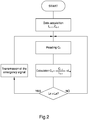
- the electric charge accumulator 1 comprises processing means 7 operatively connected to the acquisition means 3, to the detection means 4 and to the measurement means 5 and adapted to calculate, depending on the current electric charge C n , the previous electric charge C n-1 , the amount of water introduced L n-1 and the predetermined operating time capacity L a , at least one of a first representative quantity of the consumption of water in the current cycle of use and a second representative quantity of the operating time of the electric battery 2 in the current cycle of use.
- the first quantity is an estimate of the amount of water consumed L n by the electric battery 2 in the current cycle of use and the second quantity is coincident with the predetermined operating time capacity L a .
- the amount of water to be introduced L n at the end of the current cycle of use is equivalent to the amount of water evaporated during the current cycle of use itself.
- the amount of water to be introduced L n i.e. the quantity of water evaporated, is lower than the predetermined operating time capacity L a , so as not to risk to leave the plates uncovered and undergo sulphation.
- the ratio between the current electric charge C n and the previous electric charge C n-1 is used in the current cycle of use as a correction factor for measuring the amount of water introduced L n-1 so as to take into account the statistics of the charge delivered by the electric battery 2.
- This measure makes it possible to obtain an electric charge accumulator 1 in which the evolution of the efficiency of the electric battery 2 is taken into account, which efficiency may vary over time due to wear.
- the first quantity is coincident with the current electric charge C n and the second quantity is an estimate of the operating time electric charge C a of the electric battery 2 in the current cycle of use.
- the operating time electric charge C a delivered in the current cycle of use is representative of the total operating time of the electric battery 2 in the cycle of use itself.
- the electric battery 2 is capable of delivering a certain electric charge, which causes the evaporation of a respective amount of water from the electrolytic solution.
- the maximum amount of electric charge that can be delivered by the electric battery 2 so that the level of the electrolytic solution is sufficient to ensure the correct operation of the electric charge accumulator 1 is the one that involves the evaporation of an amount of water equal to the predetermined operating time capacity L a , that is the operating time electric charge C a .
- the operating time electric charge C a must be higher than the current electric charge C n measured in the current cycle of use.
- the electric charge accumulator 1 comprises generation means 8 for generating one emergency electronic signal which are operatively connected to the processing means 7.
- processing means 7 and the generation means 8 into a single processing unit, such as e.g. one electronic control unit or the like, cannot be ruled out.
- These generation means 8 are activated by the processing means 7 when the value of the first quantity is substantially higher than the value of the second quantity, which is a dangerous condition because the electric battery 2 could break and the vehicle could be damaged, resulting in damages of the economic nature.
- the electric charge accumulator 1 comprises at least one long-range transmission device 9 operatively connected to the generation means 8 and adapted to receive the emergency electronic signal and to emit at least one long-range electronic signal for the data transmission.
- the emergency electronic signal therefore, allows the operator to be informed about the potential danger condition and the need to top up the water inside the electric battery 2.
- the electric charge accumulator 1 also comprises at least one user interface 10 downloaded onto at least one of a mobile device and a computer and adapted to receive the long-range electronic signal for the provision of data and for data processing.
- This user interface 10 comprises storage means which are adapted to record the data provided over time, in order to carry out a statistical analysis of the variation of the electric charge delivered and of the amount of water introduced for each cycle of use.
- the operator may have real time access to the data relative to the first quantity and to the second quantity sent by the long-range transmission device 9.
- the electric charge accumulator 1 comprises at least one short-range transmission device 11 operatively connected to the generation means 8 and adapted to receive the emergency electronic signal and to emit at least one short-range electronic signal for the activation of at least one of a visual signaling device 12 and an acoustic signaling device 13 arranged in the proximity of the electric battery 2, such as e.g. on board the vehicle.
- the visual signaling device 12 and the acoustic signaling device 13 are means of communication of the emergency condition and allow drawing the attention of the operator.
- the electric charge accumulator 1 usefully comprises blocking means 14 for blocking the vehicle which are operatively connected to the generation means 8 and adapted to prevent the vehicle itself from starting when the value of the first quantity is substantially higher than the value of the second quantity.
- the generation means 8 provide an electronic alarm signal to the blocking means 14, which, by activating, prevent the vehicle from starting until the level of the electrolytic solution inside the electric battery 2 has been replenished.
- This measure ensures that the electric charge accumulator 1 will not be used unless the minimum conditions for its proper operation are met. It also prevents possible vehicle breakdowns due to a possible short circuit of the electric battery 2.
- the special measure of providing short-range transmission means connected to visual and acoustic signaling devices allows the operator to be warned of the emergency condition so as to carry out the necessary maintenance.
- the special measure of providing acquisition means for acquiring the current charge, detection means for detecting the electric charge of an electric battery and measurement means for measuring the amount of water introduced allows monitoring the level of electrolytic solution in real time.
- the special measure of providing long-range transmission means connected to a user interface for the statistical processing of the measurements made makes it possible to draw up a maintenance plan that makes it possible to increase the average lifespan of the electric charge accumulator and improve its performance.
Landscapes
- Engineering & Computer Science (AREA)
- Chemical & Material Sciences (AREA)
- Chemical Kinetics & Catalysis (AREA)
- Electrochemistry (AREA)
- General Chemical & Material Sciences (AREA)
- Manufacturing & Machinery (AREA)
- Power Engineering (AREA)
- Sustainable Development (AREA)
- Life Sciences & Earth Sciences (AREA)
- Sustainable Energy (AREA)
- Transportation (AREA)
- Mechanical Engineering (AREA)
- Microelectronics & Electronic Packaging (AREA)
- Secondary Cells (AREA)
- Charge And Discharge Circuits For Batteries Or The Like (AREA)
- Supply Devices, Intensifiers, Converters, And Telemotors (AREA)
- Laying Of Electric Cables Or Lines Outside (AREA)
- Emergency Protection Circuit Devices (AREA)
Claims (10)
- Elektrischer Ladungsakkumulator (1), umfassend:- mindestens eine geflutete elektrische Batterie (2), die mindestens eine Elektrolytlösung enthält, die Wasser umfasst und an Bord eines Fahrzeugs für die Stromversorgung des Fahrzeugs montierbar ist, wobei die elektrische Batterie (2) eine vorbestimmte Betriebszeitkapazität (La) aufweist; dadurch gekennzeichnet, dass sie umfasst:- Erfassungsmittel (3) zum Erfassen der aktuellen elektrischen Ladung (Cn), die von der elektrischen Batterie (2) in einem aktuellen Nutzungszyklus geliefert wird;- Erkennungsmittel (4) zum Erkennen der vorhergehenden elektrischen Ladung (Cn-1), die von der elektrischen Batterie (2) in einem vorhergehenden Nutzungszyklus abgegeben wurde;- Messmittel (5) zum Messen der Wassermenge (Ln-1), die in die elektrische Batterie (2) zur Wiederherstellung der elektrolytischen Lösung nach dem vorhergehenden Verwendungszyklus eingeleitet wird;- Verarbeitungsmittel (7), die operativ mit den Erfassungsmitteln (3), den Erkennungsmitteln (4) und den Messmitteln (5) verbunden sind und geeignet sind, in Abhängigkeit von der aktuellen elektrischen Ladung (Cn), der vorherigen elektrischen Ladung (Cn-1), der eingeleiteten Wassermenge (Ln-1) und der vorbestimmten Betriebszeitkapazität (La) mindestens eine erste repräsentative Größe des Wasserverbrauchs im aktuellen Nutzungszyklus und eine zweite repräsentative Größe der Betriebszeit der elektrischen Batterie (2) im aktuellen Nutzungszyklus zu berechnen;- Erzeugungsmittel (8) zum Erzeugen mindestens eines elektronischen Notsignals, die betriebsmäßig mit den Verarbeitungsmitteln (7) verbunden sind, wobei die Erzeugungsmittel (8) aktiviert werden, wenn der Wert der ersten Größe wesentlich höher ist als der Wert der zweiten Größe.
- Elektrischer Ladungsakkumulator (1) nach Anspruch 1, dadurch gekennzeichnet, dass die erste Größe eine Schätzung der Wassermenge (Ln) ist, die von der elektrischen Batterie (2) in dem aktuellen Nutzungszyklus verbraucht wird, und dass die zweite Größe mit der vorbestimmten Betriebszeitkapazität (La) zusammenfällt.
- Elektrischer Ladungsakkumulator (1) nach Anspruch 2, dadurch gekennzeichnet, dass die Verarbeitungsmittel (7) so ausgelegt sind, die Menge des einzuleitenden Wassers (Ln) mit Hilfe der folgenden Formel zu berechnen:
 (Cn) die aktuelle elektrische Ladung ist;(Cn-1) die vorherige elektrische Ladung ist;(Ln-1) die eingeleitete Wassermenge ist.
 - Elektrischer Ladungsakkumulator (1) nach Anspruch 1, dadurch gekennzeichnet, dass die erste Größe mit der aktuellen elektrischen Ladung (Cn) zusammenfällt und die zweite Größe eine Schätzung der elektrischen Ladung (Ca) der elektrischen Batterie (2) während der Betriebszeit in dem aktuellen Nutzungszyklus ist.
- Elektrischer Ladungsakkumulator (1) nach Anspruch 4, dadurch gekennzeichnet, dass die Verarbeitungsmittel (7) so ausgelegt sind, die elektrische Ladung (Ca) während der Betriebszeit mit Hilfe der folgenden Formel zu berechnen
 (Cn-1) die vorherige elektrische Ladung ist;(Ln-1) die eingeleitete Wassermenge ist;(La) die vorgegebene Betriebszeitkapazität ist.
 - Elektrischer Ladungsakkumulator (1) nach einem oder mehreren der vorhergehenden Ansprüche, dadurch gekennzeichnet, dass er mindestens eine Übertragungsvorrichtung (9) mit großer Reichweite umfasst, die funktionell mit den Erzeugungsmitteln (8) verbunden ist und geeignet ist, das elektronische Notsignal zu empfangen und mindestens ein elektronisches Signal mit großer Reichweite für die Datenübertragung auszusenden.
- Elektrischer Ladungsakkumulator (1) nach einem oder mehreren der vorhergehenden Ansprüche, dadurch gekennzeichnet, dass er mindestens eine Benutzerschnittstelle umfasst, die auf mindestens eines von einem mobilen Gerät und einem Computer geladen ist und geeignet ist, das elektronische Signal mit großer Reichweite für die Bereitstellung von Daten zu empfangen und die Daten zu verarbeiten.
- Elektrischer Ladungsakkumulator (1) nach einem oder mehreren der vorhergehenden Ansprüche, dadurch gekennzeichnet, dass die Benutzerschnittstelle Speichermittel umfasst, die geeignet sind, die Daten im Laufe der Zeit für die statistische Analyse der Veränderung der eingeleiteten Wassermenge (Ln-1) aufzuzeichnen.
- Elektrischer Ladungsakkumulator (1) nach einem oder mehreren der vorhergehenden Ansprüche, dadurch gekennzeichnet, dass er mindestens eine Übertragungsvorrichtung mit kurzer Reichweite (11) umfasst, die funktionell mit den Erzeugungsmitteln (8) verbunden ist und geeignet ist, das elektronische Notsignal zu empfangen und mindestens ein elektronisches Signal mit kurzer Reichweite zur Aktivierung mindestens eines von einer optischen Signalvorrichtung (12) und einer akustischen Signalvorrichtung (13) auszusenden, die in der Nähe der elektrischen Batterie (2) angeordnet sind.
- Elektrischer Ladungsakkumulator (1) nach einem oder mehreren der vorhergehenden Ansprüche, dadurch gekennzeichnet, dass er Blockiermittel (14) umfasst, um das Fahrzeug zu blockieren, wenn es betriebsmäßig mit den Erzeugungsmitteln (8) verbunden ist, und die geeignet sind, das Fahrzeug, wenn es angeschlossen ist, am Starten zu hindern, wenn der Wert der ersten Größe wesentlich höher ist als der Wert der zweiten Größe.
Applications Claiming Priority (1)
| Application Number | Priority Date | Filing Date | Title |
|---|---|---|---|
| IT102018000003512A IT201800003512A1 (it) | 2018-03-13 | 2018-03-13 | Accumulatore di carica elettrica |
Publications (2)
| Publication Number | Publication Date |
|---|---|
| EP3540904A1 EP3540904A1 (de) | 2019-09-18 |
| EP3540904B1 true EP3540904B1 (de) | 2020-12-30 |
Family
ID=62530355
Family Applications (1)
| Application Number | Title | Priority Date | Filing Date |
|---|---|---|---|
| EP19162387.5A Not-in-force EP3540904B1 (de) | 2018-03-13 | 2019-03-12 | Elektrischer ladeakku |
Country Status (2)
| Country | Link |
|---|---|
| EP (1) | EP3540904B1 (de) |
| IT (1) | IT201800003512A1 (de) |
Family Cites Families (2)
| Publication number | Priority date | Publication date | Assignee | Title |
|---|---|---|---|---|
| ZA762221B (en) * | 1975-04-24 | 1977-04-27 | Lucas Batteries Ltd | Topping-up of electric storage batteries |
| US9893391B1 (en) * | 2013-09-23 | 2018-02-13 | Pacific Steamex Cleaning Systems, Inc. | Battery water level detector for a battery operated device |
-
2018
- 2018-03-13 IT IT102018000003512A patent/IT201800003512A1/it unknown
-
2019
- 2019-03-12 EP EP19162387.5A patent/EP3540904B1/de not_active Not-in-force
Non-Patent Citations (1)
| Title |
|---|
| None * |
Also Published As
| Publication number | Publication date |
|---|---|
| EP3540904A1 (de) | 2019-09-18 |
| IT201800003512A1 (it) | 2019-09-13 |
Similar Documents
| Publication | Publication Date | Title |
|---|---|---|
| JP7670769B2 (ja) | リアルタイム電池故障検出及び健全性状態監視 | |
| TWI444639B (zh) | Battery performance monitoring | |
| US9509011B2 (en) | Method and system for rebalancing electrolytes in a redox flow battery system | |
| KR101663579B1 (ko) | 배터리 모니터링 장치 및 이를 이용한 배터리 모니터링 시스템 | |
| US9182451B2 (en) | System and method for posteriori adaptation of a state of charge model in a battery | |
| JP4864383B2 (ja) | 蓄電デバイスの劣化状態推定装置 | |
| JP2011112453A (ja) | 蓄電池のセル短絡検知方法及び検知装置 | |
| KR101708457B1 (ko) | 이차 전지의 건강 상태 추정 장치 및 방법 | |
| CN109143101A (zh) | 一种汽车蓄电池状态监测警示系统及方法 | |
| US20090226769A1 (en) | Measurement of insulation resistance of fuel cell in fuel cell system | |
| CN111061238A (zh) | 锂电池的生产安全监测方法、装置、设备及介质 | |
| WO2021066128A1 (ja) | 推定装置、推定方法、及びコンピュータプログラム | |
| US11604225B2 (en) | Method for estimating state of charge, liquid reduction amount of electrolyte solution of valve regulated lead-acid battery, and device for monitoring valve regulated lead-acid | |
| EP3540904B1 (de) | Elektrischer ladeakku | |
| JP2020184474A (ja) | 鉛蓄電池のメンテナンスシステム | |
| CN203519727U (zh) | 蓄电池内阻在线被动检测系统 | |
| JP4413893B2 (ja) | 蓄電池の制御方法及び制御装置 | |
| CN105161781A (zh) | 一种铅酸蓄电池充放电管理的控制方法 | |
| JP2021061119A (ja) | 推定装置、推定方法及びコンピュータプログラム | |
| JPH0689745A (ja) | 二次電池システム | |
| KR20140087995A (ko) | 전동장치용 배터리의 전력모니터링 시스템 | |
| JP5031231B2 (ja) | 放電時間算出装置及び放電時間算出方法 | |
| CN117937653A (zh) | 一种蓄电池寿命监控系统及方法 | |
| GB2551139A (en) | Methods and apparatus for monitoring electricity storage systems | |
| JP5359512B2 (ja) | エンジン始動用の蓄電池の状態表示装置 |
Legal Events
| Date | Code | Title | Description |
|---|---|---|---|
| PUAI | Public reference made under article 153(3) epc to a published international application that has entered the european phase |
Free format text: ORIGINAL CODE: 0009012 |
|
| STAA | Information on the status of an ep patent application or granted ep patent |
Free format text: STATUS: THE APPLICATION HAS BEEN PUBLISHED |
|
| AK | Designated contracting states |
Kind code of ref document: A1 Designated state(s): AL AT BE BG CH CY CZ DE DK EE ES FI FR GB GR HR HU IE IS IT LI LT LU LV MC MK MT NL NO PL PT RO RS SE SI SK SM TR |
|
| AX | Request for extension of the european patent |
Extension state: BA ME |
|
| STAA | Information on the status of an ep patent application or granted ep patent |
Free format text: STATUS: REQUEST FOR EXAMINATION WAS MADE |
|
| 17P | Request for examination filed |
Effective date: 20200316 |
|
| RBV | Designated contracting states (corrected) |
Designated state(s): AL AT BE BG CH CY CZ DE DK EE ES FI FR GB GR HR HU IE IS IT LI LT LU LV MC MK MT NL NO PL PT RO RS SE SI SK SM TR |
|
| GRAP | Despatch of communication of intention to grant a patent |
Free format text: ORIGINAL CODE: EPIDOSNIGR1 |
|
| STAA | Information on the status of an ep patent application or granted ep patent |
Free format text: STATUS: GRANT OF PATENT IS INTENDED |
|
| RIC1 | Information provided on ipc code assigned before grant |
Ipc: H01M 10/48 20060101ALI20200702BHEP Ipc: H01M 10/06 20060101ALI20200702BHEP Ipc: H01M 10/42 20060101ALI20200702BHEP Ipc: H01M 2/36 20060101ALI20200702BHEP Ipc: B60L 58/10 20190101ALI20200702BHEP Ipc: H02J 7/00 20060101AFI20200702BHEP |
|
| INTG | Intention to grant announced |
Effective date: 20200724 |
|
| GRAS | Grant fee paid |
Free format text: ORIGINAL CODE: EPIDOSNIGR3 |
|
| GRAA | (expected) grant |
Free format text: ORIGINAL CODE: 0009210 |
|
| STAA | Information on the status of an ep patent application or granted ep patent |
Free format text: STATUS: THE PATENT HAS BEEN GRANTED |
|
| AK | Designated contracting states |
Kind code of ref document: B1 Designated state(s): AL AT BE BG CH CY CZ DE DK EE ES FI FR GB GR HR HU IE IS IT LI LT LU LV MC MK MT NL NO PL PT RO RS SE SI SK SM TR |
|
| REG | Reference to a national code |
Ref country code: GB Ref legal event code: FG4D |
|
| REG | Reference to a national code |
Ref country code: AT Ref legal event code: REF Ref document number: 1350898 Country of ref document: AT Kind code of ref document: T Effective date: 20210115 |
|
| REG | Reference to a national code |
Ref country code: DE Ref legal event code: R096 Ref document number: 602019001926 Country of ref document: DE |
|
| REG | Reference to a national code |
Ref country code: IE Ref legal event code: FG4D |
|
| PG25 | Lapsed in a contracting state [announced via postgrant information from national office to epo] |
Ref country code: GR Free format text: LAPSE BECAUSE OF FAILURE TO SUBMIT A TRANSLATION OF THE DESCRIPTION OR TO PAY THE FEE WITHIN THE PRESCRIBED TIME-LIMIT Effective date: 20210331 Ref country code: NO Free format text: LAPSE BECAUSE OF FAILURE TO SUBMIT A TRANSLATION OF THE DESCRIPTION OR TO PAY THE FEE WITHIN THE PRESCRIBED TIME-LIMIT Effective date: 20210330 Ref country code: RS Free format text: LAPSE BECAUSE OF FAILURE TO SUBMIT A TRANSLATION OF THE DESCRIPTION OR TO PAY THE FEE WITHIN THE PRESCRIBED TIME-LIMIT Effective date: 20201230 Ref country code: FI Free format text: LAPSE BECAUSE OF FAILURE TO SUBMIT A TRANSLATION OF THE DESCRIPTION OR TO PAY THE FEE WITHIN THE PRESCRIBED TIME-LIMIT Effective date: 20201230 |
|
| REG | Reference to a national code |
Ref country code: AT Ref legal event code: MK05 Ref document number: 1350898 Country of ref document: AT Kind code of ref document: T Effective date: 20201230 |
|
| PG25 | Lapsed in a contracting state [announced via postgrant information from national office to epo] |
Ref country code: LV Free format text: LAPSE BECAUSE OF FAILURE TO SUBMIT A TRANSLATION OF THE DESCRIPTION OR TO PAY THE FEE WITHIN THE PRESCRIBED TIME-LIMIT Effective date: 20201230 Ref country code: SE Free format text: LAPSE BECAUSE OF FAILURE TO SUBMIT A TRANSLATION OF THE DESCRIPTION OR TO PAY THE FEE WITHIN THE PRESCRIBED TIME-LIMIT Effective date: 20201230 Ref country code: BG Free format text: LAPSE BECAUSE OF FAILURE TO SUBMIT A TRANSLATION OF THE DESCRIPTION OR TO PAY THE FEE WITHIN THE PRESCRIBED TIME-LIMIT Effective date: 20210330 |
|
| REG | Reference to a national code |
Ref country code: NL Ref legal event code: MP Effective date: 20201230 |
|
| PG25 | Lapsed in a contracting state [announced via postgrant information from national office to epo] |
Ref country code: HR Free format text: LAPSE BECAUSE OF FAILURE TO SUBMIT A TRANSLATION OF THE DESCRIPTION OR TO PAY THE FEE WITHIN THE PRESCRIBED TIME-LIMIT Effective date: 20201230 |
|
| REG | Reference to a national code |
Ref country code: LT Ref legal event code: MG9D |
|
| PG25 | Lapsed in a contracting state [announced via postgrant information from national office to epo] |
Ref country code: LT Free format text: LAPSE BECAUSE OF FAILURE TO SUBMIT A TRANSLATION OF THE DESCRIPTION OR TO PAY THE FEE WITHIN THE PRESCRIBED TIME-LIMIT Effective date: 20201230 Ref country code: RO Free format text: LAPSE BECAUSE OF FAILURE TO SUBMIT A TRANSLATION OF THE DESCRIPTION OR TO PAY THE FEE WITHIN THE PRESCRIBED TIME-LIMIT Effective date: 20201230 Ref country code: PT Free format text: LAPSE BECAUSE OF FAILURE TO SUBMIT A TRANSLATION OF THE DESCRIPTION OR TO PAY THE FEE WITHIN THE PRESCRIBED TIME-LIMIT Effective date: 20210430 Ref country code: CZ Free format text: LAPSE BECAUSE OF FAILURE TO SUBMIT A TRANSLATION OF THE DESCRIPTION OR TO PAY THE FEE WITHIN THE PRESCRIBED TIME-LIMIT Effective date: 20201230 Ref country code: SK Free format text: LAPSE BECAUSE OF FAILURE TO SUBMIT A TRANSLATION OF THE DESCRIPTION OR TO PAY THE FEE WITHIN THE PRESCRIBED TIME-LIMIT Effective date: 20201230 Ref country code: EE Free format text: LAPSE BECAUSE OF FAILURE TO SUBMIT A TRANSLATION OF THE DESCRIPTION OR TO PAY THE FEE WITHIN THE PRESCRIBED TIME-LIMIT Effective date: 20201230 |
|
| PG25 | Lapsed in a contracting state [announced via postgrant information from national office to epo] |
Ref country code: AT Free format text: LAPSE BECAUSE OF FAILURE TO SUBMIT A TRANSLATION OF THE DESCRIPTION OR TO PAY THE FEE WITHIN THE PRESCRIBED TIME-LIMIT Effective date: 20201230 Ref country code: PL Free format text: LAPSE BECAUSE OF FAILURE TO SUBMIT A TRANSLATION OF THE DESCRIPTION OR TO PAY THE FEE WITHIN THE PRESCRIBED TIME-LIMIT Effective date: 20201230 |
|
| PG25 | Lapsed in a contracting state [announced via postgrant information from national office to epo] |
Ref country code: IS Free format text: LAPSE BECAUSE OF FAILURE TO SUBMIT A TRANSLATION OF THE DESCRIPTION OR TO PAY THE FEE WITHIN THE PRESCRIBED TIME-LIMIT Effective date: 20210430 |
|
| REG | Reference to a national code |
Ref country code: DE Ref legal event code: R119 Ref document number: 602019001926 Country of ref document: DE |
|
| PG25 | Lapsed in a contracting state [announced via postgrant information from national office to epo] |
Ref country code: AL Free format text: LAPSE BECAUSE OF FAILURE TO SUBMIT A TRANSLATION OF THE DESCRIPTION OR TO PAY THE FEE WITHIN THE PRESCRIBED TIME-LIMIT Effective date: 20201230 Ref country code: MC Free format text: LAPSE BECAUSE OF FAILURE TO SUBMIT A TRANSLATION OF THE DESCRIPTION OR TO PAY THE FEE WITHIN THE PRESCRIBED TIME-LIMIT Effective date: 20201230 Ref country code: IT Free format text: LAPSE BECAUSE OF FAILURE TO SUBMIT A TRANSLATION OF THE DESCRIPTION OR TO PAY THE FEE WITHIN THE PRESCRIBED TIME-LIMIT Effective date: 20201230 |
|
| PLBE | No opposition filed within time limit |
Free format text: ORIGINAL CODE: 0009261 |
|
| STAA | Information on the status of an ep patent application or granted ep patent |
Free format text: STATUS: NO OPPOSITION FILED WITHIN TIME LIMIT |
|
| PG25 | Lapsed in a contracting state [announced via postgrant information from national office to epo] |
Ref country code: DK Free format text: LAPSE BECAUSE OF FAILURE TO SUBMIT A TRANSLATION OF THE DESCRIPTION OR TO PAY THE FEE WITHIN THE PRESCRIBED TIME-LIMIT Effective date: 20201230 |
|
| 26N | No opposition filed |
Effective date: 20211001 |
|
| REG | Reference to a national code |
Ref country code: BE Ref legal event code: MM Effective date: 20210331 |
|
| PG25 | Lapsed in a contracting state [announced via postgrant information from national office to epo] |
Ref country code: FR Free format text: LAPSE BECAUSE OF NON-PAYMENT OF DUE FEES Effective date: 20210331 Ref country code: DE Free format text: LAPSE BECAUSE OF NON-PAYMENT OF DUE FEES Effective date: 20211001 Ref country code: LU Free format text: LAPSE BECAUSE OF NON-PAYMENT OF DUE FEES Effective date: 20210312 Ref country code: IE Free format text: LAPSE BECAUSE OF NON-PAYMENT OF DUE FEES Effective date: 20210312 Ref country code: ES Free format text: LAPSE BECAUSE OF FAILURE TO SUBMIT A TRANSLATION OF THE DESCRIPTION OR TO PAY THE FEE WITHIN THE PRESCRIBED TIME-LIMIT Effective date: 20201230 |
|
| PG25 | Lapsed in a contracting state [announced via postgrant information from national office to epo] |
Ref country code: SI Free format text: LAPSE BECAUSE OF FAILURE TO SUBMIT A TRANSLATION OF THE DESCRIPTION OR TO PAY THE FEE WITHIN THE PRESCRIBED TIME-LIMIT Effective date: 20201230 |
|
| PG25 | Lapsed in a contracting state [announced via postgrant information from national office to epo] |
Ref country code: IS Free format text: LAPSE BECAUSE OF FAILURE TO SUBMIT A TRANSLATION OF THE DESCRIPTION OR TO PAY THE FEE WITHIN THE PRESCRIBED TIME-LIMIT Effective date: 20210430 |
|
| PG25 | Lapsed in a contracting state [announced via postgrant information from national office to epo] |
Ref country code: BE Free format text: LAPSE BECAUSE OF NON-PAYMENT OF DUE FEES Effective date: 20210331 |
|
| REG | Reference to a national code |
Ref country code: CH Ref legal event code: PL |
|
| PG25 | Lapsed in a contracting state [announced via postgrant information from national office to epo] |
Ref country code: LI Free format text: LAPSE BECAUSE OF NON-PAYMENT OF DUE FEES Effective date: 20220331 Ref country code: CH Free format text: LAPSE BECAUSE OF NON-PAYMENT OF DUE FEES Effective date: 20220331 |
|
| PG25 | Lapsed in a contracting state [announced via postgrant information from national office to epo] |
Ref country code: NL Free format text: LAPSE BECAUSE OF NON-PAYMENT OF DUE FEES Effective date: 20201230 Ref country code: CY Free format text: LAPSE BECAUSE OF FAILURE TO SUBMIT A TRANSLATION OF THE DESCRIPTION OR TO PAY THE FEE WITHIN THE PRESCRIBED TIME-LIMIT Effective date: 20201230 |
|
| PG25 | Lapsed in a contracting state [announced via postgrant information from national office to epo] |
Ref country code: SM Free format text: LAPSE BECAUSE OF FAILURE TO SUBMIT A TRANSLATION OF THE DESCRIPTION OR TO PAY THE FEE WITHIN THE PRESCRIBED TIME-LIMIT Effective date: 20201230 Ref country code: HU Free format text: LAPSE BECAUSE OF FAILURE TO SUBMIT A TRANSLATION OF THE DESCRIPTION OR TO PAY THE FEE WITHIN THE PRESCRIBED TIME-LIMIT; INVALID AB INITIO Effective date: 20190312 |
|
| GBPC | Gb: european patent ceased through non-payment of renewal fee |
Effective date: 20230312 |
|
| PG25 | Lapsed in a contracting state [announced via postgrant information from national office to epo] |
Ref country code: GB Free format text: LAPSE BECAUSE OF NON-PAYMENT OF DUE FEES Effective date: 20230312 |
|
| PG25 | Lapsed in a contracting state [announced via postgrant information from national office to epo] |
Ref country code: GB Free format text: LAPSE BECAUSE OF NON-PAYMENT OF DUE FEES Effective date: 20230312 |
|
| PG25 | Lapsed in a contracting state [announced via postgrant information from national office to epo] |
Ref country code: MK Free format text: LAPSE BECAUSE OF FAILURE TO SUBMIT A TRANSLATION OF THE DESCRIPTION OR TO PAY THE FEE WITHIN THE PRESCRIBED TIME-LIMIT Effective date: 20201230 |
|
| PG25 | Lapsed in a contracting state [announced via postgrant information from national office to epo] |
Ref country code: MT Free format text: LAPSE BECAUSE OF FAILURE TO SUBMIT A TRANSLATION OF THE DESCRIPTION OR TO PAY THE FEE WITHIN THE PRESCRIBED TIME-LIMIT Effective date: 20201230 |
|
| PG25 | Lapsed in a contracting state [announced via postgrant information from national office to epo] |
Ref country code: TR Free format text: LAPSE BECAUSE OF FAILURE TO SUBMIT A TRANSLATION OF THE DESCRIPTION OR TO PAY THE FEE WITHIN THE PRESCRIBED TIME-LIMIT Effective date: 20201230 |