EP3540826B1 - Electrode for nonaqueous electrolyte secondary batteries, and nonaqueous electrolyte secondary battery provided with same - Google Patents
Electrode for nonaqueous electrolyte secondary batteries, and nonaqueous electrolyte secondary battery provided with same Download PDFInfo
- Publication number
- EP3540826B1 EP3540826B1 EP17869652.2A EP17869652A EP3540826B1 EP 3540826 B1 EP3540826 B1 EP 3540826B1 EP 17869652 A EP17869652 A EP 17869652A EP 3540826 B1 EP3540826 B1 EP 3540826B1
- Authority
- EP
- European Patent Office
- Prior art keywords
- positive electrode
- active material
- electrode active
- void
- nonaqueous electrolyte
- Prior art date
- Legal status (The legal status is an assumption and is not a legal conclusion. Google has not performed a legal analysis and makes no representation as to the accuracy of the status listed.)
- Active
Links
Images



Classifications
-
- H—ELECTRICITY
- H01—ELECTRIC ELEMENTS
- H01M—PROCESSES OR MEANS, e.g. BATTERIES, FOR THE DIRECT CONVERSION OF CHEMICAL ENERGY INTO ELECTRICAL ENERGY
- H01M4/00—Electrodes
- H01M4/02—Electrodes composed of, or comprising, active material
-
- H—ELECTRICITY
- H01—ELECTRIC ELEMENTS
- H01M—PROCESSES OR MEANS, e.g. BATTERIES, FOR THE DIRECT CONVERSION OF CHEMICAL ENERGY INTO ELECTRICAL ENERGY
- H01M4/00—Electrodes
- H01M4/02—Electrodes composed of, or comprising, active material
- H01M4/36—Selection of substances as active materials, active masses, active liquids
- H01M4/48—Selection of substances as active materials, active masses, active liquids of inorganic oxides or hydroxides
- H01M4/52—Selection of substances as active materials, active masses, active liquids of inorganic oxides or hydroxides of nickel, cobalt or iron
- H01M4/525—Selection of substances as active materials, active masses, active liquids of inorganic oxides or hydroxides of nickel, cobalt or iron of mixed oxides or hydroxides containing iron, cobalt or nickel for inserting or intercalating light metals, e.g. LiNiO2, LiCoO2 or LiCoOxFy
-
- H—ELECTRICITY
- H01—ELECTRIC ELEMENTS
- H01M—PROCESSES OR MEANS, e.g. BATTERIES, FOR THE DIRECT CONVERSION OF CHEMICAL ENERGY INTO ELECTRICAL ENERGY
- H01M4/00—Electrodes
- H01M4/02—Electrodes composed of, or comprising, active material
- H01M4/13—Electrodes for accumulators with non-aqueous electrolyte, e.g. for lithium-accumulators; Processes of manufacture thereof
- H01M4/131—Electrodes based on mixed oxides or hydroxides, or on mixtures of oxides or hydroxides, e.g. LiCoOx
-
- H—ELECTRICITY
- H01—ELECTRIC ELEMENTS
- H01M—PROCESSES OR MEANS, e.g. BATTERIES, FOR THE DIRECT CONVERSION OF CHEMICAL ENERGY INTO ELECTRICAL ENERGY
- H01M10/00—Secondary cells; Manufacture thereof
- H01M10/05—Accumulators with non-aqueous electrolyte
- H01M10/052—Li-accumulators
-
- H—ELECTRICITY
- H01—ELECTRIC ELEMENTS
- H01M—PROCESSES OR MEANS, e.g. BATTERIES, FOR THE DIRECT CONVERSION OF CHEMICAL ENERGY INTO ELECTRICAL ENERGY
- H01M10/00—Secondary cells; Manufacture thereof
- H01M10/05—Accumulators with non-aqueous electrolyte
- H01M10/052—Li-accumulators
- H01M10/0525—Rocking-chair batteries, i.e. batteries with lithium insertion or intercalation in both electrodes; Lithium-ion batteries
-
- H—ELECTRICITY
- H01—ELECTRIC ELEMENTS
- H01M—PROCESSES OR MEANS, e.g. BATTERIES, FOR THE DIRECT CONVERSION OF CHEMICAL ENERGY INTO ELECTRICAL ENERGY
- H01M4/00—Electrodes
- H01M4/02—Electrodes composed of, or comprising, active material
- H01M4/36—Selection of substances as active materials, active masses, active liquids
- H01M4/362—Composites
- H01M4/366—Composites as layered products
-
- H—ELECTRICITY
- H01—ELECTRIC ELEMENTS
- H01M—PROCESSES OR MEANS, e.g. BATTERIES, FOR THE DIRECT CONVERSION OF CHEMICAL ENERGY INTO ELECTRICAL ENERGY
- H01M4/00—Electrodes
- H01M4/02—Electrodes composed of, or comprising, active material
- H01M4/36—Selection of substances as active materials, active masses, active liquids
- H01M4/48—Selection of substances as active materials, active masses, active liquids of inorganic oxides or hydroxides
- H01M4/50—Selection of substances as active materials, active masses, active liquids of inorganic oxides or hydroxides of manganese
- H01M4/505—Selection of substances as active materials, active masses, active liquids of inorganic oxides or hydroxides of manganese of mixed oxides or hydroxides containing manganese for inserting or intercalating light metals, e.g. LiMn2O4 or LiMn2OxFy
-
- H—ELECTRICITY
- H01—ELECTRIC ELEMENTS
- H01M—PROCESSES OR MEANS, e.g. BATTERIES, FOR THE DIRECT CONVERSION OF CHEMICAL ENERGY INTO ELECTRICAL ENERGY
- H01M4/00—Electrodes
- H01M4/02—Electrodes composed of, or comprising, active material
- H01M2004/021—Physical characteristics, e.g. porosity, surface area
-
- H—ELECTRICITY
- H01—ELECTRIC ELEMENTS
- H01M—PROCESSES OR MEANS, e.g. BATTERIES, FOR THE DIRECT CONVERSION OF CHEMICAL ENERGY INTO ELECTRICAL ENERGY
- H01M4/00—Electrodes
- H01M4/02—Electrodes composed of, or comprising, active material
- H01M2004/026—Electrodes composed of, or comprising, active material characterised by the polarity
- H01M2004/028—Positive electrodes
-
- Y—GENERAL TAGGING OF NEW TECHNOLOGICAL DEVELOPMENTS; GENERAL TAGGING OF CROSS-SECTIONAL TECHNOLOGIES SPANNING OVER SEVERAL SECTIONS OF THE IPC; TECHNICAL SUBJECTS COVERED BY FORMER USPC CROSS-REFERENCE ART COLLECTIONS [XRACs] AND DIGESTS
- Y02—TECHNOLOGIES OR APPLICATIONS FOR MITIGATION OR ADAPTATION AGAINST CLIMATE CHANGE
- Y02E—REDUCTION OF GREENHOUSE GAS [GHG] EMISSIONS, RELATED TO ENERGY GENERATION, TRANSMISSION OR DISTRIBUTION
- Y02E60/00—Enabling technologies; Technologies with a potential or indirect contribution to GHG emissions mitigation
- Y02E60/10—Energy storage using batteries
Definitions
- a nonaqueous secondary battery provided with a positive electrode active material which has high density like density of 3.5 g/cm 3 or more and a void fraction of 25% or less, is suggested (see, Patent Document 1).
- a positive electrode active material which has high density like density of 3.5 g/cm 3 or more and a void fraction of 25% or less.
- a positive electrode for secondary batteries having a void fraction of 30 to 50% and pore diameter of 0.09 to 0.30 ⁇ m is suggested, for example (see, Patent Document 2). It is indicated that, according to this positive electrode for secondary batteries, electrode density can be improved by having the void fraction and pore diameter within a suitable range so that the output characteristics can be enhanced.
- a secondary battery provided with a positive electrode active material in which a ratio of the volume of a pore having pore diameter of 0.01 to less than 0.1 ⁇ m relative to the volume of a pore having pore diameter of 0.1 to 1.0 ⁇ m is 0.3 or less is suggested, for example (see, Patent Document 3). It is indicated that, according to this secondary battery, the output characteristics can be enhanced by having suitable pore distribution.
- Patent Documents 1 to 3 all use secondary particles, and, in actual cases, the secondary particles constituting the positive electrode active material are collapsed during press molding of a positive electrode or the like, and also, as a result of having high resistance due to reduced void diameter, the high output characteristics are not obtained.
- the electrolyte liquid on a freshly formed surface is decomposed by oxidation, and, as a result of forming a thick SEI, the high output characteristics are not obtained.
- the present invention is achieved in view of the problems that are described above, and object of the present invention is to provide an electrode for nonaqueous electrolyte secondary batteries from which high output characteristics can be obtained, and a nonaqueous electrolyte secondary battery provided with the electrode.
- the present invention provides an electrode for nonaqueous electrolyte secondary batteries including a collector and a positive electrode active material layer that is arranged on the collector and contains a positive electrode active material, in which the positive electrode active material is configured to contain compound particles which have a layered structure composed of two or more transition metals, and which have an average particle diameter DSEM of 1 to 7 ⁇ m based on the observation with an electron microscope, a ratio of the 50% particle diameter D50 in a volume-based cumulative particle size distribution to the average particle diameter DSEM (D50/DSEM) of 1 to 4, and a ratio of the 90% particle diameter D90 in the volume-based cumulative particle size distribution to the 10% particle diameter D10 in the volume-based cumulative particle size distribution (D90/D10) of 4 or less, and the positive electrode active material layer has a void fraction of 10 to 45%.
- the positive electrode active material layer according to the invention has density of 2.7 to 3.9 g/cm 3 .
- a peak diameter of a void in a void distribution curve is preferably 0.06 to 0.3 ⁇ m.
- an average diameter of the void is preferably 0.03 to 0.2 ⁇ m.
- a ratio of the peak diameter of the void to the average diameter of the void is preferably 1.1 to 2.4.
- the positive electrode active material preferably has Ni, Mn, or Al as a main component.
- a nonaqueous electrolyte secondary battery including the electrode for nonaqueous electrolyte secondary batteries is provided.
- an electrode for nonaqueous electrolyte secondary batteries which enables obtainment of output characteristics that are higher than before, and a nonaqueous electrolyte secondary battery provided with the electrode can be provided.
- each component means, in a case in which a plurality of substances corresponding to each component are present in the composition, the total amount of the plurality of substances present in the composition unless specifically described otherwise.
- the electrode for nonaqueous electrolyte secondary batteries according to the present embodiment is provided with a collector and an electrode active material layer that is arranged on the collector and contains an active material.
- the electrode for nonaqueous electrolyte secondary batteries according to the present embodiment is preferably used as a positive electrode of a nonaqueous electrolyte secondary battery, and it is particularly preferably used as a positive electrode of a lithium ion secondary battery. Due to this reason, a positive electrode for nonaqueous electrolyte secondary batteries in which the electrode for nonaqueous electrolyte secondary batteries according to the present embodiment is used as a positive electrode of a lithium ion secondary battery is described in detail hereinbelow.
- the positive electrode for nonaqueous electrolyte secondary batteries is provided with a collector and a positive electrode active material layer that is arranged on the collector and contains a positive electrode active material.
- a collector aluminum, nickel, stainless steel, or the like can be used, for example.
- the positive electrode active material layer is constituted by containing, other than the positive electrode active material, an electrically conductive aid, a binder, and the like.
- the positive electrode active material layer according to the present embodiment has a void fraction of 10 to 45%.
- a route (path) for having the diffusion of lithium ions is maintained at sufficient level and also, even when the void fraction is reduced to a range of 10 to 45% according to high-densification of the positive electrode active material layer to have even higher output characteristics, cracks are not generated in the positive electrode active material layer.
- the void fraction according to the present embodiment can be measured by a mercury intrusion porosimetry. Furthermore, the void fraction can be adjusted by adjusting the particle diameter of a positive electrode active material or adjusting the pressurizing conditions in the method for producing a positive electrode active material layer which is described later.
- the positive electrode active material layer according to the present embodiment preferably has density of 2.7 to 3.9 g/cm 3 .
- the positive electrode active material layer according to the present embodiment is constituted with a positive electrode active material which is composed of single particles, even when high-densification of the positive electrode active material layer is carried out within a range of 2.7 to 3.9 g/cm 3 to have high output characteristics, cracks are not generated in the positive electrode active material layer as the void fraction is limited within a range of 10 to 45%.
- the density according to the present embodiment can be measured by a device for measuring density. Furthermore, the density can be adjusted by adjusting the particle diameter of a positive electrode active material or adjusting the pressurizing conditions in the method for producing a positive electrode active material layer which is described later.
- the peak diameter of a void in a void distribution curve is preferably 0.06 to 0.3 ⁇ m.
- the peak diameter of a void in a positive electrode active material layer is within this range, the high output characteristics as described above can be more surely obtained.
- More preferred peak diameter of a void is 0.12 to 0.25 ⁇ m.
- the peak diameter of a void means the diameter D of a pore which is the highest in a void distribution curve obtained from a measurement by mercury intrusion porosimetry like the measurement of the void fraction described above, in greater detail, the highest in a log differential pore volume distribution (dV/dlogD).
- the log differential pore volume distribution (dV/dlogD) indicates a plot that is obtained by plotting, with respect to the average pore diameter, a value obtained by dividing the differential pore volume dV by log differential value dlogD of pore diameter.
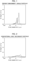
- Fig. 1 is a graph showing an exemplary void distribution (log differential pore volume distribution) curve of the positive electrode active material according to the present embodiment.
- Fig. 2 is a graph showing an exemplary void distribution (log differential pore volume distribution) curve of the positive electrode active material that is constituted with secondary particles of a related art.
- the horizontal axis represents the pore diameter D ( ⁇ m) and the vertical axis represents the log differential pore volume distribution (dV/dlogD).
- dV/dlogD log differential pore volume distribution
- the positive electrode active material layer according to the present embodiment preferably has the average diameter of a void of 0.03 to 0.2 ⁇ m.
- the average diameter of a void in the positive electrode active material layer is within this range, the high output characteristics as described above can be more surely obtained.
- More preferred average diameter of a void is 0.05 to 0.18 ⁇ m.
- the average diameter of a void is obtained from a measurement by mercury intrusion porosimetry according to the same measurement conditions as the measurement of a void fraction described above.
- a ratio of the peak diameter of a void to the average diameter of a void is preferably 1.1 to 2.4.
- the ratio of the peak diameter of a void to the average diameter of a void (peak diameter/average diameter) is within this range, the high output characteristics as described above can be more surely obtained.
- More preferred ratio of the peak diameter of a void to the average diameter of a void (peak diameter/average diameter) is 1.1 to 1.8.
- a positive electrode active material composed of single particles like the present embodiment By using a positive electrode active material composed of single particles like the present embodiment, a small value of the peak diameter/average diameter is yielded, falling within the above range. Due to this reason, a gap between the particles is not excessively reduced and an electrolyte liquid can smear in the whole, and thus high output characteristics are obtained.
- the positive electrode active material layer is formed by, after applying a positive electrode mixture obtained by mixing the positive electrode active material, an electrically conductive aid, a binder, and the like with a solvent onto a collector, a drying and pressurization treatment.
- the electrically conductive aid which can be used include natural graphite, artificial graphite, and acetylene black.
- the binder which can be used include polyvinylidene fluoride, polytetrafluoroethylene, and a polyamide acrylic resin.
- the positive electrode active material according to the present embodiment is constituted by containing compound particles which have a layered structure composed of two or more transition metals, and which have an average particle diameter DSEM of 1 to 7 ⁇ m based on the observation with an electron microscope, a ratio of the 50% particle diameter D50 in a volume-based cumulative particle size distribution to the average particle diameter DSEM (D50/DSEM) of 1 to 4, and a ratio of the 90% particle diameter D90 in the volume-based cumulative particle size distribution to the 10% particle diameter D10 in the volume-based cumulative particle size distribution (D90/D10) of 4 or less.
- the compound particles which have a layered structure composed of two or more transition metals preferably have, as a main component, Ni, Mn, or Al.
- lithium transition metal composite oxide particles having a layered structure and containing Ni are preferably used.
- the composite oxide particles constituting the positive electrode active material are either single particles composed of particles of a single kind or particles composed of only few primary particles. Namely, in the present embodiment, both cases in which the entire particles are single particles or particles constituted with only few primary particles are referred to as "single particles". Furthermore, the positive electrode active material according to the present embodiment preferably has a single particle active material ratio of 80% or higher.
- Fig. 3 is a graph showing the relationship between DSEM and D50/DSEM of the positive electrode active material according to the present embodiment.
- the horizontal axis represents DSEM ( ⁇ m) and the vertical axis represents D50/DSEM.
- the area surrounded by a broken line represents the area of single particles defined by the present embodiment in which DSEM is 1 to 7 ⁇ m and also D50/DSEM is 1 to 4.
- the single particle present within this area has, compared to a secondary particle that is formed by aggregation of primary particles, less particle boundary at which the primary particles are in contact with each other.
- Fig. 4 is an SEM image of the positive electrode active material according to the present embodiment.
- Fig. 5 is an SEM image of the positive electrode active material that is constituted with secondary particles of a related art.
- the single particles constituting the positive electrode active material according to the present embodiment have no aggregation of particles, and thus the entire surface of each particle can be coated by (adhered with) an electrically conductive aid. Due to this reason, the electrically conductive aid can be used at good efficiency, and the output characteristics can be enhanced.
- the secondary particles constituting the positive electrode active material of a related art as they are shown in Fig.
- the secondary particles are formed as a result of aggregation of primary particles so that the electrically conductive aid cannot enter a gap between the primary particles, and thus the entire surface of the primary particle cannot be coated by (adhered with) an electrically conductive aid. Due to this reason, the electrically conductive aid cannot be used at good efficiency, and the output characteristics cannot be enhanced.
- D90/D10 of 4 or less means that, in the volume-based cumulative particle size distribution of composite oxide particles, the distribution width is narrow and the particle size is uniform. As a result of obtaining high durability by having those characteristics, high output characteristics are obtained.
- a three-dimensional particle boundary network as in a positive electrode active material composed of aggregated particles is hardly formed, and a high output design utilizing particle boundary conduction is difficult to achieve, and thus there has been a tendency that the output characteristics are insufficient.
- the improvement can be obtained by decreasing the particle size (DSEM) of single particles.
- the particle size is too small, the interaction between powders increases and the electrode plate filling properties tend to be greatly deteriorated, and, due to a decrease in powder fluidity, the handling property may be greatly deteriorated.
- the particle size at certain level is needed, but, it is considered that an increase in particle size tends to result in a more significant deficiency of output.
- lithium transition metal composite oxide particles according to the present embodiment have more uniform particle size than that of conventional single particles, even in a case in which charge/discharge is carried out at a high current density, variations in charge/discharge depth among particles due to current concentration on some particles can be suppressed, and it is accordingly considered that, while suppressing an increase in resistance due to current concentration, local degradation through the cycle can be suppressed.
- the particles do not collapse even when pressed at a high pressure during the manufacturing of an electrode, and thus it is considered that a uniform void between particles can be obtained.
- the void between particles is filled with an electrolyte to serve as a path for lithium ion diffusion, but, with uniform size of such a path for diffusion, it is considered that variations in amount of charge/discharge among particles can be reduced. Accordingly, it is considered that, even lithium transition metal composite oxide particles having reduced contact particle boundaries between primary particles can achieve good output characteristics while ensuring electrode plate filling properties.
- a heat treatment is needed to be performed under high temperature for growth of particles.
- the Ni element when calcination is performed at a high temperature, the Ni element may be incorporated into the Li site, that is, so-called disorder may occur.
- the disorder inhibits the diffusion of Li ions in composite oxide particles and causes resistance, showing an influence such as a decrease in charge/discharge capacity at a practical current density, a decrease in output characteristics, and the like, and thus it is preferable that such disorder is suppressed. Suppressing the disorder allows achievement of more excellent capacity and output characteristics in single particles.
- the average particle diameter DSEM based on electron microscopic observation is 1 to 7 ⁇ m in view of durability. Furthermore, in view of output density and the electrode plate filling properties, the DSEM is preferably 1.1 ⁇ m or more and more preferably 1.3 ⁇ m or more, and is preferably 4 ⁇ m or less and more preferably 2 ⁇ m or less in a case in which x to be described later is in a range of 0.3 ⁇ x ⁇ 0.6.
- the DSEM is preferably 1.1 ⁇ m or more and more preferably 1.3 ⁇ m or more, and is preferably 5 ⁇ m or less and more preferably 4 ⁇ m or less.
- the average particle diameter DSEM based on electron microscopic observation is determined as follows: a scanning electron microscope (SEM) is used, observation is performed at a magnification of 1000 to 10000 in accordance with the particle diameter, 100 particles having recognizable particle outlines are selected, the equivalent spherical diameters of the selected particles are calculated using an image processing software, and the arithmetic average of the obtained equivalent spherical diameters is determined as DSEM.
- SEM scanning electron microscope
- the composite oxide particle has a ratio D50/DSEM of the 50% particle diameter D50 in a volume-based cumulative particle size distribution to the average particle diameter DSEM based on electron microscopic observation of 1 to 4.
- D50/DSEM 1, it means that all are single particles, and as D50/DSEM is closer to 1, it means that the number of the constituting primary particles is small.
- D50/DSEM is 1 or more but less than 4, and in view of the output density, it is preferably 3 or less, and particularly preferably 2.5 or less.
- the 50% particle diameter D50 of the composite oxide particles is, for example, 1 to 21 ⁇ m, and, in view of the output density, it is preferably 1.5 ⁇ m or more and more preferably 3 ⁇ m or more, and it is preferably 8 ⁇ m or less and more preferably 5.5 ⁇ m or less.
- the 50% particle diameter D50 is obtained as a particle diameter corresponding to a cumulative percentage of 50% from the smaller particle diameter side in the volume-based cumulative particle size distribution that is measured under wet conditions using a laser diffraction particle size distribution analyzer.
- the 90% particle diameter D90 and the 10% particle diameter D10 described below are determined as particle diameters corresponding to cumulative percentages of 90% and 10%, respectively, from the smaller particle diameter side.
- the ratio of the 90% particle diameter D90 to the 10% particle diameter D10 in the volume-based cumulative particle size distribution represents a spread of the particle size distribution, in which smaller ratio indicates more uniform particle diameter of a particle.
- D90/D10 is 4 or less, and in view of the output density, it is preferably 3 or less, and more preferably 2.5 or less.
- the lower limit of D90/D10 is 1.2 or more, for example.
- the lithium transition metal composite oxide has a layered structure having Ni included in the composition.
- Examples of lithium transition metal composite oxide include lithium nickel composite oxide and lithium nickel cobalt manganese composite oxide.
- the lithium transition metal composite oxide preferably has a composition represented by the following formula (1). [Chem.
- the lithium transition metal composite oxide particle may be doped with an element other than the elements forming the lithium transition metal composite oxide.
- an element for doping include B, Na, Mg, Si, P, S, K, Ca, Ti, V, Cr, Zn, Sr, Y, Zr, Nb, Mo, In, Sn, Ba, La, Ce, Nd, Sm, Eu, Gd, Ta, W, and Bi.
- Mg, Ti, and W are preferably exemplified.
- compounds used for doping these elements include oxides and fluorides containing at least one element selected from the group consisting of these elements, and Li composite oxides thereof.
- the amount of doping may be, for example, 0.005% by mol or more and 10% by mol or less with respect to the lithium transition metal composite oxide particles, for example.
- the lithium transition metal composite oxide particles may include core particles containing a lithium transition metal composite oxide and a deposit disposed on the core particle surface.
- the deposit may be disposed on at least a region of a portion of the core particle surface, and is preferably disposed in a region of 1% or more of the surface area of the core particles.
- composition of the deposit is suitably selected in accordance with the purpose and the like, and examples thereof include oxides and fluorides containing at least one kind selected from the group consisting of B, Na, Mg, Si, P, S, K, Ca, Ti, V, Cr, Zn, Sr, Y, Zr, Nb, Mo, In, Sn, Ba, La, Ce, Nd, Sm, Eu, Gd, Ta, W, and Bi, as well as Li composite oxides thereof.
- the content of deposit may be, for example, 0.03% by mass or more and 10% by mass or less, and preferably 0.1% by mass or more and 2% by mass or less in the lithium transition metal composite oxide particles.
- the lithium transition metal composite oxide includes Ni in the composition.
- the disorder of Ni element of the lithium transition metal composite oxide determined by X-ray diffractometry is preferably 4.0% or less, more preferably 2.0% or less, and still more preferably 1.5% or less.
- disorder of Ni element described herein refers to disorder in chemical arrangement (chemical disorder) of a transition metal ion (Ni ion) which is supposed to occupy the original site.
- such a disorder is typically an exchange between lithium ions to occupy the site represented by 3b when expressed in the Wyckoff symbol (3b site, the same applies hereinbelow) and transition metal ions to occupy the 3a site.
- the smaller disorder of Ni element is, the more initial efficiency is improved, and thus is more preferable.
- the disorder of Ni element in a lithium transition metal composite oxide can be determined by X-ray diffractometry.
- the X-ray diffraction spectrum of a lithium transition metal composite oxide is measured by using a CuK ⁇ ray.
- the composition model is represented by Li 1-d Ni d MeO 2 (in which Me is transition metals other than nickel in the lithium transition metal composite oxide), and structure optimization is performed by Rietveld analysis based on the obtained X-ray diffraction spectrum.
- the percentage of d calculated as a result of structure optimization is determined as the disorder value of Ni element.
- the range of a, the ranges of particle diameters represented by DSEM, D50, D90 and D10, and the more preferred range of the disorder of Ni element may vary in accordance with the value of x in the formula (1), and examples thereof will be shown hereinbelow.
- D50/DSEM is 1 or more and 2 or less.
- Lithium transition metal composite oxide particles contained in the positive electrode active material according to the present embodiment can be produced by a method including mixing a lithium compound and an oxide having a desired composition to obtain a raw material mixture, and subjecting the obtained raw material mixture to a heat treatment.
- the heat-treated product obtained after the heat treatment may be subjected to a crushing treatment, and may further be subjected to a treatment for removing unreacted substances, by-products, and the like by washing with water, and the like.
- the product may further be subjected to a dispersion treatment, a classification treatment, and the like.
- Examples of methods of obtaining an oxide having a desired composition include a method in which raw material compounds (hydroxide, carbonate compound, and the like) are mixed according to the intended composition and decomposed into an oxide by a heat treatment, a co-precipitation method in which a raw material compound soluble in a solvent is dissolved in a solvent, then adjustment of the temperature, adjustment of the pH, or addition of a complexing agent, for example, is performed to obtain a precipitate of a precursor in accordance with the intended composition, and the precursors are subjected to a heat treatment to obtain an oxide, and the like.
- a method of producing a positive electrode active material will be described in a case in which the lithium transition metal composite oxide is represented by the formula (1).
- the method of obtaining a raw material mixture includes obtaining a composite oxide containing Ni, Co, and at least one of Mn and Al by a co-precipitation method, and mixing the obtained composite oxide with a lithium compound such as lithium carbonate or lithium hydroxide.
- the method of obtaining a composite oxide by a co-precipitation method may include a seed formation step of adjusting the pH and the like of a mixed aqueous solution containing metal ions in a desired composition to obtain seed crystals, a crystallization step of growing the formed seed crystals to obtain a composite hydroxide having desired characteristics, and a step of subjecting the obtained composite hydroxide to a heat treatment to obtain a composite oxide.
- the details of the method of obtaining a composite oxide may be referred to in Japanese Unexamined Patent Application, Publication No. 2003-292322 , Japanese Unexamined Patent Application, Publication No. 2011-116580 , and the like.
- the composite oxide obtained by a co-precipitation method has a value of D90/D10, which serves as an index of particle size distribution, of 3 or less, for example, preferably 2 or less.
- D50 is 12 ⁇ m or less, for example, preferably 6 ⁇ m or less, and more preferably 4 ⁇ m or less, and is 1 ⁇ m or more, for example, and preferably 2 ⁇ m or more.
- the content ratio Ni/Co/(Mn + Al) of Ni, Co, and Mn and Al in the composite oxide may be 1/1/1, 6/2/2, or 8/1/1, for example.
- the obtained raw material mixture is subjected to a heat treatment, which allows obtainment of lithium transition metal composite oxide particles.
- the temperature for heat treatment is 700°C to 1100°C, for example.
- the heat treatment may be performed at a single temperature, or may also be performed at a plurality of temperatures. In a case in which the heat treatment is performed at a plurality of temperatures, for example, it is possible to perform a first heat treatment at a temperature in a range of 700 to 925°C, and then perform a second heat treatment at a temperature in a range of 930 to 1100°C. Furthermore, a third heat treatment may be additionally performed at a temperature in a range of 700 to 850°C.
- the time of the heat treatment is 1 to 40 hours, for example. In a case in which the heat treatment is performed at a plurality of temperatures, each treatment may be performed for 1 to 10 hours.
- the atmosphere for the heat treatment may be either in air or in an oxygen atmosphere.
- the heat-treated product may be subjected to a crushing treatment, a dispersion treatment, a classification treatment, and the like. As a result, desired lithium transition metal composite oxide particles can be obtained.
- the heat-treated product may be further mixed with a lithium compound to obtain a mixture, followed by an additional heat treatment.
- a lithium compound is further mixed
- the content of lithium in the mixture may be, for example, represented in terms of Li/(Ni + Co + Mn + Al), 1.05 to 1.3, and preferably 1.1 to 1.2.
- the additional heat treatment may be performed at a temperature in a range of 850 to 1000°C, preferably in a range of 870 to 950°C, and it is preferable that the temperature be lower than the temperature of the heat treatment of the raw material mixture.
- the heat treatment time of the additional heat treatment may be, for example, 2 to 15 hours.
- the nonaqueous electrolyte secondary battery according to the present embodiment is provided with the electrode for nonaqueous electrolyte secondary batteries described above as a positive electrode. Furthermore, other than having a conventionally known negative electrode for nonaqueous electrolyte secondary batteries as a negative electrode, the nonaqueous electrolyte secondary battery according to the present embodiment is constituted by including a nonaqueous electrolyte, a separator, or the like.
- nonaqueous electrolyte secondary batteries nonaqueous electrolyte secondary batteries, nonaqueous electrolyte, separator, and the like
- those described in Japanese Unexamined Patent Application, Publication No. 2002-075367 , Japanese Unexamined Patent Application, Publication No. 2011-146390 , Japanese Unexamined Patent Application, Publication No. 2006-12433 , and the like may be suitably used, for example, and the production methods described in those publications can be also used as a method for production.
- the present invention is not limited to the above modes for carrying out the invention, and modifications and improvements within a range in which the object of the present invention is achieved are also encompassed by the present invention.
- the temperature in the tank was maintained at 25°C or higher until the completion of the crystallization step.
- a mixed aqueous solution having a solute content of 1200 mol was prepared and added to the reaction tank over 5 hours or more simultaneously with an aqueous ammonia solution while maintaining the ammonium ion concentration in the solution at 2000 ppm or more so that no additional seed formation would take place in the reaction tank.
- the pH value of the reaction solution was controlled to be maintained at 10.5 to 12.0 with a sodium hydroxide solution. Sampling was successively performed during the reaction, and the addition was completed when D50 of the composite hydroxide particles reached 4.5 ⁇ m or so.
- composition ratio Ni/Co/Mn 0.33/0.33/0.33
- D10 3.4 ⁇ m
- D50 4.5 ⁇ m
- D90 6.0 ⁇ m
- D90/D10 1.8.
- the obtained composite oxide and lithium carbonate were mixed so that Li/(Ni + Co + Mn) becomes 1.15 to obtain a raw material mixture.
- the obtained raw material mixture was calcined in air at 925°C for 7.5 hours and then calcined at 1030°C for 6 hours to obtain a sintered product.
- the obtained sintered product was crushed, subjected to, for 10 minutes, a dispersion treatment in a ball mill made of resin, and then dry-sieved to obtain a powder.
- the obtained powder was classified through a dry classifier into three sizes (large, medium, and small), and medium-sized particles were collected. The proportion of medium-sized particles after classification relative to before classification was 46% by weight.
- the obtained raw material mixture was calcined in air at 925°C for 7.5 hours and then calcined at 1030°C for 6 hours to obtain a sintered product.
- the obtained sintered product was crushed, subjected to, for 30 minutes, a dispersion treatment in a ball mill made of resin, and then dry-sieved to obtain a powder.
- the obtained powder and lithium carbonate were mixed so that Li/(Ni + Co + Mn) becomes 1.17 and calcined in air at 900°C for 10 hours to obtain a sintered product.
- the obtained sintered product was crushed, subjected to, for 30 minutes, a dispersion treatment in a ball mill made of resin, and then dry-sieved to obtain a powder.
- a composite oxide was obtained under the same conditions as in Preparation Example 2.
- the obtained composite oxide and lithium carbonate were mixed so that Li/(Ni + Co + Mn) becomes 1.05 to obtain a raw material mixture.
- the obtained raw material mixture was calcined in air at 925°C for 7.5 hours and then calcined at 1030°C for 6 hours to obtain a sintered product.
- the obtained sintered product was crushed, subjected to, for 30 minutes, a dispersion treatment in a ball mill made of resin, and then dry-sieved to obtain a powder.
- the obtained powder and lithium carbonate were mixed so that Li/(Ni + Co + Mn) becomes 1.17 and calcined in air at 900°C for 10 hours to obtain a sintered product.
- a composite oxide was obtained under the same conditions as in Preparation Example 2.
- the obtained composite oxide and lithium carbonate were mixed so that Li/(Ni + Co + Mn) becomes 1.05 to obtain a raw material mixture.
- the obtained raw material mixture was calcined in air at 925°C for 7.5 hours and then calcined at 1030°C for 6 hours to obtain a sintered product.
- the obtained sintered product was crushed, subjected to, for 10 minutes, a dispersion treatment in a ball mill made of resin, and then dry-sieved to obtain a powder.
- the obtained powder and lithium carbonate were mixed so that Li/(Ni + Co + Mn) becomes 1.14 and calcined in air at 900°C for 10 hours to obtain a sintered product.
- a composite oxide was obtained under the same conditions as in Preparation Example 2.
- the obtained composite oxide and lithium carbonate were mixed so that Li/(Ni + Co + Mn) becomes 1.15 to obtain a raw material mixture.
- the obtained raw material mixture was calcined in air at 950°C for 15 hours to obtain a sintered product.
- the obtained sintered product was crushed, subjected to, for 10 minutes, a dispersion treatment in a ball mill made of resin, and then dry-sieved to obtain a powder.
- the obtained composite oxide and lithium hydroxide monohydrate were mixed so that Li/(Ni + Co + Mn) becomes 1.04 to obtain a raw material mixture.
- the obtained raw material mixture was calcined in an oxygen stream at 780°C for 5 hours, then calcined at 900°C for 10 hours, and further calcined at 780°C for 5 hours to obtain a sintered product.
- the obtained sintered product was crushed and subjected to a dispersion treatment in a ball mill made of resin for 10 minutes to obtain a powder.
- the powder and 10% by mass of water with respect to the powder were added to a high-speed stirring mixer equipped with a rotating blade, and the mixture was stirred at 2000 rpm to elute the residual alkali from the particle boundaries and perform a dispersion treatment, dried at 350°C, and then dry-sieved to obtain a powder.
- each positive electrode active material which has been obtained as described above, 3 parts by mass of acetylene black, and 1 part by mass of polyvinylidene fluoride (PVDF) were dispersed in N-methyl-2-pyrrolidone (NMP) to prepare a positive electrode mixture.
- NMP N-methyl-2-pyrrolidone
- the obtained positive electrode mixture was applied to an aluminum foil that serves as a collector, dried, then compression-molded using a roll press, and cut into a predetermined size, so that a positive electrode was produced.
- Electrodes were attached to each of the positive electrode which has been obtained as described above and graphite as the negative electrode, and then a separator was placed between the positive electrode and the negative electrode, and they were housed in a bag-shaped laminate pack.
- a separator a PE separator with thickness of 16 ⁇ m was used.
- the laminate pack was vacuum-dried at 65°C to remove the moisture adsorbed on each member. After that, in an argon atmosphere, an electrolyte liquid was injected into the laminate pack followed by sealing.
- the battery thus obtained was placed in a thermostat at 25°C and aged under a weak current.
- VC vinylene carbonate
- EMC ethyl methyl carbonate
- DMC dimethyl carbonate
- D10, D50, and D90 of each positive electrode active material were determined by, with use of a laser diffraction particle size distribution analyzer (SALD-3100 manufactured by SHIMADZU CORPORATION), measuring volume-based cumulative particle size distribution, and obtaining each particle diameter corresponding to the cumulative value from the smaller particle diameter side.
- SALD-3100 manufactured by SHIMADZU CORPORATION
- the DSEM of each positive electrode active material was determined as follows; a scanning electron microscope (SEM) was used, and in an image observed at a magnification of 1000 to 10000, one hundred particles having recognizable outlines were selected, and the equivalent spherical diameters of the selected particles were calculated using an image processing software (Image J), and the arithmetic average of the obtained equivalent spherical diameters was determined as DSEM.
- SEM scanning electron microscope
- the value of nickel element disorder was determined by X-ray diffractometry in the following order.
- the X-ray diffraction spectrum of obtained lithium transition metal composite oxide particles was measured by using a CuK ⁇ ray.
- the composition model being expressed as Li 1-d Ni d MeO 2 (in which Me is transition metals other than nickel in the lithium transition metal composite oxide)
- the structure optimization of the lithium transition metal composite oxide was carried out by Rietveld analysis. The percentage of d calculated as a result of structure optimization was determined as the amount of Ni disorder.
- a void fraction By using mercury intrusion porosimetry, a void fraction, a peak diameter of a void, and an average diameter of a void were measured.
- the diameter range having diameter of more than about 5 ⁇ m was assumed as a measurement noise, and thus cut.
- the density was obtained from electrode weight and electrode volume.
- the output density was evaluated for the batteries for evaluation which have been obtained as described above. Specifically, the battery for evaluation was discharged to set it in a 50% SOC state, and then it was maintained under an environment at 25°C for 2 hours. Subsequently, from the 50% SOC state, the battery was discharged at a constant current, the DC resistance after 10 seconds was measured, and the output density was calculated. Furthermore, the lower limit of discharge voltage was set at 2.7 V The results are shown in Table 1.
- Example 1 Positive electrode active material DSEM ( ⁇ m) D10 ( ⁇ m) D50 ( ⁇ m) D90 ( ⁇ m) D50/ DSEM D90/ D10 Amount of Ni disorder (%) Void fraction (%) Peak diameter ( ⁇ m) Average diameter ( ⁇ m) Peak diameter / Average diameter Density (g/cm3) Output density (W/kg)
- Example 1 Preparation Example 3 1.4 1.1 1.9 2.8 1.4 2.5 1.0 39 0.30 0.20 1.5 2.4 3700 Example 2 35 0.25 0.16 1.6 2.7 10220 Example 3 24 0.18 0.14 1.3 3.0 11430 Example 4 19 0.13 0.10 1.3 3.3 11510 Example 5 14 0.09 0.08 1.1 3.6 11380 Example 6 10 0.08 0.06 1.3 3.9 11445
- Example 7 Preparation Example 2 1.2 1.5 3.3 5.1 2.8 3.4 0.9 42 0.28 0.18 1.6 2.4 3800
- Example 8 37 0.24 0.14 1.7 2.7 8090
- Example 9 26 0.20 0.13 1.5 3.0 9630
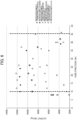
- Fig. 6 is a graph showing the relationship between the void fraction of the positive electrode active material layer of Examples and Comparative Examples and the output.
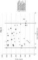
- Fig. 7 is a graph showing the relationship between the density of the positive electrode active material layer of Examples and Comparative Examples and the output.
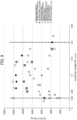
- Fig. 8 is a graph showing the relationship between the peak diameter of a void in a void distribution curve of the positive electrode active material layer of Examples and Comparative Examples and the output.
- Fig. 9 is a graph showing the relationship between the average diameter of a void of the positive electrode active material layer of Examples and Comparative Examples and the output.
- Fig. 10 is a graph showing the relationship between the peak diameter/average diameter of a void of the positive electrode active material of Examples and Comparative Examples and the output.
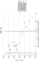
- the horizontal axis represents a peak diameter ( ⁇ m) and the vertical axis represents the output (W/kg). From Fig. 8 , it is confirmed that, as the peak diameter of a void in a void distribution curve is 0.06 to 0.3 ⁇ m, high output characteristics are obtained.
- the horizontal axis represents an average diameter ( ⁇ m) and the vertical axis represents the output (W/kg). From Fig. 9 , it is confirmed that, as the average diameter of a void is 0.03 to 0.2 ⁇ m, high output characteristics are obtained.
- the horizontal axis represents a void peak diameter/void average diameter and the vertical axis represents the output (W/kg). From Fig. 10 , it is confirmed that, as the ratio of a peak diameter of a void to an average diameter of a void (peak diameter/average diameter) is 1.1 to 2.4, high output characteristics are obtained.
- the nonaqueous electrolyte secondary battery provided with the electrode for nonaqueous electrolyte secondary batteries using the positive electrode active material of the present disclosure can be suitably used for large-sized power machines such as electric vehicles.
Landscapes
- Chemical & Material Sciences (AREA)
- Chemical Kinetics & Catalysis (AREA)
- Electrochemistry (AREA)
- General Chemical & Material Sciences (AREA)
- Engineering & Computer Science (AREA)
- Materials Engineering (AREA)
- Inorganic Chemistry (AREA)
- Manufacturing & Machinery (AREA)
- Composite Materials (AREA)
- Battery Electrode And Active Subsutance (AREA)
- Secondary Cells (AREA)
Description
- The present invention relates to an electrode for nonaqueous electrolyte secondary batteries, and a nonaqueous electrolyte secondary battery provided with the same.
- Conventionally, for use in large-sized power machines such as electric vehicles, there has been a demand for a positive electrode active material for nonaqueous electrolyte secondary batteries having high output characteristics. In order to obtain high output characteristics, it is effective to decrease the number of primary particles in secondary particle for constituting the positive electrode active material, or to constitute the positive electrode active material with single particles that are obtained by single dispersion of primary particles.
- However, once cracks are generated in the positive electrode active material due to the pressurization treatment for forming an electrode, expansion and shrinkage upon charge and discharge, or the like, the high output characteristics are not obtained. Due to this reason, various techniques for enhancing the durability of a positive electrode active material have been suggested.
- For example, a nonaqueous secondary battery provided with a positive electrode active material, which has high density like density of 3.5 g/cm3 or more and a void fraction of 25% or less, is suggested (see, Patent Document 1). According to this nonaqueous secondary battery, it is indicated that, by allowing the presence of many voids in a positive electrode, breakage of a collector can be avoided in spite of the high density, and high output characteristics are obtained accordingly.
- Furthermore, a positive electrode for secondary batteries having a void fraction of 30 to 50% and pore diameter of 0.09 to 0.30 µm is suggested, for example (see, Patent Document 2). It is indicated that, according to this positive electrode for secondary batteries, electrode density can be improved by having the void fraction and pore diameter within a suitable range so that the output characteristics can be enhanced.
- Furthermore, a secondary battery provided with a positive electrode active material in which a ratio of the volume of a pore having pore diameter of 0.01 to less than 0.1 µm relative to the volume of a pore having pore diameter of 0.1 to 1.0 µm is 0.3 or less is suggested, for example (see, Patent Document 3). It is indicated that, according to this secondary battery, the output characteristics can be enhanced by having suitable pore distribution.
- Patent Document 1:
Japanese Unexamined Patent Application, Publication No. 2009-48876 - Patent Document 2:
Japanese Unexamined Patent Application, Publication No. 2010-15904 - Patent Document 3:
Japanese Unexamined Patent Application, Publication No. 2012-209161 - However, the techniques of
Patent Documents 1 to 3 all use secondary particles, and, in actual cases, the secondary particles constituting the positive electrode active material are collapsed during press molding of a positive electrode or the like, and also, as a result of having high resistance due to reduced void diameter, the high output characteristics are not obtained. In particular, once cracks are generated in a positive electrode active material, the electrolyte liquid on a freshly formed surface is decomposed by oxidation, and, as a result of forming a thick SEI, the high output characteristics are not obtained. - The present invention is achieved in view of the problems that are described above, and object of the present invention is to provide an electrode for nonaqueous electrolyte secondary batteries from which high output characteristics can be obtained, and a nonaqueous electrolyte secondary battery provided with the electrode.
- To achieve the object described above, the present invention provides an electrode for nonaqueous electrolyte secondary batteries including a collector and a positive electrode active material layer that is arranged on the collector and contains a positive electrode active material, in which the positive electrode active material is configured to contain compound particles which have a layered structure composed of two or more transition metals, and which have an average particle diameter DSEM of 1 to 7 µm based on the observation with an electron microscope, a ratio of the 50% particle diameter D50 in a volume-based cumulative particle size distribution to the average particle diameter DSEM (D50/DSEM) of 1 to 4, and a ratio of the 90% particle diameter D90 in the volume-based cumulative particle size distribution to the 10% particle diameter D10 in the volume-based cumulative particle size distribution (D90/D10) of 4 or less, and the positive electrode active material layer has a void fraction of 10 to 45%.
- The positive electrode active material layer according to the invention has density of 2.7 to 3.9 g/cm3.
- Accordingly, even higher output characteristics are obtained. When a secondary particle is pressed, cracks are generated so that a portion not applied with an aid becomes a surface, but, in the case of a single particle, cracks are not generated from the beginning, and thus the output characteristics are relatively high.
- With regard to the positive electrode active material layer, a peak diameter of a void in a void distribution curve is preferably 0.06 to 0.3 µm.
- With regard to the positive electrode active material layer, an average diameter of the void is preferably 0.03 to 0.2 µm.
- With regard to the positive electrode active material layer, a ratio of the peak diameter of the void to the average diameter of the void (peak diameter/average diameter) is preferably 1.1 to 2.4.
- The positive electrode active material preferably has Ni, Mn, or Al as a main component.
- A nonaqueous electrolyte secondary battery including the electrode for nonaqueous electrolyte secondary batteries is provided.
- According to the present invention, an electrode for nonaqueous electrolyte secondary batteries which enables obtainment of output characteristics that are higher than before, and a nonaqueous electrolyte secondary battery provided with the electrode can be provided.
-
-
Fig. 1 is a graph showing an exemplary void distribution curve of a positive electrode active material according to the present embodiment. -
Fig. 2 is a graph showing an exemplary void distribution curve of a positive electrode active material that is constituted with secondary particles of a related art. -
Fig. 3 is a graph showing the relationship between DSEM and D50/DSEM of the positive electrode active material according to the present embodiment. -
Fig. 4 is an SEM image of the positive electrode active material according to the present embodiment. -
Fig. 5 is an SEM image of the positive electrode active material that is constituted with the secondary particles of a related art. -
Fig. 6 is a graph showing the relationship between a void fraction of a positive electrode active material layer of Examples and Comparative Examples and an output. -
Fig. 7 is a graph showing the relationship between density of the positive electrode active material layer of Examples and Comparative Examples and the output. -
Fig. 8 is a graph showing the relationship between a peak diameter of a void in a void distribution curve of the positive electrode active material layer of Examples and Comparative Examples and the output. -
Fig. 9 is a graph showing the relationship between an average diameter of the void of the positive electrode active material layer of Examples and Comparative Examples and the output. -
Fig. 10 is a graph showing the relationship between a peak diameter/average diameter of the void of the positive electrode active material of Examples and Comparative Examples and the output. - One embodiment of the present invention is described in detail in view of the drawings. However, the present invention is not limited to the following embodiments. Furthermore, in the present specification, the content of each component means, in a case in which a plurality of substances corresponding to each component are present in the composition, the total amount of the plurality of substances present in the composition unless specifically described otherwise.
- The electrode for nonaqueous electrolyte secondary batteries according to the present embodiment is provided with a collector and an electrode active material layer that is arranged on the collector and contains an active material. The electrode for nonaqueous electrolyte secondary batteries according to the present embodiment is preferably used as a positive electrode of a nonaqueous electrolyte secondary battery, and it is particularly preferably used as a positive electrode of a lithium ion secondary battery. Due to this reason, a positive electrode for nonaqueous electrolyte secondary batteries in which the electrode for nonaqueous electrolyte secondary batteries according to the present embodiment is used as a positive electrode of a lithium ion secondary battery is described in detail hereinbelow.
- The positive electrode for nonaqueous electrolyte secondary batteries according to the present embodiment is provided with a collector and a positive electrode active material layer that is arranged on the collector and contains a positive electrode active material. As for the collector, aluminum, nickel, stainless steel, or the like can be used, for example. The positive electrode active material layer is constituted by containing, other than the positive electrode active material, an electrically conductive aid, a binder, and the like.
- The positive electrode active material layer according to the present embodiment has a void fraction of 10 to 45%. As it is described below, because the positive electrode active material layer according to the present embodiment is constituted with a positive electrode active material composed of single particles, a route (path) for having the diffusion of lithium ions is maintained at sufficient level and also, even when the void fraction is reduced to a range of 10 to 45% according to high-densification of the positive electrode active material layer to have even higher output characteristics, cracks are not generated in the positive electrode active material layer. Namely, because a portion not coated (adhered) with an electrically conductive aid does not newly become a surface (yield a new surface) due to an occurrence of cracks resulting from high-densification like the positive electrode active materials composed of secondary particles of a related art and also the constitution according to the present embodiment includes single particles of which surfaces are entirely coated with an electrically conductive aid, high output characteristics are obtained. More preferred void fraction is 20 to 35%.
- Herein, the void fraction according to the present embodiment can be measured by a mercury intrusion porosimetry. Furthermore, the void fraction can be adjusted by adjusting the particle diameter of a positive electrode active material or adjusting the pressurizing conditions in the method for producing a positive electrode active material layer which is described later.
- The positive electrode active material layer according to the present embodiment preferably has density of 2.7 to 3.9 g/cm3. As it is described above, since the positive electrode active material layer according to the present embodiment is constituted with a positive electrode active material which is composed of single particles, even when high-densification of the positive electrode active material layer is carried out within a range of 2.7 to 3.9 g/cm3 to have high output characteristics, cracks are not generated in the positive electrode active material layer as the void fraction is limited within a range of 10 to 45%. Namely, because a portion not coated (adhered) with an electrically conductive aid does not newly become a surface (yield a new surface) due to an occurrence of cracks resulting from high-densification like the positive electrode active materials composed of secondary particles of a related art and also the constitution according to the present embodiment includes single particles of which surfaces are entirely coated with an electrically conductive aid, high output characteristics are obtained. More preferred density is 3.0 to 3.6 g/cm3.
- Herein, the density according to the present embodiment can be measured by a device for measuring density. Furthermore, the density can be adjusted by adjusting the particle diameter of a positive electrode active material or adjusting the pressurizing conditions in the method for producing a positive electrode active material layer which is described later.
- With regard to the positive electrode active material layer according to the present embodiment, the peak diameter of a void in a void distribution curve (pore distribution curve) is preferably 0.06 to 0.3 µm. As the peak diameter of a void in a positive electrode active material layer is within this range, the high output characteristics as described above can be more surely obtained. More preferred peak diameter of a void is 0.12 to 0.25 µm.
- The peak diameter of a void according to the present embodiment means the diameter D of a pore which is the highest in a void distribution curve obtained from a measurement by mercury intrusion porosimetry like the measurement of the void fraction described above, in greater detail, the highest in a log differential pore volume distribution (dV/dlogD). The log differential pore volume distribution (dV/dlogD) indicates a plot that is obtained by plotting, with respect to the average pore diameter, a value obtained by dividing the differential pore volume dV by log differential value dlogD of pore diameter.
- Herein,
Fig. 1 is a graph showing an exemplary void distribution (log differential pore volume distribution) curve of the positive electrode active material according to the present embodiment. Furthermore,Fig. 2 is a graph showing an exemplary void distribution (log differential pore volume distribution) curve of the positive electrode active material that is constituted with secondary particles of a related art. In thoseFig. 1 and Fig. 2 , the horizontal axis represents the pore diameter D (µm) and the vertical axis represents the log differential pore volume distribution (dV/dlogD). In any of those graphs, three examples are shown with a solid line, a broken line, and a one-dotted chain line, respectively. As it is evident from those figures, it is recognized that a sharp peak is confirmed from the present embodiment in which a positive electrode active material composed of single particles is used, while a broad peak is confirmed from a conventional case in which a positive electrode active material composed of secondary particles is used. - The positive electrode active material layer according to the present embodiment preferably has the average diameter of a void of 0.03 to 0.2 µm. As the average diameter of a void in the positive electrode active material layer is within this range, the high output characteristics as described above can be more surely obtained. More preferred average diameter of a void is 0.05 to 0.18 µm. Furthermore, the average diameter of a void is obtained from a measurement by mercury intrusion porosimetry according to the same measurement conditions as the measurement of a void fraction described above.
- Furthermore, with regard to the positive electrode active material layer according to the present embodiment, a ratio of the peak diameter of a void to the average diameter of a void (peak diameter/average diameter) is preferably 1.1 to 2.4. As the ratio of the peak diameter of a void to the average diameter of a void (peak diameter/average diameter) is within this range, the high output characteristics as described above can be more surely obtained. More preferred ratio of the peak diameter of a void to the average diameter of a void (peak diameter/average diameter) is 1.1 to 1.8.
- By using a positive electrode active material composed of single particles like the present embodiment, a small value of the peak diameter/average diameter is yielded, falling within the above range. Due to this reason, a gap between the particles is not excessively reduced and an electrolyte liquid can smear in the whole, and thus high output characteristics are obtained.
- The positive electrode active material layer is formed by, after applying a positive electrode mixture obtained by mixing the positive electrode active material, an electrically conductive aid, a binder, and the like with a solvent onto a collector, a drying and pressurization treatment. Examples of the electrically conductive aid which can be used include natural graphite, artificial graphite, and acetylene black. Examples of the binder which can be used include polyvinylidene fluoride, polytetrafluoroethylene, and a polyamide acrylic resin.
- Next, the positive electrode active material is described in detail. The positive electrode active material according to the present embodiment is constituted by containing compound particles which have a layered structure composed of two or more transition metals, and which have an average particle diameter DSEM of 1 to 7 µm based on the observation with an electron microscope, a ratio of the 50% particle diameter D50 in a volume-based cumulative particle size distribution to the average particle diameter DSEM (D50/DSEM) of 1 to 4, and a ratio of the 90% particle diameter D90 in the volume-based cumulative particle size distribution to the 10% particle diameter D10 in the volume-based cumulative particle size distribution (D90/D10) of 4 or less.
- The compound particles which have a layered structure composed of two or more transition metals preferably have, as a main component, Ni, Mn, or Al. Among them, lithium transition metal composite oxide particles having a layered structure and containing Ni (hereinbelow, also described as "composite oxide particles" ) are preferably used.
- DSEM of 1 to 7 µm and also D50/DSEM of 1 to 4 means that the composite oxide particles constituting the positive electrode active material are either single particles composed of particles of a single kind or particles composed of only few primary particles. Namely, in the present embodiment, both cases in which the entire particles are single particles or particles constituted with only few primary particles are referred to as "single particles". Furthermore, the positive electrode active material according to the present embodiment preferably has a single particle active material ratio of 80% or higher.
- Herein,
Fig. 3 is a graph showing the relationship between DSEM and D50/DSEM of the positive electrode active material according to the present embodiment. InFig. 3 , the horizontal axis represents DSEM (µm) and the vertical axis represents D50/DSEM. InFig. 3 , the area surrounded by a broken line represents the area of single particles defined by the present embodiment in which DSEM is 1 to 7 µm and also D50/DSEM is 1 to 4. The single particle present within this area has, compared to a secondary particle that is formed by aggregation of primary particles, less particle boundary at which the primary particles are in contact with each other. -
Fig. 4 is an SEM image of the positive electrode active material according to the present embodiment.Fig. 5 is an SEM image of the positive electrode active material that is constituted with secondary particles of a related art. As it is shown inFig. 4 , the single particles constituting the positive electrode active material according to the present embodiment have no aggregation of particles, and thus the entire surface of each particle can be coated by (adhered with) an electrically conductive aid. Due to this reason, the electrically conductive aid can be used at good efficiency, and the output characteristics can be enhanced. On the other hand, with regard to the secondary particles constituting the positive electrode active material of a related art as they are shown inFig. 5 , the secondary particles are formed as a result of aggregation of primary particles so that the electrically conductive aid cannot enter a gap between the primary particles, and thus the entire surface of the primary particle cannot be coated by (adhered with) an electrically conductive aid. Due to this reason, the electrically conductive aid cannot be used at good efficiency, and the output characteristics cannot be enhanced. - Furthermore, D90/D10 of 4 or less means that, in the volume-based cumulative particle size distribution of composite oxide particles, the distribution width is narrow and the particle size is uniform. As a result of obtaining high durability by having those characteristics, high output characteristics are obtained.
- Herein, as compared with a positive electrode active material containing lithium transition metal composite oxide particles composed of secondary particles in which primary particles are aggregated in a large number, in a conventional positive electrode active material containing lithium transition metal composite oxide particles composed of single particles, a decrease in capacity retention ratio due to the disconnection of the electrical conduction path of lithium ions caused by the particle boundary dissociation of secondary particles during a charge/discharge cycle is suppressed, and also an increase in the diffusion/migration resistance of lithium ions is suppressed, and thus excellent durability is exhibited. Meanwhile, a three-dimensional particle boundary network as in a positive electrode active material composed of aggregated particles is hardly formed, and a high output design utilizing particle boundary conduction is difficult to achieve, and thus there has been a tendency that the output characteristics are insufficient. It is considered that, to have high output characteristics, the improvement can be obtained by decreasing the particle size (DSEM) of single particles. However, in a case in which the particle size is too small, the interaction between powders increases and the electrode plate filling properties tend to be greatly deteriorated, and, due to a decrease in powder fluidity, the handling property may be greatly deteriorated. Meanwhile, in particular, for obtaining a practical energy density, the particle size at certain level is needed, but, it is considered that an increase in particle size tends to result in a more significant deficiency of output.
- As the lithium transition metal composite oxide particles according to the present embodiment have more uniform particle size than that of conventional single particles, even in a case in which charge/discharge is carried out at a high current density, variations in charge/discharge depth among particles due to current concentration on some particles can be suppressed, and it is accordingly considered that, while suppressing an increase in resistance due to current concentration, local degradation through the cycle can be suppressed.
- Furthermore, with uniform particle size of lithium transition metal composite oxide particles having reduced particle boundaries, the particles do not collapse even when pressed at a high pressure during the manufacturing of an electrode, and thus it is considered that a uniform void between particles can be obtained. In addition, in a case in which a battery is formed, the void between particles is filled with an electrolyte to serve as a path for lithium ion diffusion, but, with uniform size of such a path for diffusion, it is considered that variations in amount of charge/discharge among particles can be reduced. Accordingly, it is considered that, even lithium transition metal composite oxide particles having reduced contact particle boundaries between primary particles can achieve good output characteristics while ensuring electrode plate filling properties.
- Furthermore, generally, in a case in which single particles are synthesized, a heat treatment is needed to be performed under high temperature for growth of particles. In particular, in a composition having a high Ni proportion, when calcination is performed at a high temperature, the Ni element may be incorporated into the Li site, that is, so-called disorder may occur. The disorder inhibits the diffusion of Li ions in composite oxide particles and causes resistance, showing an influence such as a decrease in charge/discharge capacity at a practical current density, a decrease in output characteristics, and the like, and thus it is preferable that such disorder is suppressed. Suppressing the disorder allows achievement of more excellent capacity and output characteristics in single particles.
- In the composite oxide particles constituting the positive electrode active material, the average particle diameter DSEM based on electron microscopic observation is 1 to 7 µm in view of durability. Furthermore, in view of output density and the electrode plate filling properties, the DSEM is preferably 1.1 µm or more and more preferably 1.3 µm or more, and is preferably 4 µm or less and more preferably 2 µm or less in a case in which x to be described later is in a range of 0.3 ≤ x < 0.6. Furthermore, in a case in which x is in a range of 0.6 ≤ x ≤ 0.95, the DSEM is preferably 1.1 µm or more and more preferably 1.3 µm or more, and is preferably 5 µm or less and more preferably 4 µm or less.
- The average particle diameter DSEM based on electron microscopic observation is determined as follows: a scanning electron microscope (SEM) is used, observation is performed at a magnification of 1000 to 10000 in accordance with the particle diameter, 100 particles having recognizable particle outlines are selected, the equivalent spherical diameters of the selected particles are calculated using an image processing software, and the arithmetic average of the obtained equivalent spherical diameters is determined as DSEM.
- The composite oxide particle has a ratio D50/DSEM of the 50% particle diameter D50 in a volume-based cumulative particle size distribution to the average particle diameter DSEM based on electron microscopic observation of 1 to 4. In a case in which D50/DSEM is 1, it means that all are single particles, and as D50/DSEM is closer to 1, it means that the number of the constituting primary particles is small. In view of the durability, it is preferable that D50/DSEM is 1 or more but less than 4, and in view of the output density, it is preferably 3 or less, and particularly preferably 2.5 or less.
- Furthermore, the 50% particle diameter D50 of the composite oxide particles is, for example, 1 to 21 µm, and, in view of the output density, it is preferably 1.5 µm or more and more preferably 3 µm or more, and it is preferably 8 µm or less and more preferably 5.5 µm or less.
- The 50% particle diameter D50 is obtained as a particle diameter corresponding to a cumulative percentage of 50% from the smaller particle diameter side in the volume-based cumulative particle size distribution that is measured under wet conditions using a laser diffraction particle size distribution analyzer. Similarly, the 90% particle diameter D90 and the 10% particle diameter D10 described below are determined as particle diameters corresponding to cumulative percentages of 90% and 10%, respectively, from the smaller particle diameter side.
- With regard to the composite oxide particle, the ratio of the 90% particle diameter D90 to the 10% particle diameter D10 in the volume-based cumulative particle size distribution represents a spread of the particle size distribution, in which smaller ratio indicates more uniform particle diameter of a particle. D90/D10 is 4 or less, and in view of the output density, it is preferably 3 or less, and more preferably 2.5 or less. The lower limit of D90/D10 is 1.2 or more, for example.
- The lithium transition metal composite oxide has a layered structure having Ni included in the composition. Examples of lithium transition metal composite oxide include lithium nickel composite oxide and lithium nickel cobalt manganese composite oxide. Among them, the lithium transition metal composite oxide preferably has a composition represented by the following formula (1).
[Chem. 1] LipNixCoyM1 zO2 + α ···
Formula (1)
[in the formula (1), p, x, y, z, and α satisfy 1.0 ≤ p ≤ 1.3, 0.3 ≤ x ≤ 0.95, 0 ≤ y ≤ 0.4, 0 ≤ z ≤ 0.5, x + y + z = 1, and -0.1 ≤ α ≤ 0.1, and M1 represents at least one of Mn and Al]. - The lithium transition metal composite oxide particle may be doped with an element other than the elements forming the lithium transition metal composite oxide. Examples of an element for doping include B, Na, Mg, Si, P, S, K, Ca, Ti, V, Cr, Zn, Sr, Y, Zr, Nb, Mo, In, Sn, Ba, La, Ce, Nd, Sm, Eu, Gd, Ta, W, and Bi. Among them, Mg, Ti, and W are preferably exemplified. Examples of compounds used for doping these elements include oxides and fluorides containing at least one element selected from the group consisting of these elements, and Li composite oxides thereof. The amount of doping may be, for example, 0.005% by mol or more and 10% by mol or less with respect to the lithium transition metal composite oxide particles, for example.
- Furthermore, the lithium transition metal composite oxide particles may include core particles containing a lithium transition metal composite oxide and a deposit disposed on the core particle surface. The deposit may be disposed on at least a region of a portion of the core particle surface, and is preferably disposed in a region of 1% or more of the surface area of the core particles. The composition of the deposit is suitably selected in accordance with the purpose and the like, and examples thereof include oxides and fluorides containing at least one kind selected from the group consisting of B, Na, Mg, Si, P, S, K, Ca, Ti, V, Cr, Zn, Sr, Y, Zr, Nb, Mo, In, Sn, Ba, La, Ce, Nd, Sm, Eu, Gd, Ta, W, and Bi, as well as Li composite oxides thereof. The content of deposit may be, for example, 0.03% by mass or more and 10% by mass or less, and preferably 0.1% by mass or more and 2% by mass or less in the lithium transition metal composite oxide particles.
- The lithium transition metal composite oxide includes Ni in the composition. In view of the initial efficiency in a nonaqueous electrolyte secondary battery, the disorder of Ni element of the lithium transition metal composite oxide determined by X-ray diffractometry is preferably 4.0% or less, more preferably 2.0% or less, and still more preferably 1.5% or less. The expression "disorder of Ni element" described herein refers to disorder in chemical arrangement (chemical disorder) of a transition metal ion (Ni ion) which is supposed to occupy the original site. In a lithium transition metal composite oxide having a layered structure, such a disorder is typically an exchange between lithium ions to occupy the site represented by 3b when expressed in the Wyckoff symbol (3b site, the same applies hereinbelow) and transition metal ions to occupy the 3a site. The smaller disorder of Ni element is, the more initial efficiency is improved, and thus is more preferable.
- The disorder of Ni element in a lithium transition metal composite oxide can be determined by X-ray diffractometry. The X-ray diffraction spectrum of a lithium transition metal composite oxide is measured by using a CuKα ray. The composition model is represented by Li1-dNidMeO2 (in which Me is transition metals other than nickel in the lithium transition metal composite oxide), and structure optimization is performed by Rietveld analysis based on the obtained X-ray diffraction spectrum. The percentage of d calculated as a result of structure optimization is determined as the disorder value of Ni element.
- In a case in which the lithium transition metal composite oxide has a composition represented by the formula (1), in one embodiment of the present invention, the range of a, the ranges of particle diameters represented by DSEM, D50, D90 and D10, and the more preferred range of the disorder of Ni element may vary in accordance with the value of x in the formula (1), and examples thereof will be shown hereinbelow.
- In the formula (1), in a case in which x satisfies 0.3 ≤ x < 0.8, in view of the output density, it is preferable that D50/DSEM is 1 or more and 2 or less.
- In the formula (1), in a case in which x satisfies 0.3 ≤ x < 0.6, in view of the output density, it is preferable that at least one of the embodiments shown below is satisfied.
- (i) In view of charge/discharge capacity, it is preferable that the disorder of Ni element in the lithium transition metal composite oxide particles determined by X-ray diffractometry is 1.5% or less.
- (ii) It is preferable that D90/D10 is 3.0 or less, and more preferably 2.5 or less.
- (iii) In view of electrode plate filling properties, it is preferable that D50 is 1 µm or more and 5.5 µm or less, and more preferably 1 µm or more and 3 µm or less.
- (iv) It is preferable that a in the formula (1) satisfies 1.1 < a < 1.2.
- In the formula (1), in a case in which x satisfies 0.6 ≤ x < 0.8, in view of the output density, it is preferable that at least one of the embodiments shown below is satisfied.
- (i) In view of charge/discharge capacity, it is preferable that the disorder of Ni element in the lithium transition metal composite oxide particles determined by X-ray diffractometry is 2.0% or less.
- (ii) It is preferable that D90/D10 is 2.3 or less.
- (iii) In view of electrode plate filling properties, it is preferable that D50 is 1 µm or more and 5.5 µm or less.
- In the formula (1), in a case in which x satisfies 0.8 ≤ x < 0.95, in view of the output density, it is preferable that at least one of the embodiments shown below is satisfied.
- (i) In view of charge/discharge capacity, it is preferable that the disorder of Ni element in the lithium transition metal composite oxide particles determined by X-ray diffractometry is 4.0% or less.
- (ii) It is preferable that D90/D10 is 3.0 or less.
- (iii) In view of electrode plate filling properties, it is preferable that D50 is 1 µm or more and 5.5 µm or less.
- Lithium transition metal composite oxide particles contained in the positive electrode active material according to the present embodiment can be produced by a method including mixing a lithium compound and an oxide having a desired composition to obtain a raw material mixture, and subjecting the obtained raw material mixture to a heat treatment. The heat-treated product obtained after the heat treatment may be subjected to a crushing treatment, and may further be subjected to a treatment for removing unreacted substances, by-products, and the like by washing with water, and the like. Furthermore, the product may further be subjected to a dispersion treatment, a classification treatment, and the like.
- Examples of methods of obtaining an oxide having a desired composition include a method in which raw material compounds (hydroxide, carbonate compound, and the like) are mixed according to the intended composition and decomposed into an oxide by a heat treatment, a co-precipitation method in which a raw material compound soluble in a solvent is dissolved in a solvent, then adjustment of the temperature, adjustment of the pH, or addition of a complexing agent, for example, is performed to obtain a precipitate of a precursor in accordance with the intended composition, and the precursors are subjected to a heat treatment to obtain an oxide, and the like. Hereinbelow, one example of a method of producing a positive electrode active material will be described in a case in which the lithium transition metal composite oxide is represented by the formula (1).
- It is preferable that the method of obtaining a raw material mixture includes obtaining a composite oxide containing Ni, Co, and at least one of Mn and Al by a co-precipitation method, and mixing the obtained composite oxide with a lithium compound such as lithium carbonate or lithium hydroxide.
- The method of obtaining a composite oxide by a co-precipitation method may include a seed formation step of adjusting the pH and the like of a mixed aqueous solution containing metal ions in a desired composition to obtain seed crystals, a crystallization step of growing the formed seed crystals to obtain a composite hydroxide having desired characteristics, and a step of subjecting the obtained composite hydroxide to a heat treatment to obtain a composite oxide. The details of the method of obtaining a composite oxide may be referred to in
Japanese Unexamined Patent Application, Publication No. 2003-292322 Japanese Unexamined Patent Application, Publication No. 2011-116580 - The composite oxide obtained by a co-precipitation method has a value of D90/D10, which serves as an index of particle size distribution, of 3 or less, for example, preferably 2 or less. In addition, D50 is 12 µm or less, for example, preferably 6 µm or less, and more preferably 4 µm or less, and is 1 µm or more, for example, and preferably 2 µm or more.
- The content ratio Ni/Co/(Mn + Al) of Ni, Co, and Mn and Al in the composite oxide may be 1/1/1, 6/2/2, or 8/1/1, for example.
- It is preferable that the raw material mixture contains a lithium compound in addition to the composite oxide. Examples of lithium compounds include lithium carbonate, lithium hydroxide, and lithium oxide. The particle diameter of the lithium compound to be used is, as D50, 0.1 to 100 µm, for example, and preferably 2 to 20 µm. The content of lithium with respect to the raw material mixture may be, in terms of Li/(Ni + Co + Mn + Al), 1.0 or more and 1.3 or less, for example, and preferably 1.2 or less. The composite oxide and the lithium compound may be mixed by using a high-speed shear mixer or the like, for example.
- The obtained raw material mixture is subjected to a heat treatment, which allows obtainment of lithium transition metal composite oxide particles. The temperature for heat treatment is 700°C to 1100°C, for example. The heat treatment may be performed at a single temperature, or may also be performed at a plurality of temperatures. In a case in which the heat treatment is performed at a plurality of temperatures, for example, it is possible to perform a first heat treatment at a temperature in a range of 700 to 925°C, and then perform a second heat treatment at a temperature in a range of 930 to 1100°C. Furthermore, a third heat treatment may be additionally performed at a temperature in a range of 700 to 850°C.
- The time of the heat treatment is 1 to 40 hours, for example. In a case in which the heat treatment is performed at a plurality of temperatures, each treatment may be performed for 1 to 10 hours. The atmosphere for the heat treatment may be either in air or in an oxygen atmosphere.
- The heat-treated product may be subjected to a crushing treatment, a dispersion treatment, a classification treatment, and the like. As a result, desired lithium transition metal composite oxide particles can be obtained.
- In addition, after being subjected to a crushing treatment, a dispersion treatment, a classification treatment, or the like, the heat-treated product may be further mixed with a lithium compound to obtain a mixture, followed by an additional heat treatment. In a case in which a lithium compound is further mixed, the content of lithium in the mixture may be, for example, represented in terms of Li/(Ni + Co + Mn + Al), 1.05 to 1.3, and preferably 1.1 to 1.2. In addition, the additional heat treatment may be performed at a temperature in a range of 850 to 1000°C, preferably in a range of 870 to 950°C, and it is preferable that the temperature be lower than the temperature of the heat treatment of the raw material mixture. The heat treatment time of the additional heat treatment may be, for example, 2 to 15 hours. After the additional heat treatment, a crushing treatment, a dispersion treatment, a classification treatment, or the like may be performed.
- The nonaqueous electrolyte secondary battery according to the present embodiment is provided with the electrode for nonaqueous electrolyte secondary batteries described above as a positive electrode. Furthermore, other than having a conventionally known negative electrode for nonaqueous electrolyte secondary batteries as a negative electrode, the nonaqueous electrolyte secondary battery according to the present embodiment is constituted by including a nonaqueous electrolyte, a separator, or the like.
- As the negative electrode for nonaqueous electrolyte secondary batteries, nonaqueous electrolyte, separator, and the like, those described in
Japanese Unexamined Patent Application, Publication No. 2002-075367 Japanese Unexamined Patent Application, Publication No. 2011-146390 Japanese Unexamined Patent Application, Publication No. 2006-12433 - Furthermore, the present invention is not limited to the above modes for carrying out the invention, and modifications and improvements within a range in which the object of the present invention is achieved are also encompassed by the present invention.
- Next, Examples of the present invention are described. However, the present invention is not limited to the following Examples.
- First, 10 kg of water was charged in a reaction tank, and, under stirring, the ammonium ion concentration was adjusted to 1.8% by mass. The temperature in the tank was set at 25°C, and a nitrogen gas was circulated in the tank to maintain the oxygen concentration of the inner space of the reaction tank at 10% by volume or less. A 25% by mass aqueous sodium hydroxide solution was added to water in the reaction tank, and the pH value of the solution in the tank was adjusted to 13.5 or higher. Next, a nickel sulfate solution, a cobalt sulfate solution, and a manganese sulfate solution were mixed to prepare a mixed aqueous solution having a molar ratio of 1 : 1 : 1. The mixed aqueous solution was added until the solute content reached 4 mol, and, while controlling the pH value of the reaction solution at 12.0 or higher with a sodium hydroxide solution, seed formation was carried out.
- After the seed forming step, the temperature in the tank was maintained at 25°C or higher until the completion of the crystallization step. In addition, a mixed aqueous solution having a solute content of 1200 mol was prepared and added to the reaction tank over 5 hours or more simultaneously with an aqueous ammonia solution while maintaining the ammonium ion concentration in the solution at 2000 ppm or more so that no additional seed formation would take place in the reaction tank. During the reaction, the pH value of the reaction solution was controlled to be maintained at 10.5 to 12.0 with a sodium hydroxide solution. Sampling was successively performed during the reaction, and the addition was completed when D50 of the composite hydroxide particles reached 4.5 µm or so. Next, the product was washed with water, filtered, and dried, so that composite hydroxide particles were obtained. The obtained hydroxide precursor was subjected to a heat treatment at 300°C for 20 hours in the ambient atmosphere, thereby obtaining a composite oxide having the following properties: composition ratio Ni/Co/Mn = 0.33/0.33/0.33, D10 = 3.4 µm, D50 = 4.5 µm, D90 = 6.0 µm, and D90/D10 = 1.8.
- The obtained composite oxide and lithium carbonate were mixed so that Li/(Ni + Co + Mn) becomes 1.15 to obtain a raw material mixture. The obtained raw material mixture was calcined in air at 925°C for 7.5 hours and then calcined at 1030°C for 6 hours to obtain a sintered product. The obtained sintered product was crushed, subjected to, for 10 minutes, a dispersion treatment in a ball mill made of resin, and then dry-sieved to obtain a powder. The obtained powder was classified through a dry classifier into three sizes (large, medium, and small), and medium-sized particles were collected. The proportion of medium-sized particles after classification relative to before classification was 46% by weight. According to the above, lithium transition metal composite oxide particles represented by the composition formula of Li1.15Ni0.33Co0.33Mn0.33O2 and having the following properties were obtained: average particle diameter DSEM based on electron microscopic observation is 3.6 µm, D10 = 3.7 µm, D50 = 5.1 µm, D90 = 6.7 µm, ratio D50/DSEM of D50 to average particle diameter DSEM is 1.4, ratio D90/D10 in particle size distribution is 1.8, and amount of Ni disorder is 0.3%.
- Under the same conditions as in Preparation Example 1 except that the timing of the completion of addition of a mixed aqueous solution in the crystallization step was changed to the time at which the value of D50 of composite hydroxide particles reached about 3.0 µm, a composite oxide having the following properties was obtained: composition ratio Ni/Co/Mn = 0.33/0.33/0.33, D10 = 2.2 µm, D50 = 3.0 µm, D90 = 4.1 µm, and D90/D10 = 1.9. The obtained composite oxide and lithium carbonate were mixed so that Li/(Ni + Co + Mn) becomes 1.05 to obtain a raw material mixture. The obtained raw material mixture was calcined in air at 925°C for 7.5 hours and then calcined at 1030°C for 6 hours to obtain a sintered product. The obtained sintered product was crushed, subjected to, for 30 minutes, a dispersion treatment in a ball mill made of resin, and then dry-sieved to obtain a powder. The obtained powder and lithium carbonate were mixed so that Li/(Ni + Co + Mn) becomes 1.17 and calcined in air at 900°C for 10 hours to obtain a sintered product. The obtained sintered product was crushed, subjected to, for 30 minutes, a dispersion treatment in a ball mill made of resin, and then dry-sieved to obtain a powder. According to the above, lithium transition metal composite oxide particles represented by the composition formula of Li1.17Ni0.33Co0.33Mn0.33O2 and having the following properties were obtained: average particle diameter DSEM is 1.2 µm, D10 = 1.5 µm, D50 = 3.3 µm, D90 = 5.1 µm, ratio D50/DSEM of D50 to average particle diameter DSEM is 2.8, ratio D90/D10 in particle size distribution is 3.4, and amount of Ni disorder is 0.9%.
- A composite oxide was obtained under the same conditions as in Preparation Example 2. The obtained composite oxide and lithium carbonate were mixed so that Li/(Ni + Co + Mn) becomes 1.05 to obtain a raw material mixture. The obtained raw material mixture was calcined in air at 925°C for 7.5 hours and then calcined at 1030°C for 6 hours to obtain a sintered product. The obtained sintered product was crushed, subjected to, for 30 minutes, a dispersion treatment in a ball mill made of resin, and then dry-sieved to obtain a powder. The obtained powder and lithium carbonate were mixed so that Li/(Ni + Co + Mn) becomes 1.17 and calcined in air at 900°C for 10 hours to obtain a sintered product. The obtained sintered product was crushed, subjected to a dispersion treatment twice using a jet mill with the feed pressure adjusted to 0.4 MPa and the grinding pressure adjusted to 0.55 MPa so as to prevent the primary particles from being ground, and then dry-sieved to obtain a powder. According to the above, lithium transition metal composite oxide particles represented by the composition formula of Li1.17Ni0.33Co0.33Mn0.33O2 and having the following properties were obtained: average particle diameter DSEM is 1.4 µm, D10 = 1.1 µm, D50 = 1.9 µm, D90 = 2.8 µm, ratio D50/DSEM of D50 to average particle diameter DSEM is 1.4, ratio D90/D10 in particle size distribution is 2.5, and amount of Ni disorder is 1.0%.
- A composite oxide was obtained under the same conditions as in Preparation Example 2. The obtained composite oxide and lithium carbonate were mixed so that Li/(Ni + Co + Mn) becomes 1.05 to obtain a raw material mixture. The obtained raw material mixture was calcined in air at 925°C for 7.5 hours and then calcined at 1030°C for 6 hours to obtain a sintered product. The obtained sintered product was crushed, subjected to, for 10 minutes, a dispersion treatment in a ball mill made of resin, and then dry-sieved to obtain a powder. The obtained powder and lithium carbonate were mixed so that Li/(Ni + Co + Mn) becomes 1.14 and calcined in air at 900°C for 10 hours to obtain a sintered product. The obtained sintered product was crushed, subjected to, for 10 minutes, a dispersion treatment in a ball mill made of resin, and then dry-sieved to obtain a powder. According to the above, lithium transition metal composite oxide particles represented by the composition formula of Li1.14Ni0.33Co0.33Mn0.33O2 and having the following properties were obtained: average particle diameter DSEM is 1.25 µm, D10 = 2.7 µm, D50 = 4.5 µm, D90 = 6.7 µm, ratio D50/DSEM of D50 to average particle diameter DSEM of primary particles is 3.6, ratio D90/D10 in particle size distribution is 2.5, and amount of Ni disorder is 1.0%.
- A composite oxide was obtained under the same conditions as in Preparation Example 2. The obtained composite oxide and lithium carbonate were mixed so that Li/(Ni + Co + Mn) becomes 1.15 to obtain a raw material mixture. The obtained raw material mixture was calcined in air at 950°C for 15 hours to obtain a sintered product. The obtained sintered product was crushed, subjected to, for 10 minutes, a dispersion treatment in a ball mill made of resin, and then dry-sieved to obtain a powder. According to the above, lithium transition metal composite oxide particles represented by the composition formula of Li1.15Ni0.33Co0.33Mn0.33O2 and having the following properties were obtained: average particle diameter DSEM is 0.49 µm, D10 = 3.0 µm, D50 = 4.4 µm, D90 = 7.6 µm, ratio D50/DSEM of D50 to average particle diameter DSEM is 9.0, ratio D90/D10 in particle size distribution is 2.5, and amount of Ni disorder is 0.9%.
- Under the same conditions as in Preparation Example 1, except that the mixing ratio of a nickel sulfate solution, a cobalt sulfate solution, and a manganese sulfate solution was changed to a molar ratio of 8 : 1 : 1 to obtain a mixed aqueous solution, and that the timing of the completion of addition of the mixed aqueous solution in the crystallization step was changed to the time at which D50 of composite hydroxide particles reached 3.2 µm, a composite oxide having the following properties was obtained: composition ratio Ni/Co/Mn = 0.80/0.10/0.10, D10 = 2.2 µm, D50 = 2.9 µm, D90 = 4.0 µm, D90/D10 = 1.8. The obtained composite oxide and lithium hydroxide monohydrate were mixed so that Li/(Ni + Co + Mn) becomes 1.04 to obtain a raw material mixture. The obtained raw material mixture was calcined in an oxygen stream at 780°C for 5 hours, then calcined at 900°C for 10 hours, and further calcined at 780°C for 5 hours to obtain a sintered product. The obtained sintered product was crushed and subjected to a dispersion treatment in a ball mill made of resin for 10 minutes to obtain a powder. Further, the powder and 10% by mass of water with respect to the powder were added to a high-speed stirring mixer equipped with a rotating blade, and the mixture was stirred at 2000 rpm to elute the residual alkali from the particle boundaries and perform a dispersion treatment, dried at 350°C, and then dry-sieved to obtain a powder. According to the above, lithium transition metal composite oxide particles represented by the composition formula of Li1.04Ni0.80Co0.10Mn0.10O2 and having the following properties were obtained: average particle diameter DSEM is 1.5 µm, D10 = 2.2 µm, D50 = 3.6 µm, D90 = 6.0 µm, ratio D50/DSEM of D50 to average particle diameter DSEM is 2.4, ratio D90/D10 in particle size distribution is 2.7, and amount of Ni disorder is 1.6%.
- By using the lithium transition metal composite oxides of each Preparation Example which have been obtained as above as a positive electrode active material, a battery for evaluation was produced in the following order.
- First, 96 parts by mass of each positive electrode active material which has been obtained as described above, 3 parts by mass of acetylene black, and 1 part by mass of polyvinylidene fluoride (PVDF) were dispersed in N-methyl-2-pyrrolidone (NMP) to prepare a positive electrode mixture. The obtained positive electrode mixture was applied to an aluminum foil that serves as a collector, dried, then compression-molded using a roll press, and cut into a predetermined size, so that a positive electrode was produced.
- Lead electrodes were attached to each of the positive electrode which has been obtained as described above and graphite as the negative electrode, and then a separator was placed between the positive electrode and the negative electrode, and they were housed in a bag-shaped laminate pack. As a separator, a PE separator with thickness of 16 µm was used. Subsequently, the laminate pack was vacuum-dried at 65°C to remove the moisture adsorbed on each member. After that, in an argon atmosphere, an electrolyte liquid was injected into the laminate pack followed by sealing.
- The battery thus obtained was placed in a thermostat at 25°C and aged under a weak current. For the electrolyte liquid, a solution prepared by adding 1.5% by mass of vinylene carbonate (VC) to a mixture of ethylene carbonate (EC), ethyl methyl carbonate (EMC), and dimethyl carbonate (DMC) at a volume ratio of 3 : 3 : 4, and then dissolving lithium hexafluorophosphate (LiPF6) to a concentration of 1.2 mol/l, was used.
- D10, D50, and D90 of each positive electrode active material were determined by, with use of a laser diffraction particle size distribution analyzer (SALD-3100 manufactured by SHIMADZU CORPORATION), measuring volume-based cumulative particle size distribution, and obtaining each particle diameter corresponding to the cumulative value from the smaller particle diameter side.
- The DSEM of each positive electrode active material was determined as follows; a scanning electron microscope (SEM) was used, and in an image observed at a magnification of 1000 to 10000, one hundred particles having recognizable outlines were selected, and the equivalent spherical diameters of the selected particles were calculated using an image processing software (Image J), and the arithmetic average of the obtained equivalent spherical diameters was determined as DSEM.
- The value of nickel element disorder (amount of Ni disorder) was determined by X-ray diffractometry in the following order. The X-ray diffraction spectrum of obtained lithium transition metal composite oxide particles was measured by using a CuKα ray. With the composition model being expressed as Li1-dNidMeO2 (in which Me is transition metals other than nickel in the lithium transition metal composite oxide), based on the obtained X-ray diffraction spectrum, the structure optimization of the lithium transition metal composite oxide was carried out by Rietveld analysis. The percentage of d calculated as a result of structure optimization was determined as the amount of Ni disorder.
- By using mercury intrusion porosimetry, a void fraction, a peak diameter of a void, and an average diameter of a void were measured. The diameter range having diameter of more than about 5 µm was assumed as a measurement noise, and thus cut. The density was obtained from electrode weight and electrode volume.
- Furthermore, the output density was evaluated for the batteries for evaluation which have been obtained as described above. Specifically, the battery for evaluation was discharged to set it in a 50% SOC state, and then it was maintained under an environment at 25°C for 2 hours. Subsequently, from the 50% SOC state, the battery was discharged at a constant current, the DC resistance after 10 seconds was measured, and the output density was calculated. Furthermore, the lower limit of discharge voltage was set at 2.7 V The results are shown in Table 1.
[Table 1] Positive electrode active material DSEM (µm) D10 (µm) D50 (µm) D90 (µm) D50/ DSEM D90/ D10 Amount of Ni disorder (%) Void fraction (%) Peak diameter (µm) Average diameter (µm) Peak diameter / Average diameter Density (g/cm3) Output density (W/kg) Example 1 Preparation Example 3 1.4 1.1 1.9 2.8 1.4 2.5 1.0 39 0.30 0.20 1.5 2.4 3700 Example 2 35 0.25 0.16 1.6 2.7 10220 Example 3 24 0.18 0.14 1.3 3.0 11430 Example 4 19 0.13 0.10 1.3 3.3 11510 Example 5 14 0.09 0.08 1.1 3.6 11380 Example 6 10 0.08 0.06 1.3 3.9 11445 Example 7 Preparation Example 2 1.2 1.5 3.3 5.1 2.8 3.4 0.9 42 0.28 0.18 1.6 2.4 3800 Example 8 37 0.24 0.14 1.7 2.7 8090 Example 9 26 0.20 0.13 1.5 3.0 9630 Example 10 21 0.14 0.08 1.8 3.3 9880 Example 11 17 0.09 0.06 1.5 3.6 9220 Example 12 10 0.08 0.05 1.6 3.9 9110 Comparative Example 1 8 0.08 0.03 2.7 4.0 5420 Comparative Example 2 3.6 3.7 5.1 6.7 1.4 1.8 0.3 46 0.32 0.22 1.5 2.4 3600 Example 13 45 0.28 0.18 1.6 2.7 8560 Example 14 30 0.21 0.16 1.3 3.0 9040 Example 15 Preparation Example 1 24 0.18 0.14 1.3 3.3 9120 Example 16 20 0.15 0.11 1.4 3.6 8840 Example 17 14 0.12 0.10 1.2 3.9 8620 Comparative Example 3 8 0.10 0.04 2.5 4.0 4450 Example 18 Preparation Example 4 1.25 2.7 4.5 6.7 3.6 2.5 1.0. 40 0.34 0.16 2.1 2.4 4300 Example 19 36 0.28 0.12 2.3 2.7 7420 Example 20 Example 21 25 0.20 0.09 2.2 3.0 7630 21 0.15 0.07 2.1 3.3 6720 Example 22 16 0.12 0.05 2.4 3.6 6521 Example 23 12 0.09 0.04 2.3 3.9 6310 Comparative Example 4 8 0.09 0.03 3.0 4.0 4221 Comparative Example 5 Preparation Example 5 0.49 3.0 4.4 7.6 9.0 2.5 0.9 40 0.34 0.12 2.8 2.4 4600 Comparative Example 6 35 0.29 0.10 2.9 2.7 5950 Comparative Example 7 26 0.21 007 30 3.0 6320 Comparative Example 8 20 0.15 0.05 3.0 3.3 4440 Comparative Example 9 14 0.13 0.04 3.3 3.6 3110 Comparative Example 10 10 0.12 0.03 4.0 3.9 2580 Comparative Example 11 8 0.11 0.03 3.7 4.0 2110 Example 24 Preparation Example 6 1.5 2.2 3.6 6 2.4 2.7 1.6 40 0.28 0.18 1.6 2.4 3200 Example 25 37 0.24 0.14 1.7 2.7 11200 Example 26 26 0.20 0.13 1.5 3.0 11700 Example 27 21 0.12 0.08 1.5 3.3 12200 Example 28 17 0.09 0.06 1.5 3.6 12000 Example 29 12 0.06 0.03 2.0 3.9 12110 Comparative Example 12 8 0.06 0.02 3.4 4.0 5560 - Furthermore, results of each evaluation are summarized in
Fig. 6 to Fig. 10 .Fig. 6 is a graph showing the relationship between the void fraction of the positive electrode active material layer of Examples and Comparative Examples and the output.Fig. 7 is a graph showing the relationship between the density of the positive electrode active material layer of Examples and Comparative Examples and the output.Fig. 8 is a graph showing the relationship between the peak diameter of a void in a void distribution curve of the positive electrode active material layer of Examples and Comparative Examples and the output.Fig. 9 is a graph showing the relationship between the average diameter of a void of the positive electrode active material layer of Examples and Comparative Examples and the output.Fig. 10 is a graph showing the relationship between the peak diameter/average diameter of a void of the positive electrode active material of Examples and Comparative Examples and the output. - As it is shown in Table 1, it was confirmed that Examples 1 to 29 have higher output density compared to Comparative Examples 1 to 12. In
Fig. 6 , the horizontal axis represents a void fraction (%) and the vertical axis represents an output (W/kg). FromFig. 6 , it is confirmed that, as the void fraction of a positive electrode active material layer is 10 to 45%, high output characteristics are obtained. InFig. 7 , the horizontal axis represents density (g/cm3) and the vertical axis represents the output (W/kg). FromFig. 7 , it is confirmed that, as the density of a positive electrode active material layer is 2.7 to 3.9 g/cm3, high output characteristics are obtained. InFig. 8 , the horizontal axis represents a peak diameter (µm) and the vertical axis represents the output (W/kg). FromFig. 8 , it is confirmed that, as the peak diameter of a void in a void distribution curve is 0.06 to 0.3 µm, high output characteristics are obtained. InFig. 9 , the horizontal axis represents an average diameter (µm) and the vertical axis represents the output (W/kg). FromFig. 9 , it is confirmed that, as the average diameter of a void is 0.03 to 0.2 µm, high output characteristics are obtained. InFig. 10 , the horizontal axis represents a void peak diameter/void average diameter and the vertical axis represents the output (W/kg). FromFig. 10 , it is confirmed that, as the ratio of a peak diameter of a void to an average diameter of a void (peak diameter/average diameter) is 1.1 to 2.4, high output characteristics are obtained. - From the viewpoint of having excellent output density and durability, the nonaqueous electrolyte secondary battery provided with the electrode for nonaqueous electrolyte secondary batteries using the positive electrode active material of the present disclosure can be suitably used for large-sized power machines such as electric vehicles.
Claims (6)
- An electrode for nonaqueous electrolyte secondary batteries comprising:a collector; anda positive electrode active material layer that is arranged on the collector and contains a positive electrode active material,wherein the positive electrode active material is configured to contain compound particles which have a layered structure composed of two or more transition metals, andwhich have an average particle diameter DSEM of 1 to 7 µm based on the observation with an electron microscope,a ratio of the 50% particle diameter D50 in a volume-based cumulative particle size distribution to the average particle diameter DSEM (D50/DSEM) of 1 to 4, anda ratio of the 90% particle diameter D90 in the volume-based cumulative particle size distribution to the 10% particle diameter D10 in the volume-based cumulative particle size distribution (D90/D10) of 4 or less, andthe positive electrode active material layer has a void fraction of 10 to 45%, andthe positive electrode active material layer has density of 2.7 to 3.9 g/cm3.
- The electrode for nonaqueous electrolyte secondary batteries according to claim 1, wherein, in the positive electrode active material layer, a peak diameter of a void in a void distribution curve is 0.06 to 0.3 µm.
- The electrode for nonaqueous electrolyte secondary batteries according to any one of claims 1 to 2, wherein, in the positive electrode active material layer, an average diameter of the void is 0.03 to 0.2 µm.
- The electrode for nonaqueous electrolyte secondary batteries according to claim 3, wherein, in the positive electrode active material layer, a ratio of the peak diameter of the void to the average diameter of the void (peak diameter/average diameter) is 1.1 to 2.4.
- The electrode for nonaqueous electrolyte secondary batteries according to any one of claims 1 to 4, wherein the positive electrode active material contains Ni, Mn, or Al as a main component.
- A nonaqueous electrolyte secondary battery comprising the electrode for nonaqueous electrolyte secondary batteries described in any one of claims 1 to 5.
Applications Claiming Priority (2)
| Application Number | Priority Date | Filing Date | Title |
|---|---|---|---|
| JP2016217973 | 2016-11-08 | ||
| PCT/JP2017/039698 WO2018088320A1 (en) | 2016-11-08 | 2017-11-02 | Electrode for nonaqueous electrolyte secondary batteries, and nonaqueous electrolyte secondary battery provided with same |
Publications (3)
| Publication Number | Publication Date |
|---|---|
| EP3540826A1 EP3540826A1 (en) | 2019-09-18 |
| EP3540826A4 EP3540826A4 (en) | 2020-06-24 |
| EP3540826B1 true EP3540826B1 (en) | 2024-01-03 |
Family
ID=62110547
Family Applications (1)
| Application Number | Title | Priority Date | Filing Date |
|---|---|---|---|
| EP17869652.2A Active EP3540826B1 (en) | 2016-11-08 | 2017-11-02 | Electrode for nonaqueous electrolyte secondary batteries, and nonaqueous electrolyte secondary battery provided with same |
Country Status (6)
| Country | Link |
|---|---|
| US (2) | US11165051B2 (en) |
| EP (1) | EP3540826B1 (en) |
| JP (3) | JP6804551B2 (en) |
| KR (3) | KR102462060B1 (en) |
| CN (3) | CN114520307B (en) |
| WO (1) | WO2018088320A1 (en) |
Families Citing this family (28)
| Publication number | Priority date | Publication date | Assignee | Title |
|---|---|---|---|---|
| KR102853967B1 (en) | 2021-05-28 | 2025-09-01 | 삼성에스디아이 주식회사 | Positive active material for rechargeable lithium battery, preparing method thereof and rechargeable lithium battery including the same |
| US11522189B2 (en) | 2017-12-04 | 2022-12-06 | Samsung Sdi Co., Ltd. | Positive electrode for rechargeable lithium battery, preparing method thereof, and rechargeable lithium battery comprising positive electrode |
| US10847781B2 (en) * | 2017-12-04 | 2020-11-24 | Samsung Sdi Co., Ltd. | Positive active material for rechargeable lithium battery, preparing method thereof and rechargeable lithium battery comprising positive electrode including positive active material |
| US11670754B2 (en) | 2017-12-04 | 2023-06-06 | Samsung Sdi Co., Ltd. | Positive active material for rechargeable lithium battery, preparing method thereof and rechargeable lithium battery comprising positive electrode including positive active material |
| KR102424398B1 (en) | 2020-09-24 | 2022-07-21 | 삼성에스디아이 주식회사 | Positive electrode for rechargeable lithium battery, method of preparing the same, and rechargeable lithium battery including the same |
| US11777075B2 (en) | 2017-12-04 | 2023-10-03 | Samsung Sdi Co., Ltd. | Positive active material for rechargeable lithium battery, preparing method thereof and rechargeable lithium battery comprising positive electrode including positive active material |
| JP7530701B2 (en) * | 2018-08-29 | 2024-08-08 | 株式会社田中化学研究所 | Positive electrode active material particles for secondary batteries and method for producing positive electrode active material particles for secondary batteries |
| EP3793011B1 (en) * | 2019-03-29 | 2024-04-24 | JX Metals Corporation | Oxide-based positive electrode active material for all-solid-state lithium ion batteries, method for producing precursor of oxide-based positive electrode active material for all-solid-state lithium ion batteries, method for producing oxide-based positive electrode active material for all-solid-state lithium ion batteries, and all-solid-state lithium ion battery |
| US12368160B2 (en) * | 2019-08-12 | 2025-07-22 | Lg Chem, Ltd. | Positive electrode for lithium secondary battery and lithium secondary battery including the same |
| CN114521300B (en) * | 2019-09-19 | 2024-11-12 | 住友金属矿山株式会社 | Positive electrode active material for lithium ion secondary battery and lithium ion secondary battery |
| JP7588594B2 (en) * | 2019-09-19 | 2024-11-22 | 住友金属鉱山株式会社 | Positive electrode active material for lithium ion secondary battery and lithium ion secondary battery |
| US20220344653A1 (en) * | 2019-09-25 | 2022-10-27 | L&F Co., Ltd | Positive active material for lithium secondary battery |
| JP7824507B2 (en) * | 2020-01-27 | 2026-03-05 | 日亜化学工業株式会社 | Positive electrode active material for non-aqueous electrolyte secondary battery and method for producing same |
| JP2022074205A (en) * | 2020-11-04 | 2022-05-18 | 日亜化学工業株式会社 | Cathode active material for non-aqueous electrolyte secondary battery |
| WO2022138451A1 (en) | 2020-12-22 | 2022-06-30 | 株式会社 東芝 | Electrode, nonaqueous electrolyte battery, and battery pack |
| JP7473828B2 (en) * | 2021-07-26 | 2024-04-24 | 日亜化学工業株式会社 | Positive electrode for non-aqueous electrolyte secondary battery and method for producing same |
| KR102876040B1 (en) * | 2021-07-30 | 2025-10-23 | 주식회사 엘지에너지솔루션 | Electrode for secondary battery, method for manufacturing the same, and secondary battery comprising the same |
| KR20230038123A (en) * | 2021-09-10 | 2023-03-17 | 주식회사 엘지에너지솔루션 | Positive electrode active material, producing method threrof, positive electrode and lithium secondary battery comprising the same |
| US20230121815A1 (en) * | 2021-10-15 | 2023-04-20 | Lg Energy Solution, Ltd. | Lithium secondary battery |
| JP7821649B2 (en) * | 2022-03-24 | 2026-02-27 | 日産自動車株式会社 | Positive electrodes for lithium-ion secondary batteries |
| WO2024048574A1 (en) * | 2022-08-31 | 2024-03-07 | 住友化学株式会社 | Positive electrode active material |
| KR20240042331A (en) * | 2022-09-23 | 2024-04-02 | 주식회사 엘지에너지솔루션 | Lithium secondary battery |
| JP7405929B1 (en) * | 2022-10-03 | 2023-12-26 | 住友化学株式会社 | Lithium metal composite oxide, positive electrode active material for lithium secondary batteries, positive electrode for lithium secondary batteries, and lithium secondary batteries |
| JP2024060967A (en) * | 2022-10-20 | 2024-05-07 | プライムプラネットエナジー&ソリューションズ株式会社 | Positive electrode active material, positive electrode and non-aqueous electrolyte secondary battery |
| KR102864405B1 (en) * | 2022-12-16 | 2025-09-25 | 주식회사 엘지에너지솔루션 | Positive electrode, and lithium secondary battery including the same |
| KR20250017527A (en) * | 2023-07-27 | 2025-02-04 | 삼성에스디아이 주식회사 | Electrode and rechargeable battery including the same |
| WO2025109996A1 (en) * | 2023-11-22 | 2025-05-30 | パナソニックIpマネジメント株式会社 | Positive electrode for nonaqueous electrolyte secondary batteries, and nonaqueous electrolyte secondary battery |
| KR20250123680A (en) * | 2024-02-08 | 2025-08-18 | 주식회사 엘지화학 | Positive active material, positive electrode and litium secondary battery comprising the same |
Family Cites Families (37)
| Publication number | Priority date | Publication date | Assignee | Title |
|---|---|---|---|---|
| JP2002075367A (en) | 2000-09-04 | 2002-03-15 | Mitsui Chemicals Inc | Positive electrode active material for lithium battery, manufacturing method for the active material, and secondary battery using it |
| JP4250886B2 (en) * | 2001-10-05 | 2009-04-08 | 戸田工業株式会社 | Cathode active material for non-aqueous electrolyte secondary battery and method for producing the same |
| JP2003292322A (en) | 2002-04-01 | 2003-10-15 | Kaisui Kagaku Kenkyusho:Kk | Method for producing positive electrode active material for lithium ion secondary battery |
| JP2004355824A (en) | 2003-05-27 | 2004-12-16 | Sumitomo Metal Mining Co Ltd | Cathode active material and cathode for non-aqueous secondary batteries |
| KR100727332B1 (en) * | 2003-09-26 | 2007-06-12 | 미쓰비시 가가꾸 가부시키가이샤 | Lithium composite oxide particles for positive electrode material of lithium secondary battery, positive electrode and lithium secondary battery for lithium secondary battery using same |
| JP2006012433A (en) | 2004-06-22 | 2006-01-12 | Nichia Chem Ind Ltd | Positive electrode active material for non-aqueous electrolyte secondary battery and non-aqueous electrolyte secondary battery |
| DE602006017836D1 (en) * | 2005-06-02 | 2010-12-09 | Panasonic Corp | ELECTRODE FOR A SECONDARY BATTERY WITH A WATER-FREE ELECTROLYTE, A SECONDARY BATTERY WITH A WATER-FREE ELECTROLYTE, AND ALSO EQUIPPED AUTOMOTIVE, ELECTRICAL TOOL OR STATIONARY EQUIPMENT |
| JP4213688B2 (en) * | 2005-07-07 | 2009-01-21 | 株式会社東芝 | Nonaqueous electrolyte battery and battery pack |
| US20070072082A1 (en) * | 2005-09-27 | 2007-03-29 | Scott Erik R | Battery having a highly compressed positive electrode |
| CN102044673B (en) * | 2006-04-07 | 2012-11-21 | 三菱化学株式会社 | Lithium-nickel-manganese-cobalt composite oxide powder for cathode material of lithium secondary battery |
| US8911903B2 (en) | 2006-07-03 | 2014-12-16 | Sony Corporation | Cathode active material, its manufacturing method, and non-aqueous electrolyte secondary battery |
| CN101622741A (en) | 2007-03-05 | 2010-01-06 | 户田工业株式会社 | Li-Ni composite oxide particle powder for nonaqueous electrolyte secondary battery, method for producing same, and nonaqueous electrolyte secondary battery |
| JP5258228B2 (en) | 2007-08-21 | 2013-08-07 | 日立マクセル株式会社 | Non-aqueous secondary battery |
| JP5371032B2 (en) | 2008-07-04 | 2013-12-18 | 日産自動車株式会社 | Non-aqueous electrolyte secondary battery |
| JP5451228B2 (en) | 2008-07-25 | 2014-03-26 | 三井金属鉱業株式会社 | Lithium transition metal oxide with layer structure |
| JP5638232B2 (en) | 2009-12-02 | 2014-12-10 | 住友金属鉱山株式会社 | Non-aqueous electrolyte secondary battery positive electrode active material nickel cobalt manganese composite hydroxide particles and production method thereof, non-aqueous electrolyte secondary battery positive electrode active material and production method thereof, and non-aqueous electrolyte secondary battery |
| EP2639861B1 (en) * | 2010-11-12 | 2016-10-26 | Toyota Jidosha Kabushiki Kaisha | Secondary battery |
| JP5664937B2 (en) * | 2011-02-14 | 2015-02-04 | トヨタ自動車株式会社 | Secondary battery and assembled battery |
| JP5382025B2 (en) | 2011-02-16 | 2014-01-08 | 日亜化学工業株式会社 | Nonaqueous electrolyte secondary battery, positive electrode active material for nonaqueous electrolyte secondary battery, and positive electrode mixture for nonaqueous electrolyte secondary battery |
| JP2012209161A (en) | 2011-03-30 | 2012-10-25 | Toyota Central R&D Labs Inc | Lithium secondary battery |
| JP5741932B2 (en) * | 2011-06-01 | 2015-07-01 | 住友金属鉱山株式会社 | Transition metal composite hydroxide as a precursor of a positive electrode active material for a non-aqueous electrolyte secondary battery, a method for producing the same, and a method for producing a positive electrode active material for a non-aqueous electrolyte secondary battery |
| WO2012176471A1 (en) * | 2011-06-24 | 2012-12-27 | 株式会社豊田自動織機 | Lithium-containing complex oxide powder and method for producing same |
| JP2013201077A (en) * | 2012-03-26 | 2013-10-03 | Sanyo Electric Co Ltd | Nonaqueous electrolytic secondary battery |
| JP5626602B2 (en) * | 2012-06-29 | 2014-11-19 | トヨタ自動車株式会社 | Nonaqueous electrolyte secondary battery |
| KR101751143B1 (en) * | 2012-07-06 | 2017-06-26 | 스미또모 가가꾸 가부시키가이샤 | Lithium composite metal oxide, positive electrode active substance, positive electrode, and non-aqueous electrolyte secondary battery |
| JP6115909B2 (en) * | 2012-10-22 | 2017-04-19 | 国立研究開発法人産業技術総合研究所 | Negative electrode for lithium secondary battery, method for producing the same, lithium secondary battery using the negative electrode, and electric device using the battery |
| DE102013106114B4 (en) * | 2013-06-12 | 2019-05-09 | Heraeus Quarzglas Gmbh & Co. Kg | Lithium-ion cell for a secondary battery |
| JP6062818B2 (en) * | 2013-07-24 | 2017-01-18 | 住友金属鉱山株式会社 | Cathode active material for nonaqueous electrolyte secondary battery, method for producing the same, and nonaqueous electrolyte secondary battery |
| JP2015103306A (en) | 2013-11-21 | 2015-06-04 | トヨタ自動車株式会社 | Positive electrode active material and nonaqueous electrolyte secondary battery including the same |
| JP5703409B2 (en) * | 2014-04-30 | 2015-04-22 | 日本碍子株式会社 | Lithium composite oxide sintered plate for lithium secondary battery |
| KR102379798B1 (en) * | 2014-05-29 | 2022-03-28 | 스미또모 가가꾸 가부시끼가이샤 | Positive electrode active material for lithium secondary batteries, positive electrode for lithium secondary batteries, and lithium secondary battery |
| US9608288B2 (en) | 2014-07-17 | 2017-03-28 | Samsung Electronics Co., Ltd. | Positive electrode for lithium ion secondary battery and lithium ion secondary battery including the same |
| JP6470070B2 (en) * | 2014-08-25 | 2019-02-13 | 株式会社東芝 | Positive electrode and non-aqueous electrolyte battery |
| US10535875B2 (en) * | 2014-10-15 | 2020-01-14 | Sumitomo Chemical Company, Limited | Positive electrode active material for lithium secondary battery, positive electrode for lithium secondary battery, and lithium secondary battery |
| JP5811383B2 (en) * | 2014-10-24 | 2015-11-11 | 住友金属鉱山株式会社 | Positive electrode active material for non-aqueous electrolyte secondary battery and non-aqueous electrolyte secondary battery using the positive electrode active material |
| US10224547B2 (en) | 2016-03-31 | 2019-03-05 | Nichia Corporation | Method of producing positive electrode active material for nonaqueous electrolyte secondary battery |
| EP3594182A1 (en) | 2016-03-31 | 2020-01-15 | Honda Motor Co., Ltd. | Positive electrode active material for nonaqueous electrolyte secondary battery |
-
2017
- 2017-11-02 KR KR1020227001153A patent/KR102462060B1/en active Active
- 2017-11-02 WO PCT/JP2017/039698 patent/WO2018088320A1/en not_active Ceased
- 2017-11-02 CN CN202210169521.4A patent/CN114520307B/en active Active
- 2017-11-02 JP JP2018550174A patent/JP6804551B2/en active Active
- 2017-11-02 CN CN202210174073.7A patent/CN114551795B/en active Active
- 2017-11-02 EP EP17869652.2A patent/EP3540826B1/en active Active
- 2017-11-02 US US16/347,655 patent/US11165051B2/en active Active
- 2017-11-02 CN CN201780068497.2A patent/CN109923702B/en active Active
- 2017-11-02 KR KR1020217009351A patent/KR102352108B1/en active Active
- 2017-11-02 KR KR1020197015216A patent/KR102235758B1/en active Active
-
2020
- 2020-12-01 JP JP2020199843A patent/JP7025514B2/en active Active
-
2021
- 2021-10-05 US US17/493,901 patent/US11978885B2/en active Active
-
2022
- 2022-02-10 JP JP2022019893A patent/JP7348329B2/en active Active
Also Published As
| Publication number | Publication date |
|---|---|
| CN114520307B (en) | 2025-03-04 |
| US11165051B2 (en) | 2021-11-02 |
| KR102235758B1 (en) | 2021-04-05 |
| JP7025514B2 (en) | 2022-02-24 |
| KR20210037753A (en) | 2021-04-06 |
| WO2018088320A1 (en) | 2018-05-17 |
| EP3540826A1 (en) | 2019-09-18 |
| KR102352108B1 (en) | 2022-01-18 |
| US11978885B2 (en) | 2024-05-07 |
| JP6804551B2 (en) | 2020-12-23 |
| US20220029147A1 (en) | 2022-01-27 |
| CN109923702B (en) | 2022-03-11 |
| CN109923702A (en) | 2019-06-21 |
| EP3540826A4 (en) | 2020-06-24 |
| JP2021048134A (en) | 2021-03-25 |
| CN114520307A (en) | 2022-05-20 |
| CN114551795B (en) | 2025-02-11 |
| KR102462060B1 (en) | 2022-11-01 |
| JPWO2018088320A1 (en) | 2019-10-03 |
| KR20220010584A (en) | 2022-01-25 |
| KR20190070353A (en) | 2019-06-20 |
| JP7348329B2 (en) | 2023-09-20 |
| JP2022065072A (en) | 2022-04-26 |
| CN114551795A (en) | 2022-05-27 |
| US20190319257A1 (en) | 2019-10-17 |
Similar Documents
| Publication | Publication Date | Title |
|---|---|---|
| US11978885B2 (en) | Electrode for nonaqueous electrolyte secondary batteries, and nonaqueous electrolyte secondary battery provided with same | |
| US11804600B2 (en) | Positive electrode active material for nonaqueous electrolyte secondary battery | |
| US11380892B2 (en) | Positive electrode active material for nonaqueous electrolyte secondary battery |
Legal Events
| Date | Code | Title | Description |
|---|---|---|---|
| STAA | Information on the status of an ep patent application or granted ep patent |
Free format text: STATUS: THE INTERNATIONAL PUBLICATION HAS BEEN MADE |
|
| PUAI | Public reference made under article 153(3) epc to a published international application that has entered the european phase |
Free format text: ORIGINAL CODE: 0009012 |
|
| STAA | Information on the status of an ep patent application or granted ep patent |
Free format text: STATUS: REQUEST FOR EXAMINATION WAS MADE |
|
| 17P | Request for examination filed |
Effective date: 20190502 |
|
| AK | Designated contracting states |
Kind code of ref document: A1 Designated state(s): AL AT BE BG CH CY CZ DE DK EE ES FI FR GB GR HR HU IE IS IT LI LT LU LV MC MK MT NL NO PL PT RO RS SE SI SK SM TR |
|
| AX | Request for extension of the european patent |
Extension state: BA ME |
|
| DAV | Request for validation of the european patent (deleted) | ||
| DAX | Request for extension of the european patent (deleted) | ||
| A4 | Supplementary search report drawn up and despatched |
Effective date: 20200525 |
|
| RIC1 | Information provided on ipc code assigned before grant |
Ipc: H01M 4/505 20100101ALI20200516BHEP Ipc: H01M 4/131 20100101AFI20200516BHEP Ipc: H01M 4/525 20100101ALI20200516BHEP |
|
| GRAP | Despatch of communication of intention to grant a patent |
Free format text: ORIGINAL CODE: EPIDOSNIGR1 |
|
| STAA | Information on the status of an ep patent application or granted ep patent |
Free format text: STATUS: GRANT OF PATENT IS INTENDED |
|
| INTG | Intention to grant announced |
Effective date: 20230904 |
|
| GRAS | Grant fee paid |
Free format text: ORIGINAL CODE: EPIDOSNIGR3 |
|
| GRAA | (expected) grant |
Free format text: ORIGINAL CODE: 0009210 |
|
| STAA | Information on the status of an ep patent application or granted ep patent |
Free format text: STATUS: THE PATENT HAS BEEN GRANTED |
|
| P01 | Opt-out of the competence of the unified patent court (upc) registered |
Effective date: 20231117 |
|
| AK | Designated contracting states |
Kind code of ref document: B1 Designated state(s): AL AT BE BG CH CY CZ DE DK EE ES FI FR GB GR HR HU IE IS IT LI LT LU LV MC MK MT NL NO PL PT RO RS SE SI SK SM TR |
|
| REG | Reference to a national code |
Ref country code: GB Ref legal event code: FG4D |
|
| REG | Reference to a national code |
Ref country code: DE Ref legal event code: R096 Ref document number: 602017078204 Country of ref document: DE |
|
| REG | Reference to a national code |
Ref country code: CH Ref legal event code: EP |
|
| REG | Reference to a national code |
Ref country code: IE Ref legal event code: FG4D |
|
| REG | Reference to a national code |
Ref country code: LT Ref legal event code: MG9D |
|
| PG25 | Lapsed in a contracting state [announced via postgrant information from national office to epo] |
Ref country code: ES Free format text: LAPSE BECAUSE OF FAILURE TO SUBMIT A TRANSLATION OF THE DESCRIPTION OR TO PAY THE FEE WITHIN THE PRESCRIBED TIME-LIMIT Effective date: 20240103 |
|
| PG25 | Lapsed in a contracting state [announced via postgrant information from national office to epo] |
Ref country code: ES Free format text: LAPSE BECAUSE OF FAILURE TO SUBMIT A TRANSLATION OF THE DESCRIPTION OR TO PAY THE FEE WITHIN THE PRESCRIBED TIME-LIMIT Effective date: 20240103 |
|
| REG | Reference to a national code |
Ref country code: NL Ref legal event code: MP Effective date: 20240103 |
|
| REG | Reference to a national code |
Ref country code: AT Ref legal event code: MK05 Ref document number: 1647719 Country of ref document: AT Kind code of ref document: T Effective date: 20240103 |
|
| PG25 | Lapsed in a contracting state [announced via postgrant information from national office to epo] |
Ref country code: NL Free format text: LAPSE BECAUSE OF FAILURE TO SUBMIT A TRANSLATION OF THE DESCRIPTION OR TO PAY THE FEE WITHIN THE PRESCRIBED TIME-LIMIT Effective date: 20240103 |
|
| PG25 | Lapsed in a contracting state [announced via postgrant information from national office to epo] |
Ref country code: NL Free format text: LAPSE BECAUSE OF FAILURE TO SUBMIT A TRANSLATION OF THE DESCRIPTION OR TO PAY THE FEE WITHIN THE PRESCRIBED TIME-LIMIT Effective date: 20240103 |
|
| PG25 | Lapsed in a contracting state [announced via postgrant information from national office to epo] |
Ref country code: IS Free format text: LAPSE BECAUSE OF FAILURE TO SUBMIT A TRANSLATION OF THE DESCRIPTION OR TO PAY THE FEE WITHIN THE PRESCRIBED TIME-LIMIT Effective date: 20240503 |
|
| PG25 | Lapsed in a contracting state [announced via postgrant information from national office to epo] |
Ref country code: LT Free format text: LAPSE BECAUSE OF FAILURE TO SUBMIT A TRANSLATION OF THE DESCRIPTION OR TO PAY THE FEE WITHIN THE PRESCRIBED TIME-LIMIT Effective date: 20240103 |
|
| PG25 | Lapsed in a contracting state [announced via postgrant information from national office to epo] |
Ref country code: GR Free format text: LAPSE BECAUSE OF FAILURE TO SUBMIT A TRANSLATION OF THE DESCRIPTION OR TO PAY THE FEE WITHIN THE PRESCRIBED TIME-LIMIT Effective date: 20240404 |
|
| PG25 | Lapsed in a contracting state [announced via postgrant information from national office to epo] |
Ref country code: RS Free format text: LAPSE BECAUSE OF FAILURE TO SUBMIT A TRANSLATION OF THE DESCRIPTION OR TO PAY THE FEE WITHIN THE PRESCRIBED TIME-LIMIT Effective date: 20240403 Ref country code: HR Free format text: LAPSE BECAUSE OF FAILURE TO SUBMIT A TRANSLATION OF THE DESCRIPTION OR TO PAY THE FEE WITHIN THE PRESCRIBED TIME-LIMIT Effective date: 20240103 |
|
| PG25 | Lapsed in a contracting state [announced via postgrant information from national office to epo] |
Ref country code: AT Free format text: LAPSE BECAUSE OF FAILURE TO SUBMIT A TRANSLATION OF THE DESCRIPTION OR TO PAY THE FEE WITHIN THE PRESCRIBED TIME-LIMIT Effective date: 20240103 Ref country code: CZ Free format text: LAPSE BECAUSE OF FAILURE TO SUBMIT A TRANSLATION OF THE DESCRIPTION OR TO PAY THE FEE WITHIN THE PRESCRIBED TIME-LIMIT Effective date: 20240103 |
|
| PG25 | Lapsed in a contracting state [announced via postgrant information from national office to epo] |
Ref country code: RS Free format text: LAPSE BECAUSE OF FAILURE TO SUBMIT A TRANSLATION OF THE DESCRIPTION OR TO PAY THE FEE WITHIN THE PRESCRIBED TIME-LIMIT Effective date: 20240403 Ref country code: NO Free format text: LAPSE BECAUSE OF FAILURE TO SUBMIT A TRANSLATION OF THE DESCRIPTION OR TO PAY THE FEE WITHIN THE PRESCRIBED TIME-LIMIT Effective date: 20240403 Ref country code: LT Free format text: LAPSE BECAUSE OF FAILURE TO SUBMIT A TRANSLATION OF THE DESCRIPTION OR TO PAY THE FEE WITHIN THE PRESCRIBED TIME-LIMIT Effective date: 20240103 Ref country code: IS Free format text: LAPSE BECAUSE OF FAILURE TO SUBMIT A TRANSLATION OF THE DESCRIPTION OR TO PAY THE FEE WITHIN THE PRESCRIBED TIME-LIMIT Effective date: 20240503 Ref country code: HR Free format text: LAPSE BECAUSE OF FAILURE TO SUBMIT A TRANSLATION OF THE DESCRIPTION OR TO PAY THE FEE WITHIN THE PRESCRIBED TIME-LIMIT Effective date: 20240103 Ref country code: GR Free format text: LAPSE BECAUSE OF FAILURE TO SUBMIT A TRANSLATION OF THE DESCRIPTION OR TO PAY THE FEE WITHIN THE PRESCRIBED TIME-LIMIT Effective date: 20240404 Ref country code: CZ Free format text: LAPSE BECAUSE OF FAILURE TO SUBMIT A TRANSLATION OF THE DESCRIPTION OR TO PAY THE FEE WITHIN THE PRESCRIBED TIME-LIMIT Effective date: 20240103 Ref country code: BG Free format text: LAPSE BECAUSE OF FAILURE TO SUBMIT A TRANSLATION OF THE DESCRIPTION OR TO PAY THE FEE WITHIN THE PRESCRIBED TIME-LIMIT Effective date: 20240103 Ref country code: AT Free format text: LAPSE BECAUSE OF FAILURE TO SUBMIT A TRANSLATION OF THE DESCRIPTION OR TO PAY THE FEE WITHIN THE PRESCRIBED TIME-LIMIT Effective date: 20240103 |
|
| PG25 | Lapsed in a contracting state [announced via postgrant information from national office to epo] |
Ref country code: PL Free format text: LAPSE BECAUSE OF FAILURE TO SUBMIT A TRANSLATION OF THE DESCRIPTION OR TO PAY THE FEE WITHIN THE PRESCRIBED TIME-LIMIT Effective date: 20240103 Ref country code: PT Free format text: LAPSE BECAUSE OF FAILURE TO SUBMIT A TRANSLATION OF THE DESCRIPTION OR TO PAY THE FEE WITHIN THE PRESCRIBED TIME-LIMIT Effective date: 20240503 |
|
| PG25 | Lapsed in a contracting state [announced via postgrant information from national office to epo] |
Ref country code: SE Free format text: LAPSE BECAUSE OF FAILURE TO SUBMIT A TRANSLATION OF THE DESCRIPTION OR TO PAY THE FEE WITHIN THE PRESCRIBED TIME-LIMIT Effective date: 20240103 Ref country code: PT Free format text: LAPSE BECAUSE OF FAILURE TO SUBMIT A TRANSLATION OF THE DESCRIPTION OR TO PAY THE FEE WITHIN THE PRESCRIBED TIME-LIMIT Effective date: 20240503 Ref country code: PL Free format text: LAPSE BECAUSE OF FAILURE TO SUBMIT A TRANSLATION OF THE DESCRIPTION OR TO PAY THE FEE WITHIN THE PRESCRIBED TIME-LIMIT Effective date: 20240103 Ref country code: LV Free format text: LAPSE BECAUSE OF FAILURE TO SUBMIT A TRANSLATION OF THE DESCRIPTION OR TO PAY THE FEE WITHIN THE PRESCRIBED TIME-LIMIT Effective date: 20240103 |
|
| REG | Reference to a national code |
Ref country code: DE Ref legal event code: R097 Ref document number: 602017078204 Country of ref document: DE |
|
| PG25 | Lapsed in a contracting state [announced via postgrant information from national office to epo] |
Ref country code: DK Free format text: LAPSE BECAUSE OF FAILURE TO SUBMIT A TRANSLATION OF THE DESCRIPTION OR TO PAY THE FEE WITHIN THE PRESCRIBED TIME-LIMIT Effective date: 20240103 |
|
| PG25 | Lapsed in a contracting state [announced via postgrant information from national office to epo] |
Ref country code: SM Free format text: LAPSE BECAUSE OF FAILURE TO SUBMIT A TRANSLATION OF THE DESCRIPTION OR TO PAY THE FEE WITHIN THE PRESCRIBED TIME-LIMIT Effective date: 20240103 |
|
| PG25 | Lapsed in a contracting state [announced via postgrant information from national office to epo] |
Ref country code: EE Free format text: LAPSE BECAUSE OF FAILURE TO SUBMIT A TRANSLATION OF THE DESCRIPTION OR TO PAY THE FEE WITHIN THE PRESCRIBED TIME-LIMIT Effective date: 20240103 |
|
| PG25 | Lapsed in a contracting state [announced via postgrant information from national office to epo] |
Ref country code: SK Free format text: LAPSE BECAUSE OF FAILURE TO SUBMIT A TRANSLATION OF THE DESCRIPTION OR TO PAY THE FEE WITHIN THE PRESCRIBED TIME-LIMIT Effective date: 20240103 |
|
| PG25 | Lapsed in a contracting state [announced via postgrant information from national office to epo] |
Ref country code: SM Free format text: LAPSE BECAUSE OF FAILURE TO SUBMIT A TRANSLATION OF THE DESCRIPTION OR TO PAY THE FEE WITHIN THE PRESCRIBED TIME-LIMIT Effective date: 20240103 Ref country code: SK Free format text: LAPSE BECAUSE OF FAILURE TO SUBMIT A TRANSLATION OF THE DESCRIPTION OR TO PAY THE FEE WITHIN THE PRESCRIBED TIME-LIMIT Effective date: 20240103 Ref country code: RO Free format text: LAPSE BECAUSE OF FAILURE TO SUBMIT A TRANSLATION OF THE DESCRIPTION OR TO PAY THE FEE WITHIN THE PRESCRIBED TIME-LIMIT Effective date: 20240103 Ref country code: EE Free format text: LAPSE BECAUSE OF FAILURE TO SUBMIT A TRANSLATION OF THE DESCRIPTION OR TO PAY THE FEE WITHIN THE PRESCRIBED TIME-LIMIT Effective date: 20240103 Ref country code: DK Free format text: LAPSE BECAUSE OF FAILURE TO SUBMIT A TRANSLATION OF THE DESCRIPTION OR TO PAY THE FEE WITHIN THE PRESCRIBED TIME-LIMIT Effective date: 20240103 |
|
| PLBE | No opposition filed within time limit |
Free format text: ORIGINAL CODE: 0009261 |
|
| STAA | Information on the status of an ep patent application or granted ep patent |
Free format text: STATUS: NO OPPOSITION FILED WITHIN TIME LIMIT |
|
| PG25 | Lapsed in a contracting state [announced via postgrant information from national office to epo] |
Ref country code: IT Free format text: LAPSE BECAUSE OF FAILURE TO SUBMIT A TRANSLATION OF THE DESCRIPTION OR TO PAY THE FEE WITHIN THE PRESCRIBED TIME-LIMIT Effective date: 20240103 |
|
| 26N | No opposition filed |
Effective date: 20241007 |
|
| PG25 | Lapsed in a contracting state [announced via postgrant information from national office to epo] |
Ref country code: IT Free format text: LAPSE BECAUSE OF FAILURE TO SUBMIT A TRANSLATION OF THE DESCRIPTION OR TO PAY THE FEE WITHIN THE PRESCRIBED TIME-LIMIT Effective date: 20240103 |
|
| PG25 | Lapsed in a contracting state [announced via postgrant information from national office to epo] |
Ref country code: SI Free format text: LAPSE BECAUSE OF FAILURE TO SUBMIT A TRANSLATION OF THE DESCRIPTION OR TO PAY THE FEE WITHIN THE PRESCRIBED TIME-LIMIT Effective date: 20240103 |
|
| REG | Reference to a national code |
Ref country code: CH Ref legal event code: PL |
|
| PG25 | Lapsed in a contracting state [announced via postgrant information from national office to epo] |
Ref country code: MC Free format text: LAPSE BECAUSE OF FAILURE TO SUBMIT A TRANSLATION OF THE DESCRIPTION OR TO PAY THE FEE WITHIN THE PRESCRIBED TIME-LIMIT Effective date: 20240103 |
|
| PG25 | Lapsed in a contracting state [announced via postgrant information from national office to epo] |
Ref country code: LU Free format text: LAPSE BECAUSE OF NON-PAYMENT OF DUE FEES Effective date: 20241102 |
|
| REG | Reference to a national code |
Ref country code: CH Ref legal event code: PL |
|
| PG25 | Lapsed in a contracting state [announced via postgrant information from national office to epo] |
Ref country code: CH Free format text: LAPSE BECAUSE OF NON-PAYMENT OF DUE FEES Effective date: 20241130 |
|
| REG | Reference to a national code |
Ref country code: BE Ref legal event code: MM Effective date: 20241130 |
|
| PG25 | Lapsed in a contracting state [announced via postgrant information from national office to epo] |
Ref country code: FI Free format text: LAPSE BECAUSE OF FAILURE TO SUBMIT A TRANSLATION OF THE DESCRIPTION OR TO PAY THE FEE WITHIN THE PRESCRIBED TIME-LIMIT Effective date: 20240103 |
|
| PG25 | Lapsed in a contracting state [announced via postgrant information from national office to epo] |
Ref country code: BE Free format text: LAPSE BECAUSE OF NON-PAYMENT OF DUE FEES Effective date: 20241130 |
|
| PG25 | Lapsed in a contracting state [announced via postgrant information from national office to epo] |
Ref country code: IE Free format text: LAPSE BECAUSE OF NON-PAYMENT OF DUE FEES Effective date: 20241102 |
|
| PGFP | Annual fee paid to national office [announced via postgrant information from national office to epo] |
Ref country code: DE Payment date: 20251028 Year of fee payment: 9 |
|
| PGFP | Annual fee paid to national office [announced via postgrant information from national office to epo] |
Ref country code: GB Payment date: 20251120 Year of fee payment: 9 |
|
| PGFP | Annual fee paid to national office [announced via postgrant information from national office to epo] |
Ref country code: FR Payment date: 20251120 Year of fee payment: 9 |
|
| PG25 | Lapsed in a contracting state [announced via postgrant information from national office to epo] |
Ref country code: HU Free format text: LAPSE BECAUSE OF FAILURE TO SUBMIT A TRANSLATION OF THE DESCRIPTION OR TO PAY THE FEE WITHIN THE PRESCRIBED TIME-LIMIT; INVALID AB INITIO Effective date: 20171102 |
|
| PG25 | Lapsed in a contracting state [announced via postgrant information from national office to epo] |
Ref country code: CY Free format text: LAPSE BECAUSE OF FAILURE TO SUBMIT A TRANSLATION OF THE DESCRIPTION OR TO PAY THE FEE WITHIN THE PRESCRIBED TIME-LIMIT; INVALID AB INITIO Effective date: 20171102 |