EP3540686A2 - Messvorrichtung, messsystem, messverfahren und trägermedium mit darauf gespeichertem programmcode - Google Patents
Messvorrichtung, messsystem, messverfahren und trägermedium mit darauf gespeichertem programmcode Download PDFInfo
- Publication number
- EP3540686A2 EP3540686A2 EP19160498.2A EP19160498A EP3540686A2 EP 3540686 A2 EP3540686 A2 EP 3540686A2 EP 19160498 A EP19160498 A EP 19160498A EP 3540686 A2 EP3540686 A2 EP 3540686A2
- Authority
- EP
- European Patent Office
- Prior art keywords
- unit
- data
- measurement data
- shape measurement
- subspaces
- Prior art date
- Legal status (The legal status is an assumption and is not a legal conclusion. Google has not performed a legal analysis and makes no representation as to the accuracy of the status listed.)
- Withdrawn
Links
Images






Classifications
-
- G—PHYSICS
- G01—MEASURING; TESTING
- G01B—MEASURING LENGTH, THICKNESS OR SIMILAR LINEAR DIMENSIONS; MEASURING ANGLES; MEASURING AREAS; MEASURING IRREGULARITIES OF SURFACES OR CONTOURS
- G01B21/00—Measuring arrangements or details thereof, where the measuring technique is not covered by the other groups of this subclass, unspecified or not relevant
-
- G—PHYSICS
- G06—COMPUTING OR CALCULATING; COUNTING
- G06T—IMAGE DATA PROCESSING OR GENERATION, IN GENERAL
- G06T5/00—Image enhancement or restoration
- G06T5/70—Denoising; Smoothing
-
- G—PHYSICS
- G01—MEASURING; TESTING
- G01B—MEASURING LENGTH, THICKNESS OR SIMILAR LINEAR DIMENSIONS; MEASURING ANGLES; MEASURING AREAS; MEASURING IRREGULARITIES OF SURFACES OR CONTOURS
- G01B11/00—Measuring arrangements characterised by the use of optical techniques
- G01B11/002—Measuring arrangements characterised by the use of optical techniques for measuring two or more coordinates
- G01B11/005—Measuring arrangements characterised by the use of optical techniques for measuring two or more coordinates coordinate measuring machines
-
- G—PHYSICS
- G01—MEASURING; TESTING
- G01B—MEASURING LENGTH, THICKNESS OR SIMILAR LINEAR DIMENSIONS; MEASURING ANGLES; MEASURING AREAS; MEASURING IRREGULARITIES OF SURFACES OR CONTOURS
- G01B11/00—Measuring arrangements characterised by the use of optical techniques
- G01B11/02—Measuring arrangements characterised by the use of optical techniques for measuring length, width or thickness
- G01B11/03—Measuring arrangements characterised by the use of optical techniques for measuring length, width or thickness by measuring coordinates of points
-
- G—PHYSICS
- G01—MEASURING; TESTING
- G01B—MEASURING LENGTH, THICKNESS OR SIMILAR LINEAR DIMENSIONS; MEASURING ANGLES; MEASURING AREAS; MEASURING IRREGULARITIES OF SURFACES OR CONTOURS
- G01B11/00—Measuring arrangements characterised by the use of optical techniques
- G01B11/24—Measuring arrangements characterised by the use of optical techniques for measuring contours or curvatures
- G01B11/25—Measuring arrangements characterised by the use of optical techniques for measuring contours or curvatures by projecting a pattern, e.g. one or more lines, moiré fringes on the object
- G01B11/2545—Measuring arrangements characterised by the use of optical techniques for measuring contours or curvatures by projecting a pattern, e.g. one or more lines, moiré fringes on the object with one projection direction and several detection directions, e.g. stereo
-
- G—PHYSICS
- G01—MEASURING; TESTING
- G01B—MEASURING LENGTH, THICKNESS OR SIMILAR LINEAR DIMENSIONS; MEASURING ANGLES; MEASURING AREAS; MEASURING IRREGULARITIES OF SURFACES OR CONTOURS
- G01B21/00—Measuring arrangements or details thereof, where the measuring technique is not covered by the other groups of this subclass, unspecified or not relevant
- G01B21/20—Measuring arrangements or details thereof, where the measuring technique is not covered by the other groups of this subclass, unspecified or not relevant for measuring contours or curvatures, e.g. determining profile
-
- G—PHYSICS
- G01—MEASURING; TESTING
- G01B—MEASURING LENGTH, THICKNESS OR SIMILAR LINEAR DIMENSIONS; MEASURING ANGLES; MEASURING AREAS; MEASURING IRREGULARITIES OF SURFACES OR CONTOURS
- G01B9/00—Measuring instruments characterised by the use of optical techniques
- G01B9/02—Interferometers
- G01B9/02083—Interferometers characterised by particular signal processing and presentation
- G01B9/02089—Displaying the signal, e.g. for user interaction
-
- G—PHYSICS
- G06—COMPUTING OR CALCULATING; COUNTING
- G06T—IMAGE DATA PROCESSING OR GENERATION, IN GENERAL
- G06T7/00—Image analysis
- G06T7/50—Depth or shape recovery
-
- G—PHYSICS
- G06—COMPUTING OR CALCULATING; COUNTING
- G06T—IMAGE DATA PROCESSING OR GENERATION, IN GENERAL
- G06T7/00—Image analysis
- G06T7/50—Depth or shape recovery
- G06T7/55—Depth or shape recovery from multiple images
-
- G—PHYSICS
- G06—COMPUTING OR CALCULATING; COUNTING
- G06T—IMAGE DATA PROCESSING OR GENERATION, IN GENERAL
- G06T2200/00—Indexing scheme for image data processing or generation, in general
- G06T2200/04—Indexing scheme for image data processing or generation, in general involving 3D image data
-
- G—PHYSICS
- G06—COMPUTING OR CALCULATING; COUNTING
- G06T—IMAGE DATA PROCESSING OR GENERATION, IN GENERAL
- G06T2207/00—Indexing scheme for image analysis or image enhancement
- G06T2207/10—Image acquisition modality
- G06T2207/10028—Range image; Depth image; 3D point clouds
Definitions
- Embodiments of the present disclosure relate to a measuring apparatus, a measuring system, a measuring method, and carrier means storing program code.
- a three-dimensional object such as a three-dimensional object may be referred to simply as an object in the following description
- a three-dimensional measuring device as known in the art
- the entirety of the object cannot be measured all at once. This is because there is a subarea that cannot be observed from a single viewpoint due to occlusion.
- a plurality of three-dimensional measuring devices may be arranged so as to surround the object, and the object may be omnidirectionally measured all at once.
- the size of an apparatus becomes so large in most cases that the application is limited due to restrictions on, for example, installation site and price.
- the determination as to whether the number of groups of points obtained by performing shape measurement i.e., the amount of shape measurement data
- the determination as to whether the number of groups of points obtained by performing shape measurement tends to be affected by a subjective point of view of a person who performs measurement (technician), and its criteria for judgment varies depending on the intended use.
- the process needs to be returned to the previous step due to the remeasurement.
- a pen-shaped three-dimensional measuring device such as a digitizer in the following description
- a three-dimensional measuring device such as a digitizer in the following description
- the number of groups of points that is obtained in one-time measurement is small and its distribution is also very sparse compared with a three-dimensional measuring device that can measure a wide area at once (such a three-dimensional measuring device may be referred to as a three-dimensional scanner in the following description) such as a laser scanner. Due to this configuration, in order to improve the efficiency of the shape measurement of a three-dimensional object, a person who performs measurement needs to be assisted such that he or she can measure the minimum necessary points as completely as possible.
- Embodiments of the present disclosure described herein provide a measuring apparatus, a measuring system, a measuring method, and carrier means carrying computer readable code.
- the measuring apparatus and the measuring method involve obtaining data indicating position coordinates of a surface of an object and outputting information to associate amount information of the data belonging to at least one of a plurality of subspaces obtained by dividing a coordinate space with the plurality of subspaces when the amount information and the plurality of subspaces are displayed.
- the measuring system includes a measuring device and the measuring apparatus.
- the the code that is carried by the carrier means controls a computer system to carry out the measuring method.
- a person who performs measurement can easily figure out whether the shape measurement data obtained by measuring the shape of an object is sufficient.
- processors may be implemented as program modules or functional processes including routines, programs, objects, components, data structures, etc., that perform particular tasks or implement particular abstract data types and may be implemented using existing hardware at existing network elements or control nodes.
- Such existing hardware may include one or more central processing units (CPUs), digital signal processors (DSPs), application-specific-integrated-circuits (ASICs), field programmable gate arrays (FPGAs), computers or the like. These terms in general may be collectively referred to as processors.
- terms such as “processing” or “computing” or “calculating” or “determining” or “displaying” or the like refer to the action and processes of a computer system, or similar electronic computing device, that manipulates and transforms data represented as physical, electronic quantities within the computer system's registers and memories into other data similarly represented as physical quantities within the computer system memories or registers or other such information storage, transmission or display devices.
- a measuring apparatus, a measuring system, a measuring method, and a recording medium storing program code according to an embodiment of the present disclosure are described below in detail with reference to the drawings. Numerous additional modifications and variations are possible in light of the above teachings. It is therefore to be understood that within the scope of the appended claims, the disclosure of the present disclosure may be practiced otherwise than as specifically described herein. For example, elements and/or features of different illustrative embodiments may be combined with each other and/or substituted for each other within the scope of this disclosure and appended claims.
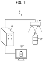
- FIG. 1 is a diagram illustrating an overall configuration of a measurement support system 1 according to a first embodiment of the present disclosure.
- the measurement support system 1 includes a measurement support device 10 (including a display 107) and a three-dimensional measuring device 20 (an example of measuring device).
- the three-dimensional measuring device 20 measures the surface shape of an object 30, which is a three-dimensionally measured object, to obtain the shape measurement data that makes up the surface shape of the object 30.
- the shape measurement data consists of dots.
- a person who performs measurement measures the surface shape of the object 30 while changing the position and direction of the three-dimensional measuring device 20.
- the shape measurement data is the data of the three-dimensional position of a specific point on the surface of the object 30. In order for the three-dimensional position of the specific point to be specified, a predetermined three-dimensional coordinate system need to be set. As long as it is a device that can measure shape measurement data, the three-dimensional measuring device 20 may be any desired device.
- the three-dimensional measuring device 20 may be a laser scanner (three-dimensional scanner) that irradiates an object with a laser beam to measure the distance based on the length of time it takes for the reflected light to return from the object, a stereo camera that estimates the distance based on disparities between a pair of images captured by two separate cameras, a range sensor using active stereo methods that projects pattern light with known structure onto a target object to estimate the distance based on the deflection of the pattern light, a digitizer that measures the distance by detecting the electromagnetic field caused by a source using a stylus whose tip is filled with a coil, and a multi-view stereo device that combines the images captured from multiple views by a monocular camera to measure the surface shape.
- a laser scanner three-dimensional scanner
- the measurement support device 10 is an information processing apparatus that obtains the shape measurement data of the surface shape of the object 30 measured by the three-dimensional measuring device 20 and supports the measurement by presenting the obtained data to a person who performs measurement (displaying the obtained data on the display 107) such that the amount of obtained shape measurement data (i.e., the number of groups of points) can visually be figured out by that user.
- the measurement support device 10 is an information processing apparatus such as a personal computer (PC) or a workstation, or a tablet PC.
- PC personal computer
- a workstation or a tablet PC.
- the shape measurement data can be measured using the camera function provided for a smartphone, such a smartphone may be used as the measurement support device 10 and the three-dimensional measuring device 20.
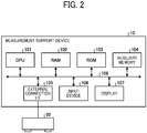
- FIG. 2 is a diagram illustrating a hardware configuration of the measurement support device 10 according to the first embodiment of the present disclosure.
- a hardware configuration of the measurement support device 10 according to the present embodiment is described below with reference to FIG. 2 .
- the CPU 101 causes the operation of the measurement support device 10 in a centralized manner. More specifically, the CPU 101 uses the RAM 102 as a work area, and executes a program stored in, for example, the ROM 103 or the auxiliary memory 104. By so doing, the entire operation of the measurement support device 10 is controlled.
- the RAM 102 is a volatile memory that is used as a work area of the CPU 101.
- the ROM 103 is a nonvolatile memory that stores, for example, various kinds of settings and a program to be executed when the measurement support device 10 is started.
- the auxiliary memory 104 is a nonvolatile storage device that stores various kinds of data such as an operating system (OS), an application program, and the shape measurement data of a measured object.
- the auxiliary memory 104 is a memory such as a hard disk drive (HDD), a solid state disk (SSD), a flash memory, or an optical disk, in which data can electrically, magnetically, or optically be stored.
- HDD hard disk drive
- SSD solid state disk
- flash memory or an optical disk, in which data can electrically, magnetically, or optically be stored.
- the external connection interface 105 is a communication interface that is coupled to an external device such as the three-dimensional measuring device 20.
- the external connection interface 105 is a universal serial bus (USB) interface.
- the input device 106 is an input device through which, for example, texts or numbers are input, various kinds of instructions are selected, and a cursor or pointer is moved.
- the input device 106 may be a mouse or a keyboard.
- the display 107 is a display interface that displays, for example, texts, numbers, various kinds of screen images, an image of a three-dimensionally measured object.
- the display 107 may be a cathode-ray tube (CRT) display, a liquid crystal display (LCD), or an organic electroluminescence (EL) display.
- CTR cathode-ray tube
- LCD liquid crystal display
- EL organic electroluminescence
- the bus 108 is a transmission line that connects the above elements to each other and transmits, for example, address signals, data signals, and various kinds of control signals.
- the hardware configuration of the measurement support device 10 as illustrated in FIG. 2 is given by way of example, and it is not necessary for the measurement support device 10 to include all the elements illustrated in FIG. 2 . Alternatively, the measurement support device 10 may further include other elements not specifically described herein.
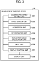
- the measurement support device 10 includes a coordinate system setting unit 201 (construction unit), a space division unit 202 (division unit), an acquisition unit 203, a determination unit 204, an evaluation value calculation unit 205 (calculation unit), an input unit 206, a display control unit 207 (control unit), and a display unit 208.
- the space division unit 202 may be implemented by a program executed by the CPU 101 as illustrated in FIG. 2 .
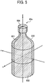
- the display control unit 207 causes a display to display the subareas of the three-dimensionally measured object 30a (i.e., the subareas 501 to 504 in FIG. 5 ) belonging to the multiple subspaces upon color-coding these subareas with different colors, based on the level of evaluation value of each subspace.
- a coloring method for example, dot-shaped objects that indicate the positions of the shape measurement data (dot data) that makes up a three-dimensionally measured object may be colored, or planes that are formed by the line segments connecting the points of the obtained shape measurement data may be colored.
- the green color is emphasized as the evaluation value is higher and the red color is emphasized as the evaluation value is lower, and the yellow color is emphasized when the evaluation value is in the middle.
- the evaluation values improve, and the color is changed from red to yellow, and then changed to green.
- the subareas are color-coded based on the evaluation values as described above, can instantly figure out whether the shape measurement data of each part of the object 30 is sufficient.
- the way of presenting a graph of evaluation values is not limited to a bar graph as illustrated in FIG. 6 .
- the bar graph may be changed to a different type of graph such as a radar chart.
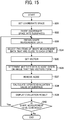
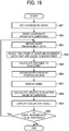
- the acquisition unit 203 of the measurement support device 10 obtains the shape measurement data of the object 30 measured by the three-dimensional measuring device 20. Then, the process shifts to the processes in a step S14.
- the display control unit 207 of the measurement support device 10 causes the display unit 208 to display a three-dimensionally measured object represented by the shape measurement data obtained by the acquisition unit 203.
- the display control unit 207 causes a display to display the evaluation result, i.e., the three-dimensionally measured object in visual presentation where a person who performs measurement can easily and intuitively figure out the situation, based on the evaluation value of the subspace that corresponds to each subarea of the three-dimensionally measured object.
- the display control unit 207 based on the level of evaluation value of each subspace causes a display to display the subareas of the three-dimensionally measured object belonging to the multiple subspaces upon color-coding these subareas with different colors. Then, the process shifts to the processes in a step S16.
- FIG. 8 is a diagram illustrating an example case in which a coordinate system is set based on the distribution of the shape measurement data, in the modification of the first embodiment of the present disclosure.
- the coordinate system setting unit 201 of the measurement support device 10 sets (constructs) the initial three-dimensional coordinate space based on a predetermined reference point. As will be described later, the processes in the steps S11 to S16 are repeated based on the initial three-dimensional coordinate space until three-dimensional coordinate space is newly set by the coordinate system setting unit 201.
- the coordinate system setting unit 201 performs statistical processing on the distribution of the shape measurement data of a three-dimensionally measured object 31a (an example of a measured object) represented by the shape measurement data obtained by the acquisition unit 203, and extracts directions of distribution with large dispersion (i.e., the directions in which the groups of points of the shape measurement data distribute in an extended manner) as coordinate axes.
- directions of distribution in which the dispersion of the shape measurement data is large are extracted as the X-axis and Y-axis, and the direction orthogonal to both the X-axis and Y-axis is determined to be the Z-axis.
- steps S12 to S15 in the present modification of the first embodiment are equivalent to the operations as described above in the first embodiment of the present disclosure. Then, the process shifts to the processes in a step S16.
- the measurement support device 10 As described above, in the measurement support device 10 according to the present modification of the first embodiment of the present disclosure, it is no longer necessary for a person who performs measurement (a technician) to manually determine the coordinate axes for the three-dimensional coordinate space, and consequently the work load can be reduced.
- FIG. 9 is a diagram illustrating a method of setting a reference point of a head according to the second embodiment of the present disclosure.
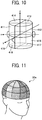
- FIG. 10 is a diagram illustrating an example case in which coordinate space is divided into a plurality of subspaces, according to the second embodiment of the present disclosure.
- FIG. 11 is a three-dimensionally measured object, which corresponds to the object 30 in the above embodiment, is color-coded on a subarea-by-subarea basis, according to the second embodiment of the present disclosure.
- a person who performs measurement uses a digitizer that serves as the three-dimensional measuring device 20 (such a three-dimensional measuring device may be referred to as a digitizer in the following description of the present embodiment) to specify a reference point of the three-dimensional coordinate space in a human head.
- a characteristic bump or dip in the skull which is referred to as an anatomic reference point, may be used as a reference point.
- the anatomic reference point may be, for example, a nasion, a left pre-auricular point (LPA), a right pre-auricular point (RPA), and an external occipital protuberance (inion).
- a nasion, a left pre-auricular point (LPA), and a right pre-auricular point (RPA) are used as reference points.
- a person who performs measurement uses a digitizer (i.e., the three-dimensional measuring device 20) to specify the positions of the nasion, LPA, and RPA of a human head, which is an object to be measured, as positions that serve as the reference points of the three-dimensional coordinate space, and the acquisition unit 203 obtains the shape measurement data of each position.
- the coordinate system setting unit 201 sets the straight line drawn from the LPA to the RPA to be the X-axis. Moreover, the coordinate system setting unit 201 sets the straight line orthogonal to the X-axis and drawn from that orthogonal point to the nasion to be the Y-axis. Moreover, the coordinate system setting unit 201 sets the straight line orthogonal to the X-axis and the Y-axis and drawn from that orthogonal point towards the parietal direction to be the Z-axis. Further, the coordinate system setting unit 201 sets (constructs) the three-dimensional coordinate space that is defined by the X-axis, Y-axis, and the Z-axis as obtained above.
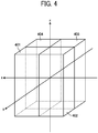
- the space division unit 202 divides the three-dimensional coordinate space set by the coordinate system setting unit 201 into a plurality of subspaces. As illustrated in FIG. 10 , for example, the space division unit 202 separates the three-dimensional coordinate space set by the coordinate system setting unit 201 by each of the xy-plane, the yz-plane, and zx-plane to form eight subspaces (i.e., subspaces 411 to 418).
- the zx-plane may be rotated around the Z-axis to divide the three-dimensional coordinate space with an angle smaller than 90 degrees in the direction perpendicular to the xy-plane.
- the three-dimensional coordinate space is divided into sixteen subspaces.
- the acquisition unit 203 obtains the shape measurement data of the object 30 measured by a digitizer (i.e., the three-dimensional measuring device 20). Then, the acquisition unit 203 stores the obtained shape measurement data in the auxiliary memory 104.
- a digitizer i.e., the three-dimensional measuring device 20
- the acquisition unit 203 stores the obtained shape measurement data in the auxiliary memory 104.
- the shape measurement data of points may be obtained by specifying a point on a one-by-one basis, or the shape measurement data of groups of points may be obtained by sliding a digitizer along the surface shape of a head.
- the operations that are performed by the determination unit 204, the evaluation value calculation unit 205, the input unit 206, and the display unit 208 are equivalent to the operations as described above in the first embodiment of the present disclosure.
- the display control unit 207 causes the display operation of the display unit 208. More specifically, the display control unit 207 causes the display unit 208 to display a three-dimensionally measured object represented by the shape measurement data obtained by the acquisition unit 203. In so doing, the display control unit 207 causes a display to display the three-dimensionally measured object in visual presentation where a person who performs measurement can easily and intuitively figure out the situation, based on the evaluation value of the subspace that corresponds to each subarea of the three-dimensionally measured object. As illustrated in FIG.
- the measurement support device 10 when the measurement support device 10 according to the present embodiment measures the shape of a human head that serves as an object to be measured, three-dimensional coordinate space is constructed using anatomic reference points as reference points. Due to such a configuration, the association between the attitude of a human head and the displayed distribution of the shape measurement data and the evaluation values can easily be figured out.
- FIG. 12 is a diagram illustrating an example case in which the two-dimensionally projected image of a measured object 33a of the object 30 are color-coded, in the modification of the second embodiment of the present disclosure. operations in which the measurement support device 10 according to the modification of the second embodiment of the present disclosure two-dimensionally projects and displays a three-dimensionally measured object when evaluation values are to be displayed are described with reference to FIG. 12 .
- the space division unit 202 divides the coordinate space (xy-plane) set by the coordinate system setting unit 201 into a plurality of subspaces. For example, in the example case as illustrated in FIG. 12 , the space division unit 202 divides the coordinate space (xy-plane) set by the coordinate system setting unit 201 into four subspaces including the first to fourth quadrants. Note that the term "space” in the terms "coordinate space” and "subspace” indicates not only three-dimensional space but also indicates a two-dimensional plane.
- the acquisition unit 203 obtains the shape measurement data of the object 30 measured by the three-dimensional measuring device 20. Then, the acquisition unit 203 stores the obtained shape measurement data in the auxiliary memory 104. In so doing, the display control unit 207 projects the three-dimensionally measured object represented by the shape measurement data obtained by the acquisition unit 203 onto the two-dimensional plane constructed by the coordinate system setting unit 201, and causes the display unit 208 to display the projected image as a two-dimensionally measured object (for example, the measured object 33a as illustrated in FIG. 12 ).
- the determination unit 204 determines to which one of the subspaces of the coordinate space set by the coordinate system setting unit 201 each part (or each area) of the object represented by the shape measurement data (dot data) of the object obtained by the acquisition unit 203 belongs. In other words, the measured object is divided into a plurality of subareas as the determination unit 204 determines to which one of the subspaces each part of the measured object belongs.
- an object 33a that is represented by the shape measurement data of the object obtained by the acquisition unit 203 is illustrated in FIG. 12 .
- the coordinate space (two-dimensional plane) set by the coordinate system setting unit 201 is divided into four subspaces including the first to fourth quadrants in the present modification of the second embodiment, and the measured object 33a is included in the subspaces composed of the first to fourth quadrants.
- the determination unit 204 determines that the subarea 511 belongs to a first quadrant, and determines that the subarea 512 belongs to a second quadrant.
- the determination unit 204 determines that the subarea 513 belongs to a third quadrant, and determines that the subarea 514 belongs to a fourth quadrant.
- a graph of evaluation values (for example, a bar graph) that are associated with the subspaces that correspond to the subareas of the measured object may be displayed near the display area of the measured object.
- the three-dimensional geometric configuration of an object may be used.
- the space in which shape measurement data could exist is limited in view of the knowledge of the geometric configuration of a three-dimensional object, which is obtained beforehand.
- the point of origin of the three-dimensional coordinate system or the distance between the center of gravity and the previously-obtained shape measurement data group may be used.
- a three-dimensional model may be generated based on the known information, and the shape of the generated three-dimensional model may be corrected based on the obtained data.
- the inside of the three-dimensional model as obtained above may be used as space in which the shape measurement data could exist.
- Such a method is advantageous when the object to be measured is spatially apart from the source of noise, as in, for example, reflection or glare of another object. On the other hand, it is difficult to apply such a method to noise existing near the object.
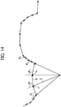
- the angle ⁇ that two displacement vectors form is close to 0 degree or 180 degrees (parallel).
- a predetermined condition is based on, for example, whether
- the angle determination unit 209c determines whether
- the distance determination unit 210d of the noise reduction unit 210 of the measurement support device 10b determines whether the difference between each a plurality of distances calculated by the distance calculation unit 210b and a representative distance obtained by the representative value obtaining unit 210c satisfies a predetermined condition. For example, the distance determination unit 210d determines whether the above difference exceeds a predetermined threshold. Further, the removal unit 210e of the noise reduction unit 210 of the measurement support device 10b determines that the shape measurement data that is determined by the distance determination unit 210d to dissatisfy a predetermined condition involves noise, and removes the shape measurement data as noise. After all the shape measurement data obtained by the acquisition unit 203 goes through the processes in the steps S54 to S57, the process shifts to the processes in a step S58.
Landscapes
- Physics & Mathematics (AREA)
- General Physics & Mathematics (AREA)
- Engineering & Computer Science (AREA)
- Theoretical Computer Science (AREA)
- Computer Vision & Pattern Recognition (AREA)
- Human Computer Interaction (AREA)
- Signal Processing (AREA)
- Length Measuring Devices With Unspecified Measuring Means (AREA)
- Length Measuring Devices By Optical Means (AREA)
Applications Claiming Priority (2)
| Application Number | Priority Date | Filing Date | Title |
|---|---|---|---|
| JP2018047336 | 2018-03-14 | ||
| JP2018092316A JP2019164109A (ja) | 2018-03-14 | 2018-05-11 | 計測装置、計測システム、計測方法およびプログラム |
Publications (2)
| Publication Number | Publication Date |
|---|---|
| EP3540686A2 true EP3540686A2 (de) | 2019-09-18 |
| EP3540686A3 EP3540686A3 (de) | 2019-10-30 |
Family
ID=65685237
Family Applications (1)
| Application Number | Title | Priority Date | Filing Date |
|---|---|---|---|
| EP19160498.2A Withdrawn EP3540686A3 (de) | 2018-03-14 | 2019-03-04 | Messvorrichtung, messsystem, messverfahren und trägermedium mit darauf gespeichertem programmcode |
Country Status (3)
| Country | Link |
|---|---|
| US (1) | US20190285397A1 (de) |
| EP (1) | EP3540686A3 (de) |
| CN (1) | CN110274560A (de) |
Families Citing this family (3)
| Publication number | Priority date | Publication date | Assignee | Title |
|---|---|---|---|---|
| US11612345B2 (en) | 2018-03-15 | 2023-03-28 | Ricoh Company, Ltd. | Input device, measurement system, and computer-readable medium |
| US11906294B2 (en) | 2020-07-28 | 2024-02-20 | Ricoh Company, Ltd. | Alignment apparatus, alignment system, alignment method, and recording medium |
| DE102023124803A1 (de) | 2023-09-14 | 2025-03-20 | AUDI HUNGARIA Zrt. | Kraftfahrzeug, Verfahren zum Bauen eines solchen und System sowie Verfahren mit Nutzung einer Mehrzahl von solchen Kraftfahrzeugen |
Citations (1)
| Publication number | Priority date | Publication date | Assignee | Title |
|---|---|---|---|---|
| JP2014010559A (ja) | 2012-06-28 | 2014-01-20 | Toshiba Corp | 計測支援装置、方法及びプログラム |
Family Cites Families (11)
| Publication number | Priority date | Publication date | Assignee | Title |
|---|---|---|---|---|
| US8520930B2 (en) * | 2008-04-18 | 2013-08-27 | 3D Scanners Ltd. | Method and computer program for improving the dimensional acquisition of an object |
| CN101266694B (zh) * | 2008-04-28 | 2010-06-09 | 武汉大学 | 一种单站地面激光扫描点云的构网方法 |
| ATE519184T1 (de) * | 2008-05-20 | 2011-08-15 | Oticon As | Vorrichtung und verfahren zur darstellung einer gescannten fläche |
| EP2351981B1 (de) * | 2008-11-20 | 2013-07-10 | Asahi Kasei Microdevices Corporation | Vorrichtung zur Messung physikalischer Größen und Verfahren zur Messung physikalischer Größen |
| WO2012141235A1 (ja) * | 2011-04-13 | 2012-10-18 | 株式会社トプコン | 三次元点群位置データ処理装置、三次元点群位置データ処理システム、三次元点群位置データ処理方法およびプログラム |
| JP6192938B2 (ja) * | 2013-01-15 | 2017-09-06 | 株式会社東芝 | 三次元合成処理システムおよび三次元合成処理方法 |
| US9338440B2 (en) * | 2013-06-17 | 2016-05-10 | Microsoft Technology Licensing, Llc | User interface for three-dimensional modeling |
| JP6377536B2 (ja) * | 2015-01-15 | 2018-08-22 | 株式会社東芝 | 空間情報可視化装置、プログラムおよび空間情報可視化方法 |
| US10304256B2 (en) * | 2016-12-13 | 2019-05-28 | Indoor Reality Inc. | Point cloud cleaning method |
| CN107103153B (zh) * | 2017-05-17 | 2023-09-19 | 南怀方 | 一种基于三维激光扫描技术的矿产资源消耗量评估方法 |
| CN107525491A (zh) * | 2017-08-31 | 2017-12-29 | 中煤航测遥感集团有限公司 | 等高线采集方法及终端 |
-
2019
- 2019-02-27 US US16/286,839 patent/US20190285397A1/en not_active Abandoned
- 2019-03-04 EP EP19160498.2A patent/EP3540686A3/de not_active Withdrawn
- 2019-03-07 CN CN201910175539.3A patent/CN110274560A/zh active Pending
Patent Citations (1)
| Publication number | Priority date | Publication date | Assignee | Title |
|---|---|---|---|---|
| JP2014010559A (ja) | 2012-06-28 | 2014-01-20 | Toshiba Corp | 計測支援装置、方法及びプログラム |
Also Published As
| Publication number | Publication date |
|---|---|
| US20190285397A1 (en) | 2019-09-19 |
| EP3540686A3 (de) | 2019-10-30 |
| CN110274560A (zh) | 2019-09-24 |
Similar Documents
| Publication | Publication Date | Title |
|---|---|---|
| JP7632518B2 (ja) | 画像処理装置、画像処理方法、及びプログラム | |
| EP3693836B1 (de) | System und verfahren zum verbinden von virtuellen objekten mit realen umgebungen | |
| KR102661681B1 (ko) | 선호된 포인트들을 식별하고 유지하는 포인트 클라우드들의 병합 방법 | |
| CN114637023B (zh) | 用于激光深度图取样的系统及方法 | |
| US10268917B2 (en) | Pre-segment point cloud data to run real-time shape extraction faster | |
| CN111007485B (zh) | 一种图像处理方法、装置、以及计算机存储介质 | |
| EP3467790A1 (de) | Informationsverarbeitungsvorrichtung, informationsverarbeitungsmethode, und speichermedium | |
| EP3540686A2 (de) | Messvorrichtung, messsystem, messverfahren und trägermedium mit darauf gespeichertem programmcode | |
| US20160063669A1 (en) | Dynamic Motion Path Blur User Interface | |
| US11490062B2 (en) | Information processing apparatus, information processing method, and storage medium | |
| US11297301B2 (en) | Image capturing system, arrangement determination apparatus, arrangement determination method, and storage medium | |
| CN110378174A (zh) | 道路线提取方法和装置 | |
| CN109479086B (zh) | 相对于物体变焦的方法和设备 | |
| JP2019164109A (ja) | 計測装置、計測システム、計測方法およびプログラム | |
| JP2016220198A (ja) | 情報処理装置、方法、プログラム | |
| CN110795978A (zh) | 路面点云数据提取方法、装置、存储介质及电子设备 | |
| CN112833775B (zh) | 物体包装体积的检测方法、装置、终端及可读存储介质 | |
| CN114266876A (zh) | 定位方法、视觉地图的生成方法及其装置 | |
| JP7787752B2 (ja) | 形状推定装置、処理方法、およびプログラム | |
| CN116563505B (zh) | 虚拟形象生成方法、装置、电子设备以及存储介质 | |
| CN112102391A (zh) | 测量方法及装置、电子设备及存储介质 | |
| CN117765094A (zh) | 输电线路的相机外参标定方法、装置、设备及存储介质 | |
| CN109978982A (zh) | 一种基于倾斜影像的点云快速上色方法 | |
| US20200242819A1 (en) | Polyline drawing device | |
| EP4310784A1 (de) | Bildverarbeitungsvorrichtung, bildverarbeitungsverfahren und programm |
Legal Events
| Date | Code | Title | Description |
|---|---|---|---|
| PUAI | Public reference made under article 153(3) epc to a published international application that has entered the european phase |
Free format text: ORIGINAL CODE: 0009012 |
|
| STAA | Information on the status of an ep patent application or granted ep patent |
Free format text: STATUS: REQUEST FOR EXAMINATION WAS MADE |
|
| 17P | Request for examination filed |
Effective date: 20190304 |
|
| AK | Designated contracting states |
Kind code of ref document: A2 Designated state(s): AL AT BE BG CH CY CZ DE DK EE ES FI FR GB GR HR HU IE IS IT LI LT LU LV MC MK MT NL NO PL PT RO RS SE SI SK SM TR |
|
| AX | Request for extension of the european patent |
Extension state: BA ME |
|
| PUAL | Search report despatched |
Free format text: ORIGINAL CODE: 0009013 |
|
| AK | Designated contracting states |
Kind code of ref document: A3 Designated state(s): AL AT BE BG CH CY CZ DE DK EE ES FI FR GB GR HR HU IE IS IT LI LT LU LV MC MK MT NL NO PL PT RO RS SE SI SK SM TR |
|
| AX | Request for extension of the european patent |
Extension state: BA ME |
|
| RIC1 | Information provided on ipc code assigned before grant |
Ipc: G06T 7/55 20170101ALI20190923BHEP Ipc: G06T 5/00 20060101AFI20190923BHEP |
|
| STAA | Information on the status of an ep patent application or granted ep patent |
Free format text: STATUS: EXAMINATION IS IN PROGRESS |
|
| 17Q | First examination report despatched |
Effective date: 20200604 |
|
| STAA | Information on the status of an ep patent application or granted ep patent |
Free format text: STATUS: THE APPLICATION IS DEEMED TO BE WITHDRAWN |
|
| 18D | Application deemed to be withdrawn |
Effective date: 20230704 |