EP3540422A1 - Monolithic gas sensor arrangement, manufacturing method and measurement method - Google Patents
Monolithic gas sensor arrangement, manufacturing method and measurement method Download PDFInfo
- Publication number
- EP3540422A1 EP3540422A1 EP18161786.1A EP18161786A EP3540422A1 EP 3540422 A1 EP3540422 A1 EP 3540422A1 EP 18161786 A EP18161786 A EP 18161786A EP 3540422 A1 EP3540422 A1 EP 3540422A1
- Authority
- EP
- European Patent Office
- Prior art keywords
- transducer
- sensitive layer
- sensor arrangement
- measurement signal
- measurement
- Prior art date
- Legal status (The legal status is an assumption and is not a legal conclusion. Google has not performed a legal analysis and makes no representation as to the accuracy of the status listed.)
- Granted
Links
Images




Classifications
-
- G—PHYSICS
- G01—MEASURING; TESTING
- G01N—INVESTIGATING OR ANALYSING MATERIALS BY DETERMINING THEIR CHEMICAL OR PHYSICAL PROPERTIES
- G01N27/00—Investigating or analysing materials by the use of electric, electrochemical, or magnetic means
- G01N27/02—Investigating or analysing materials by the use of electric, electrochemical, or magnetic means by investigating impedance
- G01N27/22—Investigating or analysing materials by the use of electric, electrochemical, or magnetic means by investigating impedance by investigating capacitance
- G01N27/223—Investigating or analysing materials by the use of electric, electrochemical, or magnetic means by investigating impedance by investigating capacitance for determining moisture content, e.g. humidity
-
- G—PHYSICS
- G01—MEASURING; TESTING
- G01N—INVESTIGATING OR ANALYSING MATERIALS BY DETERMINING THEIR CHEMICAL OR PHYSICAL PROPERTIES
- G01N33/00—Investigating or analysing materials by specific methods not covered by groups G01N1/00 - G01N31/00
- G01N33/0004—Gaseous mixtures, e.g. polluted air
- G01N33/0009—General constructional details of gas analysers, e.g. portable test equipment
- G01N33/0027—General constructional details of gas analysers, e.g. portable test equipment concerning the detector
- G01N33/0031—General constructional details of gas analysers, e.g. portable test equipment concerning the detector comprising two or more sensors, e.g. a sensor array
-
- G—PHYSICS
- G01—MEASURING; TESTING
- G01N—INVESTIGATING OR ANALYSING MATERIALS BY DETERMINING THEIR CHEMICAL OR PHYSICAL PROPERTIES
- G01N27/00—Investigating or analysing materials by the use of electric, electrochemical, or magnetic means
- G01N27/02—Investigating or analysing materials by the use of electric, electrochemical, or magnetic means by investigating impedance
- G01N27/04—Investigating or analysing materials by the use of electric, electrochemical, or magnetic means by investigating impedance by investigating resistance
- G01N27/12—Investigating or analysing materials by the use of electric, electrochemical, or magnetic means by investigating impedance by investigating resistance of a solid body in dependence upon absorption of a fluid; of a solid body in dependence upon reaction with a fluid, for detecting components in the fluid
- G01N27/121—Investigating or analysing materials by the use of electric, electrochemical, or magnetic means by investigating impedance by investigating resistance of a solid body in dependence upon absorption of a fluid; of a solid body in dependence upon reaction with a fluid, for detecting components in the fluid for determining moisture content, e.g. humidity, of the fluid
Definitions
- the present disclosure relates to a sensor arrangement, to a manufacturing method and to a measurement method.
- the sensor arrangement is configured as a chemical sensor arrangement and designed for the measurement of a parameter in a gas or liquid.
- the sensor arrangement may be realized for the detection of humidity, i.e. for the detection of water molecules in air.
- the sensitive layer is configured to absorb gas molecules. The property of the sensitive layer in such a sensor determines the quality of the measurement.
- the improved concept is based on the idea of a monolithic gas sensor arrangement having multiple transducers with different properties. This arrangement can provide an accurate measurement over a broader range of the gas parameter to be measured compared to a sensor with a single transducer. Alternatively or in addition to enhanced accuracy, a faster accurate measurement can be enabled.
- the improved concept proposes a sensor arrangement having a first transducer with a first sensitive layer and a second transducer with a second sensitive layer, wherein the first and the second sensitive layer differ from each other in at least one property.
- the monolithic sensor arrangement according to the improved concept further comprises a readout circuit that generates a first measurement signal depending on the capacitance of the first transducer and a second measurement signal depending on the capacitance of the second transducer.
- the improved concept further comprises a method for generating a result signal by means of the readout circuit of such a sensor arrangement depending on the first and the second measurement signal, from which the gas parameter to be measured can be derived.
- the first and the second sensitive layer are of a dielectric material and configured to absorb water molecules from the surrounding gas.
- the dielectric material of the first and the second sensitive layer can be chosen such that the dielectric constant of water is much higher than that of the dielectric material. Consequently, the measurable change in capacitance is directly proportional to the relative humidity.
- some implementations may for example comprise interdigitated electrodes of the respective transducer with the sensitive layer in between and in the same plane.
- the electrodes may form a parallel-plate capacitor with the sensitive layer in between the parallel plates.
- the first and the second sensitive layer may be of different materials.
- Dielectric materials for sensitive layers in capacitive gas sensors include polymers, such as polyimides. Different polymers can show non-identical sensitivities in different relative humidity regimes, for example a different absorption behavior. In particular, this means that one polymer could be more sensitive at low relative humidity while the other polymer is more sensitive at high relative humidity.
- the response time of a transducer depends on the diffusion coefficient of the sensitive layer material. Having the first and the second sensitive layer made of different polymers with different diffusion coefficients hence allows for the realization of different response times of the first and the second transducer.
- the first and the second sensitive layer can alternatively or in addition be of different thicknesses.
- Capacitive transducers can be designed such that their response time is proportional to the thickness of the dielectric material. Choosing different thicknesses for the first and the second sensitive layer allows for a sensor arrangement with the first and the second transducer having different response times.
- a transducer with a very thin sensitive layer may become susceptible to inaccuracies, for example due to surface contaminations. These inaccuracies occur if electric field lines of the capacitive transducer are no longer fully confined within the sensitive layer. Above a certain threshold of the thickness, the sensitive layer confines the electric field lines, hence enabling accurate measurements.
- the first transducer can for example be chosen to have a thin layer dielectric material and therefore a fast response time, while the second transducer may possess a thicker sensitive layer and therefore be slower but deliver more accurate results. Depending on the requirements of the application, this allows for simultaneous fast and accurate measurements in contrast to a single transducer sensor, for which a compromise has to be made.
- the readout circuit may be configured to generate a result signal as a predefined function of the first and the second measurement signal. Since the first and the second transducer are configured to measure the same quantity, a single result signal may be desired as the output of the readout circuit.
- the readout circuit in such an embodiment may for example apply the predefined function to the first and the second measurement signal in order to give preference to one measurement signal over the other.
- the predefined function can be a weighted arithmetic mean or comprise filter functions.
- the predefined function can be tailored such to achieve an enhanced measurement result compared to a single-transducer sensor, for example in terms of accuracy and/or measurement rate.
- the readout circuit further comprises a memory which stores data that describes the first and the second transducer.
- the data characterizes accuracy and/or response time of the first and the second transducer depending on relative humidity.
- the data can hereby either comprise functions or lookup tables.
- the readout circuit generates the result signal from the first and the second measurement signal and the data stored in the memory.
- the data can be used to convert capacitances into units of relative humidity.
- the memory may comprise lookup tables or functions for a first and a second coefficient, C 1 and C 2 .
- C 1 and C 2 can for example be used by means of the readout circuit as weight factors for calculating the weighted arithmetic mean for determining the result signal from the first and the second measurement signal.
- C 1 and C 2 depend on relative humidity (RH). Functions or lookup tables for C 1 (RH) and C 2 (RH) can be obtained by prior characterization measurements of the first and the second transducer and be saved in the memory.
- RH C 1 RH init RH 1 + C 2 RH init RH 2 .
- This process may be repeated multiple times by means of the readout circuit to further enhance the estimate which is eventually output as the result signal.
- This procedure leads to an enhanced accuracy of the relative humidity measurement over the entire range especially if the first and the second transducer are designed for operation in different regimes of the relative humidity range. Hence, this procedure is of particular relevance for embodiments, in which the first and the second sensitive layer differ from each other in terms of the material.
- the data stored in the memory comprises a first frequency dependent filter function which is applied to the first measurement signal by means of the readout circuit and a second frequency dependent filter function which is applied to the second measurement signal by means of the readout circuit for generating the result signal.
- Frequency dependent filter functions may be useful if, for example, the first and the second transducer possess different polymer thicknesses.
- an accurate measurement of the relative humidity can be obtained from the transducer with the thicker polymer, while the transducer with the thinner polymer has a larger bandwidth, i.e. response rate, and therefore is able to follow fast changes in relative humidity.
- a combination of both measurement signals using appropriate filter functions enables fast and accurate relative humidity measurements.
- the first and the second filter function can be obtained by prior characterization measurements of the first and the second transducer and be saved in the memory.
- the same procedure can be applied to the first and the second transducer to account for measurement uncertainties, such as for example drift, which typically is limited to low-frequency components in the measurement signal.
- the first transducer may have a smaller drift compared to the second transducer but a larger noise component, which is usually a white noise, i.e. has a constant power spectral density with respect to frequency.
- the readout circuit applies the first and the second filter function as to put more weight on low-frequency components from the first transducer and accordingly more weight on high-frequency components from the second transducer.
- the aforementioned object is further solved by a method of manufacturing a monolithic gas sensor arrangement.
- the method comprises manufacturing a first transducer on a substrate with the first transducer comprising a first sensitive layer.
- the method further comprises manufacturing a second transducer on the substrate with the second transducer comprising a second sensitive layer.
- the first and the second sensitive layer are characterized in that they differ from each other in at least one property.
- the differing property of the first and the second sensitive layer may for example be the thickness and/or the material.
- the method may further comprise manufacturing a readout circuit on the substrate, with the readout circuit being configured to generate measurement signals based on the first and the second transducer.
- the aforementioned object is further solved by a method of generating a result signal from a capacitive gas sensor arrangement having a first transducer with a first sensitive layer and a second transducer with a second sensitive layer, wherein the first and the second sensitive layer differ from each other in at least one property.
- the method comprises the generation of a first and second measurement signal based on the capacitance of the respective transducer and generating a result signal by application of a predefined function, for example by means of a readout circuit.
- the method may utilize a memory that stores data characterizing the first and the second transducer.
- This characterization data may for example describe the measurement-dependent and/or frequency-dependent sensitivities of the first and the second transducer. This data can be used to generate the result signal.
- the data stored in the memory comprises weight factors used to determine a weighted arithmetic mean of the first and the second measurement signal and generate the result signal from this weighted arithmetic mean.
- a weighted arithmetic mean may enable a more accurate measurement over a broader range compared to a single-transducer measurement.
- the data in the memory may comprise a first and a second frequency-dependent filter function used to generate the result signal.
- filter functions allow to combine the first and the second measurement signal in order to achieve an enhanced accuracy at a higher measurement rate compared to a single-transducer measurement.
- Figure 1A shows an exemplary embodiment of a monolithic sensor arrangement 1 comprising a first transducer 11 and a second transducer 12 on a substrate 10.
- the first transducer 11 comprises a first electrode line 13 and a second electrode line 14.
- the first and the second electrode line 13, 14 are arranged inside a first sensitive layer 17 in an interdigitated manner.
- the second transducer 12 comprises a third electrode line 15 and a fourth electrode line 16.
- the third and the fourth electrode line 15, 16 are arranged inside a second sensitive layer 18 in an interdigitated manner.
- the first and the second sensitive layer 17, 18 may be a dielectric, such as a polymer. In particular, the first and the second sensitive layer 17, 18 may be of different materials.
- Figure 1B shows the cross-section of the exemplary embodiments shown in figure 1A .
- the first and the second electrode line 13, 14 of the first transducer 11 are surrounded by the first sensitive layer 17.
- the third and the fourth electrode line 15, 16 of the second transducer 12 are surrounded by the second sensitive layer 18.
- the first sensitive layer 17 has an interface 19 to an ambient gas 21.
- the second sensitive layer 18 has an interface 20 to the ambient gas 21.
- the ambient gas 21 comprises the parameter to be detected, such as water molecules, i.e. relative humidity, or another target gas.
- the first and the second electrode line 13 and 14 of the first transducer 11 form in this embodiment an interdigitated capacitor.
- the polymers 17 and 18 are configured to absorb water molecules from the ambient gas 21 via the interfaces 19 and 20.
- the materials possess dielectric constants significantly lower than that of water.
- the dielectric properties, i.e. the effective dielectric constant, of the first and the second sensitive layer 17 and 18 are modified. This causes the measured capacitances between the first and the second electrode line 13 and 14 of the first transducer 11 and between the third and the fourth electrode line 15 and 16 of the second transducer 12 to change in a detectable manner.
- the changes in capacitance are in this embodiment proportional to the relative humidity of the ambient gas 21.
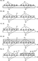
- Figures 2A to 2E show example steps of a manufacturing method of this embodiment.
- a first material is applied ( figure 2B ) and structured ( figure 2C ) to form the first sensitive layer 17 embedding the first and the second electrode line 13, 14.
- a second material is applied ( figure 2D ) and structured ( figure 2E ), forming the second sensitive layer 18 embedding the third and the fourth electrode line 15, 16, as illustrated in figures 2D and 2E .
- another exemplary embodiment of the sensor arrangement 1 comprises parallel-plate capacitors as the first and second transducer, as shown in figure 1C .
- two parallel plate electrodes form the respective capacitor with a dielectric material, such as a polymer, in between the electrodes.
- a first material is applied and structured to form the first sensitive layer 17.
- a second material forming the second sensitive layer 18 is applied and structured.
- the second and the fourth electrode line 14, 16 are applied and structured to finalize the first and the second parallel-plate transducer 11, 12.
- two different dielectrics are employed as the first and the second sensitive layer 17 and 18.
- these two materials can be configured such that they possess their peak sensitivities in different regimes of relative humidity, respectively. Using this embodiment accurate measurements across a broader humidity range can be achieved.
- first and the second sensitive layer 17, 18 may be of the same dielectric material but with different thicknesses, as shown in figures 3A and 3B for an interdigitated electrode layout.
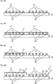
- Figures 4A to 4D show example steps of a manufacturing method of this embodiment. After realization of the interdigitated electrode lines 13 to 16 on the substrate 10 ( figure 4A ), a dielectric material is applied ( figure 4B ) and structured ( figure 4C ) to form a first part of the first sensitive layer 17 embedding the first and the third electrode line 13, 14.
- the same dielectric material is applied and structured again ( figure 4D ) to form both the second sensitive layer 18 surrounding the third and the fourth electrode line 15, 16 and a second part of the first sensitive layer 17.
- a parallel-plate capacitor design is also possible for an embodiment with different thicknesses, as shown in figure 3C .
- the manufacturing steps for the parallel-plate design follow from the example described and shown in figure 1C .
- the response time of a capacitive transducer is proportional to its thickness. This means that the thinner a sensitive layer in a capacitive transducer is, the better it can follow fast changes in relative humidity.
- the lower boundary for the thickness of a sensitive layer is hereby given by the point at which electric field lines of the electrodes begin to lose confinement by the sensitive layer. In this case a measurement of the capacitance becomes susceptible to surface effects as source of error.
- a typical dimension for the thickness of the thin sensitive layer in the described embodiment is in the order of a few micrometers, allowing measurements of the capacitance with sufficient accuracy with measurement times of approximately 200ms. This is significantly shorter than changes in relative humidity typically occur.
- a sensor arrangement 1 may comprise the first transducer 11 having a standard thickness polymer as sensitive layer 17, e.g. several micrometers, e.g. 4-5 micrometers thick, while the second sensitive layer 18 is significantly thinner, for example less than 3 micrometers.
- a measurement of the first transducer 11 yields a high-accuracy measurement of the relative humidity, while a fast measurement of the second transducer 12 enables to track fast changes of this quantity.
- Figure 5 shows a monolithic sensor arrangement comprising a first and a second capacitive transducer 11, 12 and a readout circuit 30 on a substrate 10, for example a chip substrate.
- the readout circuit 30 is electrically coupled to the first electrode line 13, the second electrode line 14, the third electrode line 15 and the fourth electrode line 16.
- the readout circuit 30 comprises a capacitance-to-digital converter 31, abbreviated converter.
- the converter 31 is electrically coupled to the first, second, third and fourth electrode lines 13 to 16.
- the readout circuit 30 further comprises a digital processor 32 that is coupled on its input side to the converter 31.
- the readout circuit 30 further comprises a memory 33 that is coupled to the digital processor 32.
- the readout circuit 30 comprises a switching arrangement 34.
- a control input of the switching arrangement 34 is coupled to an output of the digital processor 32.
- the switching arrangement 34 comprises a first changeover switch 35 having a first input connected to the first electrode line 13, a second input connected to the third electrode line 15 and an output connected to a first input 36 of the converter 31.
- the switching arrangement 34 comprises a second changeover switch 37 with a first input connected to the second electrode line 14, a second input connected to the fourth electrode line 16 and an output connected to a second input 38 of the converter 31.
- the first electrode line 13 is coupled to the first input 36 of the converter 31 via the first changeover switch 35, while the second electrode line 14 is coupled to the second input 38 of the converter 31 via the second changeover switch 37.
- the converter 31 generates a first measurement signal, which is a function of the capacitance between the first electrode line 13 and the second electrode line 14.
- the third electrode line 15 is coupled via the first changeover switch 35 to the first input 36 of the converter 31, while the fourth electrode line 16 is coupled to the second input 38 of the converter 31 via the second changeover switch 37.
- the converter 31 generates a second measurement signal, which is a function of the capacitance between the third electrode line 15 and the fourth electrode line 16.
- the first and the second measurement signal are provided to the digital processor 32.
- the output of the second changeover switch 37 is connected to a reference potential terminal.
- the second and the fourth electrode lines 14, 16 are directly connected to a reference potential terminal.
- the second changeover switch 37 in such an embodiment is omitted.
- the digital processor 32 generates a result signal at an output 39.
- the result signal may be realized as a humidity signal.
- the humidity signal provides information about the relative humidity in the ambient gas 21.
- the result signal is determined by the digital processor 32 using the first and the second measurement signal and data stored in the memory 33.
- the memory 33 may store parameters of functions or a lookup table which are used for the calculation of the result signal using the first and the second measurement signal as inputs.
- the parameter of the functions or lookup table may be stored in a non-volatile block of the memory 33 such as an electrically erasable programmable read-only memory, abbreviated EEPROM, or a one-time programmable memory, abbreviated OTP.
- the first and the second measurement signal are generated in separate phases, as described above. This implies that they are generated at separate points in time and the digital processor 32 may be in this case configured to store intermediate values, for example the first and the second measurement signal, in a volatile block of the memory 33.
- the readout circuit is configured to generate the first and the second measurement signal simultaneously.
- the result signal can for example be a weighted arithmetic mean with the weight factors stored in the memory 33.
- This method is employed in particular for the embodiment described in figures 1A to 1C , in which different materials for the first and the second sensitive layer 17, 18 are used in order to design the first and the second transducer 11, 12 to have a selective accuracy for certain relative humidity regimes.
- the first transducer 11 may be designed to be sensitive at high relative humidity, while the second transducer 12 may be sensitive at low relative humidity, as shown in figures 6A and 6B .
- Figure 6A shows the measurement (circles) of the capacitance of a first exemplary transducer 11 with respect to relative humidity together with a fit 41 (solid line). From this fit the slope 42 of the capacitance behavior is obtained via derivation, representing the sensitivity of the first transducer 11. In this example, the first transducer 11 is more sensitive at high relative humidity.
- An analogous measurement of an exemplary second transducer 12 is shown in figure 6B as the capacitance versus relative humidity 43 and its slope 44. In contrast to the first transducer 11, the second transducer 12 is in this case more sensitive at low relative humidity.
- Figure 7A shows combining coefficients, i.e. weight factors, determined from the above mentioned measurement.
- the lines show the coefficients 51, 52 determined for the respective transducer 11, 12. With these coefficients the result signal can be calculated as a weighted arithmetic mean from the first and the second measurement signal by means of the digital processor 32 in order to maximize the signal-to-noise ratio of a relative humidity measurement.
- Figure 7B shows the resulting accuracy 53, 54 in terms of the signal-to-noise ratio (SNR) of the first and the second transducer 11, 12 and the SNR 55 after combining the first and the second measurement signal by means of a weighted arithmetic mean.
- the SNR of the result signal is larger than that of the first and the second measurement signal over the entire relative humidity range.
- the gain in SNR is in this example a factor of 2.
- the result signal is generated by means of the digital processor 32 with the focus on compensating differences in drift properties and/or noise properties.
- the data in the memory 33 may comprise a lookup table or parameters for a first and a second filter function.
- Figure 8A shows typical exemplary noise properties and drift properties of a first and a second transducer 11, 12 with respect to frequency.
- the drifts versus frequency 61 and 63 of the respective transducer 11, 12 and their noise versus frequency 62, 64 are shown.
- drifts of capacitive transducers only occur at low rates, i.e. low frequencies, while they are susceptible to white noise that is independent of frequency.
- the first and the second filter functions are determined in order to maximize the signal-to-noise ratio with respect to frequency.
- Figure 8B shows the determined first and second filter function 65 and 66 for the respective transducer. Owing to its smaller drift, the first transducer 11 is preferred at low frequencies, while the second transducer 12 gives the better result at high frequencies due to its lower noise.
- Figure 8C shows the SNR 67 and 68 of the respective transducer with respect to frequency and the resulting SNR 69 after generating the result signal by means of applying the first and the second filter function.
- the first and the second filter function can be applied to the first and the second measurement signal, respectively, to generate the result signal by means of the digital processor 32.
- the first transducer 11 can for example have a standard thickness polymer as the first sensitive layer 17 and hence provide accurate measurements but at limited bandwidth, while the second transducer 12 may have a thin polymer as sensitive layer 18 and provide fast measurements, i.e. be able to follow quick changes in relative humidity.
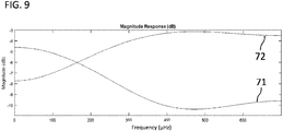
- Figure 9 shows an example of the first and the second filter function 71 and 72 for the respective transducer determined for such an embodiment with the aim of increasing the SNR of the result signal across frequencies of relevance. This procedure is analogous to the case described above, in which the drift and noise properties of the first and second transducer 11, 12 are accounted for.
Landscapes
- Chemical & Material Sciences (AREA)
- Health & Medical Sciences (AREA)
- Life Sciences & Earth Sciences (AREA)
- Analytical Chemistry (AREA)
- General Health & Medical Sciences (AREA)
- Pathology (AREA)
- Immunology (AREA)
- Physics & Mathematics (AREA)
- General Physics & Mathematics (AREA)
- Biochemistry (AREA)
- Engineering & Computer Science (AREA)
- Chemical Kinetics & Catalysis (AREA)
- Electrochemistry (AREA)
- Combustion & Propulsion (AREA)
- Medicinal Chemistry (AREA)
- Food Science & Technology (AREA)
- Investigating Or Analyzing Materials By The Use Of Electric Means (AREA)
Abstract
Description
- The present disclosure relates to a sensor arrangement, to a manufacturing method and to a measurement method.
- The sensor arrangement is configured as a chemical sensor arrangement and designed for the measurement of a parameter in a gas or liquid. For example, the sensor arrangement may be realized for the detection of humidity, i.e. for the detection of water molecules in air.
- For chemical measurements often capacitive sensors with a sensitive layer are used. For the measurement of parameters in a gas, the sensitive layer is configured to absorb gas molecules. The property of the sensitive layer in such a sensor determines the quality of the measurement.
- It is an object of the invention to provide an improved concept for a sensor arrangement and a method for generating measurement results which enable an enhanced measurement quality.
- This object is achieved with the subject matter of the independent claims. Embodiments and developments of the improved concept are defined in the dependent claims.
- The improved concept is based on the idea of a monolithic gas sensor arrangement having multiple transducers with different properties. This arrangement can provide an accurate measurement over a broader range of the gas parameter to be measured compared to a sensor with a single transducer. Alternatively or in addition to enhanced accuracy, a faster accurate measurement can be enabled.
- In particular, the improved concept proposes a sensor arrangement having a first transducer with a first sensitive layer and a second transducer with a second sensitive layer, wherein the first and the second sensitive layer differ from each other in at least one property. The monolithic sensor arrangement according to the improved concept further comprises a readout circuit that generates a first measurement signal depending on the capacitance of the first transducer and a second measurement signal depending on the capacitance of the second transducer.
- The improved concept further comprises a method for generating a result signal by means of the readout circuit of such a sensor arrangement depending on the first and the second measurement signal, from which the gas parameter to be measured can be derived.
- Various embodiments of the sensor arrangement according to the improved concept are configured to measure relative humidity. In such embodiments the first and the second sensitive layer are of a dielectric material and configured to absorb water molecules from the surrounding gas. The dielectric material of the first and the second sensitive layer can be chosen such that the dielectric constant of water is much higher than that of the dielectric material. Consequently, the measurable change in capacitance is directly proportional to the relative humidity.
- For the measurement of the aforementioned capacitance and its change respectively, some implementations may for example comprise interdigitated electrodes of the respective transducer with the sensitive layer in between and in the same plane.
- Alternatively to an interdigitated capacitor, in some implementations the electrodes may form a parallel-plate capacitor with the sensitive layer in between the parallel plates.
- In various embodiments the first and the second sensitive layer may be of different materials. Dielectric materials for sensitive layers in capacitive gas sensors include polymers, such as polyimides. Different polymers can show non-identical sensitivities in different relative humidity regimes, for example a different absorption behavior. In particular, this means that one polymer could be more sensitive at low relative humidity while the other polymer is more sensitive at high relative humidity. Moreover, the response time of a transducer depends on the diffusion coefficient of the sensitive layer material. Having the first and the second sensitive layer made of different polymers with different diffusion coefficients hence allows for the realization of different response times of the first and the second transducer.
- In some embodiments, the first and the second sensitive layer can alternatively or in addition be of different thicknesses. Capacitive transducers can be designed such that their response time is proportional to the thickness of the dielectric material. Choosing different thicknesses for the first and the second sensitive layer allows for a sensor arrangement with the first and the second transducer having different response times.
- While having a fast response time, a transducer with a very thin sensitive layer may become susceptible to inaccuracies, for example due to surface contaminations. These inaccuracies occur if electric field lines of the capacitive transducer are no longer fully confined within the sensitive layer. Above a certain threshold of the thickness, the sensitive layer confines the electric field lines, hence enabling accurate measurements.
- For the described embodiments, the first transducer can for example be chosen to have a thin layer dielectric material and therefore a fast response time, while the second transducer may possess a thicker sensitive layer and therefore be slower but deliver more accurate results. Depending on the requirements of the application, this allows for simultaneous fast and accurate measurements in contrast to a single transducer sensor, for which a compromise has to be made.
- In some embodiments the readout circuit may be configured to generate a result signal as a predefined function of the first and the second measurement signal. Since the first and the second transducer are configured to measure the same quantity, a single result signal may be desired as the output of the readout circuit.
- Depending on the properties of the first and the second transducer the readout circuit in such an embodiment may for example apply the predefined function to the first and the second measurement signal in order to give preference to one measurement signal over the other. For example, the predefined function can be a weighted arithmetic mean or comprise filter functions. In such an embodiment, the predefined function can be tailored such to achieve an enhanced measurement result compared to a single-transducer sensor, for example in terms of accuracy and/or measurement rate.
- In some embodiments the readout circuit further comprises a memory which stores data that describes the first and the second transducer. For example, the data characterizes accuracy and/or response time of the first and the second transducer depending on relative humidity. The data can hereby either comprise functions or lookup tables.
- In such an embodiment the readout circuit generates the result signal from the first and the second measurement signal and the data stored in the memory. For example, the data can be used to convert capacitances into units of relative humidity.
- Alternatively or in addition to conversion data, the memory may comprise lookup tables or functions for a first and a second coefficient, C1 and C2. C1 and C2 can for example be used by means of the readout circuit as weight factors for calculating the weighted arithmetic mean for determining the result signal from the first and the second measurement signal. In particular, for two transducers with for example selective accuracy over the relative humidity range, C1 and C2 depend on relative humidity (RH). Functions or lookup tables for C1(RH) and C2(RH) can be obtained by prior characterization measurements of the first and the second transducer and be saved in the memory.
- In order for the readout circuit to determine the optimal weight factor C1 and C2 for the generation of the result signal after the first and the second measurement signal have been generated by means of the readout circuit, a recursive procedure can be applied. First, an equal weight for the first and the second measurement signal, RH1 and RH2, is assumed in order to obtain an initial estimate RHinit of the relative humidity,

- Using the initial estimate, an updated and more accurate estimate for the relative humidity RH is obtained via,

- This process may be repeated multiple times by means of the readout circuit to further enhance the estimate which is eventually output as the result signal.
- This procedure leads to an enhanced accuracy of the relative humidity measurement over the entire range especially if the first and the second transducer are designed for operation in different regimes of the relative humidity range. Hence, this procedure is of particular relevance for embodiments, in which the first and the second sensitive layer differ from each other in terms of the material.
- In some embodiments the data stored in the memory comprises a first frequency dependent filter function which is applied to the first measurement signal by means of the readout circuit and a second frequency dependent filter function which is applied to the second measurement signal by means of the readout circuit for generating the result signal.
- Frequency dependent filter functions may be useful if, for example, the first and the second transducer possess different polymer thicknesses. In such an embodiment an accurate measurement of the relative humidity can be obtained from the transducer with the thicker polymer, while the transducer with the thinner polymer has a larger bandwidth, i.e. response rate, and therefore is able to follow fast changes in relative humidity. A combination of both measurement signals using appropriate filter functions enables fast and accurate relative humidity measurements. The first and the second filter function can be obtained by prior characterization measurements of the first and the second transducer and be saved in the memory.
- The same procedure can be applied to the first and the second transducer to account for measurement uncertainties, such as for example drift, which typically is limited to low-frequency components in the measurement signal.
- For example, the first transducer may have a smaller drift compared to the second transducer but a larger noise component, which is usually a white noise, i.e. has a constant power spectral density with respect to frequency. In this case for the generation of the result signal the readout circuit applies the first and the second filter function as to put more weight on low-frequency components from the first transducer and accordingly more weight on high-frequency components from the second transducer.
- The aforementioned object is further solved by a method of manufacturing a monolithic gas sensor arrangement.
- The method comprises manufacturing a first transducer on a substrate with the first transducer comprising a first sensitive layer. The method further comprises manufacturing a second transducer on the substrate with the second transducer comprising a second sensitive layer. The first and the second sensitive layer are characterized in that they differ from each other in at least one property.
- The differing property of the first and the second sensitive layer may for example be the thickness and/or the material.
- The method may further comprise manufacturing a readout circuit on the substrate, with the readout circuit being configured to generate measurement signals based on the first and the second transducer.
- The aforementioned object is further solved by a method of generating a result signal from a capacitive gas sensor arrangement having a first transducer with a first sensitive layer and a second transducer with a second sensitive layer, wherein the first and the second sensitive layer differ from each other in at least one property.
- The method comprises the generation of a first and second measurement signal based on the capacitance of the respective transducer and generating a result signal by application of a predefined function, for example by means of a readout circuit.
- In some embodiments the method may utilize a memory that stores data characterizing the first and the second transducer. This characterization data may for example describe the measurement-dependent and/or frequency-dependent sensitivities of the first and the second transducer. This data can be used to generate the result signal.
- In an embodiment the data stored in the memory comprises weight factors used to determine a weighted arithmetic mean of the first and the second measurement signal and generate the result signal from this weighted arithmetic mean.
- For example, if the first and the second transducer possess different selective accuracies across the measurement range, a weighted arithmetic mean may enable a more accurate measurement over a broader range compared to a single-transducer measurement.
- Alternatively or in addition, the data in the memory may comprise a first and a second frequency-dependent filter function used to generate the result signal.
- For example, if the first and the second transducer have different measurement response rates, filter functions allow to combine the first and the second measurement signal in order to achieve an enhanced accuracy at a higher measurement rate compared to a single-transducer measurement.
- Further embodiments of the methods become apparent to the skilled person from the embodiments of the sensor arrangement described above.
- The following description of figures of example embodiments may further illustrate and explain aspects of the improved concept. Devices and circuit parts with the same structure and the same effect, respectively, appear with equivalent reference symbols. In so far as devices or circuit parts correspond to one another in terms of their function in different figures, the description thereof is not repeated for each of the following figures.
- Figures 1A to 1C
- show exemplary embodiments of a sensor arrangement with two capacitive transducers according to the improved concept;
- Figures 2A to 2E
- show example steps of a manufacturing method of the embodiment shown in
figures 1A and 1B ; - Figures 3A to 3C
- show a further exemplary embodiment of a sensor arrangement with two capacitive transducers according to the improved concept;
- Figures 4A to 4D
- show example steps of a manufacturing method of the embodiment shown in
figures 3A and 3B ; - Figure 5
- shows an embodiment of a sensor arrangement including a readout circuit according to the improved concept;
- Figures 6A and 6B
- show sensitivities of two exemplary transducers according to the improved concept;
- Figures 7A and 7B
- show means for calculating a result signal from the two exemplary transducers of
figures 6A and 6B ; - Figures 8A to 8C
- show a frequency-dependent analysis of two exemplary transducers according to the improved concept; and
- Figure 9
- shows generated filter functions for exemplary transducers of
figures 8A and 8B . -
Figure 1A shows an exemplary embodiment of amonolithic sensor arrangement 1 comprising afirst transducer 11 and asecond transducer 12 on asubstrate 10. Thefirst transducer 11 comprises afirst electrode line 13 and asecond electrode line 14. The first and thesecond electrode line sensitive layer 17 in an interdigitated manner. Thesecond transducer 12 comprises athird electrode line 15 and afourth electrode line 16. The third and thefourth electrode line sensitive layer 18 in an interdigitated manner. The first and the secondsensitive layer sensitive layer -
Figure 1B shows the cross-section of the exemplary embodiments shown infigure 1A . The first and thesecond electrode line first transducer 11 are surrounded by the firstsensitive layer 17. The third and thefourth electrode line second transducer 12 are surrounded by the secondsensitive layer 18. The firstsensitive layer 17 has aninterface 19 to anambient gas 21. The secondsensitive layer 18 has aninterface 20 to theambient gas 21. Theambient gas 21 comprises the parameter to be detected, such as water molecules, i.e. relative humidity, or another target gas. - The first and the
second electrode line first transducer 11 form in this embodiment an interdigitated capacitor. For relative humidity detection thepolymers ambient gas 21 via theinterfaces sensitive layer second electrode line first transducer 11 and between the third and thefourth electrode line second transducer 12 to change in a detectable manner. The changes in capacitance are in this embodiment proportional to the relative humidity of theambient gas 21. -
Figures 2A to 2E show example steps of a manufacturing method of this embodiment. After realization of the interdigitatedelectrode lines 13 to 16 on the substrate 10 (figure 2A ), a first material is applied (figure 2B ) and structured (figure 2C ) to form the firstsensitive layer 17 embedding the first and thesecond electrode line figure 2D ) and structured (figure 2E ), forming the secondsensitive layer 18 embedding the third and thefourth electrode line figures 2D and 2E . - Alternatively to the example of an interdigitated capacitor described above, another exemplary embodiment of the
sensor arrangement 1 comprises parallel-plate capacitors as the first and second transducer, as shown infigure 1C . In this setup, two parallel plate electrodes form the respective capacitor with a dielectric material, such as a polymer, in between the electrodes. - For the manufacturing of this embodiment, after realization of the first and the
third electrode line substrate 10, a first material is applied and structured to form the firstsensitive layer 17. Afterwards, a second material forming the secondsensitive layer 18 is applied and structured. Finally, the second and thefourth electrode line plate transducer - As materials show different proportionalities of the effective dielectric constant across the relative humidity range, in the exemplary embodiments illustrated in
figures 1A to 1C , two different dielectrics are employed as the first and the secondsensitive layer - In an alternative embodiment the first and the second
sensitive layer figures 3A and 3B for an interdigitated electrode layout. -
Figures 4A to 4D show example steps of a manufacturing method of this embodiment. After realization of the interdigitatedelectrode lines 13 to 16 on the substrate 10 (figure 4A ), a dielectric material is applied (figure 4B ) and structured (figure 4C ) to form a first part of the firstsensitive layer 17 embedding the first and thethird electrode line - Afterwards, the same dielectric material is applied and structured again (
figure 4D ) to form both the secondsensitive layer 18 surrounding the third and thefourth electrode line sensitive layer 17. - Analogous to the example described in
figure 1C , a parallel-plate capacitor design is also possible for an embodiment with different thicknesses, as shown infigure 3C . The manufacturing steps for the parallel-plate design follow from the example described and shown infigure 1C . - The response time of a capacitive transducer is proportional to its thickness. This means that the thinner a sensitive layer in a capacitive transducer is, the better it can follow fast changes in relative humidity. The lower boundary for the thickness of a sensitive layer is hereby given by the point at which electric field lines of the electrodes begin to lose confinement by the sensitive layer. In this case a measurement of the capacitance becomes susceptible to surface effects as source of error. For example, a typical dimension for the thickness of the thin sensitive layer in the described embodiment is in the order of a few micrometers, allowing measurements of the capacitance with sufficient accuracy with measurement times of approximately 200ms. This is significantly shorter than changes in relative humidity typically occur.
- For example, a
sensor arrangement 1 may comprise thefirst transducer 11 having a standard thickness polymer assensitive layer 17, e.g. several micrometers, e.g. 4-5 micrometers thick, while the secondsensitive layer 18 is significantly thinner, for example less than 3 micrometers. - Consequently, a measurement of the
first transducer 11 yields a high-accuracy measurement of the relative humidity, while a fast measurement of thesecond transducer 12 enables to track fast changes of this quantity. -
Figure 5 shows a monolithic sensor arrangement comprising a first and asecond capacitive transducer readout circuit 30 on asubstrate 10, for example a chip substrate. Thereadout circuit 30 is electrically coupled to thefirst electrode line 13, thesecond electrode line 14, thethird electrode line 15 and thefourth electrode line 16. Thereadout circuit 30 comprises a capacitance-to-digital converter 31, abbreviated converter. Theconverter 31 is electrically coupled to the first, second, third andfourth electrode lines 13 to 16. Thereadout circuit 30 further comprises adigital processor 32 that is coupled on its input side to theconverter 31. Thereadout circuit 30 further comprises amemory 33 that is coupled to thedigital processor 32. Furthermore, thereadout circuit 30 comprises a switchingarrangement 34. A control input of the switchingarrangement 34 is coupled to an output of thedigital processor 32. The switchingarrangement 34 comprises afirst changeover switch 35 having a first input connected to thefirst electrode line 13, a second input connected to thethird electrode line 15 and an output connected to afirst input 36 of theconverter 31. Furthermore, the switchingarrangement 34 comprises asecond changeover switch 37 with a first input connected to thesecond electrode line 14, a second input connected to thefourth electrode line 16 and an output connected to asecond input 38 of theconverter 31. - In a first phase of a measurement process, the
first electrode line 13 is coupled to thefirst input 36 of theconverter 31 via thefirst changeover switch 35, while thesecond electrode line 14 is coupled to thesecond input 38 of theconverter 31 via thesecond changeover switch 37. Theconverter 31 generates a first measurement signal, which is a function of the capacitance between thefirst electrode line 13 and thesecond electrode line 14. In a second phase of the measurement, thethird electrode line 15 is coupled via thefirst changeover switch 35 to thefirst input 36 of theconverter 31, while thefourth electrode line 16 is coupled to thesecond input 38 of theconverter 31 via thesecond changeover switch 37. Theconverter 31 generates a second measurement signal, which is a function of the capacitance between thethird electrode line 15 and thefourth electrode line 16. The first and the second measurement signal are provided to thedigital processor 32. - In an alternative embodiment not shown, the output of the
second changeover switch 37 is connected to a reference potential terminal. - In an alternative embodiment not shown, the second and the
fourth electrode lines second changeover switch 37 in such an embodiment is omitted. - The
digital processor 32 generates a result signal at anoutput 39. The result signal may be realized as a humidity signal. The humidity signal provides information about the relative humidity in theambient gas 21. The result signal is determined by thedigital processor 32 using the first and the second measurement signal and data stored in thememory 33. Thememory 33 may store parameters of functions or a lookup table which are used for the calculation of the result signal using the first and the second measurement signal as inputs. The parameter of the functions or lookup table may be stored in a non-volatile block of thememory 33 such as an electrically erasable programmable read-only memory, abbreviated EEPROM, or a one-time programmable memory, abbreviated OTP. - In the above described case of the
readout circuit 30 comprising a switchingarrangement 34, the first and the second measurement signal are generated in separate phases, as described above. This implies that they are generated at separate points in time and thedigital processor 32 may be in this case configured to store intermediate values, for example the first and the second measurement signal, in a volatile block of thememory 33. - Since measurement times of capacitive transducers are short, for example in the order of 100-200ms as described above, compared to typical changes in relative humidity, the alternating generation of the first and the second measurement signal is sufficient in this embodiment. Typical changes in relative humidity occur on the timescale of multiple seconds.
- In an embodiment not shown, the readout circuit is configured to generate the first and the second measurement signal simultaneously.
- The result signal can for example be a weighted arithmetic mean with the weight factors stored in the
memory 33. This method is employed in particular for the embodiment described infigures 1A to 1C , in which different materials for the first and the secondsensitive layer second transducer first transducer 11 may be designed to be sensitive at high relative humidity, while thesecond transducer 12 may be sensitive at low relative humidity, as shown infigures 6A and 6B . -
Figure 6A shows the measurement (circles) of the capacitance of a firstexemplary transducer 11 with respect to relative humidity together with a fit 41 (solid line). From this fit theslope 42 of the capacitance behavior is obtained via derivation, representing the sensitivity of thefirst transducer 11. In this example, thefirst transducer 11 is more sensitive at high relative humidity. An analogous measurement of an exemplarysecond transducer 12 is shown infigure 6B as the capacitance versusrelative humidity 43 and itsslope 44. In contrast to thefirst transducer 11, thesecond transducer 12 is in this case more sensitive at low relative humidity. -
Figure 7A shows combining coefficients, i.e. weight factors, determined from the above mentioned measurement. The lines show thecoefficients respective transducer digital processor 32 in order to maximize the signal-to-noise ratio of a relative humidity measurement. -
Figure 7B shows the resultingaccuracy second transducer SNR 55 after combining the first and the second measurement signal by means of a weighted arithmetic mean. The SNR of the result signal is larger than that of the first and the second measurement signal over the entire relative humidity range. In particular, around a relative humidity level of 50%, the gain in SNR is in this example a factor of 2. - In some embodiments, the result signal is generated by means of the
digital processor 32 with the focus on compensating differences in drift properties and/or noise properties. In this case the data in thememory 33 may comprise a lookup table or parameters for a first and a second filter function. -
Figure 8A shows typical exemplary noise properties and drift properties of a first and asecond transducer frequency respective transducer frequency - Following the properties of the exemplary first and
second transducer Figure 8B shows the determined first andsecond filter function first transducer 11 is preferred at low frequencies, while thesecond transducer 12 gives the better result at high frequencies due to its lower noise. -
Figure 8C shows theSNR SNR 69 after generating the result signal by means of applying the first and the second filter function. - In an alternative embodiment, in particular of that kind described in
figures 3A to 3C , where different thicknesses of the polymer are employed as the first and the secondsensitive layer digital processor 32. - In such an embodiment, the
first transducer 11 can for example have a standard thickness polymer as the firstsensitive layer 17 and hence provide accurate measurements but at limited bandwidth, while thesecond transducer 12 may have a thin polymer assensitive layer 18 and provide fast measurements, i.e. be able to follow quick changes in relative humidity. -
Figure 9 shows an example of the first and thesecond filter function second transducer -
- 1
- sensor arrangement
- 10
- substrate
- 11
- first capacitive transducer
- 12
- second capacitive transducer
- 13
- first electrode line
- 14
- second electrode line
- 15
- third electrode line
- 16
- fourth electrode line
- 17
- first sensitive layer
- 18
- second sensitive layer
- 19
- first interface
- 20
- second interface
- 21
- ambient gas
- 30
- readout circuit
- 31
- capacitance-to-digital converter
- 32
- digital processor
- 33
- memory
- 34
- switching arrangement
- 35
- first changeover switch
- 36
- first input
- 37
- second changeover switch
- 38
- second input
- 39
- output
- 41
- capacitance measurement of
first transducer 11 - 42
- slope of
capacitance measurement 41 - 43
- capacitance measurement of
second transducer 12 - 44
- slope of
capacitance measurement 43 - 51
- combining coefficient of
first transducer 11 - 52
- combining coefficient of
second transducer 12 - 53
- signal-to-noise versus relative humidity of first measurement signal
- 54
- signal-to-noise versus relative humidity of second measurement signal
- 55
- signal-to-noise versus relative humidity of result signal
- 61
- drift of
first transducer 11 - 62
- drift of
second transducer 12 - 63
- noise of
first transducer 11 - 64
- noise of
second transducer 12 - 65
- filter function for first measurement signal
- 66
- filter function for second measurement signal
- 67
- signal-to-noise vs. frequency of first measurement signal
- 68
- signal-to-noise vs. frequency of second measurement signal
- 69
- signal-to-noise vs. frequency of result signal
- 71
- filter function for first measurement signal
- 72
- filter function for second measurement signal
Claims (15)
- Monolithic gas sensor arrangement (1) comprising- a sensor with a first transducer (11) comprising a first sensitive layer (17) and a second transducer (12) comprising a second sensitive layer (18);- wherein the first and the second sensitive layer (17, 18) differ from each other in at least one property; and- a readout circuit (30) that generates a first and a second measurement signal depending on the first and the second transducer (11, 12).
- Sensor arrangement (1) according to claim 1, wherein the sensor arrangement (1) is configured as a humidity sensor arrangement and the first and the second sensitive layer (17, 18) are configured to absorb water molecules.
- Sensor arrangement (1) according to claim 1 or 2, wherein the first and the second sensitive layer (17, 18) are of different materials.
- Sensor arrangement (1) according to one of claims 1 to 3, wherein the first and the second sensitive layer (17, 18) are of different thicknesses.
- Sensor arrangement (1) according to one of claims 1 to 4, wherein the first and the second transducer (11, 12) differ from each other by means of accuracy and/or sensitivity.
- Sensor arrangement (1) according to one of claims 1 to 5, wherein the first and the second transducer (11, 12) are configured such that they differ from each other by means of response rate.
- Sensor arrangement (1) according to one of claims 1 to 6, wherein the readout circuit (30) is configured to provide a result signal as a pre-defined function of the first and the second measurement signal.
- Sensor arrangement (1) according to one of claims 1 to 7, wherein the readout circuit (30) comprises a memory (33) and is configured to provide a result signal as a pre-defined function of the first and the second measurement signal and data stored in the memory (33).
- Sensor arrangement (1) according to claim 8, wherein the data stored in the memory (33) comprises weight factors that are functions of the first and/or the second measurement signal, and which are used to generate the result signal as a weighted mean of the first and the second measurement signal.
- Sensor arrangement (1) according to claim 8, wherein the data stored in the memory (33) comprises a first and a second filter function, which are applied to the first and the second measurement signal to generate the result signal.
- Sensor arrangement (1) according to claim 10, wherein the first and the second filter function depend on noise properties and/or drift properties of the first and the second transducer (11, 12).
- Method for manufacturing a monolithic gas sensor arrangement (1), the method comprising- manufacturing a first transducer (11) on a substrate (10), the first transducer (11) comprising a first sensitive layer (17); and- manufacturing a second transducer (12) on the substrate (10), the second transducer (12) comprising a second sensitive layer (18);- wherein the first and the second sensitive layer (17, 18) differ from each other in at least one property.
- Method for generating a result signal from a capacitive gas sensor arrangement having a first transducer (11) with a first sensitive layer (17) and a second transducer (12) with a second sensitive layer (18), wherein the first and the second sensitive layer (17, 18) differ from each other in at least one property, the method comprising- generating a first measurement signal using the first transducer (11);- generating a second measurement signal using the second transducer (12); and- generating a result signal as a pre-defined function of the first and the second measurement signal and data stored in a memory (33).
- Method according to claim 13, wherein the data comprises weight factors and the result signal is a weighted mean of the first and the second measurement signal by means of the weight factors.
- Method according to claim 13, wherein the data comprises a first and a second filter function and the result signal is generated by applying the first filter function to the first measurement signal and the second filter function to the second measurement signal.
Priority Applications (4)
| Application Number | Priority Date | Filing Date | Title |
|---|---|---|---|
| EP18161786.1A EP3540422B1 (en) | 2018-03-14 | 2018-03-14 | Monolithic gas sensor arrangement, manufacturing method and measurement method |
| US16/976,348 US11774389B2 (en) | 2018-03-14 | 2019-02-28 | Monolithic sensor arrangement, manufacturing method and measurement method |
| PCT/EP2019/055059 WO2019174927A1 (en) | 2018-03-14 | 2019-02-28 | Monolithic sensor arrangement, manufacturing method and measurement method |
| CN201980016532.5A CN111801572B (en) | 2018-03-14 | 2019-02-28 | Monolithic sensor device, manufacturing method and measurement method |
Applications Claiming Priority (1)
| Application Number | Priority Date | Filing Date | Title |
|---|---|---|---|
| EP18161786.1A EP3540422B1 (en) | 2018-03-14 | 2018-03-14 | Monolithic gas sensor arrangement, manufacturing method and measurement method |
Publications (2)
| Publication Number | Publication Date |
|---|---|
| EP3540422A1 true EP3540422A1 (en) | 2019-09-18 |
| EP3540422B1 EP3540422B1 (en) | 2024-01-03 |
Family
ID=61691257
Family Applications (1)
| Application Number | Title | Priority Date | Filing Date |
|---|---|---|---|
| EP18161786.1A Active EP3540422B1 (en) | 2018-03-14 | 2018-03-14 | Monolithic gas sensor arrangement, manufacturing method and measurement method |
Country Status (4)
| Country | Link |
|---|---|
| US (1) | US11774389B2 (en) |
| EP (1) | EP3540422B1 (en) |
| CN (1) | CN111801572B (en) |
| WO (1) | WO2019174927A1 (en) |
Families Citing this family (4)
| Publication number | Priority date | Publication date | Assignee | Title |
|---|---|---|---|---|
| NL2026999B1 (en) * | 2020-11-27 | 2022-07-04 | Isenspro Nv | System and method for measuring condensation and/or advance of corrosion |
| DE102022212003A1 (en) * | 2022-11-11 | 2024-05-16 | Robert Bosch Gesellschaft mit beschränkter Haftung | Gas sensor system |
| TWI880180B (en) * | 2023-03-13 | 2025-04-11 | 國家原子能科技研究院 | Sensing electrodes and method for sensing dielectric anisotropy molecules using the same |
| CN119469258B (en) * | 2024-11-12 | 2025-10-03 | 广州远动信息技术有限公司 | A multi-channel system with single transmitter and multiple receivers and its layout control method based on river acoustic tomography flow measurement |
Citations (5)
| Publication number | Priority date | Publication date | Assignee | Title |
|---|---|---|---|---|
| EP2833129A1 (en) * | 2013-07-30 | 2015-02-04 | Sensirion AG | Method and apparatus for analyzing a gas by a conductance-type particulate metal-oxide gas sensor |
| US20160003770A1 (en) * | 2012-10-16 | 2016-01-07 | Koninklijke Philips N.V. | Wide dynamic range fluid sensor based on nanowire platform |
| US20160187279A1 (en) * | 2014-12-24 | 2016-06-30 | Intel Corporation | Metal oxide gas sensor array devices, systems, and associated methods |
| EP3208610A1 (en) * | 2016-02-18 | 2017-08-23 | ams AG | Sensor arrangement and method for generating measurement signals |
| US20170276627A1 (en) * | 2016-03-23 | 2017-09-28 | Vaon, Llc | Metal oxide-based chemical sensors |
Family Cites Families (26)
| Publication number | Priority date | Publication date | Assignee | Title |
|---|---|---|---|---|
| US5844138A (en) * | 1997-03-07 | 1998-12-01 | Veris Industries, Inc. | Humidity sensor |
| DE10036180A1 (en) * | 2000-07-25 | 2002-02-14 | Siemens Ag | Potential controlled gas sensor |
| EP1411349B1 (en) | 2002-10-18 | 2005-12-21 | Siemens Schweiz AG | Humidity probe with capacitive humidity sensor and method for measuring air humidity |
| JP3855950B2 (en) * | 2003-03-19 | 2006-12-13 | 株式会社デンソー | Capacitive humidity sensor |
| ITTO20040411A1 (en) | 2004-06-21 | 2004-09-21 | Olivetti Jet S P A | DETECTION DEVICE FOR PHYSICAL SIZES, PARTICULARLY HUMIDITY, AND RELATED METHOD OF DETECTION. |
| JP4229885B2 (en) * | 2004-08-18 | 2009-02-25 | 株式会社デンソー | Capacitive physical quantity detector |
| JP4455286B2 (en) | 2004-11-09 | 2010-04-21 | 株式会社日本自動車部品総合研究所 | Capacitive humidity sensor |
| JP4770530B2 (en) * | 2006-03-13 | 2011-09-14 | 株式会社デンソー | Capacitive humidity sensor |
| US9069388B2 (en) | 2008-10-31 | 2015-06-30 | Nokia Corporation | Keypad apparatus |
| CN101561427B (en) * | 2009-05-15 | 2013-07-17 | 江苏大学 | Pig house environment harmful gas multi-point measurement system based on CAN field bus |
| EP2492239B1 (en) | 2011-02-22 | 2020-08-26 | Sciosense B.V. | Integrated circuit with sensor and method of manufacturing such an integrated circuit |
| JP5516505B2 (en) * | 2011-05-25 | 2014-06-11 | 株式会社デンソー | Capacitive humidity sensor and manufacturing method thereof |
| CN102323299A (en) * | 2011-06-07 | 2012-01-18 | 吉林大学 | Quick humid ambience switching device |
| RU2595288C2 (en) | 2011-07-13 | 2016-08-27 | Конинклейке Филипс Н.В. | Gas sensing apparatus |
| US9027400B2 (en) | 2011-12-02 | 2015-05-12 | Stmicroelectronics Pte Ltd. | Tunable humidity sensor with integrated heater |
| US9287219B2 (en) | 2012-07-25 | 2016-03-15 | Silicon Laboratories Inc. | Radiation-blocking structures |
| US20140026642A1 (en) * | 2012-07-25 | 2014-01-30 | John O. O'Connell | Capacitive sensor comprising differing unit cell structures |
| WO2014066978A1 (en) | 2012-10-29 | 2014-05-08 | MEMS-Vision International Inc. | Methods and systems for humidity and pressure sensor overlay integration with electronics |
| US10578573B2 (en) | 2013-03-12 | 2020-03-03 | Msa Technology, Llc | Diagnostics for catalytic structures and combustible gas sensors including catalytic structures |
| EP2988122B1 (en) | 2014-08-20 | 2019-04-24 | ams international AG | Capacitive sensor |
| KR101659735B1 (en) * | 2015-04-01 | 2016-09-26 | 한국철도기술연구원 | Apparatus and method for detection of rainfall infiltration depth and slope failur |
| CN105319245A (en) | 2015-06-16 | 2016-02-10 | 中国计量学院 | Flexible organic film capacitive sensor capable of sensing humidity and gas simultaneously and manufacturing method thereof |
| CN105424767B (en) | 2015-10-29 | 2018-02-16 | 上海申矽凌微电子科技有限公司 | The test device and method of testing that humidity sensor chip is produced in enormous quantities |
| CN105974062B (en) | 2016-06-03 | 2018-01-16 | 中国矿业大学 | A kind of gas sensor calibrating installation and its calibration method |
| US10416034B2 (en) * | 2016-12-27 | 2019-09-17 | Nxp B.V. | Method and system for analysis of pixelated capacitive sensor signals |
| CN106841383B (en) | 2016-12-27 | 2019-06-18 | 华中科技大学 | An integrated impedance-loaded surface acoustic wave gas sensor |
-
2018
- 2018-03-14 EP EP18161786.1A patent/EP3540422B1/en active Active
-
2019
- 2019-02-28 WO PCT/EP2019/055059 patent/WO2019174927A1/en not_active Ceased
- 2019-02-28 US US16/976,348 patent/US11774389B2/en active Active
- 2019-02-28 CN CN201980016532.5A patent/CN111801572B/en active Active
Patent Citations (5)
| Publication number | Priority date | Publication date | Assignee | Title |
|---|---|---|---|---|
| US20160003770A1 (en) * | 2012-10-16 | 2016-01-07 | Koninklijke Philips N.V. | Wide dynamic range fluid sensor based on nanowire platform |
| EP2833129A1 (en) * | 2013-07-30 | 2015-02-04 | Sensirion AG | Method and apparatus for analyzing a gas by a conductance-type particulate metal-oxide gas sensor |
| US20160187279A1 (en) * | 2014-12-24 | 2016-06-30 | Intel Corporation | Metal oxide gas sensor array devices, systems, and associated methods |
| EP3208610A1 (en) * | 2016-02-18 | 2017-08-23 | ams AG | Sensor arrangement and method for generating measurement signals |
| US20170276627A1 (en) * | 2016-03-23 | 2017-09-28 | Vaon, Llc | Metal oxide-based chemical sensors |
Non-Patent Citations (1)
| Title |
|---|
| LI ET AL: "Monolithic CMOS multi-transducer gas sensor microsystem for organic and inorganic analytes", SENSORS AND ACTUATORS B: CHEMICAL: INTERNATIONAL JOURNAL DEVOTED TO RESEARCH AND DEVELOPMENT OF PHYSICAL AND CHEMICAL TRANSDUCERS, ELSEVIER BV, NL, vol. 126, no. 2, 19 September 2007 (2007-09-19), pages 431 - 440, XP022258140, ISSN: 0925-4005, DOI: 10.1016/J.SNB.2007.03.035 * |
Also Published As
| Publication number | Publication date |
|---|---|
| US20210116406A1 (en) | 2021-04-22 |
| CN111801572B (en) | 2024-03-01 |
| EP3540422B1 (en) | 2024-01-03 |
| WO2019174927A1 (en) | 2019-09-19 |
| US11774389B2 (en) | 2023-10-03 |
| CN111801572A (en) | 2020-10-20 |
Similar Documents
| Publication | Publication Date | Title |
|---|---|---|
| US11774389B2 (en) | Monolithic sensor arrangement, manufacturing method and measurement method | |
| JP2934672B2 (en) | Capacitive detector | |
| CA3049709C (en) | Device and method for the in-situ calibration of a thermometer | |
| US11585774B2 (en) | Soil moisture sensor and operating method thereof | |
| JPH09511056A (en) | Material property measurement system | |
| US7005865B2 (en) | Circuit and method for impedance detection | |
| JP7071723B2 (en) | Circuit for measuring complex permittivity, device for measuring complex permittivity, and method for measuring complex permittivity | |
| US9880119B2 (en) | Apparatus for identifying a value of a property of a fluid which is to be measured, method for operating an apparatus for identifying a value of a property of a fluid which is to be measured, and method for manufacturing an apparatus for identifying a value of a property of a fluid which is to be measured | |
| JP2005518548A (en) | Method and apparatus for determining the position of a confined object | |
| KR20010090813A (en) | Sensor arrangement for detecting the physical properties of liquids | |
| US7260987B2 (en) | Method for capacitive measurement of fill level | |
| US7694551B2 (en) | Sensor | |
| EP1914531B1 (en) | Deformation detection sensor | |
| JP2018529974A (en) | Pressure sensor and method for measuring pressure | |
| JP4807252B2 (en) | Humidity sensor device | |
| JP6513286B2 (en) | Capacitive structure and method of determining charge amount using capacitive structure | |
| JP5123046B2 (en) | Relative permittivity / conductivity measuring apparatus and measuring method thereof | |
| TWI228591B (en) | Solution concentration detection device of fuel cell and solution concentration detection method thereof | |
| CN118661079A (en) | Method and device for monitoring the fill level of a medium in a container | |
| EP0257724A2 (en) | Three-electrode sensor for phase comparison and pulse phase adjusting circuit for use with the sensor | |
| JP2954449B2 (en) | Capacitance measuring circuit and LCR meter having the same | |
| CN102165289B (en) | Method for producing a capacitive measuring device | |
| RU2127496C1 (en) | Method of linearization of graduation characteristics of piezoresonance instrument converter with variable interelectrode gap | |
| US12523554B2 (en) | Resistive and capacitive force sensor and method of operating the same | |
| RU2549223C1 (en) | Method to measure variation of temperature of object relative to specified temperature |
Legal Events
| Date | Code | Title | Description |
|---|---|---|---|
| PUAI | Public reference made under article 153(3) epc to a published international application that has entered the european phase |
Free format text: ORIGINAL CODE: 0009012 |
|
| STAA | Information on the status of an ep patent application or granted ep patent |
Free format text: STATUS: THE APPLICATION HAS BEEN PUBLISHED |
|
| AK | Designated contracting states |
Kind code of ref document: A1 Designated state(s): AL AT BE BG CH CY CZ DE DK EE ES FI FR GB GR HR HU IE IS IT LI LT LU LV MC MK MT NL NO PL PT RO RS SE SI SK SM TR |
|
| AX | Request for extension of the european patent |
Extension state: BA ME |
|
| STAA | Information on the status of an ep patent application or granted ep patent |
Free format text: STATUS: REQUEST FOR EXAMINATION WAS MADE |
|
| 17P | Request for examination filed |
Effective date: 20191122 |
|
| RBV | Designated contracting states (corrected) |
Designated state(s): AL AT BE BG CH CY CZ DE DK EE ES FI FR GB GR HR HU IE IS IT LI LT LU LV MC MK MT NL NO PL PT RO RS SE SI SK SM TR |
|
| RAP1 | Party data changed (applicant data changed or rights of an application transferred) |
Owner name: SCIOSENSE B.V. |
|
| STAA | Information on the status of an ep patent application or granted ep patent |
Free format text: STATUS: EXAMINATION IS IN PROGRESS |
|
| 17Q | First examination report despatched |
Effective date: 20210406 |
|
| GRAP | Despatch of communication of intention to grant a patent |
Free format text: ORIGINAL CODE: EPIDOSNIGR1 |
|
| STAA | Information on the status of an ep patent application or granted ep patent |
Free format text: STATUS: GRANT OF PATENT IS INTENDED |
|
| INTG | Intention to grant announced |
Effective date: 20230829 |
|
| GRAS | Grant fee paid |
Free format text: ORIGINAL CODE: EPIDOSNIGR3 |
|
| P01 | Opt-out of the competence of the unified patent court (upc) registered |
Effective date: 20231020 |
|
| GRAA | (expected) grant |
Free format text: ORIGINAL CODE: 0009210 |
|
| STAA | Information on the status of an ep patent application or granted ep patent |
Free format text: STATUS: THE PATENT HAS BEEN GRANTED |
|
| AK | Designated contracting states |
Kind code of ref document: B1 Designated state(s): AL AT BE BG CH CY CZ DE DK EE ES FI FR GB GR HR HU IE IS IT LI LT LU LV MC MK MT NL NO PL PT RO RS SE SI SK SM TR |
|
| REG | Reference to a national code |
Ref country code: GB Ref legal event code: FG4D |
|
| REG | Reference to a national code |
Ref country code: DE Ref legal event code: R096 Ref document number: 602018063507 Country of ref document: DE |
|
| REG | Reference to a national code |
Ref country code: CH Ref legal event code: EP |
|
| REG | Reference to a national code |
Ref country code: IE Ref legal event code: FG4D |
|
| REG | Reference to a national code |
Ref country code: LT Ref legal event code: MG9D |
|
| PG25 | Lapsed in a contracting state [announced via postgrant information from national office to epo] |
Ref country code: ES Free format text: LAPSE BECAUSE OF FAILURE TO SUBMIT A TRANSLATION OF THE DESCRIPTION OR TO PAY THE FEE WITHIN THE PRESCRIBED TIME-LIMIT Effective date: 20240103 |
|
| PG25 | Lapsed in a contracting state [announced via postgrant information from national office to epo] |
Ref country code: ES Free format text: LAPSE BECAUSE OF FAILURE TO SUBMIT A TRANSLATION OF THE DESCRIPTION OR TO PAY THE FEE WITHIN THE PRESCRIBED TIME-LIMIT Effective date: 20240103 |
|
| REG | Reference to a national code |
Ref country code: NL Ref legal event code: MP Effective date: 20240103 |
|
| REG | Reference to a national code |
Ref country code: AT Ref legal event code: MK05 Ref document number: 1647285 Country of ref document: AT Kind code of ref document: T Effective date: 20240103 |
|
| PG25 | Lapsed in a contracting state [announced via postgrant information from national office to epo] |
Ref country code: NL Free format text: LAPSE BECAUSE OF FAILURE TO SUBMIT A TRANSLATION OF THE DESCRIPTION OR TO PAY THE FEE WITHIN THE PRESCRIBED TIME-LIMIT Effective date: 20240103 |
|
| PG25 | Lapsed in a contracting state [announced via postgrant information from national office to epo] |
Ref country code: NL Free format text: LAPSE BECAUSE OF FAILURE TO SUBMIT A TRANSLATION OF THE DESCRIPTION OR TO PAY THE FEE WITHIN THE PRESCRIBED TIME-LIMIT Effective date: 20240103 |
|
| PG25 | Lapsed in a contracting state [announced via postgrant information from national office to epo] |
Ref country code: IS Free format text: LAPSE BECAUSE OF FAILURE TO SUBMIT A TRANSLATION OF THE DESCRIPTION OR TO PAY THE FEE WITHIN THE PRESCRIBED TIME-LIMIT Effective date: 20240503 |
|
| PG25 | Lapsed in a contracting state [announced via postgrant information from national office to epo] |
Ref country code: LT Free format text: LAPSE BECAUSE OF FAILURE TO SUBMIT A TRANSLATION OF THE DESCRIPTION OR TO PAY THE FEE WITHIN THE PRESCRIBED TIME-LIMIT Effective date: 20240103 |
|
| PG25 | Lapsed in a contracting state [announced via postgrant information from national office to epo] |
Ref country code: GR Free format text: LAPSE BECAUSE OF FAILURE TO SUBMIT A TRANSLATION OF THE DESCRIPTION OR TO PAY THE FEE WITHIN THE PRESCRIBED TIME-LIMIT Effective date: 20240404 |
|
| PG25 | Lapsed in a contracting state [announced via postgrant information from national office to epo] |
Ref country code: HR Free format text: LAPSE BECAUSE OF FAILURE TO SUBMIT A TRANSLATION OF THE DESCRIPTION OR TO PAY THE FEE WITHIN THE PRESCRIBED TIME-LIMIT Effective date: 20240103 Ref country code: RS Free format text: LAPSE BECAUSE OF FAILURE TO SUBMIT A TRANSLATION OF THE DESCRIPTION OR TO PAY THE FEE WITHIN THE PRESCRIBED TIME-LIMIT Effective date: 20240403 |
|
| PG25 | Lapsed in a contracting state [announced via postgrant information from national office to epo] |
Ref country code: AT Free format text: LAPSE BECAUSE OF FAILURE TO SUBMIT A TRANSLATION OF THE DESCRIPTION OR TO PAY THE FEE WITHIN THE PRESCRIBED TIME-LIMIT Effective date: 20240103 Ref country code: CZ Free format text: LAPSE BECAUSE OF FAILURE TO SUBMIT A TRANSLATION OF THE DESCRIPTION OR TO PAY THE FEE WITHIN THE PRESCRIBED TIME-LIMIT Effective date: 20240103 |
|
| PG25 | Lapsed in a contracting state [announced via postgrant information from national office to epo] |
Ref country code: RS Free format text: LAPSE BECAUSE OF FAILURE TO SUBMIT A TRANSLATION OF THE DESCRIPTION OR TO PAY THE FEE WITHIN THE PRESCRIBED TIME-LIMIT Effective date: 20240403 Ref country code: NO Free format text: LAPSE BECAUSE OF FAILURE TO SUBMIT A TRANSLATION OF THE DESCRIPTION OR TO PAY THE FEE WITHIN THE PRESCRIBED TIME-LIMIT Effective date: 20240403 Ref country code: LT Free format text: LAPSE BECAUSE OF FAILURE TO SUBMIT A TRANSLATION OF THE DESCRIPTION OR TO PAY THE FEE WITHIN THE PRESCRIBED TIME-LIMIT Effective date: 20240103 Ref country code: IS Free format text: LAPSE BECAUSE OF FAILURE TO SUBMIT A TRANSLATION OF THE DESCRIPTION OR TO PAY THE FEE WITHIN THE PRESCRIBED TIME-LIMIT Effective date: 20240503 Ref country code: HR Free format text: LAPSE BECAUSE OF FAILURE TO SUBMIT A TRANSLATION OF THE DESCRIPTION OR TO PAY THE FEE WITHIN THE PRESCRIBED TIME-LIMIT Effective date: 20240103 Ref country code: GR Free format text: LAPSE BECAUSE OF FAILURE TO SUBMIT A TRANSLATION OF THE DESCRIPTION OR TO PAY THE FEE WITHIN THE PRESCRIBED TIME-LIMIT Effective date: 20240404 Ref country code: CZ Free format text: LAPSE BECAUSE OF FAILURE TO SUBMIT A TRANSLATION OF THE DESCRIPTION OR TO PAY THE FEE WITHIN THE PRESCRIBED TIME-LIMIT Effective date: 20240103 Ref country code: BG Free format text: LAPSE BECAUSE OF FAILURE TO SUBMIT A TRANSLATION OF THE DESCRIPTION OR TO PAY THE FEE WITHIN THE PRESCRIBED TIME-LIMIT Effective date: 20240103 Ref country code: AT Free format text: LAPSE BECAUSE OF FAILURE TO SUBMIT A TRANSLATION OF THE DESCRIPTION OR TO PAY THE FEE WITHIN THE PRESCRIBED TIME-LIMIT Effective date: 20240103 |
|
| PG25 | Lapsed in a contracting state [announced via postgrant information from national office to epo] |
Ref country code: PL Free format text: LAPSE BECAUSE OF FAILURE TO SUBMIT A TRANSLATION OF THE DESCRIPTION OR TO PAY THE FEE WITHIN THE PRESCRIBED TIME-LIMIT Effective date: 20240103 Ref country code: PT Free format text: LAPSE BECAUSE OF FAILURE TO SUBMIT A TRANSLATION OF THE DESCRIPTION OR TO PAY THE FEE WITHIN THE PRESCRIBED TIME-LIMIT Effective date: 20240503 |
|
| PG25 | Lapsed in a contracting state [announced via postgrant information from national office to epo] |
Ref country code: SE Free format text: LAPSE BECAUSE OF FAILURE TO SUBMIT A TRANSLATION OF THE DESCRIPTION OR TO PAY THE FEE WITHIN THE PRESCRIBED TIME-LIMIT Effective date: 20240103 Ref country code: PT Free format text: LAPSE BECAUSE OF FAILURE TO SUBMIT A TRANSLATION OF THE DESCRIPTION OR TO PAY THE FEE WITHIN THE PRESCRIBED TIME-LIMIT Effective date: 20240503 Ref country code: PL Free format text: LAPSE BECAUSE OF FAILURE TO SUBMIT A TRANSLATION OF THE DESCRIPTION OR TO PAY THE FEE WITHIN THE PRESCRIBED TIME-LIMIT Effective date: 20240103 Ref country code: LV Free format text: LAPSE BECAUSE OF FAILURE TO SUBMIT A TRANSLATION OF THE DESCRIPTION OR TO PAY THE FEE WITHIN THE PRESCRIBED TIME-LIMIT Effective date: 20240103 |
|
| REG | Reference to a national code |
Ref country code: DE Ref legal event code: R097 Ref document number: 602018063507 Country of ref document: DE |
|
| PG25 | Lapsed in a contracting state [announced via postgrant information from national office to epo] |
Ref country code: DK Free format text: LAPSE BECAUSE OF FAILURE TO SUBMIT A TRANSLATION OF THE DESCRIPTION OR TO PAY THE FEE WITHIN THE PRESCRIBED TIME-LIMIT Effective date: 20240103 |
|
| PG25 | Lapsed in a contracting state [announced via postgrant information from national office to epo] |
Ref country code: SM Free format text: LAPSE BECAUSE OF FAILURE TO SUBMIT A TRANSLATION OF THE DESCRIPTION OR TO PAY THE FEE WITHIN THE PRESCRIBED TIME-LIMIT Effective date: 20240103 |
|
| PG25 | Lapsed in a contracting state [announced via postgrant information from national office to epo] |
Ref country code: EE Free format text: LAPSE BECAUSE OF FAILURE TO SUBMIT A TRANSLATION OF THE DESCRIPTION OR TO PAY THE FEE WITHIN THE PRESCRIBED TIME-LIMIT Effective date: 20240103 |
|
| PG25 | Lapsed in a contracting state [announced via postgrant information from national office to epo] |
Ref country code: SK Free format text: LAPSE BECAUSE OF FAILURE TO SUBMIT A TRANSLATION OF THE DESCRIPTION OR TO PAY THE FEE WITHIN THE PRESCRIBED TIME-LIMIT Effective date: 20240103 |
|
| PG25 | Lapsed in a contracting state [announced via postgrant information from national office to epo] |
Ref country code: SM Free format text: LAPSE BECAUSE OF FAILURE TO SUBMIT A TRANSLATION OF THE DESCRIPTION OR TO PAY THE FEE WITHIN THE PRESCRIBED TIME-LIMIT Effective date: 20240103 Ref country code: SK Free format text: LAPSE BECAUSE OF FAILURE TO SUBMIT A TRANSLATION OF THE DESCRIPTION OR TO PAY THE FEE WITHIN THE PRESCRIBED TIME-LIMIT Effective date: 20240103 Ref country code: RO Free format text: LAPSE BECAUSE OF FAILURE TO SUBMIT A TRANSLATION OF THE DESCRIPTION OR TO PAY THE FEE WITHIN THE PRESCRIBED TIME-LIMIT Effective date: 20240103 Ref country code: EE Free format text: LAPSE BECAUSE OF FAILURE TO SUBMIT A TRANSLATION OF THE DESCRIPTION OR TO PAY THE FEE WITHIN THE PRESCRIBED TIME-LIMIT Effective date: 20240103 Ref country code: DK Free format text: LAPSE BECAUSE OF FAILURE TO SUBMIT A TRANSLATION OF THE DESCRIPTION OR TO PAY THE FEE WITHIN THE PRESCRIBED TIME-LIMIT Effective date: 20240103 |
|
| REG | Reference to a national code |
Ref country code: CH Ref legal event code: PL |
|
| PLBE | No opposition filed within time limit |
Free format text: ORIGINAL CODE: 0009261 |
|
| STAA | Information on the status of an ep patent application or granted ep patent |
Free format text: STATUS: NO OPPOSITION FILED WITHIN TIME LIMIT |
|
| PG25 | Lapsed in a contracting state [announced via postgrant information from national office to epo] |
Ref country code: LU Free format text: LAPSE BECAUSE OF NON-PAYMENT OF DUE FEES Effective date: 20240314 |
|
| PG25 | Lapsed in a contracting state [announced via postgrant information from national office to epo] |
Ref country code: MC Free format text: LAPSE BECAUSE OF FAILURE TO SUBMIT A TRANSLATION OF THE DESCRIPTION OR TO PAY THE FEE WITHIN THE PRESCRIBED TIME-LIMIT Effective date: 20240103 |
|
| PG25 | Lapsed in a contracting state [announced via postgrant information from national office to epo] |
Ref country code: MC Free format text: LAPSE BECAUSE OF FAILURE TO SUBMIT A TRANSLATION OF THE DESCRIPTION OR TO PAY THE FEE WITHIN THE PRESCRIBED TIME-LIMIT Effective date: 20240103 Ref country code: LU Free format text: LAPSE BECAUSE OF NON-PAYMENT OF DUE FEES Effective date: 20240314 |
|
| PG25 | Lapsed in a contracting state [announced via postgrant information from national office to epo] |
Ref country code: IT Free format text: LAPSE BECAUSE OF FAILURE TO SUBMIT A TRANSLATION OF THE DESCRIPTION OR TO PAY THE FEE WITHIN THE PRESCRIBED TIME-LIMIT Effective date: 20240103 |
|
| 26N | No opposition filed |
Effective date: 20241007 |
|
| REG | Reference to a national code |
Ref country code: BE Ref legal event code: MM Effective date: 20240331 |
|
| PG25 | Lapsed in a contracting state [announced via postgrant information from national office to epo] |
Ref country code: IT Free format text: LAPSE BECAUSE OF FAILURE TO SUBMIT A TRANSLATION OF THE DESCRIPTION OR TO PAY THE FEE WITHIN THE PRESCRIBED TIME-LIMIT Effective date: 20240103 |
|
| PG25 | Lapsed in a contracting state [announced via postgrant information from national office to epo] |
Ref country code: BE Free format text: LAPSE BECAUSE OF NON-PAYMENT OF DUE FEES Effective date: 20240331 |
|
| PG25 | Lapsed in a contracting state [announced via postgrant information from national office to epo] |
Ref country code: IE Free format text: LAPSE BECAUSE OF NON-PAYMENT OF DUE FEES Effective date: 20240314 |
|
| PG25 | Lapsed in a contracting state [announced via postgrant information from national office to epo] |
Ref country code: IE Free format text: LAPSE BECAUSE OF NON-PAYMENT OF DUE FEES Effective date: 20240314 Ref country code: BE Free format text: LAPSE BECAUSE OF NON-PAYMENT OF DUE FEES Effective date: 20240331 Ref country code: CH Free format text: LAPSE BECAUSE OF NON-PAYMENT OF DUE FEES Effective date: 20240331 |
|
| PG25 | Lapsed in a contracting state [announced via postgrant information from national office to epo] |
Ref country code: SI Free format text: LAPSE BECAUSE OF FAILURE TO SUBMIT A TRANSLATION OF THE DESCRIPTION OR TO PAY THE FEE WITHIN THE PRESCRIBED TIME-LIMIT Effective date: 20240103 |
|
| PG25 | Lapsed in a contracting state [announced via postgrant information from national office to epo] |
Ref country code: CY Free format text: LAPSE BECAUSE OF FAILURE TO SUBMIT A TRANSLATION OF THE DESCRIPTION OR TO PAY THE FEE WITHIN THE PRESCRIBED TIME-LIMIT; INVALID AB INITIO Effective date: 20180314 |
|
| PG25 | Lapsed in a contracting state [announced via postgrant information from national office to epo] |
Ref country code: HU Free format text: LAPSE BECAUSE OF FAILURE TO SUBMIT A TRANSLATION OF THE DESCRIPTION OR TO PAY THE FEE WITHIN THE PRESCRIBED TIME-LIMIT; INVALID AB INITIO Effective date: 20180314 |
|
| PG25 | Lapsed in a contracting state [announced via postgrant information from national office to epo] |
Ref country code: FI Free format text: LAPSE BECAUSE OF FAILURE TO SUBMIT A TRANSLATION OF THE DESCRIPTION OR TO PAY THE FEE WITHIN THE PRESCRIBED TIME-LIMIT Effective date: 20240103 |
|
| PG25 | Lapsed in a contracting state [announced via postgrant information from national office to epo] |
Ref country code: TR Free format text: LAPSE BECAUSE OF FAILURE TO SUBMIT A TRANSLATION OF THE DESCRIPTION OR TO PAY THE FEE WITHIN THE PRESCRIBED TIME-LIMIT Effective date: 20240103 |
|
| PGFP | Annual fee paid to national office [announced via postgrant information from national office to epo] |
Ref country code: GB Payment date: 20260324 Year of fee payment: 9 |
|
| PGFP | Annual fee paid to national office [announced via postgrant information from national office to epo] |
Ref country code: DE Payment date: 20260320 Year of fee payment: 9 |
|
| PGFP | Annual fee paid to national office [announced via postgrant information from national office to epo] |
Ref country code: FR Payment date: 20260324 Year of fee payment: 9 |