EP3540407B1 - Tissue cassette with retractable member - Google Patents
Tissue cassette with retractable member Download PDFInfo
- Publication number
- EP3540407B1 EP3540407B1 EP19173100.9A EP19173100A EP3540407B1 EP 3540407 B1 EP3540407 B1 EP 3540407B1 EP 19173100 A EP19173100 A EP 19173100A EP 3540407 B1 EP3540407 B1 EP 3540407B1
- Authority
- EP
- European Patent Office
- Prior art keywords
- tissue
- sample
- base
- engaging surface
- retaining
- Prior art date
- Legal status (The legal status is an assumption and is not a legal conclusion. Google has not performed a legal analysis and makes no representation as to the accuracy of the status listed.)
- Active
Links
Images

Classifications
-
- G—PHYSICS
- G01—MEASURING; TESTING
- G01N—INVESTIGATING OR ANALYSING MATERIALS BY DETERMINING THEIR CHEMICAL OR PHYSICAL PROPERTIES
- G01N1/00—Sampling; Preparing specimens for investigation
- G01N1/28—Preparing specimens for investigation including physical details of (bio-)chemical methods covered elsewhere, e.g. G01N33/50, C12Q
- G01N1/30—Staining; Impregnating ; Fixation; Dehydration; Multistep processes for preparing samples of tissue, cell or nucleic acid material and the like for analysis
- G01N1/31—Apparatus therefor
-
- B—PERFORMING OPERATIONS; TRANSPORTING
- B01—PHYSICAL OR CHEMICAL PROCESSES OR APPARATUS IN GENERAL
- B01L—CHEMICAL OR PHYSICAL LABORATORY APPARATUS FOR GENERAL USE
- B01L3/00—Containers or dishes for laboratory use, e.g. laboratory glassware; Droppers
- B01L3/50—Containers for the purpose of retaining a material to be analysed, e.g. test tubes
- B01L3/508—Rigid containers without fluid transport within
-
- G—PHYSICS
- G01—MEASURING; TESTING
- G01N—INVESTIGATING OR ANALYSING MATERIALS BY DETERMINING THEIR CHEMICAL OR PHYSICAL PROPERTIES
- G01N1/00—Sampling; Preparing specimens for investigation
- G01N1/28—Preparing specimens for investigation including physical details of (bio-)chemical methods covered elsewhere, e.g. G01N33/50, C12Q
- G01N1/36—Embedding or analogous mounting of samples
-
- B—PERFORMING OPERATIONS; TRANSPORTING
- B01—PHYSICAL OR CHEMICAL PROCESSES OR APPARATUS IN GENERAL
- B01L—CHEMICAL OR PHYSICAL LABORATORY APPARATUS FOR GENERAL USE
- B01L2300/00—Additional constructional details
- B01L2300/06—Auxiliary integrated devices, integrated components
- B01L2300/0609—Holders integrated in container to position an object
-
- G—PHYSICS
- G01—MEASURING; TESTING
- G01N—INVESTIGATING OR ANALYSING MATERIALS BY DETERMINING THEIR CHEMICAL OR PHYSICAL PROPERTIES
- G01N1/00—Sampling; Preparing specimens for investigation
- G01N1/28—Preparing specimens for investigation including physical details of (bio-)chemical methods covered elsewhere, e.g. G01N33/50, C12Q
- G01N1/30—Staining; Impregnating ; Fixation; Dehydration; Multistep processes for preparing samples of tissue, cell or nucleic acid material and the like for analysis
- G01N1/31—Apparatus therefor
- G01N2001/315—Basket-type carriers for tissues
-
- G—PHYSICS
- G01—MEASURING; TESTING
- G01N—INVESTIGATING OR ANALYSING MATERIALS BY DETERMINING THEIR CHEMICAL OR PHYSICAL PROPERTIES
- G01N1/00—Sampling; Preparing specimens for investigation
- G01N1/28—Preparing specimens for investigation including physical details of (bio-)chemical methods covered elsewhere, e.g. G01N33/50, C12Q
- G01N1/36—Embedding or analogous mounting of samples
- G01N2001/366—Moulds; Demoulding
Definitions
- the present invention relates generally to a tissue cassette for retaining a tissue sample.
- tissue sample is collected, the tissue sample is analyzed at a lab (e.g. a pathology lab, biomedical lab, etc.) that is set up to perform the appropriate tests (such as histological analysis).
- a lab e.g. a pathology lab, biomedical lab, etc.
- tests such as histological analysis
- the grossing step involves a lab technician cutting the tissue to the appropriate size for analysis and then placing the tissue in a tissue cassette.
- the cassettes are generally exposed to a fixing agent or chemical (e.g., a solution of formaldehyde in water such as formalin) shortly after sample collection.
- a fixing agent or chemical e.g., a solution of formaldehyde in water such as formalin
- U.S. Patent No. 7,156, 814 discloses a cassette which can withstand tissue preparation procedures.
- the medical professional removes the tissue sample from the individual cassette to perform the embedding step. Specifically, the medical professional carefully orients the sample, based on the diagnostic view required, into a base mold containing an embedding material such as paraffin wax. Once the tissue is oriented properly in the base mold, the molten material is cooled to fully embed the tissue sample and hold it in the proper orientation.
- the paraffin is used to hold the sample in position while also providing a uniform consistency to further facilitate sectioning. While the term paraffin is used, this term is not limiting and describes an example of an embedding medium. Further, the term sample is not limiting and can refer to one or more tissue samples.
- the embedded paraffin is sliced into a plurality of thin sections (e.g., 2 to 25 ⁇ thick sections), often using a microtome, for further processing and inspection.
- a microtome e.g., 2 to 25 ⁇ thick sections
- Such sectioning of the sample often helps a medical professional properly assess the sample under a microscope (e.g. diagnose relationships between cells and other constituents of the sample, or perform other assessments).
- the current process requires human intervention at both the grossing and embedding steps.
- Such manual handling of the sample can increase the likelihood of mis-identifying the sample, cross contaminating the samples, or losing part of the sample or the entire sample. Additionally, the numerous steps of manual manipulation can often increase the time that it takes to provide a proper assessment for each sample, once the sample is collected.
- US 4,801,553 A discloses a cassette for holding a tissue specimen.
- the cassette comprises a body portion and a separable portion which snap together to enclose a sample in a mould space of the cassette.
- US 2008/138854 A1 discloses a histologic tissue sample support device comprising a tissue support for receiving the sample. Further, a resilient cellular material is coupled to the tissue support and is configured to engage and retain tissue in place during processing.
- US 2010/184127 A1 discloses a tissue orientation device including a perforated tissue support with a perforated channel for receiving a sample.
- the device further comprises tabs configured to extend along and into the channel to retain the tissue sample during processing and embedding.
- the present invention provides an apparatus according to claim 1 to allow for reduced manual manipulation of a tissue sample after it is oriented and placed in a tissue cassette and also to maintain the identity of the tissue sample.
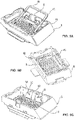
- FIG. 1A shows an apparatus for holding a tissue sample that is not part of the invention.
- a tissue cassette 1 retains a tissue sample 2 in the proper orientation to allow for the automation of the processing and a reduction in human error.
- a similar tissue cassette is disclosed in U.S. Patent Application No. 61/798,728 , title "Tissue Cassette with Biasing Element”.
- the tissue cassette 1 has a base 4 and a retractable retaining member 6 which cooperate to retain the tissue sample 2, as well as a retracting member 5 for retracting the retaining member 6, as discussed below.
- a frame 8 may optionally be provided to surround the outer perimeter of the retaining member 6 and attach to the retaining member with locking member 10. In this way, the retaining member 6 fits into the inside perimeter of the base 4, and the base 4, retaining member 6, and frame 8 are sealed by sealing member 12.
- the sealing member forms a liquid seal between the retaining member 6 and the base 4 to prevent liquid from leaking between the retaining member 6 and the base 4.
- Figure 1A further shows a base 4 with a bottom surface which corresponds to a second tissue engaging surface 14 and is configured to receive a tissue sample 2 in its desired orientation.
- the retaining member 6 Positioned over the base 4, the retaining member 6 is formed with a rim portion 16 and a retaining element 18 having a bottom surface corresponding to a first tissue engaging surface 20.
- an interior area 24 is defined between the base 4 and the retaining member 6 where the first tissue engaging surface 20 and the second tissue engaging surface 14 are facing each other.
- the retaining element 18 is attached to the rim portion 16 by a biasing element 22.
- the biasing element 22 urges the first tissue engaging surface 20 of the retaining element 18 downwardly away from the rim portion 16 and towards the second tissue engaging surface 14 of the base 4 to firmly hold the tissue sample 2 in the chosen orientation between the first and second tissue engaging surfaces 14, 20 such that it can later be embedded with paraffin or the like.
- a retracting member 5 is attached to the retaining member 6 to compress the biasing element 22 and retract the retaining element 18 upwardly away from the tissue sample 2.
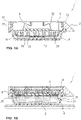
- paraffin 21 is added to the tissue cassette 1 to embed the tissue sample 2.
- the tissue cassette 1 is held against a chilling surface such that the paraffin at the bottom of the tissue cassette 1 starts to cool.
- a first, thin layer of solidified paraffin 23 adheres the tissue sample 2 to the base to partially secure the tissue sample 2 to the base 4.
- the retracting member 5 connected to the retaining member 6 pulls the first tissue engaging surface 20 of the retaining element 18 away from the tissue sample 2 and through the semi-molten paraffin such that the paraffin can contact the surface of the tissue sample 2.
- the retracting member 5 is a ferromagnetic member which responds when a magnetic field is introduced to compress the biasing element 22 and retract the first tissue engaging surface 20.
- the retracting member 5 allows the retaining member 18 to be separated from the embedded tissue sample for sectioning and analysis of the embedded tissue sample.
- the first tissue engaging surface 20 may be held in a position away from the tissue sample 2 until the remaining paraffin has solidified.
- the base 4 may be removed from the tissue cassette 1 to expose the embedded tissue sample and allow for sectioning of the embedded tissue sample (not shown).
- FIG. 2 shows an exploded view of the tissue cassette 1.
- the retaining member 6 has a rim 16, a biasing member 22 which connects the rim 16 to the retaining element 18, and a first tissue engaging surface 20 on the retaining element 18. Further, as shown in Figure 2 , a connector 19 may be provided to connect the first tissue engaging surface 20 to the biasing element 22.
- the rim 16 is provided with four walls and a substantially rectangular shape. On the inside of the rim 16 one end of the biasing member 22 is attached. The other end of the biasing member 22 attaches to the retaining element 18 at either a connector 19 or the first tissue engaging surface 20.
- the first tissue engaging surface 20 is provided with a substantially planar mesh portion 42.
- the mesh portion 42 is rectangular in shape, but the shape is not limiting and the mesh portion 42 can be a variety of shapes.
- the mesh portion 42 of the first tissue engaging surface 20 has a plurality of perforations 44 or cut-outs. When the mesh portion 42 is urged against the tissue sample 2 it holds the tissue sample 2 in place and allows reagents, or the like, to flow to the tissue sample 2 through the perforations 44 in the mesh portion 42.
- the perforations 44 are sized to allow the flow of fluid to the tissue sample 2 on the one hand, but to prevent the escape of the tissue sample 2 on the other hand.
- the perforations 44 in the mesh portion 42 may be sized according to the size of the tissue sample 2.
- the first tissue engaging surface 20 may alternatively be solid and have no holes on the surface while still allowing the agent to flow underneath the first tissue engaging surface 20 from the periphery.
- each biasing element 22 may in some embodiments is substantially hinged having an S or Z shape and attached at one end to the retaining element 18 and attach at the other end to the inner surface of the rim portion 16.
- the tissue cassette 1 has four biasing elements 22, where two biasing elements are shown in the Figure on one wall and the other two are on the opposite wall.
- the biasing element 22 urges the retaining element 18 towards the base 4 to fix the tissue sample 2 between the first and second tissue engaging surfaces 14, 20.
- the biasing element 22 can take on any shape that performs this function. For example, a torsion bar or a biasing element having another shape could also be used as discussed in more detail below.
- Each biasing element 22 has a first member 26 with a first end 27 and a second end 29. The first end 27 is connected to the retaining element 18. Extending downward at an angle from the hinge or second end 29 of the first member 26 is a first angled member 28. A second angled member 30 is connected to the first angled member 28 by a first curved hinged point 36. The second angled member 30 extends upwardly from the first angled member 28 at an angle; and in a non-limiting embodiment, the second angled member 30 and the first angled member 28 form an angle less than 90°. Extending downwardly from the second angled member 30 is a third angled member 32.
- the second angled member 30 and the third angled member 32 are connected by a second curved hinge point 38.
- the third angled member 32 and the second angled member 30 form an angle less than 90°.
- the third angled member 32 and the first angled member 28 form an angle less than 90°.
- a second member 34 connects to the third angled member 32 at a hinge point and extends substantially parallel to the retaining element 18. The second member 34 attaches to the rim portion 16 of the retaining member 6 in a non-limiting embodiment.
- the tissue cassette 1 has a base 4 which supports the tissue sample 2 and holds the paraffin for embedding.
- the base 4 has a generally rectangular shape with four side walls and a depressed bottom planar surface, referred to as the second tissue engaging surface 14.
- the base 4 is not limited to this shape and a different shape could be used without changing the scope of the invention.
- the base 4 is preferably solid so that it can hold the paraffin for embedding.
- the walls of the base 4 are preferably tapered inward to improve the ease at which the base can be removed from the paraffin after the embedding process.
- a frame 8 is placed around the outside perimeter of the retaining member 6 and functions to secure the retaining member 6 to the base 4.
- the frame 8 may also be used as a means for identifying the tissue sample.
- the frame 8 has a substantially rectangular shape with one end have an angled projection with an angled face 52.
- a label 54 may be placed on the angled face 52 to identify the tissue sample 2.
- the labels 54 are described in more detail below.
- the angle of the planar face is about 45 degrees, but the invention is not limited in this respect.
- frame 8 and the retaining member 6 are not easily removed so that once the tissue cassette 1 is used, the label 54 on the frame 8 will remain matched with the tissue sample 2 contained in the tissue cassette 1.
- frame 8 has a locking projections 12 which projects from the inside the perimeter of the frame 8, shown in Figure 1 .
- the locking projections 12 attach with an engaging portions 55 on the outer perimeter of the rim portion 16 on the retaining member 6 to secure the frame 8 to the retaining member 6.
- the base 4 includes a latching member 9 which acts as a clip or lock to hold the base 4 to the frame 8. Alternatively, if a frame 8 is not used, the latching member 9 can lock the base 4 to the retaining member 6.
- the latching member 9 is connected to a releasing member 60.
- the latching member 9 is flexibly attached to the base 4.
- the latching member 9 attaches to the clip surfaces 56 on the outer perimeter of the frame 8.
- the latching member 9 locks the base 4 to the frame 8 which is attached to the retaining member 6.
- a sealing member 10 connects the latching member 9 to the base 4 to form a seal between the surfaces on the perimeter of the base 4 and the frame 8 to sufficiently prevent paraffin from leaking during embedding.
- a gasket may be used as the sealing member 10 to help seal the base 4 and the frame 8.
- the latching member 9 is disengaged by pressing downward on the releasing member 60. When the releasing member 60 is pressed, the latching member 9 moves away from the base 4 and disengages from the clip surfaces 56.
- the sealing member 10 extends from the base 4, but the sealing member 10 may also extend from the retaining member 6 or the frame 8.
- the tissue cassette 1 includes a label 54 or ID tag as shown in Figure 2 .
- the label can 54 be located anywhere on the tissue cassette 1, but is preferably located on the frame 8. More than one tag may be present. When more than one tag is present, the tags can be physically separated or located together.
- the label 54 may be a computer or human readable tag including, but not limited to, labels having an incorporated RFID, labels having an incorporated one-dimensional barcode (1-D barcode), labels having an incorporated two-dimensional barcode (2-D barcode), and labels having an incorporated three-dimensional barcode (3-D barcode).
- the computer readable label is not limited to RFID, 1-D barcode, 2-D barcode, or 3-D barcode labels and may include any type of label readable by a computer as would be apparent to a person of ordinary skill in the art.
- a label 54 can be present that may be sensitive to changes to the sample or itself.
- a label 54 may be present that changes physical (i.e. color) or chemical (i.e. redox, conjugation, etc.) properties during fixation of the sample.
- a label 54 may be present that is sensitive to the processing steps which precede embedding (i.e. dehydration).
- a label 54 may be present that is sensitive to the embedding step (i.e. infiltration of paraffin).
- the label 54 may have a property that changes incrementally or switches when the step is complete. In this way, the technician, or an automated system, will be able to determine when the sample has finished one step before another is started.
- the tissue cassette 1 can be made from various materials and the same or different materials can be used for the retaining member 6, including the retaining element 18, the first tissue engaging surface 20, the mesh portion 42, and the base 4.
- materials used include: an acetal copolymer, Teflon, polypropylene, and stainless steel.
- the acetal copolymer is DELRIN 900.
- the base 4 is made out of a polypropylene material so that the base 4 does not attach to the paraffin after the tissue sample 2 is embedded.
- the tissue cassette including the base, the retaining member, and/or the frame, may be produced from a material lacking any dye or coloring. The lack of color may allow the technician to view the tissue sample in the tissue cassette and ensure that the tissue sample has remained in its desired orientation after embedding.
- the tissue cassette, including the base, the retaining member, and/or the frame may be at least at least opaque or clear.
- retracting member 5 is disposed on the retaining member 6 for compressing the biasing element 22 and retracting the retaining element 18 from the tissue sample 2.
- the retracting member 5 retracts the first tissue engaging surface 20 of the retaining element 18 from the tissue sample 2 and can take on any form or shape that serves this function.
- the retracting member 5 may be provided as a ferromagnetic member 47.
- the ferromagnetic member 47 is connected to the retaining element 18 and in certain non-limiting embodiments is insert molded to the first tissue engaging surface 20.
- the ferromagnetic member 47 may be divided into smaller components and incorporated in the mesh structure 42 of the first tissue engaging surface 20.
- Figure 4A illustrates that after the tissue cassette 1 has been filled with paraffin 21 and placed on a chilling surface, a magnetic field is introduced by a magnetic instrument 41.
- the magnetic instrument 41 is introduced approximately 30 seconds after the paraffin has been placed in the tissue cassette 1.
- the introduction time is paraffin grade dependent and not limiting to this invention.
- the magnetic field can be introduced either by permanent magnets being moved closer to the tissue cassette, electromagnets being powered up, some combination of the both, or any other example obvious to one of ordinary skill in the art.
- the magnetic field introduced by the magnetic instrument 41 attracts the ferromagnetic member 47 and moves the first tissue engaging surface upwardly to compress the biasing element 22.
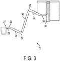
- the first tissue engaging surface 20 will stop retracting once it contacts a dead stop 40 (as shown in Figure 3 ).
- the dead stop 40 may be provided on the biasing element 22, the frame 8, or the retaining member 6.
- a gap 45 will be formed between the tissue sample 2 and the first tissue engaging surface 20 so that the paraffin completely covers the upper surface of the tissue sample, as shown in Figure 4B .
- the base will have flow channels such that the paraffin may cover the bottom surface of the tissue sample. The magnetic force is maintained until the paraffin solidifies enough such that the mesh will not fall back through the paraffin once the magnetic force stops.
- Figures 5-7 illustrate embodiments that are not part of the invention where the retracting member 5 comprises a mechanical member, such as a lever, a tab, or contact point. All other aspects of these embodiments have the same features of the embodiments described above.
- a lever 48 is provided on the retaining member 6 and is attached to the retaining element 18. A portion of the lever 48 hangs over the edge of the frame 8 such that a mechanism driven from above can push down on the overhanging portion 49 of the lever 48 and cause the retaining element 18 to move up, away from the tissue sample 2 (not shown).
- Figure 5B shows an alternate embodiment that is not part of the invention where the lever 48 provided does not hang over the side of the frame 8.
- the lever 48 can be pulled upward by an external tool 57 (not shown) to cause the retaining element 18 to move away from the tissue sample 2.
- Figure 5B illustrates the lever in a retained/non-retracted state.
- tabs 50 are provided on the biasing element 22.
- the tabs 50 are connected to the retaining member 6 or biasing element 22 and are provided substantially in the center of the two biasing elements 22 to hang over the outer surface of the frame 8.
- the tabs 50 may be flush with the side of frame 8 and the frame 8 may be indented as shown in Figure 5C to allow for the tabs 50 to be pushed or pulled by a tool 57 which contacts the exterior portion of the tabs.
- the tabs 50 may be pulled or pushed upward such that the retaining element 18 moves away from the tissue sample and the biasing element 22 is compressed.
- FIG. 5C shows one tab 50 on each side of the tissue cassette 1
- more than one tab may be provided and may be located anywhere on the retaining member 6 or biasing element 22.
- two tabs 50 may extend from each second curved hinge point 38 of the biasing element 18.
- a tool 57 could be provided to contact underneath the second curved hinge point 38 of each biasing member and pull up on the second curved hinge point 38 to contract the biasing element 22.
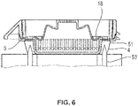
- Figure 6 is an interior side view of a tissue cassette that is not part of the invention in an assembled state.
- the retracting member 5 is disposed on the edge of the retaining element 18.
- the base 4 has locally weak areas 51 such that pins 53 pierce the locally weak areas 51 in the base 4. The pins 53 push through the base 4 and contact the retracting member 5 on the retaining element 18 to push through and lift up the retaining element 18.
- Figure 7 is a cut-out of a tissue cassette that is not part of the invention in an assembled state.
- a biasing element 22 is provided with a plurality of torsion tabs 61.
- the torsion tabs 61 extend along an upper surface of the biasing element 22 to connect the two biasing elements. As such, when a tool 57 presses down on the center of the torsion tab 61, the torsion tabs 61, being connected to each biasing element 22, deflect upwardly on an outer portion of the biasing element. This pressure to the torsion tabs 61 compresses the biasing elements 22 such that the retaining element 18 is pulled up and away from the tissue sample 2.
- the torsion tab examples include: an acetal copolymer, Teflon, polypropylene, and stainless steel.
- the acetal copolymer is DELRIN 900.
- the torsion tab may be molded integral with the tissue cassette 1.
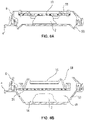
- FIGs 8A and 8B show an example of an embodiment according to the present invention in which the retaining element 18 is flexibly attached to the base 4 and the retaining member 6.
- biasing members 58 are attached to the retaining member 6 and the base 4.
- paraffin 21 (not shown) may be added to the tissue cassette 1 to secure the tissue sample 2 to the base 4.
- Figure 8A shows an unreleased condition.
- the biasing members 58 on the base 4 may be released to move the base 4 away from the tissue sample 2 as shown in Figure 8B in the released condition.
- the tissue sample 2 is provided on the base and a gap 45 is provided between the first tissue engaging surface 20 and the second tissue engaging surface 14.
- the tissue sample container 1 is stable when either the biasing member 58 attached to the retaining member 6 or biasing member 58 attached to the base 4 is applying a biasing force, or when both are applying or not a biasing force.
- the biasing member 58 on the base 4 may be used only to enable the releasing of the force that is applied by the biasing member 58 on retaining member 6.
- the tissue cassette 1 provides a two position floor. The first position is when the biasing member 58 on the base 4 compresses the second tissue engaging surface 14 upwardly such that the tissue engaging surface is compressed up towards the retaining member 6 to compress the tissue sample 2. The second position is when the force of the biasing member 58 on the base is released so that the second tissue engaging surface 14 is moves downwardly.
- the second tissue engaging surface 14 retracts away from the tissue 2, such that the floor of the base retracts, similar to the first tissue engaging surface 20 of the previous embodiments retracting towards and away from the tissue sample 2.
- the embodiment shown in Figures 8A and 8B has the same configuration and tracks the same structure as discussed above.
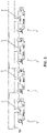
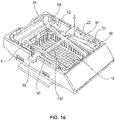
- Figure 9 shows an embodiment which is not part of the invention and in which a plurality of tissue cassettes are provided and a single plate 59 is used to retract the retaining members 18 of the tissue cassettes at the same time.
- Figure 10 illustrates a design that is not part of the invention for the biasing elements 22 as well as a related alternative design for the retracting member.
- a similar biasing element design is discussed in a related application U.S. Patent Application No. 61/798,728 , title "Tissue Cassette with Biasing Element" referenced above.
- the biasing element 22 includes two angled members 82, 90.
- One end of the first angled member 82 is fixed to the retaining member 6 at a fixed point 84 and angles downward from the fixed point 84.
- the opposite end of the first angled member 82 attaches to the retaining element 18 at a first moving point 86.
- One end of the second angled member 90 is slidably received in a notch 92 of the retaining member 6 in a direction parallel to the second tissue engaging surface 14.
- the opposite end of the second angled member 90 is attached to the retaining element 18 at a second moving point 94.
- the first angled member 82 and the second angled member 90 are angled such that the members cross substantially in the center of each member at a hinge point 96 where they are connected to a cross member 100, as shown in Figure 10 .
- the biasing element 22 shown in Figure 10 can be retracted by a retracting member 5, such as tabs 50 connected to the cross member 100.
- a retracting member 5 such as tabs 50 connected to the cross member 100.
- tabs 50 extend out from the biasing element 22 and hang over the frame.
- the tabs 50 can be pulled or pushed in an upwardly direction to compress the biasing element 22 and retract the retaining element 18.
- the tabs 50 can be placed anywhere on the retaining member 6 connected to the retaining element 18, similar to the embodiment described with respect to Figure 5C .
- a tool 57 could be provided to rotate the second angled member to slide along the notch 92 to retract the retaining element 18.
- the retracting member 5 may be formed from a shaped memory polymer.
- the shape memory polymer deforms and retracts the retaining element 18 when exposed to a thermal change, such as an increase or decrease in temperature.
- the retracting member 5 may be part of the biasing member 22 and the biasing member 22 may be a shaped memory polymer such that the biasing element 22 deforms and compresses when exposed to a first external stimulus, for example, a thermal change, and return to their original (permanent) shape when exposed to a second external stimulus, such as a further thermal change.
- the shape memory polymer may deform when exposed to radiation, such as electromagnetic radiation, infrared radiation, or ultraviolet radiation.
- radiation such as electromagnetic radiation, infrared radiation, or ultraviolet radiation.
- shape memory polymers include linear block copolymers and other thermoplastic copolymers but may include metallic alloys, ceramics and gels.
Landscapes
- Health & Medical Sciences (AREA)
- Chemical & Material Sciences (AREA)
- Life Sciences & Earth Sciences (AREA)
- General Health & Medical Sciences (AREA)
- Analytical Chemistry (AREA)
- Immunology (AREA)
- Biochemistry (AREA)
- General Physics & Mathematics (AREA)
- Physics & Mathematics (AREA)
- Pathology (AREA)
- Engineering & Computer Science (AREA)
- Biomedical Technology (AREA)
- Molecular Biology (AREA)
- Hematology (AREA)
- Clinical Laboratory Science (AREA)
- Chemical Kinetics & Catalysis (AREA)
- Sampling And Sample Adjustment (AREA)
- Surgical Instruments (AREA)
Description
- The present invention relates generally to a tissue cassette for retaining a tissue sample.
- After a tissue sample is collected, the tissue sample is analyzed at a lab (e.g. a pathology lab, biomedical lab, etc.) that is set up to perform the appropriate tests (such as histological analysis). In order to properly process the tissue sample a series of steps may be performed including:
- 1. Grossing of the sample by cutting the sample to the proper size for analysis.
- 2. Fixing of the sample to immobilize molecular components and/or prevent degradation.
- 3. Embedding the sample in an embedding material, such as paraffin wax
- 4. Sectioning the embedded sample by using, for example, a microtome.
- In conventional methods, the grossing step involves a lab technician cutting the tissue to the appropriate size for analysis and then placing the tissue in a tissue cassette. During the fixation stage, the cassettes are generally exposed to a fixing agent or chemical (e.g., a solution of formaldehyde in water such as formalin) shortly after sample collection. For example,
U.S. Patent No. 7,156, 814 discloses a cassette which can withstand tissue preparation procedures. - After the tissue sample has been processed, the medical professional, in conventional methods, removes the tissue sample from the individual cassette to perform the embedding step. Specifically, the medical professional carefully orients the sample, based on the diagnostic view required, into a base mold containing an embedding material such as paraffin wax. Once the tissue is oriented properly in the base mold, the molten material is cooled to fully embed the tissue sample and hold it in the proper orientation. The paraffin is used to hold the sample in position while also providing a uniform consistency to further facilitate sectioning. While the term paraffin is used, this term is not limiting and describes an example of an embedding medium. Further, the term sample is not limiting and can refer to one or more tissue samples.
- After the sample is embedding in paraffin, the embedded paraffin is sliced into a plurality of thin sections (e.g., 2 to 25 µ thick sections), often using a microtome, for further processing and inspection. Such sectioning of the sample often helps a medical professional properly assess the sample under a microscope (e.g. diagnose relationships between cells and other constituents of the sample, or perform other assessments).
- The current process requires human intervention at both the grossing and embedding steps. Such manual handling of the sample can increase the likelihood of mis-identifying the sample, cross contaminating the samples, or losing part of the sample or the entire sample. Additionally, the numerous steps of manual manipulation can often increase the time that it takes to provide a proper assessment for each sample, once the sample is collected.
-
US 4,801,553 A discloses a cassette for holding a tissue specimen. The cassette comprises a body portion and a separable portion which snap together to enclose a sample in a mould space of the cassette. -
US 2008/138854 A1 discloses a histologic tissue sample support device comprising a tissue support for receiving the sample. Further, a resilient cellular material is coupled to the tissue support and is configured to engage and retain tissue in place during processing. -
US 2010/184127 A1 discloses a tissue orientation device including a perforated tissue support with a perforated channel for receiving a sample. The device further comprises tabs configured to extend along and into the channel to retain the tissue sample during processing and embedding. - In view of the foregoing, the present invention provides an apparatus according to
claim 1 to allow for reduced manual manipulation of a tissue sample after it is oriented and placed in a tissue cassette and also to maintain the identity of the tissue sample. -
-
Figure 1A is an interior side view of an assembled tissue cassette that is not part of the invention with the retaining element in a non-retracted state; -
Figure 1B an interior side view of the tissue cassette ofFigure 1A with the retaining element in a retracted state; -
Figure 2 is an exploded view of the tissue cassette in a non-assembled state. -
Figure 3 shows a cut-out section of the biasing element on the tissue cassette. -
Figures 4A and 4B illustrate the tissue cassette according that is not part of the invention where the retracting member is a magnetic member -
Figures 5A-5C illustrate tissue cassettes that are not part of the invention where the retracting member is mechanical member. -
Figure 6 is an interior side view of a tissue cassette that is not part of the invention in an assembled state. -
Figure 7 is a cut-out of a tissue cassette that is not part of the invention in an assembled state. -
Figures 8A and 8B are interior side views of an example of a tissue cassette according to the present invention in an assembled state. -
Figure 9 illustrates a plurality of tissue retaining members and retracting members that are not part of the invention. -
Figure 10 illustrates the tissue cassette that is not part of the invention in an assembled state. -
Figure 1A shows an apparatus for holding a tissue sample that is not part of the invention. As shown, atissue cassette 1 retains atissue sample 2 in the proper orientation to allow for the automation of the processing and a reduction in human error. A similar tissue cassette is disclosed inU.S. Patent Application No. 61/798,728 - The
tissue cassette 1 has abase 4 and aretractable retaining member 6 which cooperate to retain thetissue sample 2, as well as a retractingmember 5 for retracting the retainingmember 6, as discussed below. In addition, aframe 8 may optionally be provided to surround the outer perimeter of the retainingmember 6 and attach to the retaining member withlocking member 10. In this way, the retainingmember 6 fits into the inside perimeter of thebase 4, and thebase 4, retainingmember 6, andframe 8 are sealed by sealingmember 12. The sealing member forms a liquid seal between the retainingmember 6 and thebase 4 to prevent liquid from leaking between the retainingmember 6 and thebase 4. -
Figure 1A further shows abase 4 with a bottom surface which corresponds to a secondtissue engaging surface 14 and is configured to receive atissue sample 2 in its desired orientation. Positioned over thebase 4, theretaining member 6 is formed with arim portion 16 and aretaining element 18 having a bottom surface corresponding to a firsttissue engaging surface 20. Generally, when thebase 4 and theretaining member 6 are engaged as shown inFigure 1A , aninterior area 24 is defined between thebase 4 and the retainingmember 6 where the firsttissue engaging surface 20 and the secondtissue engaging surface 14 are facing each other. - The
retaining element 18 is attached to therim portion 16 by abiasing element 22. Upon engagement of the retainingmember 6 to thebase 4, thebiasing element 22 urges the firsttissue engaging surface 20 of theretaining element 18 downwardly away from therim portion 16 and towards the secondtissue engaging surface 14 of thebase 4 to firmly hold thetissue sample 2 in the chosen orientation between the first and secondtissue engaging surfaces member 5 is attached to the retainingmember 6 to compress thebiasing element 22 and retract the retainingelement 18 upwardly away from thetissue sample 2. - As shown in
Figure 1B ,paraffin 21 is added to thetissue cassette 1 to embed thetissue sample 2. After theparaffin 21 has been added to thetissue cassette 1, thetissue cassette 1 is held against a chilling surface such that the paraffin at the bottom of thetissue cassette 1 starts to cool. When the paraffin starts to cool, a first, thin layer ofsolidified paraffin 23 adheres thetissue sample 2 to the base to partially secure thetissue sample 2 to thebase 4. As discussed in greater detail below, while theparaffin 21 is still molten, the retractingmember 5 connected to the retainingmember 6 pulls the firsttissue engaging surface 20 of theretaining element 18 away from thetissue sample 2 and through the semi-molten paraffin such that the paraffin can contact the surface of thetissue sample 2. According to this embodiment the retractingmember 5 is a ferromagnetic member which responds when a magnetic field is introduced to compress thebiasing element 22 and retract the firsttissue engaging surface 20. As discussed below with reference toFigures 4A-4B , the retractingmember 5 allows the retainingmember 18 to be separated from the embedded tissue sample for sectioning and analysis of the embedded tissue sample. As such, the firsttissue engaging surface 20 may be held in a position away from thetissue sample 2 until the remaining paraffin has solidified. Once theparaffin 21 has solidified, thebase 4 may be removed from thetissue cassette 1 to expose the embedded tissue sample and allow for sectioning of the embedded tissue sample (not shown). - The individual components of the tissue cassette, including the retracting member, will now be described in more detail.
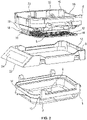
Figure 2 shows an exploded view of thetissue cassette 1. The retainingmember 6 has arim 16, a biasingmember 22 which connects therim 16 to the retainingelement 18, and a firsttissue engaging surface 20 on the retainingelement 18. Further, as shown inFigure 2 , aconnector 19 may be provided to connect the firsttissue engaging surface 20 to the biasingelement 22. - The
rim 16 is provided with four walls and a substantially rectangular shape. On the inside of therim 16 one end of the biasingmember 22 is attached. The other end of the biasingmember 22 attaches to the retainingelement 18 at either aconnector 19 or the firsttissue engaging surface 20. - As shown in
Figure 2 , the firsttissue engaging surface 20 is provided with a substantiallyplanar mesh portion 42. In this embodiment themesh portion 42 is rectangular in shape, but the shape is not limiting and themesh portion 42 can be a variety of shapes. Themesh portion 42 of the firsttissue engaging surface 20 has a plurality ofperforations 44 or cut-outs. When themesh portion 42 is urged against thetissue sample 2 it holds thetissue sample 2 in place and allows reagents, or the like, to flow to thetissue sample 2 through theperforations 44 in themesh portion 42. Theperforations 44 are sized to allow the flow of fluid to thetissue sample 2 on the one hand, but to prevent the escape of thetissue sample 2 on the other hand. Thus, theperforations 44 in themesh portion 42 may be sized according to the size of thetissue sample 2. Further, the firsttissue engaging surface 20, may alternatively be solid and have no holes on the surface while still allowing the agent to flow underneath the firsttissue engaging surface 20 from the periphery. - As shown in
Figure 3 , each biasingelement 22 may in some embodiments is substantially hinged having an S or Z shape and attached at one end to the retainingelement 18 and attach at the other end to the inner surface of therim portion 16. In the illustrated embodiment inFigure 2 , thetissue cassette 1 has four biasingelements 22, where two biasing elements are shown in the Figure on one wall and the other two are on the opposite wall. The biasingelement 22 urges the retainingelement 18 towards thebase 4 to fix thetissue sample 2 between the first and secondtissue engaging surfaces element 22 can take on any shape that performs this function. For example, a torsion bar or a biasing element having another shape could also be used as discussed in more detail below. - The biasing
element 22 is shown inFigure 3 . Each biasingelement 22 has afirst member 26 with afirst end 27 and asecond end 29. Thefirst end 27 is connected to the retainingelement 18. Extending downward at an angle from the hinge orsecond end 29 of thefirst member 26 is a firstangled member 28. A secondangled member 30 is connected to the firstangled member 28 by a first curved hingedpoint 36. The secondangled member 30 extends upwardly from the firstangled member 28 at an angle; and in a non-limiting embodiment, the secondangled member 30 and the firstangled member 28 form an angle less than 90°. Extending downwardly from the secondangled member 30 is a thirdangled member 32. The secondangled member 30 and the thirdangled member 32 are connected by a secondcurved hinge point 38. In a non-limiting embodiment, the thirdangled member 32 and the secondangled member 30 form an angle less than 90°. Further, in a non-limiting embodiment, the thirdangled member 32 and the firstangled member 28 form an angle less than 90°. Asecond member 34 connects to the thirdangled member 32 at a hinge point and extends substantially parallel to the retainingelement 18. Thesecond member 34 attaches to therim portion 16 of the retainingmember 6 in a non-limiting embodiment. - The
base 4 will now be described with reference toFigure 2 . As discussed above, thetissue cassette 1 has abase 4 which supports thetissue sample 2 and holds the paraffin for embedding. Thebase 4 has a generally rectangular shape with four side walls and a depressed bottom planar surface, referred to as the secondtissue engaging surface 14. Thebase 4 is not limited to this shape and a different shape could be used without changing the scope of the invention. Thebase 4 is preferably solid so that it can hold the paraffin for embedding. The walls of thebase 4 are preferably tapered inward to improve the ease at which the base can be removed from the paraffin after the embedding process. - As noted above, in some embodiments a
frame 8 is placed around the outside perimeter of the retainingmember 6 and functions to secure the retainingmember 6 to thebase 4. Theframe 8 may also be used as a means for identifying the tissue sample. As shown in inFigure 2 , theframe 8 has a substantially rectangular shape with one end have an angled projection with anangled face 52. As shown inFigure 2 , alabel 54 may be placed on theangled face 52 to identify thetissue sample 2. Thelabels 54 are described in more detail below. In this embodiment, the angle of the planar face is about 45 degrees, but the invention is not limited in this respect. - The
frame 8 and the retainingmember 6 are not easily removed so that once thetissue cassette 1 is used, thelabel 54 on theframe 8 will remain matched with thetissue sample 2 contained in thetissue cassette 1. In certain embodiments,frame 8 has a lockingprojections 12 which projects from the inside the perimeter of theframe 8, shown inFigure 1 . The lockingprojections 12 attach with an engagingportions 55 on the outer perimeter of therim portion 16 on the retainingmember 6 to secure theframe 8 to the retainingmember 6. Once theframe 8 is connected to thebase 4 using this locking arrangement, it is difficult to separate them. - The
base 4 includes a latchingmember 9 which acts as a clip or lock to hold thebase 4 to theframe 8. Alternatively, if aframe 8 is not used, the latchingmember 9 can lock thebase 4 to the retainingmember 6. - As shown in
Figure 2 , the latchingmember 9 is connected to a releasing member 60. The latchingmember 9 is flexibly attached to thebase 4. When the latchingmember 9 is engaged, the latchingmember 9 attaches to the clip surfaces 56 on the outer perimeter of theframe 8. The latchingmember 9 locks thebase 4 to theframe 8 which is attached to the retainingmember 6. In this way, a sealingmember 10 connects the latchingmember 9 to thebase 4 to form a seal between the surfaces on the perimeter of thebase 4 and theframe 8 to sufficiently prevent paraffin from leaking during embedding. A gasket may be used as the sealingmember 10 to help seal thebase 4 and theframe 8. The latchingmember 9 is disengaged by pressing downward on the releasing member 60. When the releasing member 60 is pressed, the latchingmember 9 moves away from thebase 4 and disengages from the clip surfaces 56. The sealingmember 10 extends from thebase 4, but the sealingmember 10 may also extend from the retainingmember 6 or theframe 8. - An important aspect of tissue sample analysis is properly keeping track of tissue samples. In some embodiments, the
tissue cassette 1 includes alabel 54 or ID tag as shown inFigure 2 . The label can 54 be located anywhere on thetissue cassette 1, but is preferably located on theframe 8. More than one tag may be present. When more than one tag is present, the tags can be physically separated or located together. - The
label 54 may be a computer or human readable tag including, but not limited to, labels having an incorporated RFID, labels having an incorporated one-dimensional barcode (1-D barcode), labels having an incorporated two-dimensional barcode (2-D barcode), and labels having an incorporated three-dimensional barcode (3-D barcode). However, the computer readable label is not limited to RFID, 1-D barcode, 2-D barcode, or 3-D barcode labels and may include any type of label readable by a computer as would be apparent to a person of ordinary skill in the art. - A
label 54 can be present that may be sensitive to changes to the sample or itself. Alabel 54 may be present that changes physical (i.e. color) or chemical (i.e. redox, conjugation, etc.) properties during fixation of the sample. Similarly, alabel 54 may be present that is sensitive to the processing steps which precede embedding (i.e. dehydration). Alternatively, alabel 54 may be present that is sensitive to the embedding step (i.e. infiltration of paraffin). Thelabel 54 may have a property that changes incrementally or switches when the step is complete. In this way, the technician, or an automated system, will be able to determine when the sample has finished one step before another is started. - The
tissue cassette 1 can be made from various materials and the same or different materials can be used for the retainingmember 6, including the retainingelement 18, the firsttissue engaging surface 20, themesh portion 42, and thebase 4. Examples of materials used include: an acetal copolymer, Teflon, polypropylene, and stainless steel. In a non-limiting embodiment, the acetal copolymer is DELRIN 900. In a non-limiting embodiment, thebase 4 is made out of a polypropylene material so that thebase 4 does not attach to the paraffin after thetissue sample 2 is embedded. - The tissue cassette, including the base, the retaining member, and/or the frame, may be produced from a material lacking any dye or coloring. The lack of color may allow the technician to view the tissue sample in the tissue cassette and ensure that the tissue sample has remained in its desired orientation after embedding. In these embodiments, the tissue cassette, including the base, the retaining member, and/or the frame may be at least at least opaque or clear.
- Some examples of retracting
member 5 will now be described in additional detail. As previously stated and shown with respect toFigures 1A and 1B , the retractingmember 5 is disposed on the retainingmember 6 for compressing the biasingelement 22 and retracting the retainingelement 18 from thetissue sample 2. The retractingmember 5 retracts the firsttissue engaging surface 20 of the retainingelement 18 from thetissue sample 2 and can take on any form or shape that serves this function. - As shown in
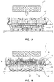
Figures 4A and 4B , the retractingmember 5 may be provided as aferromagnetic member 47. Theferromagnetic member 47 is connected to the retainingelement 18 and in certain non-limiting embodiments is insert molded to the firsttissue engaging surface 20. Alternatively, theferromagnetic member 47 may be divided into smaller components and incorporated in themesh structure 42 of the firsttissue engaging surface 20. -
Figure 4A illustrates that after thetissue cassette 1 has been filled withparaffin 21 and placed on a chilling surface, a magnetic field is introduced by amagnetic instrument 41. By way of example, themagnetic instrument 41 is introduced approximately 30 seconds after the paraffin has been placed in thetissue cassette 1. The introduction time is paraffin grade dependent and not limiting to this invention. The magnetic field can be introduced either by permanent magnets being moved closer to the tissue cassette, electromagnets being powered up, some combination of the both, or any other example obvious to one of ordinary skill in the art. - The magnetic field introduced by the
magnetic instrument 41 attracts theferromagnetic member 47 and moves the first tissue engaging surface upwardly to compress the biasingelement 22. The firsttissue engaging surface 20 will stop retracting once it contacts a dead stop 40 (as shown inFigure 3 ). Thedead stop 40 may be provided on the biasingelement 22, theframe 8, or the retainingmember 6. Thus, agap 45 will be formed between thetissue sample 2 and the firsttissue engaging surface 20 so that the paraffin completely covers the upper surface of the tissue sample, as shown inFigure 4B . Further, in certain non-limiting embodiments, the base will have flow channels such that the paraffin may cover the bottom surface of the tissue sample. The magnetic force is maintained until the paraffin solidifies enough such that the mesh will not fall back through the paraffin once the magnetic force stops. -
Figures 5-7 illustrate embodiments that are not part of the invention where the retractingmember 5 comprises a mechanical member, such as a lever, a tab, or contact point. All other aspects of these embodiments have the same features of the embodiments described above. - In the embodiment shown in
Figure 5A that is not part of the invention, alever 48 is provided on the retainingmember 6 and is attached to the retainingelement 18. A portion of thelever 48 hangs over the edge of theframe 8 such that a mechanism driven from above can push down on the overhangingportion 49 of thelever 48 and cause the retainingelement 18 to move up, away from the tissue sample 2 (not shown). -
Figure 5B shows an alternate embodiment that is not part of the invention where thelever 48 provided does not hang over the side of theframe 8. In this example thelever 48 can be pulled upward by an external tool 57 (not shown) to cause the retainingelement 18 to move away from thetissue sample 2.Figure 5B illustrates the lever in a retained/non-retracted state. - In the embodiment that is not part of the invention shown in
Figure 5C ,tabs 50 are provided on the biasingelement 22. Thetabs 50 are connected to the retainingmember 6 or biasingelement 22 and are provided substantially in the center of the two biasingelements 22 to hang over the outer surface of theframe 8. Thetabs 50 may be flush with the side offrame 8 and theframe 8 may be indented as shown inFigure 5C to allow for thetabs 50 to be pushed or pulled by atool 57 which contacts the exterior portion of the tabs. Thetabs 50 may be pulled or pushed upward such that the retainingelement 18 moves away from the tissue sample and the biasingelement 22 is compressed. WhileFigure 5C shows onetab 50 on each side of thetissue cassette 1, more than one tab may be provided and may be located anywhere on the retainingmember 6 or biasingelement 22. For example, twotabs 50 may extend from each secondcurved hinge point 38 of the biasingelement 18. Alternatively, atool 57 could be provided to contact underneath the secondcurved hinge point 38 of each biasing member and pull up on the secondcurved hinge point 38 to contract the biasingelement 22. -
Figure 6 is an interior side view of a tissue cassette that is not part of the invention in an assembled state. In this instance the retractingmember 5 is disposed on the edge of the retainingelement 18. Further, thebase 4 has locallyweak areas 51 such that pins 53 pierce the locallyweak areas 51 in thebase 4. Thepins 53 push through thebase 4 and contact the retractingmember 5 on the retainingelement 18 to push through and lift up the retainingelement 18. -
Figure 7 is a cut-out of a tissue cassette that is not part of the invention in an assembled state. A biasingelement 22 is provided with a plurality oftorsion tabs 61. Thetorsion tabs 61 extend along an upper surface of the biasingelement 22 to connect the two biasing elements. As such, when atool 57 presses down on the center of thetorsion tab 61, thetorsion tabs 61, being connected to each biasingelement 22, deflect upwardly on an outer portion of the biasing element. This pressure to thetorsion tabs 61 compresses the biasingelements 22 such that the retainingelement 18 is pulled up and away from thetissue sample 2. Examples of materials used for the torsion tab include: an acetal copolymer, Teflon, polypropylene, and stainless steel. In a non-limiting embodiment, the acetal copolymer is DELRIN 900. In some embodiments, the torsion tab may be molded integral with thetissue cassette 1. -
Figures 8A and 8B show an example of an embodiment according to the present invention in which the retainingelement 18 is flexibly attached to thebase 4 and the retainingmember 6. In thisexample biasing members 58 are attached to the retainingmember 6 and thebase 4. Thus, in this instance, paraffin 21 (not shown) may be added to thetissue cassette 1 to secure thetissue sample 2 to thebase 4.Figure 8A shows an unreleased condition. Then the biasingmembers 58 on thebase 4 may be released to move thebase 4 away from thetissue sample 2 as shown inFigure 8B in the released condition. Thus, when thebase 4 is released, thetissue sample 2 is provided on the base and agap 45 is provided between the firsttissue engaging surface 20 and the secondtissue engaging surface 14. Accordingly, paraffin may fill thegap 45 and embed thetissue sample 2. In this embodiment, thetissue sample container 1 is stable when either the biasingmember 58 attached to the retainingmember 6 or biasingmember 58 attached to thebase 4 is applying a biasing force, or when both are applying or not a biasing force. - For example, in this non-limiting embodiment, the biasing
member 58 on thebase 4 may be used only to enable the releasing of the force that is applied by the biasingmember 58 on retainingmember 6. As an example, in this embodiment, thetissue cassette 1 provides a two position floor. The first position is when the biasingmember 58 on thebase 4 compresses the secondtissue engaging surface 14 upwardly such that the tissue engaging surface is compressed up towards the retainingmember 6 to compress thetissue sample 2. The second position is when the force of the biasingmember 58 on the base is released so that the secondtissue engaging surface 14 is moves downwardly. In this way, the secondtissue engaging surface 14 retracts away from thetissue 2, such that the floor of the base retracts, similar to the firsttissue engaging surface 20 of the previous embodiments retracting towards and away from thetissue sample 2. Other than these differences noted, the embodiment shown inFigures 8A and 8B has the same configuration and tracks the same structure as discussed above. -
Figure 9 shows an embodiment which is not part of the invention and in which a plurality of tissue cassettes are provided and asingle plate 59 is used to retract the retainingmembers 18 of the tissue cassettes at the same time. -
Figure 10 illustrates a design that is not part of the invention for the biasingelements 22 as well as a related alternative design for the retracting member. A similar biasing element design is discussed in a relatedapplication U.S. Patent Application No. 61/798,728 - As shown in
Figure 10 , the biasingelement 22 includes twoangled members angled member 82 is fixed to the retainingmember 6 at a fixedpoint 84 and angles downward from the fixedpoint 84. The opposite end of the firstangled member 82 attaches to the retainingelement 18 at a first movingpoint 86. One end of the secondangled member 90 is slidably received in anotch 92 of the retainingmember 6 in a direction parallel to the secondtissue engaging surface 14. The opposite end of the secondangled member 90 is attached to the retainingelement 18 at a second movingpoint 94. The firstangled member 82 and the secondangled member 90 are angled such that the members cross substantially in the center of each member at ahinge point 96 where they are connected to across member 100, as shown inFigure 10 . - Similar to the example of the biasing
element 22 described above the biasingelement 22 shown inFigure 10 can be retracted by a retractingmember 5, such astabs 50 connected to thecross member 100. As shown inFigure 10 ,tabs 50 extend out from the biasingelement 22 and hang over the frame. Thus, thetabs 50 can be pulled or pushed in an upwardly direction to compress the biasingelement 22 and retract the retainingelement 18. Thetabs 50 can be placed anywhere on the retainingmember 6 connected to the retainingelement 18, similar to the embodiment described with respect toFigure 5C . - Alternatively, a
tool 57 could be provided to rotate the second angled member to slide along thenotch 92 to retract the retainingelement 18. - In another exemplary embodiment of the
tissue cassette 1 that is not part of the invention, the retractingmember 5 may be formed from a shaped memory polymer. In certain examples of this embodiment, the shape memory polymer deforms and retracts the retainingelement 18 when exposed to a thermal change, such as an increase or decrease in temperature. For example, the retractingmember 5 may be part of the biasingmember 22 and the biasingmember 22 may be a shaped memory polymer such that the biasingelement 22 deforms and compresses when exposed to a first external stimulus, for example, a thermal change, and return to their original (permanent) shape when exposed to a second external stimulus, such as a further thermal change. In other exemplary embodiments, the shape memory polymer may deform when exposed to radiation, such as electromagnetic radiation, infrared radiation, or ultraviolet radiation. Non-limiting examples of shape memory polymers include linear block copolymers and other thermoplastic copolymers but may include metallic alloys, ceramics and gels. - The previous description of the non-limiting embodiments is provided to enable one skilled in the art to make and use the present invention. Moreover, various modifications to these embodiments will be readily apparent to those skilled in the art, and the generic principles and specific examples defined herein may be applied to other embodiments without the use of inventive faculty. Therefore, the present invention is not intended to be limited to the embodiments described herein, but is to be accorded the widest possible scope as defined by the recitations of the claims.
Claims (3)
- An apparatus for holding a tissue sample (2), comprising:a retaining member (6);a retaining element (18) having a first tissue engaging surface (20);a first biasing member (58) acting between the retaining element (18) and the retaining member (6);a base (4) having a second tissue engaging surface (14) and a second biasing member (58);wherein the base (4) and the retaining member (6) are configured to engage each other to form an interior area (24) with the first and second tissue engaging surfaces (20, 14) facing each other;the first biasing member (58) urging the first tissue engaging surface (20) and the second biasing member (58) urging the second tissue engaging surface (14) to retain the tissue sample (2) in between the first and second tissue engaging surfaces (14, 20) in the interior area (24);wherein the second biasing member (58) is releasable;and wherein when the second biasing member (58) is released, the distance between the first and second tissue engaging surface (20, 14) is increased.
- Apparatus according to claim 1, characterized in that, the apparatus is stable when the first biasing member (58) and the second biasing member (58) both are applying or not applying a biasing force.
- Method for embedding a tissue sample (2) by using an apparatus according to claim 1, comprising:positioning the tissue sample (2) in the interior area (24) between the first tissue engaging surface (20) and the second tissue engaging surface (14), whereby the first biasing member (58) urges the first tissue engaging surface (20) and the second biasing member (58) urges the second tissue engaging surface (14) to retain the tissue sample (2) in between the first and second tissue engaging surfaces (14, 20);securing the tissue sample (2) by adding paraffin to the apparatus;increasing the distance between the first and second tissue engaging surface (20, 14) by releasing the second biasing member (58);filling paraffin in a gap (45) between the first and the second tissue engaging surface (20, 14) after the second biasing member (58) has been released.
Applications Claiming Priority (2)
| Application Number | Priority Date | Filing Date | Title |
|---|---|---|---|
| US201361799441P | 2013-03-15 | 2013-03-15 | |
| EP14159652.8A EP2778656B1 (en) | 2013-03-15 | 2014-03-13 | Tissue cassette with retractable member |
Related Parent Applications (1)
| Application Number | Title | Priority Date | Filing Date |
|---|---|---|---|
| EP14159652.8A Division EP2778656B1 (en) | 2013-03-15 | 2014-03-13 | Tissue cassette with retractable member |
Publications (2)
| Publication Number | Publication Date |
|---|---|
| EP3540407A1 EP3540407A1 (en) | 2019-09-18 |
| EP3540407B1 true EP3540407B1 (en) | 2022-04-20 |
Family
ID=50382214
Family Applications (2)
| Application Number | Title | Priority Date | Filing Date |
|---|---|---|---|
| EP19173100.9A Active EP3540407B1 (en) | 2013-03-15 | 2014-03-13 | Tissue cassette with retractable member |
| EP14159652.8A Active EP2778656B1 (en) | 2013-03-15 | 2014-03-13 | Tissue cassette with retractable member |
Family Applications After (1)
| Application Number | Title | Priority Date | Filing Date |
|---|---|---|---|
| EP14159652.8A Active EP2778656B1 (en) | 2013-03-15 | 2014-03-13 | Tissue cassette with retractable member |
Country Status (6)
| Country | Link |
|---|---|
| US (1) | US9097629B2 (en) |
| EP (2) | EP3540407B1 (en) |
| JP (1) | JP6166678B2 (en) |
| CN (1) | CN104048864B (en) |
| CA (1) | CA2845830C (en) |
| ES (2) | ES2736598T3 (en) |
Families Citing this family (16)
| Publication number | Priority date | Publication date | Assignee | Title |
|---|---|---|---|---|
| DE102013225397A1 (en) * | 2013-12-10 | 2015-06-11 | Leica Biosystems Nussloch Gmbh | Embedding machine and method for embedding a histological sample |
| CN104655476B (en) * | 2015-03-10 | 2017-10-27 | 武汉沃亿生物有限公司 | A kind of sample loading attachment |
| US10070854B2 (en) * | 2015-05-14 | 2018-09-11 | Ankon Medical Technologies (Shanghai), Ltd. | Auxiliary apparatus for minimally invasive surgery and method to use the same |
| CN107873006B (en) | 2015-06-05 | 2021-02-02 | 睿能创意公司 | Vehicle and method for determining a specific type of load of an electric vehicle |
| DE102015114893A1 (en) * | 2015-09-04 | 2017-03-09 | Leica Biosystems Nussloch Gmbh | Method and automaton for embedding a tissue sample in an embedding medium |
| EP3642591B1 (en) | 2017-06-19 | 2024-06-12 | inveox GmbH | Pathology assembly |
| KR102609487B1 (en) | 2017-08-29 | 2023-12-04 | 리빗 메디컬 인코포레이티드 | Biopsy tissue sample cassettes and related systems and methods |
| US12484884B2 (en) | 2017-10-09 | 2025-12-02 | Sakura Finetek U.S.A., Inc. | Tissue cassette reader |
| JP7315356B2 (en) * | 2019-03-28 | 2023-07-26 | 浜松ホトニクス株式会社 | Fluorescence observation device |
| US11498077B2 (en) * | 2019-11-12 | 2022-11-15 | Biopath Automation, Llc | Sectionable cassette and embedding frame with connectors, and methods for preparing biopsy tissue samples |
| USD998752S1 (en) * | 2020-02-14 | 2023-09-12 | Honeywell International Inc. | Cassette for bioaerosol sensor |
| GB2600091B (en) * | 2020-10-12 | 2025-02-19 | Cellpath Ltd | Cassette assembly and processing method |
| EP4356103A4 (en) * | 2021-06-18 | 2025-03-05 | Leica Biosystems Nussloch GmbH | CASSETTE FOR CAPTURING AND ALIGNING A TISSUE SAMPLE |
| WO2022261955A1 (en) | 2021-06-18 | 2022-12-22 | Leica Biosystems Nussloch Gmbh | Cassette and tissue embedding method using same |
| CN117501089A (en) * | 2021-06-18 | 2024-02-02 | 莱卡生物系统努斯洛赫有限责任公司 | Cassette for holding and orienting tissue samples |
| USD1093619S1 (en) * | 2022-06-03 | 2025-09-16 | 10X Genomics, Inc. | Cassette |
Family Cites Families (115)
| Publication number | Priority date | Publication date | Assignee | Title |
|---|---|---|---|---|
| US5447841A (en) | 1986-01-16 | 1995-09-05 | The Regents Of The Univ. Of California | Methods for chromosome-specific staining |
| GB2189596B (en) * | 1986-04-16 | 1990-08-01 | Pa Consulting Services | Methods of and apparatus for preparing tissue specimens |
| US4735794A (en) | 1986-10-31 | 1988-04-05 | Ted Pella, Inc. | Method for drying biological specimens |
| DE4117833C2 (en) | 1991-05-29 | 1993-10-07 | Medite Ges Fuer Medizintechnik | Method and device for staining histological specimens arranged on slides |
| US5269671A (en) * | 1992-02-11 | 1993-12-14 | Mccormick James B | Apparatus for embedding tissue samples |
| AU5997194A (en) | 1993-02-03 | 1994-08-29 | A. James Farmilo | Automated histo-cytochemistry apparatus and encapsulation system for processing biological materials |
| US5965454A (en) | 1993-02-03 | 1999-10-12 | Histaggen Incorporated | Automated histo-cytochemistry apparatus and encapsulation system for processing biological materials |
| US5401625A (en) | 1993-06-24 | 1995-03-28 | E. K. Industries, Inc. | Histological composition for light microscopy |
| JP3049537B2 (en) | 1995-02-03 | 2000-06-05 | 悌二 竹崎 | Fixation support method for biopsy sample, fixation support agent and embedding cassette |
| DE19605977C1 (en) | 1996-02-17 | 1997-06-05 | Goldbecker Helmut | Specimen holder with medical preparations transport mechanism within processing system |
| US5817032A (en) | 1996-05-14 | 1998-10-06 | Biopath Automation Llc. | Means and method for harvesting and handling tissue samples for biopsy analysis |
| ES2119535T3 (en) | 1996-08-02 | 1998-10-01 | Milestone Srl | PROCEDURE FOR PROCESSING ORGANIC SAMPLES. |
| RU2148952C1 (en) | 1996-11-01 | 2000-05-20 | Извозчиков Илья Борисович | Device for enclosing histological and biological specimens |
| DE19652339A1 (en) | 1996-12-17 | 1998-06-18 | Microm Laborgeraete Gmbh | Device for treating objects |
| KR20010023070A (en) | 1997-08-20 | 2001-03-26 | 더 유니버시티 오브 마이애미 | A high quality, continuous throughput, tissue fixation-dehydration-fat removal-impregnation method |
| US6793890B2 (en) | 1997-08-20 | 2004-09-21 | The University Of Miami | Rapid tissue processor |
| US6444170B1 (en) | 1997-12-17 | 2002-09-03 | Microm Laborgeräte GmbH | Apparatus for the treatment for specimens |
| US6183693B1 (en) | 1998-02-27 | 2001-02-06 | Cytologix Corporation | Random access slide stainer with independent slide heating regulation |
| US6372512B1 (en) | 1998-09-16 | 2002-04-16 | Resolution Sciences Corporation | Combined en bloc staining and embedding process |
| US20070166834A1 (en) | 1998-10-05 | 2007-07-19 | Biopath Automation, L.L.C. | Apparatus and method for harvesting and handling tissue samples for biopsy analysis |
| US6103518A (en) | 1999-03-05 | 2000-08-15 | Beecher Instruments | Instrument for constructing tissue arrays |
| US6311945B1 (en) | 1999-03-22 | 2001-11-06 | Ted Pella, Inc. | Passive vibration isolation device |
| US6291180B1 (en) | 1999-09-29 | 2001-09-18 | American Registry Of Pathology | Ultrasound-mediated high-speed biological reaction and tissue processing |
| SE9903988D0 (en) | 1999-11-03 | 1999-11-03 | Amersham Pharm Biotech Ab | Method of analysis |
| AU2001240034A1 (en) | 2000-03-03 | 2001-09-17 | Ted Pella, Inc. | Apparatus for dampening standing wave pattern generation in microwave oven |
| JP4441174B2 (en) | 2000-06-09 | 2010-03-31 | ザユニバーシティー オブ マイアミ | Pathology tissue collection board |
| US20100279341A1 (en) | 2000-10-24 | 2010-11-04 | Tissuegnostics Gmbh | Methods and system for analyzing cells |
| US6383801B1 (en) | 2001-03-19 | 2002-05-07 | Beecher Instruments | Double z-drive tissue array instrument |
| US6468783B1 (en) | 2001-04-09 | 2002-10-22 | Beecher Instruments | Punch-changing tissue array instrument |
| US6875583B2 (en) | 2001-05-22 | 2005-04-05 | Ted Pella, Inc. | Rapid microwave-assisted fixation of fresh tissue |
| GB0117919D0 (en) | 2001-07-23 | 2001-09-12 | Thermo Shandon Ltd | Processor device with fume extraction |
| GB0122801D0 (en) | 2001-09-21 | 2001-11-14 | Thermo Shandon Ltd | Tissue projector with integrated valve |
| WO2003029845A2 (en) | 2001-10-01 | 2003-04-10 | Vision Biosystems Limited | Histological tissue specimen treatment |
| US7005110B2 (en) | 2001-12-20 | 2006-02-28 | Ventana Medical Systems, Inc. | Method and apparatus for preparing tissue samples for sectioning |
| DE10163487B4 (en) | 2001-12-21 | 2005-05-25 | Microm International Gmbh | Treatment chamber for the treatment of histological samples |
| DE10163488A1 (en) | 2001-12-21 | 2003-07-10 | Microm Int Gmbh | Device for the treatment of histological samples |
| US6797928B2 (en) | 2002-04-23 | 2004-09-28 | Ted Pella, Inc. | Method and apparatus for the rapid decalcification and fixation of mineralized tissues |
| JP5048215B2 (en) | 2002-05-28 | 2012-10-17 | ディアパト ソシエタ ア レスポンサビリタ リミタータ | Composition for the preparation of histological, anatomical and cytological samples |
| WO2004028693A1 (en) | 2002-09-26 | 2004-04-08 | Biopath Automation, L.L.C. | Cassette and embedding assembly, staging devices, and methods for handling tissue samples |
| US7179424B2 (en) | 2002-09-26 | 2007-02-20 | Biopath Automation, L.L.C. | Cassette for handling and holding tissue samples during processing, embedding and microtome procedures, and methods therefor |
| BRPI0215830B1 (en) | 2002-09-26 | 2017-07-18 | Biopath Automation, L.L.C. | AUTOMATED MACHINES FOR WRAPPING TISSUE SAMPLES ON SECTIONAL MICROMETER SUPPORTS |
| US7219884B2 (en) | 2002-10-01 | 2007-05-22 | The University Of Miami | Pathology grossing tool |
| AT412238B (en) | 2002-10-31 | 2004-11-25 | Oridis Biomed Forschungs Und E | Manipulation of tissue samples by insertion in holes made by needles, detects slide surface and preparations from suction measurements made from approaching needles |
| AT412239B (en) | 2002-10-31 | 2004-11-25 | Oridis Biomed Forschungs Und E | METHOD AND DEVICE FOR MANIPULATING WITH SAMPLES |
| US7850912B2 (en) | 2003-05-14 | 2010-12-14 | Dako Denmark A/S | Method and apparatus for automated pre-treatment and processing of biological samples |
| US7584019B2 (en) | 2003-12-15 | 2009-09-01 | Dako Denmark A/S | Systems and methods for the automated pre-treatment and processing of biological samples |
| FR2852392B1 (en) | 2003-03-12 | 2005-07-08 | Inst Claudius Regaud | TISSUE FIXATION COMPOSITION |
| CN1816737B (en) | 2003-06-30 | 2012-02-01 | 格罗宁根大学医学中心 | Method for histoprocessing |
| EP1682272A4 (en) | 2003-10-17 | 2008-05-28 | Biopath Automation Llc | Cassette for handling and holding tissue samples during processing, embedding and microtome procedures, and methods therefor |
| US7470401B2 (en) | 2003-10-24 | 2008-12-30 | The University Of Miami | Simplified tissue processing |
| US8518348B2 (en) | 2003-11-26 | 2013-08-27 | Leica Biosystems Richmond, Inc. | Histological specimen retaining device |
| US7521021B2 (en) | 2003-11-26 | 2009-04-21 | Leica Biosvstems St. Louis Llc | System for in situ processing of a tissue specimen |
| EP1711590B1 (en) | 2004-01-08 | 2016-12-14 | Dako Denmark A/S | Apparatus and methods for processing biological samples and a reservoir therefore |
| EP1605243B1 (en) | 2004-06-07 | 2008-12-03 | Milestone S.r.l. | Method and apparatus for microwave assisted tissue processing |
| US7932090B2 (en) * | 2004-08-05 | 2011-04-26 | 3M Innovative Properties Company | Sample processing device positioning apparatus and methods |
| US8152738B2 (en) | 2006-03-20 | 2012-04-10 | Rongshan Li | Cytoblock preparation system and methods of use |
| US7273720B1 (en) | 2004-12-02 | 2007-09-25 | Collaborative Laboratory Services, Llc | Rapid tissue processing method and apparatus |
| US7273587B1 (en) | 2004-12-02 | 2007-09-25 | Collaborative Laboratory Services, Llc | Rapid tissue processing method and apparatus |
| US20060228772A1 (en) | 2005-04-11 | 2006-10-12 | Donndelinger Thomas M | Compositions and methods for preparing specimens for microscopic analysis |
| AT503459B1 (en) | 2005-07-26 | 2007-10-15 | Tissuegnostics Gmbh | METHOD AND DEVICE FOR SEGMENTING AREAS |
| WO2007016935A1 (en) | 2005-07-29 | 2007-02-15 | Histogenex Nv | Methods, reagents and instrumentation for preparing impregnated tissue samples suitable for histopathological and molecular studies |
| WO2007028202A1 (en) | 2005-09-06 | 2007-03-15 | Leica Biosystems Melbourne Pty Ltd | Method and apparatus for handling tissue samples |
| FR2891052B1 (en) | 2005-09-21 | 2007-12-21 | Histolex Soc Responsabilite Li | PROCESS FOR PREPARING A SAMPLE |
| US20070116612A1 (en) | 2005-11-02 | 2007-05-24 | Biopath Automation, L.L.C. | Prefix tissue cassette |
| AT502854B1 (en) | 2005-11-30 | 2009-08-15 | Oridis Biomed Forschungs Und E | METHOD AND DEVICE FOR DETERMINING THE RELEVANCE OF SAMPLE ARRAY PREPARATIONS |
| AT502855B1 (en) | 2005-11-30 | 2009-10-15 | Oridis Biomed Forschungs Und E | METHOD AND DEVICE FOR THE AUTOMATIC NON-DESTRUCTIVE ANALYSIS OF A VARIETY OF BIOLOGICAL SAMPLES |
| WO2007078842A1 (en) | 2005-12-19 | 2007-07-12 | Ventana Medical Systems, Inc. | Automated lean methods in anatomical pathology |
| JP4792586B2 (en) * | 2005-12-27 | 2011-10-12 | 国立大学法人京都大学 | Biological tissue fixation / embedding / slicing cassette and operation method thereof |
| US20070161609A1 (en) | 2006-01-10 | 2007-07-12 | Charles Buck | Use of mitochondrially targeted antioxidant in treatment and prevention of drug-induced liver disease |
| US7657070B2 (en) | 2006-01-20 | 2010-02-02 | Sakura Finetek U.S.A., Inc. | Automated system of processing biological specimens and method |
| CN101400868A (en) * | 2006-02-07 | 2009-04-01 | 传感电子公司 | Electronic article surveillance tag having an expulsion detrimental substance system with substance routing system |
| WO2007137272A2 (en) | 2006-05-22 | 2007-11-29 | 10H, Inc. | Device and methods for preparing microscopy samples |
| US20080026366A1 (en) | 2006-06-07 | 2008-01-31 | Newcomer Supply, Inc. | Biological fixative and method of using the biological fixative |
| US8620056B2 (en) | 2006-07-06 | 2013-12-31 | Koninklijke Philips N.V. | Method, an apparatus, a system and a computer program for transferring scan geometry between subsequent scans |
| WO2008022227A2 (en) | 2006-08-15 | 2008-02-21 | Cytyc Corporation | Cell block embedding system and methods |
| US7666620B2 (en) | 2006-11-08 | 2010-02-23 | Richard-Allan Scientific Company | Rapid tissue processing system |
| JP5102302B2 (en) | 2006-11-28 | 2012-12-19 | コーニンクレッカ フィリップス エレクトロニクス エヌ ヴィ | Data processing method, apparatus and computer program |
| WO2008073387A1 (en) | 2006-12-12 | 2008-06-19 | Biopath Automation, L.L.C. | Biopsy support with sectionable resilient cellular material |
| DE102007011329A1 (en) | 2007-03-08 | 2008-09-11 | Medite Gmbh | Method for covering colored histological preparations, which are arranged on microscope slides, involves applying covering medium and fixing covering glass on microscope slides, which are arranged in microscope slides holder |
| WO2008112145A1 (en) | 2007-03-09 | 2008-09-18 | Quickmbed, Inc. | Tissue sample support and orientation device |
| EP1975595A1 (en) | 2007-03-21 | 2008-10-01 | Diapath S.r.l. | Automatic processor for histological samples and its operation |
| ES2568633T3 (en) | 2007-04-11 | 2016-05-03 | Diapath S.P.A. | Laboratory workstation with fume hood and procedure to control the workstation |
| US7576307B2 (en) | 2007-04-30 | 2009-08-18 | General Electric Company | Microscope with dual image sensors for rapid autofocusing |
| DE102007022014B4 (en) | 2007-05-08 | 2018-08-30 | Leica Biosystems Nussloch Gmbh | A tissue embedding device and method of operating a tissue embedding device |
| US20090170152A1 (en) | 2007-06-01 | 2009-07-02 | Ventana Medical Systems, Inc. | Tissue Conditioning Protocols |
| GB2452993B (en) | 2007-09-21 | 2012-06-27 | Thermo Shandon Ltd | Tissue cassette dispensing apparatus |
| US20090098522A1 (en) | 2007-10-12 | 2009-04-16 | Leonardo Marcovitz | System for Simulation and Teaching Medical Care |
| US7575556B2 (en) | 2007-11-20 | 2009-08-18 | Ethicon Endo-Surgery, Inc. | Deployment device interface for biopsy device |
| US8118962B2 (en) | 2007-12-27 | 2012-02-21 | Cytyc Corporation | Method and apparatus for spacing cellular matter in a cell block |
| DE102008005265B4 (en) | 2008-01-20 | 2013-06-27 | Medite Gmbh | Tissue Embedder |
| US7678581B2 (en) | 2008-01-28 | 2010-03-16 | Clarient, Inc. | Correlating chemical and spatial data within pathology samples |
| WO2009106081A1 (en) | 2008-02-29 | 2009-09-03 | Dako Denmark A/S | Systems and methods for tracking and providing workflow information |
| DE102008039876B4 (en) | 2008-08-27 | 2014-08-21 | Leica Instruments (Singapore) Pte. Ltd. | A method of controlling a tissue processor and tissue processor |
| WO2010027430A2 (en) | 2008-08-27 | 2010-03-11 | The University Of Miami | Pathology grossing tool, cassette, and board |
| WO2010030358A1 (en) | 2008-09-12 | 2010-03-18 | Quickmbed, Inc. | Scaffold for tissue sample orientation |
| US20100075410A1 (en) | 2008-09-20 | 2010-03-25 | Virendra Desai | Reusable Tissue Biopsy Kit with Padded Cassette |
| US8501435B2 (en) | 2008-10-09 | 2013-08-06 | Sti Medical Systems, Llc | Process for preserving three dimensional orientation to allow registering histopathological diagnoses of tissue to images of that tissue |
| US8483454B2 (en) | 2008-10-10 | 2013-07-09 | Sti Medical Systems, Llc | Methods for tissue classification in cervical imagery |
| EP2342559A4 (en) | 2008-10-21 | 2014-12-03 | Thomas M Donndelinger | Methods and compositions for preventing artifacts in tissue samples |
| DE102008054066B4 (en) | 2008-10-31 | 2015-03-19 | Leica Biosystems Nussloch Gmbh | Method for processing tissue samples using a sensor |
| DE102008054071B4 (en) | 2008-10-31 | 2014-02-20 | Leica Biosystems Nussloch Gmbh | Method of operating a tissue processor and tissue processor |
| US8216808B2 (en) | 2008-12-09 | 2012-07-10 | Donndelinger Thomas M | Methods for accelerating tissue processing |
| CA2748542A1 (en) | 2008-12-30 | 2010-07-08 | Biopath Automation, L.L.C. | Systems and methods for processing tissue samples for histopathology |
| CA2749135C (en) * | 2009-01-22 | 2017-04-18 | Biopath Automation, L.L.C. | Microtome sectionable biopsy support for orienting tissue samples |
| DE102009010667B4 (en) | 2009-02-27 | 2013-05-16 | Medite Gmbh | Device for transferring and separating cell material from a liquid sample onto a slide |
| WO2010104743A2 (en) | 2009-03-07 | 2010-09-16 | Donndelinger Thomas M | Apparatus and methods for freezing tissue samples for sectioning |
| RU2011143425A (en) | 2009-03-31 | 2013-05-10 | Оридис Биомаркерс Гмбх | CANCER DIAGNOSTIC METHOD AND CANCER TREATMENT MONITORING |
| DE102009025574A1 (en) | 2009-06-19 | 2010-12-23 | Leica Biosystems Nussloch Gmbh | Method for automatically processing tissue samples in a tissue processor |
| US20110045565A1 (en) | 2009-08-18 | 2011-02-24 | Leica Biosystems Nussloch Gmbh | Apparatus and method for accelerated tissue infiltration by means of microwave excitation |
| US8831776B2 (en) | 2009-08-27 | 2014-09-09 | Sakura Finetek U.S.A., Inc. | Integrated tissue processing and embedding systems, and methods thereof |
| US8463741B2 (en) | 2009-09-04 | 2013-06-11 | Omnyx, LLC | Digital pathology system |
| GB0916919D0 (en) | 2009-09-25 | 2009-11-11 | Thermo Shandon Ltd | Apparatus for embedding tissue samples |
| WO2011041495A1 (en) | 2009-09-30 | 2011-04-07 | Richard-Allan Scientific Company | Tissue processing cassette |
| GB0918462D0 (en) * | 2009-10-21 | 2009-12-09 | Spd Swiss Prec Diagnostics Gmb | Connection assembly and method |
| US8869666B2 (en) * | 2011-03-24 | 2014-10-28 | Sakura Finetek U.S.A., Inc. | Microtome with surface orientation sensor to sense orientation of surface of sample |
-
2014
- 2014-03-11 CA CA2845830A patent/CA2845830C/en active Active
- 2014-03-11 US US14/204,587 patent/US9097629B2/en active Active
- 2014-03-13 ES ES14159652T patent/ES2736598T3/en active Active
- 2014-03-13 ES ES19173100T patent/ES2921951T3/en active Active
- 2014-03-13 EP EP19173100.9A patent/EP3540407B1/en active Active
- 2014-03-13 EP EP14159652.8A patent/EP2778656B1/en active Active
- 2014-03-13 JP JP2014050399A patent/JP6166678B2/en not_active Expired - Fee Related
- 2014-03-13 CN CN201410191388.8A patent/CN104048864B/en not_active Expired - Fee Related
Also Published As
| Publication number | Publication date |
|---|---|
| US9097629B2 (en) | 2015-08-04 |
| EP2778656A2 (en) | 2014-09-17 |
| CN104048864A (en) | 2014-09-17 |
| EP3540407A1 (en) | 2019-09-18 |
| CA2845830C (en) | 2020-10-27 |
| ES2736598T3 (en) | 2020-01-03 |
| ES2921951T3 (en) | 2022-09-05 |
| JP6166678B2 (en) | 2017-07-19 |
| CA2845830A1 (en) | 2014-09-15 |
| JP2014182131A (en) | 2014-09-29 |
| EP2778656B1 (en) | 2019-05-08 |
| CN104048864B (en) | 2018-04-13 |
| EP2778656A3 (en) | 2017-10-04 |
| US20140273084A1 (en) | 2014-09-18 |
Similar Documents
| Publication | Publication Date | Title |
|---|---|---|
| EP3540407B1 (en) | Tissue cassette with retractable member | |
| EP2778655B1 (en) | Method for treating a tissue sample | |
| EP2778654B1 (en) | Tissue cassette with biasing element | |
| US11226272B2 (en) | Sectionable cassette and embedding frame with tissue immobilizing separable lid, and methods for preparing biopsy tissue samples | |
| EP2864467B1 (en) | Biopsy tissue sample transport device | |
| JP7581350B2 (en) | Slicable cassette with connector and embedding frame and method for preparing biopsy tissue samples - Patents.com | |
| US12337322B2 (en) | Cassette assembly and processing method | |
| GB2518439A (en) | Cassette |
Legal Events
| Date | Code | Title | Description |
|---|---|---|---|
| PUAI | Public reference made under article 153(3) epc to a published international application that has entered the european phase |
Free format text: ORIGINAL CODE: 0009012 |
|
| STAA | Information on the status of an ep patent application or granted ep patent |
Free format text: STATUS: THE APPLICATION HAS BEEN PUBLISHED |
|
| AC | Divisional application: reference to earlier application |
Ref document number: 2778656 Country of ref document: EP Kind code of ref document: P |
|
| AK | Designated contracting states |
Kind code of ref document: A1 Designated state(s): AL AT BE BG CH CY CZ DE DK EE ES FI FR GB GR HR HU IE IS IT LI LT LU LV MC MK MT NL NO PL PT RO RS SE SI SK SM TR |
|
| AX | Request for extension of the european patent |
Extension state: BA ME |
|
| RIN1 | Information on inventor provided before grant (corrected) |
Inventor name: ROBERTSON, GRAEME Inventor name: KNORR, STELLA Inventor name: SOHN, IAN Inventor name: DIAS, FERNANDO Inventor name: RYAN, CHRIS Inventor name: BOEHL, FLORIAN Inventor name: BAUWENS, WILFRED Inventor name: KOTLARSKI, PETER |
|
| STAA | Information on the status of an ep patent application or granted ep patent |
Free format text: STATUS: REQUEST FOR EXAMINATION WAS MADE |
|
| 17P | Request for examination filed |
Effective date: 20200318 |
|
| RBV | Designated contracting states (corrected) |
Designated state(s): AL AT BE BG CH CY CZ DE DK EE ES FI FR GB GR HR HU IE IS IT LI LT LU LV MC MK MT NL NO PL PT RO RS SE SI SK SM TR |
|
| GRAP | Despatch of communication of intention to grant a patent |
Free format text: ORIGINAL CODE: EPIDOSNIGR1 |
|
| STAA | Information on the status of an ep patent application or granted ep patent |
Free format text: STATUS: GRANT OF PATENT IS INTENDED |
|
| RIC1 | Information provided on ipc code assigned before grant |
Ipc: G01N 1/36 20060101AFI20210511BHEP Ipc: G01N 1/31 20060101ALN20210511BHEP Ipc: B01L 3/00 20060101ALN20210511BHEP |
|
| INTG | Intention to grant announced |
Effective date: 20210608 |
|
| RIN1 | Information on inventor provided before grant (corrected) |
Inventor name: BOEHL, FLORIAN Inventor name: KNORR, STELLA Inventor name: KOTLARSKI, PETER Inventor name: ROBERTSON, GRAEME Inventor name: RYAN, CHRIS Inventor name: SOHN, IAN Inventor name: BAUWENS, WILFRED Inventor name: DIAS, FERNANDO |
|
| GRAJ | Information related to disapproval of communication of intention to grant by the applicant or resumption of examination proceedings by the epo deleted |
Free format text: ORIGINAL CODE: EPIDOSDIGR1 |
|
| STAA | Information on the status of an ep patent application or granted ep patent |
Free format text: STATUS: REQUEST FOR EXAMINATION WAS MADE |
|
| GRAP | Despatch of communication of intention to grant a patent |
Free format text: ORIGINAL CODE: EPIDOSNIGR1 |
|
| INTC | Intention to grant announced (deleted) | ||
| STAA | Information on the status of an ep patent application or granted ep patent |
Free format text: STATUS: GRANT OF PATENT IS INTENDED |
|
| INTG | Intention to grant announced |
Effective date: 20211118 |
|
| GRAS | Grant fee paid |
Free format text: ORIGINAL CODE: EPIDOSNIGR3 |
|
| GRAA | (expected) grant |
Free format text: ORIGINAL CODE: 0009210 |
|
| STAA | Information on the status of an ep patent application or granted ep patent |
Free format text: STATUS: THE PATENT HAS BEEN GRANTED |
|
| AC | Divisional application: reference to earlier application |
Ref document number: 2778656 Country of ref document: EP Kind code of ref document: P |
|
| AK | Designated contracting states |
Kind code of ref document: B1 Designated state(s): AL AT BE BG CH CY CZ DE DK EE ES FI FR GB GR HR HU IE IS IT LI LT LU LV MC MK MT NL NO PL PT RO RS SE SI SK SM TR |
|
| REG | Reference to a national code |
Ref country code: GB Ref legal event code: FG4D |
|
| REG | Reference to a national code |
Ref country code: CH Ref legal event code: EP |
|
| REG | Reference to a national code |
Ref country code: DE Ref legal event code: R096 Ref document number: 602014083381 Country of ref document: DE |
|
| REG | Reference to a national code |
Ref country code: IE Ref legal event code: FG4D |
|
| REG | Reference to a national code |
Ref country code: AT Ref legal event code: REF Ref document number: 1485502 Country of ref document: AT Kind code of ref document: T Effective date: 20220515 |
|
| REG | Reference to a national code |
Ref country code: LT Ref legal event code: MG9D |
|
| REG | Reference to a national code |
Ref country code: NL Ref legal event code: MP Effective date: 20220420 |
|
| REG | Reference to a national code |
Ref country code: ES Ref legal event code: FG2A Ref document number: 2921951 Country of ref document: ES Kind code of ref document: T3 Effective date: 20220905 |
|
| REG | Reference to a national code |
Ref country code: AT Ref legal event code: MK05 Ref document number: 1485502 Country of ref document: AT Kind code of ref document: T Effective date: 20220420 |
|
| PG25 | Lapsed in a contracting state [announced via postgrant information from national office to epo] |
Ref country code: NL Free format text: LAPSE BECAUSE OF FAILURE TO SUBMIT A TRANSLATION OF THE DESCRIPTION OR TO PAY THE FEE WITHIN THE PRESCRIBED TIME-LIMIT Effective date: 20220420 |
|
| PG25 | Lapsed in a contracting state [announced via postgrant information from national office to epo] |
Ref country code: SE Free format text: LAPSE BECAUSE OF FAILURE TO SUBMIT A TRANSLATION OF THE DESCRIPTION OR TO PAY THE FEE WITHIN THE PRESCRIBED TIME-LIMIT Effective date: 20220420 Ref country code: PT Free format text: LAPSE BECAUSE OF FAILURE TO SUBMIT A TRANSLATION OF THE DESCRIPTION OR TO PAY THE FEE WITHIN THE PRESCRIBED TIME-LIMIT Effective date: 20220822 Ref country code: NO Free format text: LAPSE BECAUSE OF FAILURE TO SUBMIT A TRANSLATION OF THE DESCRIPTION OR TO PAY THE FEE WITHIN THE PRESCRIBED TIME-LIMIT Effective date: 20220720 Ref country code: LT Free format text: LAPSE BECAUSE OF FAILURE TO SUBMIT A TRANSLATION OF THE DESCRIPTION OR TO PAY THE FEE WITHIN THE PRESCRIBED TIME-LIMIT Effective date: 20220420 Ref country code: HR Free format text: LAPSE BECAUSE OF FAILURE TO SUBMIT A TRANSLATION OF THE DESCRIPTION OR TO PAY THE FEE WITHIN THE PRESCRIBED TIME-LIMIT Effective date: 20220420 Ref country code: GR Free format text: LAPSE BECAUSE OF FAILURE TO SUBMIT A TRANSLATION OF THE DESCRIPTION OR TO PAY THE FEE WITHIN THE PRESCRIBED TIME-LIMIT Effective date: 20220721 Ref country code: FI Free format text: LAPSE BECAUSE OF FAILURE TO SUBMIT A TRANSLATION OF THE DESCRIPTION OR TO PAY THE FEE WITHIN THE PRESCRIBED TIME-LIMIT Effective date: 20220420 Ref country code: BG Free format text: LAPSE BECAUSE OF FAILURE TO SUBMIT A TRANSLATION OF THE DESCRIPTION OR TO PAY THE FEE WITHIN THE PRESCRIBED TIME-LIMIT Effective date: 20220720 Ref country code: AT Free format text: LAPSE BECAUSE OF FAILURE TO SUBMIT A TRANSLATION OF THE DESCRIPTION OR TO PAY THE FEE WITHIN THE PRESCRIBED TIME-LIMIT Effective date: 20220420 |
|
| PG25 | Lapsed in a contracting state [announced via postgrant information from national office to epo] |
Ref country code: RS Free format text: LAPSE BECAUSE OF FAILURE TO SUBMIT A TRANSLATION OF THE DESCRIPTION OR TO PAY THE FEE WITHIN THE PRESCRIBED TIME-LIMIT Effective date: 20220420 Ref country code: PL Free format text: LAPSE BECAUSE OF FAILURE TO SUBMIT A TRANSLATION OF THE DESCRIPTION OR TO PAY THE FEE WITHIN THE PRESCRIBED TIME-LIMIT Effective date: 20220420 Ref country code: LV Free format text: LAPSE BECAUSE OF FAILURE TO SUBMIT A TRANSLATION OF THE DESCRIPTION OR TO PAY THE FEE WITHIN THE PRESCRIBED TIME-LIMIT Effective date: 20220420 Ref country code: IS Free format text: LAPSE BECAUSE OF FAILURE TO SUBMIT A TRANSLATION OF THE DESCRIPTION OR TO PAY THE FEE WITHIN THE PRESCRIBED TIME-LIMIT Effective date: 20220820 |
|
| REG | Reference to a national code |
Ref country code: DE Ref legal event code: R097 Ref document number: 602014083381 Country of ref document: DE |
|
| PG25 | Lapsed in a contracting state [announced via postgrant information from national office to epo] |
Ref country code: SM Free format text: LAPSE BECAUSE OF FAILURE TO SUBMIT A TRANSLATION OF THE DESCRIPTION OR TO PAY THE FEE WITHIN THE PRESCRIBED TIME-LIMIT Effective date: 20220420 Ref country code: SK Free format text: LAPSE BECAUSE OF FAILURE TO SUBMIT A TRANSLATION OF THE DESCRIPTION OR TO PAY THE FEE WITHIN THE PRESCRIBED TIME-LIMIT Effective date: 20220420 Ref country code: RO Free format text: LAPSE BECAUSE OF FAILURE TO SUBMIT A TRANSLATION OF THE DESCRIPTION OR TO PAY THE FEE WITHIN THE PRESCRIBED TIME-LIMIT Effective date: 20220420 Ref country code: EE Free format text: LAPSE BECAUSE OF FAILURE TO SUBMIT A TRANSLATION OF THE DESCRIPTION OR TO PAY THE FEE WITHIN THE PRESCRIBED TIME-LIMIT Effective date: 20220420 Ref country code: DK Free format text: LAPSE BECAUSE OF FAILURE TO SUBMIT A TRANSLATION OF THE DESCRIPTION OR TO PAY THE FEE WITHIN THE PRESCRIBED TIME-LIMIT Effective date: 20220420 Ref country code: CZ Free format text: LAPSE BECAUSE OF FAILURE TO SUBMIT A TRANSLATION OF THE DESCRIPTION OR TO PAY THE FEE WITHIN THE PRESCRIBED TIME-LIMIT Effective date: 20220420 |
|
| PLBE | No opposition filed within time limit |
Free format text: ORIGINAL CODE: 0009261 |
|
| STAA | Information on the status of an ep patent application or granted ep patent |
Free format text: STATUS: NO OPPOSITION FILED WITHIN TIME LIMIT |
|
| 26N | No opposition filed |
Effective date: 20230123 |
|
| PG25 | Lapsed in a contracting state [announced via postgrant information from national office to epo] |
Ref country code: AL Free format text: LAPSE BECAUSE OF FAILURE TO SUBMIT A TRANSLATION OF THE DESCRIPTION OR TO PAY THE FEE WITHIN THE PRESCRIBED TIME-LIMIT Effective date: 20220420 |
|
| PG25 | Lapsed in a contracting state [announced via postgrant information from national office to epo] |
Ref country code: SI Free format text: LAPSE BECAUSE OF FAILURE TO SUBMIT A TRANSLATION OF THE DESCRIPTION OR TO PAY THE FEE WITHIN THE PRESCRIBED TIME-LIMIT Effective date: 20220420 |
|
| P01 | Opt-out of the competence of the unified patent court (upc) registered |
Effective date: 20230525 |
|
| PG25 | Lapsed in a contracting state [announced via postgrant information from national office to epo] |
Ref country code: MC Free format text: LAPSE BECAUSE OF FAILURE TO SUBMIT A TRANSLATION OF THE DESCRIPTION OR TO PAY THE FEE WITHIN THE PRESCRIBED TIME-LIMIT Effective date: 20220420 |
|
| REG | Reference to a national code |
Ref country code: CH Ref legal event code: PL |
|
| REG | Reference to a national code |
Ref country code: BE Ref legal event code: MM Effective date: 20230331 |
|
| PG25 | Lapsed in a contracting state [announced via postgrant information from national office to epo] |
Ref country code: LU Free format text: LAPSE BECAUSE OF NON-PAYMENT OF DUE FEES Effective date: 20230313 |
|
| REG | Reference to a national code |
Ref country code: IE Ref legal event code: MM4A |
|
| PG25 | Lapsed in a contracting state [announced via postgrant information from national office to epo] |
Ref country code: LI Free format text: LAPSE BECAUSE OF NON-PAYMENT OF DUE FEES Effective date: 20230331 Ref country code: IE Free format text: LAPSE BECAUSE OF NON-PAYMENT OF DUE FEES Effective date: 20230313 Ref country code: CH Free format text: LAPSE BECAUSE OF NON-PAYMENT OF DUE FEES Effective date: 20230331 |
|
| PG25 | Lapsed in a contracting state [announced via postgrant information from national office to epo] |
Ref country code: BE Free format text: LAPSE BECAUSE OF NON-PAYMENT OF DUE FEES Effective date: 20230331 |
|
| PGFP | Annual fee paid to national office [announced via postgrant information from national office to epo] |
Ref country code: DE Payment date: 20231229 Year of fee payment: 11 Ref country code: GB Payment date: 20240108 Year of fee payment: 11 |
|
| PGFP | Annual fee paid to national office [announced via postgrant information from national office to epo] |
Ref country code: IT Payment date: 20240212 Year of fee payment: 11 Ref country code: FR Payment date: 20240103 Year of fee payment: 11 |
|
| PGFP | Annual fee paid to national office [announced via postgrant information from national office to epo] |
Ref country code: ES Payment date: 20240411 Year of fee payment: 11 |
|
| PG25 | Lapsed in a contracting state [announced via postgrant information from national office to epo] |
Ref country code: BG Free format text: LAPSE BECAUSE OF FAILURE TO SUBMIT A TRANSLATION OF THE DESCRIPTION OR TO PAY THE FEE WITHIN THE PRESCRIBED TIME-LIMIT Effective date: 20220420 |
|
| PG25 | Lapsed in a contracting state [announced via postgrant information from national office to epo] |
Ref country code: BG Free format text: LAPSE BECAUSE OF FAILURE TO SUBMIT A TRANSLATION OF THE DESCRIPTION OR TO PAY THE FEE WITHIN THE PRESCRIBED TIME-LIMIT Effective date: 20220420 |
|
| PG25 | Lapsed in a contracting state [announced via postgrant information from national office to epo] |
Ref country code: CY Free format text: LAPSE BECAUSE OF FAILURE TO SUBMIT A TRANSLATION OF THE DESCRIPTION OR TO PAY THE FEE WITHIN THE PRESCRIBED TIME-LIMIT; INVALID AB INITIO Effective date: 20140313 |
|
| PG25 | Lapsed in a contracting state [announced via postgrant information from national office to epo] |
Ref country code: HU Free format text: LAPSE BECAUSE OF FAILURE TO SUBMIT A TRANSLATION OF THE DESCRIPTION OR TO PAY THE FEE WITHIN THE PRESCRIBED TIME-LIMIT; INVALID AB INITIO Effective date: 20140313 |
|
| REG | Reference to a national code |
Ref country code: DE Ref legal event code: R119 Ref document number: 602014083381 Country of ref document: DE |
|
| GBPC | Gb: european patent ceased through non-payment of renewal fee |
Effective date: 20250313 |
|
| PG25 | Lapsed in a contracting state [announced via postgrant information from national office to epo] |
Ref country code: TR Free format text: LAPSE BECAUSE OF FAILURE TO SUBMIT A TRANSLATION OF THE DESCRIPTION OR TO PAY THE FEE WITHIN THE PRESCRIBED TIME-LIMIT Effective date: 20220420 |
|
| PG25 | Lapsed in a contracting state [announced via postgrant information from national office to epo] |
Ref country code: DE Free format text: LAPSE BECAUSE OF NON-PAYMENT OF DUE FEES Effective date: 20251001 |
|
| PG25 | Lapsed in a contracting state [announced via postgrant information from national office to epo] |
Ref country code: GB Free format text: LAPSE BECAUSE OF NON-PAYMENT OF DUE FEES Effective date: 20250313 |
|
| PG25 | Lapsed in a contracting state [announced via postgrant information from national office to epo] |
Ref country code: FR Free format text: LAPSE BECAUSE OF NON-PAYMENT OF DUE FEES Effective date: 20250331 Ref country code: IT Free format text: LAPSE BECAUSE OF NON-PAYMENT OF DUE FEES Effective date: 20250313 |