EP3540365A1 - Improved metal head unit for use with a polymer case to form a polymer cartridge - Google Patents
Improved metal head unit for use with a polymer case to form a polymer cartridge Download PDFInfo
- Publication number
- EP3540365A1 EP3540365A1 EP18275039.8A EP18275039A EP3540365A1 EP 3540365 A1 EP3540365 A1 EP 3540365A1 EP 18275039 A EP18275039 A EP 18275039A EP 3540365 A1 EP3540365 A1 EP 3540365A1
- Authority
- EP
- European Patent Office
- Prior art keywords
- metal
- polymeric
- case
- head
- polymer
- Prior art date
- Legal status (The legal status is an assumption and is not a legal conclusion. Google has not performed a legal analysis and makes no representation as to the accuracy of the status listed.)
- Ceased
Links
Images


Classifications
-
- F—MECHANICAL ENGINEERING; LIGHTING; HEATING; WEAPONS; BLASTING
- F42—AMMUNITION; BLASTING
- F42B—EXPLOSIVE CHARGES, e.g. FOR BLASTING, FIREWORKS, AMMUNITION
- F42B5/00—Cartridge ammunition, e.g. separately-loaded propellant charges
- F42B5/26—Cartridge cases
- F42B5/28—Cartridge cases of metal, i.e. the cartridge-case tube is of metal
- F42B5/285—Cartridge cases of metal, i.e. the cartridge-case tube is of metal formed by assembling several elements
-
- B—PERFORMING OPERATIONS; TRANSPORTING
- B21—MECHANICAL METAL-WORKING WITHOUT ESSENTIALLY REMOVING MATERIAL; PUNCHING METAL
- B21K—MAKING FORGED OR PRESSED METAL PRODUCTS, e.g. HORSE-SHOES, RIVETS, BOLTS OR WHEELS
- B21K21/00—Making hollow articles not covered by a single preceding sub-group
- B21K21/04—Shaping thin-walled hollow articles, e.g. cartridges
-
- F—MECHANICAL ENGINEERING; LIGHTING; HEATING; WEAPONS; BLASTING
- F42—AMMUNITION; BLASTING
- F42B—EXPLOSIVE CHARGES, e.g. FOR BLASTING, FIREWORKS, AMMUNITION
- F42B33/00—Manufacture of ammunition; Dismantling of ammunition; Apparatus therefor
- F42B33/001—Devices or processes for assembling ammunition, cartridges or cartridge elements from parts
-
- F—MECHANICAL ENGINEERING; LIGHTING; HEATING; WEAPONS; BLASTING
- F42—AMMUNITION; BLASTING
- F42B—EXPLOSIVE CHARGES, e.g. FOR BLASTING, FIREWORKS, AMMUNITION
- F42B5/00—Cartridge ammunition, e.g. separately-loaded propellant charges
- F42B5/26—Cartridge cases
- F42B5/30—Cartridge cases of plastics, i.e. the cartridge-case tube is of plastics
- F42B5/307—Cartridge cases of plastics, i.e. the cartridge-case tube is of plastics formed by assembling several elements
Definitions
- the invention relates to a method of improved ammunition production, more specifically to an improved pressed metal head component suitable for a polymer tube cartridge.
- the manufacture of rounds for use in small arms follows a standardised process and involves the separate construction of a projectile and a case the latter comprising a primer and a propellant to propel the projectile.
- Both the case and projectile are typically formed from a ductile material that is capable of being reshaped through a series of dies.
- the projectile and case components are joined as part of the final stages of the process to form the round, which then undergoes a quality check.
- a method of drawing and forming a metal head unit for use with a polymer case to form a polymer cartridge for use in a rifled barrel comprising the steps of
- the formation of brass cartridge cases is well known in the art, the cartridge cases are initially formed from a metal cup, these are commonplace components used in the drawing process for high velocity rounds, those typically used in rifled barrels.
- the metal cup is typically passed through a series of dies to form a longer, thinner metal cylinder.
- the base of the metal case tube is shaped to receive a percussion cap (primer cap) and ejection grooves, and head stamp.
- a lip may be provided on the head unit, typically this may be of the order of less than 0.3mm, typically less than 3% which is an insufficient increase for the formation of the rim diameter of the polymer case head manufactured by this improved method.
- machining processes i.e. turning on a lathe.
- the starting case tube In order to form a head unit and enlarged rim, the starting case tube must be at least as large as the required enlarged rim; these turning processes are slower production techniques, more costly, may require new equipment and increased waste material, a very inefficient process.
- the method defined herein provides a means of using conventional drawing techniques and production lines, with slight modification, to provide an enlarged head rim, which has a diameter greater than the rest of the case, so that once engaged with a polymeric case, provides the required profile.
- the use of a heading process to form an enlarged head rim allows the formation of the head stamp and bending over or peening of the existing case tube closed end to provide the enlarged head rim from the conventional sized metal cups. Sourcing or setting up new tooling to provide intermediate or oversized starting materials(i.e. metal cups), is a costly process.
- the method herein allows the formation of the metal head unit of the selected calibre, from the metal cap that is typically used for that calibre round.
- a metal cup that is used to make a conventional 5.56mm brass case can be used, and using 5.56mm conventional tooling, presses etc, to furnish a head unit with an enlarged rim suitable for a 5.56mm head unit suitable for a polymer case.
- the calibre may be selected from any calibre round.
- the metal cup may be selected from any metal or metal alloy, such as for example brass, aluminium, titanium, ferritic alloys, such as steel. Preferably the metal is brass.
- the enlarged head rim may be formed oversize and trimmed.
- the enlarged head rim has an outer diameter greater than the second diameter, of the metal coupling protrusion), in the range of from 105% to 130%, preferably 105% to 120%, more preferably in the range of from 105% to 115%.
- the elongate open end forms the metal coupling protrusion, which will engage with the polymer case.
- the elongate open end may be trimmed to the desired length to form the metal coupling protrusion.
- the metal coupling protrusion may be cylindrical, or machined, to provide a taper, ridges, cannelures, grooves.
- the end of the metal coupling protrusion may be turned over, bent or peened to provide further resistance and locking engagement with the polymer case.
- the metal coupling protrusion may further comprise surface projections, surface keying, to provide further increase in the strength of the mating between the metal coupling flange and the polymer case.
- Surface projections may interlock with any fibrous ply or fibrous filler material to provide further strength with a fibre reinforced polymer composite case.
- the polymer case may be pre-formed and affixed to the metal coupling protrusion or formed in situ.
- the polymer case may be formed in-situ around the metal head unit, by metal insert moulding. Some part or all of the polymer case and/or polymeric coupling may be integrally formed by metal insert moulding.
- the head may in a preferred process be loaded into a die cavity where a polymeric material is moulded around it to form a casing which will provide the final net shape for the cartridge case.
- Metal insert moulding is the insertion of a metal component during the moulding, casting, forming process of a polymer component and is well known to those proficient in said art.
- the metal head unit may be inserted before, during or even post forming process, before the polymer moulding process has resulted in a final cured product.
- the polymer moulding processes may be selected from any known process, such as, for example, injection, compression, GRP, extrusion, extrusion blow moulding, SMC/DMC, structural foam, and rotational moulding.
- the polymeric case when formed as a separate component may be affixed to the metal coupling protrusion by a thermal weld, ultrasonic weld, heat shrink, adhesive, crimp, clamped, interlocked with said metal protrusion, to form a gas tight seal.
- the weld may be any thermal heat source, such as, for example induction, flame, laser or ultrasonic.
- the polymer case may comprise multiple sections, such as, for example a polymeric coupling end, and an open end (mouth) for receiving a projectile, or the mouth end may be closed for forming a blank.
- the polymer case may comprise one or more intermediate sections.
- the sections, polymeric coupling end, and projectile/blank end may have different rigidities, and physical properties.
- the polymer case may have one, two, three or more sections, each section may be independently selected from a different polymer, or the same polymer with different chemical or physical properties, depending on densities, curing agents, curing process, fillers, fibres or other additives.
- the polymer case may be formed as a monolithic polymer case.
- the monolithic polymer case may have different chemical or physical properties, at various points along its construction, by, varying densities or variable loading of fillers, fibres or other additives therein.
- the polymer case may be located at least in part over the outer diameter of the second open end of the closed head end.
- the polymer case preferably comprises a polymeric coupling end, which engages with the metal coupling protrusion.
- the polymeric coupling end and metal coupling protrusion may be a male and female co-operative locking arrangement.
- the polymeric coupling end is a female coupling portion.
- the female coupling portion comprises two polymeric skirt portions which engage with the metal coupling protrusion.
- the two skirt portions may envelope the metal coupling protrusion.
- the two skirt portions may be an outer skirt portion and an inner skirt portion.
- the outer skirt portion may form part of the outside of the polymeric case.
- the outer polymeric skirt portion may comprise the retaining portion, which engages with the further circumferential groove, which is located under the ejection groove.
- the inner skirt portion goes inside the head unit, which will form part of the powder retaining cavity of the formed cartridge case.
- the inner polymeric skirt portion may comprise a further retaining portion, which engages with the flash hole aperture as formed internally within the metal head unit.
- the polymeric case may be formed from any polymer, such as for example, thermoset, thermoplastics, such polymers may be block polymers, copolymers, elastomers, fluoroelastomers and combinations thereof.
- polymers used in polymer cartridge cases are known in the art.
- the polymeric case may be a fibre reinforced polymer composite case.
- the fibres may be fibre ply, fibres, chopped fibre, fibre threaded windings.
- the fibres may be any commonly used fibre such as, for example, glass, carbon, polymers, such as, for example polyarimid, metals.
- the polymeric case may comprise particulate fillers, such as, for example, filaments, leaf or other particles.
- the particulate fillers may be any material, such as, for example metals, metalloids, ceramics, metal alloys thereof.
- the particulate fillers may be nano particulate, or multimodal loaded polymer composites.
- the nano particulate may be carbon, such as for example carbon nanotubes, graphene, graphitic fillers.
- the fibres and/or particulate fillers may be present in the range of 5 to 80%, and the remainder the respective curable monomer to form the selected polymer case.
- a polymeric cartridge case ammunition round comprising a metal head end, further comprising an enlarged head rim, said enlarged head rim having been formed by heading of the metal head end, such that said diameter of the enlarged head rim is in the range of from 105% to 115% of the metal head, an ejector groove located under said enlarged head rim, and at least one further circumferential groove located under said ejector groove, said metal head end at the distal end to the enlarge head rim, comprising a metal coupling protrusion, a polymeric case, comprising a polymeric coupling end and a projectile receiving end, said polymeric coupling end engages with the metal coupling protrusion.
- the polymeric coupling end comprises a female coupling portion with two polymeric skirt portions, which engages either side of said metal coupling protrusion, wherein at least one of the polymeric skirt portions comprises the retaining portion which engages with the further circumferential groove.
- the first station in the press is a portion of a press, which comprises a mandrel (or punch) or both and at least one shaped die which are caused to move together under high pressure to cause the initial elongation of a metal cup;
- the cup is further elongated or extruded by successive stations having different diameter or shaped punches, mandrels and/or floating dies.
- the stations are reached by moving the extrudable outer sheath between each station using feed fingers that individually load and unload the extrudable outer sheath; blind-end down into the sequence of floating dies.
- the near final formed extruded outer sheath is passed through further stations on a forming press, the first of which is a portion of a press, which comprises a mandrel (or punch) or both and at least one shaped die which are caused to move together under high pressure to cause the final forming of the external and internal head features, the method defined herein provides the heading step of providing the enlarged diameter rim portion, prior to any machining/trim to the final dimensions.
- the head undergoes a visual and multi-gauge inspection check.
- the head is placed on a test mandrel where it is turned through 360 degrees, during which time the wall thickness is measured and displayed. If the head passes this inspection it is passed to an area where final machining takes place.
- a metal head 1 which comprises an enlarged head rim 3, on a head unit 11.
- the head unit 11 comprises an ejector groove 10, and at least one further circumferential groove 6, to accommodate a portion of the polymer cartridge tube (not shown).
- the metal coupling protrusion 2 forms a coupling surface with the polymer cartridge tube (not shown).
- the head unit 11 comprises a primer cavity 4, and a flash hole 7, to allow the output from the primer (removed for clarity) to transfer through to propellant in the final cartridge.
- the internal features such as the internal shoulder 8 and flash hole aperture 9, are produced during the forming process.
- a metal head 20 which comprises an enlarged head rim 25, on a head unit 35.
- the head unit 35 comprises an at least one further circumferential groove 26, which accommodates a retaining portion of the polymer case 34.
- the ejector groove 30 is in part formed by the enlarged head rim 25, and the retaining portion of the polymer case 34.
- the metal coupling protrusion 22 engages with the polymer case 31, at the polymeric coupling end 33, and the forms an abutting engagement 32.
- the head unit 35 comprises a primer cavity 24, and a flash hole 27, to allow the output from the primer (removed for clarity) to transfer through to propellant in the final cartridge.
- the internal features such as the internal shoulder 28 and flash hole aperture 29, are produced during the forming process.
- a metal head 40 which comprises an enlarged head rim 45, on a head unit 55.
- the head unit 55 comprises an at least one further circumferential groove 46, which accommodates a retaining portion of the polymer case 54.
- the ejector groove 50 is in part formed by the enlarged head rim 45, and the retaining portion of the polymer case 54.
- the metal coupling protrusion 42 engages with the polymer case 51.
- the female polymeric coupling end 53, comprising the two skirt portions 52a and 52b envelope the metal coupling protrusion 42.
- the head unit 55 comprises a primer cavity 44, and a flash hole 47.
- the flash hole 47 is formed by the inner polymeric skirt portion 52a, which comprises a further retaining portion 59, which engages with the flash hole aperture 49.
- the further retaining portion 59 forms a narrower flash hole aperture 47.
- the flash hole 47 allows the output from the primer (removed for clarity) to transfer through to propellant in the final cartridge.
- the inner skirt portion 52a extends 58 and attaches to the internal shoulder 48 along its length.
- the outer polymeric skirt portion 52b extends down the outside the metal coupling protrusion 42.
- the outer polymeric skirt 52b and enlarged head rim 45 have substantially the same diameter.
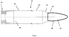
- FIG 4 there is provided a complete round 61, with a metal head unit 60, a polymer cartridge case 64, a cavity 65 for accepting propellant (propellant not shown), and a projectile 62, which located in the mouth 68 of the cartridge case.
- the upper end 63 of the cartridge case towards the shoulder 67, and neck portion 66, may be formed from the same or different polymer compositions.
- FIG 5a there is shown a head unit 70, with internal features provided, and a cavity 74a suitable for receiving the primer.
- the walls 72 of the head unit have a first diameter which is substantially that of the initial metal cup.
- the enlarged head rim is formed by the use of a heading tool 79, which impinges on the closed metal end 75a, forming an enlarged head rim 75b ( fig 5b ), and also forming a final sized primer cavity 74b.
- the head stamp 73 may be formed at the same time as the enlarged head rim 75b is formed.
- a head unit 80 wherein the metal coupling protrusion 82, has a series of projection 85, which could be minor surface keying, or notches, or adhesive, onto which a fibre ply 83, or fibre windings 84 is located, such that when the polymer case is formed thereon the metal coupling protrusion 82 projections 85, and fibre ply form a metal composite bond.
- the metal coupling protrusion 82 has a series of projection 85, which could be minor surface keying, or notches, or adhesive, onto which a fibre ply 83, or fibre windings 84 is located, such that when the polymer case is formed thereon the metal coupling protrusion 82 projections 85, and fibre ply form a metal composite bond.
- a metal cup 90 which is well known and is a well-defined starting material for preparing brass ammunition.
- the metal cup 90 is placed on a transfer press, and drawn through a series of dies.
- the first draw 91 shows how the cup starts to elongate, and during subsequent drawing operations the case tube 92 is produced.
- the production of the case tube is known to those proficient in the art.
- the case tube 92 is transferred to a forming press, where the metal head unit as defined herein in the earlier figures is formed to provide the enlarged head rim (shown in fig 1 .)
Abstract
The invention relates to a method of improved ammunition production, more specifically to an improved pressed metal head component suitable for a polymer tube cartridge The invention relates to a method of drawing and forming a metal head unit for use with a polymer case to form a polymer cartridge for use in a rifled barrel, comprising the steps of
i) providing a metal cup drawing it through one or more dies to provide a case tube, wherein the case tube has a closed head end with a first outer diameter and an elongate open end,
ii) trimming the elongate open end to form a metal coupling protrusion, said metal coupling protrusion with a second outer diameter, wherein the first diameter and second diameter are the same,
iii) forming, a primer cavity into the closed head end,
iv) forming internal and external features in the closed head end,
v) forming by a heading process, an enlarged head rim on the closed head end, such that said enlarged head rim has a third diameter which is larger than the second diameter of the open end.
Description
- The invention relates to a method of improved ammunition production, more specifically to an improved pressed metal head component suitable for a polymer tube cartridge.
- The manufacture of rounds for use in small arms follows a standardised process and involves the separate construction of a projectile and a case the latter comprising a primer and a propellant to propel the projectile. Both the case and projectile are typically formed from a ductile material that is capable of being reshaped through a series of dies. The projectile and case components are joined as part of the final stages of the process to form the round, which then undergoes a quality check.
- To reduce the burden on the user, new lightweight materials such as modern engineering polymers are being used in place of brass.
- According to a first aspect of the invention there is provided a method of drawing and forming a metal head unit for use with a polymer case to form a polymer cartridge for use in a rifled barrel, comprising the steps of
- i) providing a metal cup drawing it through one or more dies to provide a case tube, wherein the case tube has a closed head end with a first outer diameter and an elongate open end,
- ii) trimming the elongate open end to form a metal coupling protrusion, said metal coupling protrusion with a second outer diameter, wherein the first diameter and second diameter are the same,
- iii) forming, a primer cavity into the closed head end,
- iv) forming internal and external features in the closed head end,
- v) forming by a heading process, an enlarged head rim on the closed head end, such that said enlarged head rim has a third diameter which is larger than the second diameter of the open end;
- vi) forming a head stamp, and a through fire hole in the enlarged head, and an ejector groove under the enlarged head.
- The formation of brass cartridge cases is well known in the art, the cartridge cases are initially formed from a metal cup, these are commonplace components used in the drawing process for high velocity rounds, those typically used in rifled barrels. The metal cup is typically passed through a series of dies to form a longer, thinner metal cylinder. The base of the metal case tube is shaped to receive a percussion cap (primer cap) and ejection grooves, and head stamp.
- All the operations carried out at the head unit of the case in prior art brass cartridge case manufacture result in a reduction in size from the original drawn diameter of the original tube. During the forming process in a conventional brass round, at the formation of the head unit, a lip may be provided on the head unit, typically this may be of the order of less than 0.3mm, typically less than 3% which is an insufficient increase for the formation of the rim diameter of the polymer case head manufactured by this improved method.
- Typical prior art methods used to provide enlarged head rims, suitable for use with polymer cases, use machining processes i.e. turning on a lathe. In order to form a head unit and enlarged rim, the starting case tube must be at least as large as the required enlarged rim; these turning processes are slower production techniques, more costly, may require new equipment and increased waste material, a very inefficient process.
- The method defined herein, provides a means of using conventional drawing techniques and production lines, with slight modification, to provide an enlarged head rim, which has a diameter greater than the rest of the case, so that once engaged with a polymeric case, provides the required profile. The use of a heading process to form an enlarged head rim, allows the formation of the head stamp and bending over or peening of the existing case tube closed end to provide the enlarged head rim from the conventional sized metal cups. Sourcing or setting up new tooling to provide intermediate or oversized starting materials(i.e. metal cups), is a costly process.
- The method herein, allows the formation of the metal head unit of the selected calibre, from the metal cap that is typically used for that calibre round. For example a metal cup that is used to make a conventional 5.56mm brass case, can be used, and using 5.56mm conventional tooling, presses etc, to furnish a head unit with an enlarged rim suitable for a 5.56mm head unit suitable for a polymer case. The calibre may be selected from any calibre round.
- The metal cup may be selected from any metal or metal alloy, such as for example brass, aluminium, titanium, ferritic alloys, such as steel. Preferably the metal is brass.
- The use of annealing steps, cleaning steps, would be apparent to those skilled in the art.
- The enlarged head rim may be formed oversize and trimmed. The enlarged head rim has an outer diameter greater than the second diameter, of the metal coupling protrusion), in the range of from 105% to 130%, preferably 105% to 120%, more preferably in the range of from 105% to 115%.
- The elongate open end forms the metal coupling protrusion, which will engage with the polymer case. The elongate open end may be trimmed to the desired length to form the metal coupling protrusion. The metal coupling protrusion may be cylindrical, or machined, to provide a taper, ridges, cannelures, grooves. The end of the metal coupling protrusion may be turned over, bent or peened to provide further resistance and locking engagement with the polymer case.
- The metal coupling protrusion may further comprise surface projections, surface keying, to provide further increase in the strength of the mating between the metal coupling flange and the polymer case. Surface projections may interlock with any fibrous ply or fibrous filler material to provide further strength with a fibre reinforced polymer composite case.
- The polymer case may be pre-formed and affixed to the metal coupling protrusion or formed in situ.
- The polymer case may be formed in-situ around the metal head unit, by metal insert moulding. Some part or all of the polymer case and/or polymeric coupling may be integrally formed by metal insert moulding. The head may in a preferred process be loaded into a die cavity where a polymeric material is moulded around it to form a casing which will provide the final net shape for the cartridge case.
- Metal insert moulding is the insertion of a metal component during the moulding, casting, forming process of a polymer component and is well known to those proficient in said art. The metal head unit may be inserted before, during or even post forming process, before the polymer moulding process has resulted in a final cured product. The polymer moulding processes may be selected from any known process, such as, for example, injection, compression, GRP, extrusion, extrusion blow moulding, SMC/DMC, structural foam, and rotational moulding.
- The polymeric case when formed as a separate component may be affixed to the metal coupling protrusion by a thermal weld, ultrasonic weld, heat shrink, adhesive, crimp, clamped, interlocked with said metal protrusion, to form a gas tight seal. The weld may be any thermal heat source, such as, for example induction, flame, laser or ultrasonic.
- The polymer case may comprise multiple sections, such as, for example a polymeric coupling end, and an open end (mouth) for receiving a projectile, or the mouth end may be closed for forming a blank.
- The polymer case may comprise one or more intermediate sections. The sections, polymeric coupling end, and projectile/blank end may have different rigidities, and physical properties. The polymer case may have one, two, three or more sections, each section may be independently selected from a different polymer, or the same polymer with different chemical or physical properties, depending on densities, curing agents, curing process, fillers, fibres or other additives.
- The polymer case may be formed as a monolithic polymer case. The monolithic polymer case may have different chemical or physical properties, at various points along its construction, by, varying densities or variable loading of fillers, fibres or other additives therein.
- The polymer case may be located at least in part over the outer diameter of the second open end of the closed head end. Preferably the polymer case outer diameter and enlarged head rim diameter are substantially the same.
- In one arrangement there may be a further circumferential groove below the ejector groove, to accommodate a retaining portion of polymer case.
- The polymer case preferably comprises a polymeric coupling end, which engages with the metal coupling protrusion. The polymeric coupling end and metal coupling protrusion may be a male and female co-operative locking arrangement.
- In a preferred arrangement the polymeric coupling end is a female coupling portion. Preferably the female coupling portion comprises two polymeric skirt portions which engage with the metal coupling protrusion. The two skirt portions may envelope the metal coupling protrusion. The two skirt portions may be an outer skirt portion and an inner skirt portion. The outer skirt portion may form part of the outside of the polymeric case. The outer polymeric skirt portion may comprise the retaining portion, which engages with the further circumferential groove, which is located under the ejection groove.
- The inner skirt portion goes inside the head unit, which will form part of the powder retaining cavity of the formed cartridge case. The inner polymeric skirt portion may comprise a further retaining portion, which engages with the flash hole aperture as formed internally within the metal head unit.
- The polymeric case may be formed from any polymer, such as for example, thermoset, thermoplastics, such polymers may be block polymers, copolymers, elastomers, fluoroelastomers and combinations thereof. The polymers used in polymer cartridge cases are known in the art.
- The polymeric case may be a fibre reinforced polymer composite case. The fibres may be fibre ply, fibres, chopped fibre, fibre threaded windings. The fibres may be any commonly used fibre such as, for example, glass, carbon, polymers, such as, for example polyarimid, metals.
- The polymeric case may comprise particulate fillers, such as, for example, filaments, leaf or other particles.
- The particulate fillers may be any material, such as, for example metals, metalloids, ceramics, metal alloys thereof. The particulate fillers may be nano particulate, or multimodal loaded polymer composites. The nano particulate may be carbon, such as for example carbon nanotubes, graphene, graphitic fillers.
- The fibres and/or particulate fillers may be present in the range of 5 to 80%, and the remainder the respective curable monomer to form the selected polymer case.
- There may be some fibres affixed to the metal coupling protrusion prior to affixing or inert metal moulding the polymeric case, so as to provide a composite-metal bond.
- According to a further aspect of the invention there is provided a polymeric cartridge case ammunition round, comprising a
metal head end, further comprising an enlarged head rim, said enlarged head rim having been formed by heading of the metal head end, such that said diameter of the enlarged head rim is in the range of from 105% to 115% of the metal head, an ejector groove located under said enlarged head rim, and at least one further circumferential groove located under said ejector groove,
said metal head end at the distal end to the enlarge head rim, comprising a metal coupling protrusion,
a polymeric case, comprising a polymeric coupling end and a projectile receiving end, said polymeric coupling end engages with the metal coupling protrusion. - Preferably the polymeric coupling end comprises a female coupling portion with two polymeric skirt portions, which engages either side of said metal coupling protrusion, wherein at least one of the polymeric skirt portions comprises the retaining portion which engages with the further circumferential groove.
- The drawing process, on a transfer press, of a metal cup into a case tube is very well known to those skilled in the art.
- The first station in the press, is a portion of a press, which comprises a mandrel (or punch) or both and at least one shaped die which are caused to move together under high pressure to cause the initial elongation of a metal cup;
- The cup is further elongated or extruded by successive stations having different diameter or shaped punches, mandrels and/or floating dies. The stations are reached by moving the extrudable outer sheath between each station using feed fingers that individually load and unload the extrudable outer sheath; blind-end down into the sequence of floating dies.
- The near final formed extruded outer sheath is passed through further stations on a forming press, the first of which is a portion of a press, which comprises a mandrel (or punch) or both and at least one shaped die which are caused to move together under high pressure to cause the final forming of the external and internal head features, the method defined herein provides the heading step of providing the enlarged diameter rim portion, prior to any machining/trim to the final dimensions.
- Once formed the head undergoes a visual and multi-gauge inspection check. The head is placed on a test mandrel where it is turned through 360 degrees, during which time the wall thickness is measured and displayed. If the head passes this inspection it is passed to an area where final machining takes place.
- Whilst the method and case has been described above, it extends to any inventive combination of the features set out above, or in the following description, drawings or claims.
- Exemplary embodiments of the device in accordance with the invention will now be described with reference to the accompanying drawings in which:-
-
Figure 1 a and b show a metal head unit -
Figure 2 shows a bonded arrangement of a polymer case and metal head unit -
Figure 3 shows an alternative bonded arrangement of a polymer case and metal head unit. -
Figure 4 shows a polymer cased ammunition round. -
Figure 5a and 5b show the formation of the enlarged head rim -
Figure 6 shows an improved metal-composite bond arrangement -
Figure 7 shows a metal cup and subsequent drawn tubes. - Referring to
Figures 1a and 1b , there is provided ametal head 1, which comprises anenlarged head rim 3, on ahead unit 11. Thehead unit 11, comprises anejector groove 10, and at least one furthercircumferential groove 6, to accommodate a portion of the polymer cartridge tube (not shown). Themetal coupling protrusion 2, forms a coupling surface with the polymer cartridge tube (not shown). - The
head unit 11, comprises aprimer cavity 4, and aflash hole 7, to allow the output from the primer (removed for clarity) to transfer through to propellant in the final cartridge. The internal features such as theinternal shoulder 8 andflash hole aperture 9, are produced during the forming process. - Referring to
Figure 2 , there is provided ametal head 20, which comprises anenlarged head rim 25, on ahead unit 35. Thehead unit 35, comprises an at least one furthercircumferential groove 26, which accommodates a retaining portion of thepolymer case 34. Theejector groove 30 is in part formed by theenlarged head rim 25, and the retaining portion of thepolymer case 34. Themetal coupling protrusion 22 engages with thepolymer case 31, at thepolymeric coupling end 33, and the forms an abuttingengagement 32. - The
head unit 35, comprises aprimer cavity 24, and aflash hole 27, to allow the output from the primer (removed for clarity) to transfer through to propellant in the final cartridge. The internal features such as theinternal shoulder 28 andflash hole aperture 29, are produced during the forming process. - Referring to
Figure 3 , there is provided ametal head 40, which comprises anenlarged head rim 45, on ahead unit 55. Thehead unit 55, comprises an at least one furthercircumferential groove 46, which accommodates a retaining portion of thepolymer case 54. Theejector groove 50 is in part formed by theenlarged head rim 45, and the retaining portion of thepolymer case 54. Themetal coupling protrusion 42 engages with thepolymer case 51. The femalepolymeric coupling end 53, comprising the twoskirt portions metal coupling protrusion 42. - The
head unit 55, comprises aprimer cavity 44, and aflash hole 47. In this arrangement theflash hole 47 is formed by the innerpolymeric skirt portion 52a, which comprises a further retainingportion 59, which engages with theflash hole aperture 49. The further retainingportion 59 forms a narrowerflash hole aperture 47. Theflash hole 47 allows the output from the primer (removed for clarity) to transfer through to propellant in the final cartridge. Theinner skirt portion 52a extends 58 and attaches to theinternal shoulder 48 along its length. - The outer
polymeric skirt portion 52b extends down the outside themetal coupling protrusion 42. Theouter polymeric skirt 52b and enlarged head rim 45 have substantially the same diameter. - Turning to
figure 4 , there is provided acomplete round 61, with ametal head unit 60, apolymer cartridge case 64, acavity 65 for accepting propellant (propellant not shown), and a projectile 62, which located in the mouth 68 of the cartridge case. Theupper end 63 of the cartridge case towards theshoulder 67, andneck portion 66, may be formed from the same or different polymer compositions. - Turning to
figure 5a , there is shown ahead unit 70, with internal features provided, and acavity 74a suitable for receiving the primer. Thewalls 72 of the head unit have a first diameter which is substantially that of the initial metal cup. The enlarged head rim is formed by the use of a headingtool 79, which impinges on theclosed metal end 75a, forming anenlarged head rim 75b (fig 5b ), and also forming a finalsized primer cavity 74b. Thehead stamp 73, may be formed at the same time as theenlarged head rim 75b is formed. - Turning to
fig 6 , there is provided ahead unit 80, wherein themetal coupling protrusion 82, has a series ofprojection 85, which could be minor surface keying, or notches, or adhesive, onto which afibre ply 83, orfibre windings 84 is located, such that when the polymer case is formed thereon themetal coupling protrusion 82projections 85, and fibre ply form a metal composite bond. - Turning to
fig 7 , there is shown ametal cup 90, which is well known and is a well-defined starting material for preparing brass ammunition. Themetal cup 90 is placed on a transfer press, and drawn through a series of dies. Thefirst draw 91, shows how the cup starts to elongate, and during subsequent drawing operations thecase tube 92 is produced. The production of the case tube is known to those proficient in the art. Once thecase tube 92 has been produced it is transferred to a forming press, where the metal head unit as defined herein in the earlier figures is formed to provide the enlarged head rim (shown infig 1 .)
Claims (15)
- A method of drawing and forming a metal head unit for use with a polymer case to form a polymer cartridge for use in a rifled barrel, comprising the steps ofi) providing a metal cup drawing it through one or more dies to provide a case tube, wherein the case tube has a closed head end with a first outer diameter and an elongate open end,ii) trimming the elongate open end to form a metal coupling protrusion, said metal coupling protrusion with a second outer diameter, wherein the first diameter and second diameter are the same,iii) forming, a primer cavity into the closed head end,iv) forming internal and external features in the closed head end,v) forming by a heading process, an enlarged head rim on the closed head end, such that said enlarged head rim has a third diameter which is larger than the second diameter of the open end.
- A method according to claim 1, further comprisingvi) forming a head stamp on the enlarged head rim, and piercing a through fire hole, and forming an ejector groove under the enlarged head.
- A method according to claim 1 or 2, wherein a polymer case is located inside, outside, both inside and outside, or at least in part over the outer diameter of the metal coupling protrusion.
- A method according to any one of the preceding claims, wherein the polymer case's outer diameter and enlarged head rim diameter are substantially the same.
- A method according to any one of claims 2 to 4, wherein the enlarged head rim is formed by a heading process which simultaneously applies the head stamp.
- A method according to any one of the preceding claims wherein the enlarged head rim has an outer diameter greater than the second diameter in the range of from 105% to 115%.
- A method according to any one of the preceding claims wherein there is a further circumferential groove below the ejector groove, to accommodate a retaining portion of the polymer case.
- A method according to any one of the preceding claims wherein said polymeric case comprises a polymeric coupling end, and an open end for receiving a projectile or closed end for forming a blank.
- A method according to claim 8, wherein the polymeric coupling end engages with the metal coupling protrusion.
- A method according to claim 8 or 9, wherein the polymeric coupling end is a female coupling portion with at least two polymeric skirt portions which engage with the metal coupling protrusion.
- A method according to claim 10, wherein one of the at least two polymeric skirt portions is an outer polymeric skirt portion, which comprises the retaining portion, which engages with the further circumferential groove.
- A method according to any one of claims 10 or 11, wherein one of the at least two polymeric skirt portions is an inner polymeric skirt portion, which comprises a further retaining portion, which engages with the flash hole.
- A method according to anyone of the preceding claims, wherein the polymeric case is fixed to the metal protrusion by a weld, adhesive, crimp, clamped, interlocked with said metal protrusion, metal insert moulding.
- A method according to anyone of the preceding claims wherein the polymeric case is formed from, thermoset, thermoplastic, block polymers, copolymers, elastomers, fluoroelastomers, and fibre reinforced polymer composites and combinations thereof.
- A polymeric cartridge case ammunition round, comprising a
metal head end, further comprising an enlarged head rim, said enlarged head rim formed by heading of the metal head end, such that said diameter of the enlarged head rim in the range of 105% to 115% of the metal head, an ejector groove located under said enlarged head rim, and at least one further circumferential groove located under said ejector groove,
said metal head end at the distal end to the enlarge head rim, comprising a metal coupling protrusion,
a polymeric case, comprising a polymeric coupling end and a projectile receiving end, said polymeric coupling end engages with the metal coupling protrusion.
Priority Applications (6)
| Application Number | Priority Date | Filing Date | Title |
|---|---|---|---|
| EP18275039.8A EP3540365A1 (en) | 2018-03-13 | 2018-03-13 | Improved metal head unit for use with a polymer case to form a polymer cartridge |
| US16/979,646 US11125540B2 (en) | 2018-03-13 | 2019-03-05 | Pressed head |
| CA3092806A CA3092806A1 (en) | 2018-03-13 | 2019-03-05 | Improved pressed head |
| EP19709552.4A EP3765812B1 (en) | 2018-03-13 | 2019-03-05 | Improved metal head unit for use with a polymer case to form a cartridge |
| AU2019233783A AU2019233783B2 (en) | 2018-03-13 | 2019-03-05 | Improved pressed head |
| PCT/GB2019/050603 WO2019175539A1 (en) | 2018-03-13 | 2019-03-05 | Improved pressed head |
Applications Claiming Priority (1)
| Application Number | Priority Date | Filing Date | Title |
|---|---|---|---|
| EP18275039.8A EP3540365A1 (en) | 2018-03-13 | 2018-03-13 | Improved metal head unit for use with a polymer case to form a polymer cartridge |
Publications (1)
| Publication Number | Publication Date |
|---|---|
| EP3540365A1 true EP3540365A1 (en) | 2019-09-18 |
Family
ID=61655711
Family Applications (1)
| Application Number | Title | Priority Date | Filing Date |
|---|---|---|---|
| EP18275039.8A Ceased EP3540365A1 (en) | 2018-03-13 | 2018-03-13 | Improved metal head unit for use with a polymer case to form a polymer cartridge |
Country Status (1)
| Country | Link |
|---|---|
| EP (1) | EP3540365A1 (en) |
Cited By (2)
| Publication number | Priority date | Publication date | Assignee | Title |
|---|---|---|---|---|
| US20210341266A1 (en) * | 2010-11-10 | 2021-11-04 | True Velocity Ip Holdings, Llc | Stamped primer insert for use in polymer ammunition |
| US20220260347A1 (en) * | 2016-07-27 | 2022-08-18 | Shell Shock Technologies LLC | Ammunition casing having a cannelure with step |
Citations (6)
| Publication number | Priority date | Publication date | Assignee | Title |
|---|---|---|---|---|
| US2904873A (en) * | 1956-09-12 | 1959-09-22 | Henry F Hild | Drawn steel cartridge case and its manufacture |
| GB1015516A (en) * | 1963-07-16 | 1966-01-05 | Remington Arms Co Inc | Improvements in or relating to firearm cartridges |
| GB1281711A (en) * | 1968-07-11 | 1972-07-12 | Harvey Aluminum Inc | Aluminium alloy cartridge cases |
| WO2012047615A1 (en) * | 2010-10-07 | 2012-04-12 | Nylon Corporation Of America, Inc. | Ammunition cartridge case bodies made with polymeric nanocomposite material |
| US20120180688A1 (en) * | 2011-01-14 | 2012-07-19 | Pcp Ammunition Company Llc | High strength polymer-based cartridge casing and manufacturing method |
| US20140260925A1 (en) * | 2013-03-15 | 2014-09-18 | Cybernet Systems Corporation | Integrated polymer and metal case ammunition manufacturing system and method |
-
2018
- 2018-03-13 EP EP18275039.8A patent/EP3540365A1/en not_active Ceased
Patent Citations (6)
| Publication number | Priority date | Publication date | Assignee | Title |
|---|---|---|---|---|
| US2904873A (en) * | 1956-09-12 | 1959-09-22 | Henry F Hild | Drawn steel cartridge case and its manufacture |
| GB1015516A (en) * | 1963-07-16 | 1966-01-05 | Remington Arms Co Inc | Improvements in or relating to firearm cartridges |
| GB1281711A (en) * | 1968-07-11 | 1972-07-12 | Harvey Aluminum Inc | Aluminium alloy cartridge cases |
| WO2012047615A1 (en) * | 2010-10-07 | 2012-04-12 | Nylon Corporation Of America, Inc. | Ammunition cartridge case bodies made with polymeric nanocomposite material |
| US20120180688A1 (en) * | 2011-01-14 | 2012-07-19 | Pcp Ammunition Company Llc | High strength polymer-based cartridge casing and manufacturing method |
| US20140260925A1 (en) * | 2013-03-15 | 2014-09-18 | Cybernet Systems Corporation | Integrated polymer and metal case ammunition manufacturing system and method |
Cited By (3)
| Publication number | Priority date | Publication date | Assignee | Title |
|---|---|---|---|---|
| US20210341266A1 (en) * | 2010-11-10 | 2021-11-04 | True Velocity Ip Holdings, Llc | Stamped primer insert for use in polymer ammunition |
| US20220260347A1 (en) * | 2016-07-27 | 2022-08-18 | Shell Shock Technologies LLC | Ammunition casing having a cannelure with step |
| US11933592B2 (en) * | 2016-07-27 | 2024-03-19 | Shell Shock Technologies Inc | Ammunition casing having a cannelure with step |
Similar Documents
| Publication | Publication Date | Title |
|---|---|---|
| AU2019233783B2 (en) | Improved pressed head | |
| US3242789A (en) | Method of making plastic cartridge case | |
| US3171350A (en) | Biaxially oriented plastic shotshell | |
| EP3540365A1 (en) | Improved metal head unit for use with a polymer case to form a polymer cartridge | |
| EP0000438B1 (en) | Process for producing tubular articles | |
| US20210129224A1 (en) | Shell case design utilizing metal injection molding | |
| GB2571951A (en) | Improved pressed head | |
| US3351014A (en) | Biaxially oriented plastic shot shell | |
| US3363296A (en) | Shaping tubular shells and ammunition cartridges | |
| CN210023521U (en) | Composite pipe flanging withholding joint processing equipment | |
| US10704875B2 (en) | Ammunition production | |
| EP1704944B1 (en) | Airbag tube with cold-formed charging head and procedure for obtaining the same | |
| EP4086567A1 (en) | Lightweight end cap | |
| EP4086566A1 (en) | Lightweight end cap | |
| EP4086565A1 (en) | Improved end cap | |
| US3125924A (en) | Charles e | |
| US3276375A (en) | Plastic article making | |
| AU2014320132A1 (en) | Improved ammunition production | |
| GB2606368A (en) | Lightweight end cap | |
| WO2022234247A1 (en) | Lightweight end cap | |
| US3611938A (en) | Plastic shot shell | |
| WO2022234245A1 (en) | Lightweight end cap | |
| EP4334669A1 (en) | Improved end cap | |
| GB2606367A (en) | Lightweight end cap | |
| CN111823468A (en) | Steel-lined tetrafluoride pipe and forming process thereof |
Legal Events
| Date | Code | Title | Description |
|---|---|---|---|
| PUAI | Public reference made under article 153(3) epc to a published international application that has entered the european phase |
Free format text: ORIGINAL CODE: 0009012 |
|
| AK | Designated contracting states |
Kind code of ref document: A1 Designated state(s): AL AT BE BG CH CY CZ DE DK EE ES FI FR GB GR HR HU IE IS IT LI LT LU LV MC MK MT NL NO PL PT RO RS SE SI SK SM TR |
|
| AX | Request for extension of the european patent |
Extension state: BA ME |
|
| STAA | Information on the status of an ep patent application or granted ep patent |
Free format text: STATUS: THE APPLICATION HAS BEEN REFUSED |
|
| 18R | Application refused |
Effective date: 20191005 |