EP3540324A1 - Heating medium circulation system - Google Patents
Heating medium circulation system Download PDFInfo
- Publication number
- EP3540324A1 EP3540324A1 EP16921139.8A EP16921139A EP3540324A1 EP 3540324 A1 EP3540324 A1 EP 3540324A1 EP 16921139 A EP16921139 A EP 16921139A EP 3540324 A1 EP3540324 A1 EP 3540324A1
- Authority
- EP
- European Patent Office
- Prior art keywords
- heating medium
- heating
- storage tank
- heat
- flow
- Prior art date
- Legal status (The legal status is an assumption and is not a legal conclusion. Google has not performed a legal analysis and makes no representation as to the accuracy of the status listed.)
- Granted
Links
- 238000010438 heat treatment Methods 0.000 title claims abstract description 283
- 238000005338 heat storage Methods 0.000 claims abstract description 87
- XLYOFNOQVPJJNP-UHFFFAOYSA-N water Substances O XLYOFNOQVPJJNP-UHFFFAOYSA-N 0.000 claims description 55
- 239000003507 refrigerant Substances 0.000 description 14
- 238000011144 upstream manufacturing Methods 0.000 description 9
- 230000006870 function Effects 0.000 description 8
- 238000004378 air conditioning Methods 0.000 description 6
- 230000006837 decompression Effects 0.000 description 4
- 239000012530 fluid Substances 0.000 description 4
- LYCAIKOWRPUZTN-UHFFFAOYSA-N Ethylene glycol Chemical compound OCCO LYCAIKOWRPUZTN-UHFFFAOYSA-N 0.000 description 3
- 239000007864 aqueous solution Substances 0.000 description 2
- 238000002485 combustion reaction Methods 0.000 description 2
- 238000004891 communication Methods 0.000 description 2
- 230000000694 effects Effects 0.000 description 2
- UXVMQQNJUSDDNG-UHFFFAOYSA-L Calcium chloride Chemical compound [Cl-].[Cl-].[Ca+2] UXVMQQNJUSDDNG-UHFFFAOYSA-L 0.000 description 1
- LFQSCWFLJHTTHZ-UHFFFAOYSA-N Ethanol Chemical compound CCO LFQSCWFLJHTTHZ-UHFFFAOYSA-N 0.000 description 1
- 239000003570 air Substances 0.000 description 1
- 230000002457 bidirectional effect Effects 0.000 description 1
- 229910001628 calcium chloride Inorganic materials 0.000 description 1
- 239000001110 calcium chloride Substances 0.000 description 1
- 239000003245 coal Substances 0.000 description 1
- 239000002131 composite material Substances 0.000 description 1
- 238000005260 corrosion Methods 0.000 description 1
- 230000007797 corrosion Effects 0.000 description 1
- 238000009429 electrical wiring Methods 0.000 description 1
- 239000000446 fuel Substances 0.000 description 1
- 239000000295 fuel oil Substances 0.000 description 1
- 239000007789 gas Substances 0.000 description 1
- 239000003673 groundwater Substances 0.000 description 1
- 239000003350 kerosene Substances 0.000 description 1
- 238000000034 method Methods 0.000 description 1
- 230000004044 response Effects 0.000 description 1
- 239000004065 semiconductor Substances 0.000 description 1
- 239000000243 solution Substances 0.000 description 1
- 238000013517 stratification Methods 0.000 description 1
- 239000002351 wastewater Substances 0.000 description 1
Images
Classifications
-
- F—MECHANICAL ENGINEERING; LIGHTING; HEATING; WEAPONS; BLASTING
- F24—HEATING; RANGES; VENTILATING
- F24D—DOMESTIC- OR SPACE-HEATING SYSTEMS, e.g. CENTRAL HEATING SYSTEMS; DOMESTIC HOT-WATER SUPPLY SYSTEMS; ELEMENTS OR COMPONENTS THEREFOR
- F24D11/00—Central heating systems using heat accumulated in storage masses
- F24D11/002—Central heating systems using heat accumulated in storage masses water heating system
-
- F—MECHANICAL ENGINEERING; LIGHTING; HEATING; WEAPONS; BLASTING
- F24—HEATING; RANGES; VENTILATING
- F24D—DOMESTIC- OR SPACE-HEATING SYSTEMS, e.g. CENTRAL HEATING SYSTEMS; DOMESTIC HOT-WATER SUPPLY SYSTEMS; ELEMENTS OR COMPONENTS THEREFOR
- F24D19/00—Details
- F24D19/10—Arrangement or mounting of control or safety devices
- F24D19/1006—Arrangement or mounting of control or safety devices for water heating systems
- F24D19/1066—Arrangement or mounting of control or safety devices for water heating systems for the combination of central heating and domestic hot water
- F24D19/1069—Arrangement or mounting of control or safety devices for water heating systems for the combination of central heating and domestic hot water regulation in function of the temperature of the domestic hot water
-
- F—MECHANICAL ENGINEERING; LIGHTING; HEATING; WEAPONS; BLASTING
- F24—HEATING; RANGES; VENTILATING
- F24D—DOMESTIC- OR SPACE-HEATING SYSTEMS, e.g. CENTRAL HEATING SYSTEMS; DOMESTIC HOT-WATER SUPPLY SYSTEMS; ELEMENTS OR COMPONENTS THEREFOR
- F24D3/00—Hot-water central heating systems
- F24D3/08—Hot-water central heating systems in combination with systems for domestic hot-water supply
- F24D3/087—Tap water heat exchangers specially adapted therefore
-
- F—MECHANICAL ENGINEERING; LIGHTING; HEATING; WEAPONS; BLASTING
- F24—HEATING; RANGES; VENTILATING
- F24H—FLUID HEATERS, e.g. WATER OR AIR HEATERS, HAVING HEAT-GENERATING MEANS, e.g. HEAT PUMPS, IN GENERAL
- F24H15/00—Control of fluid heaters
- F24H15/30—Control of fluid heaters characterised by control outputs; characterised by the components to be controlled
- F24H15/375—Control of heat pumps
-
- F—MECHANICAL ENGINEERING; LIGHTING; HEATING; WEAPONS; BLASTING
- F24—HEATING; RANGES; VENTILATING
- F24D—DOMESTIC- OR SPACE-HEATING SYSTEMS, e.g. CENTRAL HEATING SYSTEMS; DOMESTIC HOT-WATER SUPPLY SYSTEMS; ELEMENTS OR COMPONENTS THEREFOR
- F24D11/00—Central heating systems using heat accumulated in storage masses
- F24D11/02—Central heating systems using heat accumulated in storage masses using heat pumps
- F24D11/0214—Central heating systems using heat accumulated in storage masses using heat pumps water heating system
-
- F—MECHANICAL ENGINEERING; LIGHTING; HEATING; WEAPONS; BLASTING
- F24—HEATING; RANGES; VENTILATING
- F24D—DOMESTIC- OR SPACE-HEATING SYSTEMS, e.g. CENTRAL HEATING SYSTEMS; DOMESTIC HOT-WATER SUPPLY SYSTEMS; ELEMENTS OR COMPONENTS THEREFOR
- F24D2200/00—Heat sources or energy sources
- F24D2200/12—Heat pump
- F24D2200/123—Compression type heat pumps
-
- F—MECHANICAL ENGINEERING; LIGHTING; HEATING; WEAPONS; BLASTING
- F24—HEATING; RANGES; VENTILATING
- F24D—DOMESTIC- OR SPACE-HEATING SYSTEMS, e.g. CENTRAL HEATING SYSTEMS; DOMESTIC HOT-WATER SUPPLY SYSTEMS; ELEMENTS OR COMPONENTS THEREFOR
- F24D2220/00—Components of central heating installations excluding heat sources
- F24D2220/02—Fluid distribution means
- F24D2220/0235—Three-way-valves
-
- F—MECHANICAL ENGINEERING; LIGHTING; HEATING; WEAPONS; BLASTING
- F24—HEATING; RANGES; VENTILATING
- F24D—DOMESTIC- OR SPACE-HEATING SYSTEMS, e.g. CENTRAL HEATING SYSTEMS; DOMESTIC HOT-WATER SUPPLY SYSTEMS; ELEMENTS OR COMPONENTS THEREFOR
- F24D2220/00—Components of central heating installations excluding heat sources
- F24D2220/02—Fluid distribution means
- F24D2220/025—Check valves
-
- F—MECHANICAL ENGINEERING; LIGHTING; HEATING; WEAPONS; BLASTING
- F24—HEATING; RANGES; VENTILATING
- F24D—DOMESTIC- OR SPACE-HEATING SYSTEMS, e.g. CENTRAL HEATING SYSTEMS; DOMESTIC HOT-WATER SUPPLY SYSTEMS; ELEMENTS OR COMPONENTS THEREFOR
- F24D2220/00—Components of central heating installations excluding heat sources
- F24D2220/08—Storage tanks
-
- F—MECHANICAL ENGINEERING; LIGHTING; HEATING; WEAPONS; BLASTING
- F24—HEATING; RANGES; VENTILATING
- F24H—FLUID HEATERS, e.g. WATER OR AIR HEATERS, HAVING HEAT-GENERATING MEANS, e.g. HEAT PUMPS, IN GENERAL
- F24H15/00—Control of fluid heaters
- F24H15/10—Control of fluid heaters characterised by the purpose of the control
- F24H15/156—Reducing the quantity of energy consumed; Increasing efficiency
-
- F—MECHANICAL ENGINEERING; LIGHTING; HEATING; WEAPONS; BLASTING
- F24—HEATING; RANGES; VENTILATING
- F24H—FLUID HEATERS, e.g. WATER OR AIR HEATERS, HAVING HEAT-GENERATING MEANS, e.g. HEAT PUMPS, IN GENERAL
- F24H15/00—Control of fluid heaters
- F24H15/10—Control of fluid heaters characterised by the purpose of the control
- F24H15/174—Supplying heated water with desired temperature or desired range of temperature
-
- F—MECHANICAL ENGINEERING; LIGHTING; HEATING; WEAPONS; BLASTING
- F24—HEATING; RANGES; VENTILATING
- F24H—FLUID HEATERS, e.g. WATER OR AIR HEATERS, HAVING HEAT-GENERATING MEANS, e.g. HEAT PUMPS, IN GENERAL
- F24H15/00—Control of fluid heaters
- F24H15/20—Control of fluid heaters characterised by control inputs
- F24H15/281—Input from user
Definitions
- the present invention relates to a heating medium circulation system.
- a heat storage hot-water supply and air conditioning device disclosed in PTL 1 shown below includes a heat storage tank that stores a heating medium that is heated or cooled by a heat pump device, and an air conditioning heat exchanger.
- the heat storage hot-water supply and air conditioning device is capable of circulating the heating medium from the heat pump device or the heat storage tank to the air conditioning heat exchanger.
- the conventional system described above switches between an operation in which the heating medium is supplied from the heat pump device to the air conditioning heat exchanger and an operation in which the heating medium is supplied from the heat storage tank to the air conditioning heat exchanger using two three-way valves (a heat storage switching valve (19) and a heat discharge switching valve (20)). Consequently, a problem arises in that a device configuration is complicated.
- the present invention has been made in order to solve the above problem, and an object thereof is to provide a heating medium circulation system capable of enabling, using a simple device configuration, an operation in which a heating medium is caused to flow into a supply channel leading to a heat demand section from a heat storage tank, and an operation in which the heating medium heated by heating means is caused to flow into the supply channel without passing through the heat storage tank.
- a heating medium circulation system includes: heating means configured to heat a heating medium; a heat storage tank configured to store the heating medium heated by the heating means; a supply channel through which the heating medium supplied to a heat demand section flows; a first flow channel through which the heating medium flowing out from the heating means is caused to flow into the supply channel without passing through the heat storage tank; a second flow channel through which the heating medium flowing out from the heating means is caused to flow into the heat storage tank; flow channel switching means configured to switch between the first flow channel and the second flow channel; a third flow channel through which the heating medium flowing out from the heat storage tank is caused to flow into the supply channel; and a check valve disposed in the third flow channel.
- the heating medium circulation system of the present invention it becomes possible to enable, using the simple device configuration, the operation in which the heating medium is caused to flow into the supply channel leading to the heat demand section from the heat storage tank, and the operation in which the heating medium heated by the heating means is caused to flow into the supply channel without passing through the heat storage tank.
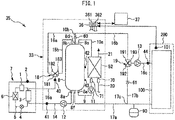
- Fig. 1 is a view showing a heating medium circulation system 35 according to Embodiment 1.
- the heating medium circulation system 35 includes a heat pump device 7 and a tank unit 33.
- the heat pump device 7 is an example of heating means that heats a heating medium.
- a heat storage tank 8 is installed inside the casing of the tank unit 33.
- the heat storage tank 8 stores the heating medium heated by the heat pump device 7.
- the heating medium in the present invention may be water.
- the heating medium in the present invention may also be a fluid heating medium other than water such as, e.g., a calcium chloride aqueous solution, an ethylene glycol aqueous solution, or alcohol.
- a thermal stratification in which the upper side has a high temperature and the lower side has a low temperature can be formed due to a difference in the density of the heating medium caused by a difference in temperature.
- the heat pump device 7 and the tank unit 33 are connected to each other via a fourth flow channel 14, a fifth flow channel 15a, and electrical wiring (the depiction thereof is omitted).
- the tank unit 33 may be installed outdoors or may also be installed indoors.
- the heat pump device 7 may be installed outdoors.
- the heating medium circulation system 35 of the present embodiment has a configuration in which the heat pump device 7 and the tank unit 33 are separated from each other. Instead of this configuration, the tank unit 33 may be integrated with the heat pump device 7.
- the heat pump device 7 includes a refrigerant circuit in which a compressor 1, a first heat exchanger 3, a decompression device 4, and a second heat exchanger 6 are annularly connected by refrigerant piping 5.
- a refrigerant sealed in the refrigerant circuit may be, e.g., CO 2 .
- the heat pump device 7 performs an operation of a heat pump cycle using the refrigerant circuit.
- heat is exchanged between a refrigerant having high temperature and high pressure compressed by the compressor 1 and the heating medium flowing in from the fourth flow channel 14.
- the decompression device 4 expands the high-pressure refrigerant having passed through the first heat exchanger 3 to turn the high-pressure refrigerant into a low-pressure refrigerant.
- the decompression device 4 may be an expansion valve.
- the second heat exchanger 6 causes heat to be exchanged between the low-pressure refrigerant and a fluid.
- the fluid may be any of, e.g., outside air, groundwater, wastewater, and solar-heated water.
- the heat pump device 7 may include a blower or a pump (the depiction thereof is omitted) for sending the fluid to the second heat exchanger 6.
- the heat pump device 7 in the present embodiment includes an outside air temperature sensor 2 that detects outside air temperature.
- the heating means in the present invention is not limited to the heat pump device 7.
- the heating means may also be a combustion heater that performs heating by using heat of combustion of fuel such as gas, kerosene, heavy oil, or coal.
- the heating means may also be a device that heats the heating medium using solar heat.
- a control device 36 is provided inside the tank unit 33. Valves, pumps, actuators such as the compressor 1 and the like, and sensors of the tank unit 33 and the heat pump device 7 are electrically connected to the control device 36. The control device 36 controls various operations described later.
- a terminal device 37 has the function of receiving operations of a user related to change of operation commands and set values.
- the terminal device 37 is an example of an operation terminal or a user interface.
- the control device 36 and the terminal device 37 are connected to each other so as to be capable of bidirectional data communication by using wired or wireless communication.
- the terminal device 37 is equipped with a display section that displays information on the state of the heating medium circulation system 35 or the like, an operation section operated by the user such as a switch or the like, a speaker, and a microphone, though the depiction thereof is omitted.
- the terminal device 37 may be installed indoors.
- the heating medium circulation system 35 may include a plurality of the terminal devices 37 that are installed at different places.
- the tank unit 33 further includes various components and piping described below in addition to the heat storage tank 8 and the control device 36.
- a plurality of tank temperature sensors 42 and 43 are mounted to the surface of the heat storage tank 8 at positions having different heights.
- the control device 36 can calculate the amount of stored heat and the amount of a high-temperature heating medium in the heat storage tank 8 by detecting the distribution of the temperature of the heating medium in the heat storage tank 8 using the tank temperature sensors 42 and 43.
- Two tank temperature sensors 42 and 43 are mounted in the configuration shown in the drawing, but three or more tank temperature sensors may be mounted to the heat storage tank 8.
- the control device 36 may control start and stop timings of a heat accumulating operation based on the amount of stored heat in the heat storage tank 8.
- the heat accumulating operation is the operation in which the heating medium heated by the heat pump device 7 is caused to flow into the heat storage tank 8.
- the heat storage tank 8 includes a first outlet 8a, an inlet 8b, a second outlet 8c, a third outlet 8d, a first return port 8e, and a second return port 8f.
- the first outlet 8a, the first return port 8e, and the second return port 8f are positioned in the lower portion of the heat storage tank 8.
- the inlet 8b, the second outlet 8c, and the third outlet 8d are positioned in the upper portion of the heat storage tank 8.
- the fourth flow channel 14 has a first end connected to the first outlet 8a of the heat storage tank 8, and a second end connected to the inlet of the heating medium of the first heat exchanger 3 of the heat pump device 7.
- a first circulation pump 12 capable of circulating the heating medium to the heat pump device 7 is connected to some midpoint of the fourth flow channel 14. In the configuration shown in the drawing, the first circulation pump 12 is disposed inside the tank unit 33. Instead of this configuration, the first circulation pump 12 may be disposed inside the heat pump device 7.
- a temperature sensor 41 that detects a heat pump inlet temperature serving as the temperature of the heating medium flowing into the heat pump device 7 is mounted to the fourth flow channel 14.
- a three-way valve 18 includes an inlet 181, a first outlet 182, and a second outlet 183.
- the three-way valve 18 can switch the flow channel between a state in which the inlet 181 is caused to communicate with the first outlet 182 and the second outlet 183 is closed and a state in which the inlet 181 is caused to communicate with the second outlet 183 and the first outlet 182 is closed.
- the three-way valve 18 is an example of flow channel switching means.
- the fifth flow channel 15a has a first end connected to the outlet of the heating medium of the first heat exchanger 3 of the heat pump device 7, and a second end connected to the inlet 181 of the three-way valve 18.
- a temperature sensor 40 that detects a heat pump outlet temperature serving as the temperature of the heating medium flowing out from the heat pump device 7 is mounted to the fifth flow channel 15a.
- a second flow channel 15b has a first end connected to the second outlet 183 of the three-way valve 18, and a second end connected to the inlet 8b of the heat storage tank 8.
- a mixing valve 19 includes a first inlet 191, a second inlet 192, and an outlet 193.
- the mixing valve 19 can cause the heating medium in which the heating medium flowing in from the first inlet 191 is mixed with the heating medium flowing in from the second inlet 192 to flow out from the outlet 193.
- the mixing valve 19 can adjust a mixing ratio of the heating medium flowing in from the first inlet 191 and the heating medium flowing in from the second inlet 192.
- the mixing valve 19 can also set the mixing ratio of the heating medium flowing in from the second inlet 192 to substantially zero.
- the mixing valve 19 may also be able to set the mixing ratio of the heating medium flowing in from the first inlet 191 to substantially zero.
- the mixing valve 19 is disposed outside the tank unit 33. Instead of this configuration, the mixing valve 19 may be disposed inside the tank unit 33.
- An indoor-heating terminal 100 heats a room 200 by releasing heat of the heating medium into the room 200.
- the indoor-heating terminal 100 may include, as an indoor-heating appliance, at least one of a floor heating panel installed under a floor, a radiator or a panel heater installed on an indoor wall surface, and a fan convector.
- a method of connecting the indoor-heating appliances may be series connection, parallel connection, or a combination of the series connection and the parallel connection.
- the indoor-heating terminal 100 is an example of a heat demand section that demands heat.
- the heating medium circulation system 35 of the present embodiment includes a room temperature sensor 101 that detects the room temperature of the room 200.
- Each of a supply channel 16b and a supply channel 16c is a flow channel through which the heating medium supplied to the indoor-heating terminal 100 flows.
- the upstream end of the supply channel 16b is positioned inside the tank unit 33.
- the downstream end of the supply channel 16b is connected to the first inlet 191 of the mixing valve 19.
- the upstream end of the supply channel 16c is connected to the outlet 193 of the mixing valve 19.
- the downstream end of the supply channel 16c is connected to the inlet of the heating medium of the indoor-heating terminal 100.
- a second circulation pump 13 capable of circulating the heating medium to the indoor-heating terminal 100 is connected to some midpoint of the supply channel 16c.
- the temperature of the heating medium supplied to the indoor-heating terminal 100 i.e., the temperature of the heating medium flowing into the indoor-heating terminal 100 is referred to as a "supply temperature".
- the supply temperature can be detected by a temperature sensor 44 disposed in the supply channel 16c.
- a first flow channel 16a has a first end connected to the first outlet 182 of the three-way valve 18, and a second end communicating with the upstream end of the supply channel 16b.
- a third flow channel 10b has a first end connected to the third outlet 8d of the heat storage tank 8, and a second end communicating with the upstream end of the supply channel 16b. The confluence of the second end of the first flow channel 16a, the second end of the third flow channel 10b, and the upstream end of the supply channel 16b forms a T-junction.
- the first flow channel 16a is the flow channel for causing the heating medium flowing out from the heat pump device 7 to flow into the supply channel 16b without passing through the heat storage tank 8.
- the second flow channel 15b is the flow channel for causing the heating medium flowing out from the heat pump device 7 to flow into the heat storage tank 8.
- the three-way valve 18 can switch between a first state in which the heating medium can flow through the first flow channel 16a and the second flow channel 15b is closed and a second state in which the heating medium can flow through the second flow channel 15b and the first flow channel 16a is closed.
- the third flow channel 10b is the flow channel for causing the heating medium flowing out from the heat storage tank 8 to flow into the supply channel 16b.
- a first check valve 60 that prevents backflow is disposed in the third flow channel 10b. With the first check valve 60, it is possible to reliably prevent the heating medium from flowing into the heat storage tank 8 from the first flow channel 16a through the third flow channel 10b.
- a return channel 17a is the flow channel through which the heating medium having passed through the indoor-heating terminal 100 flows.
- the upstream end of the return channel 17a is connected to the outlet of the heating medium of the indoor-heating terminal 100.
- the downstream end of the return channel 17a is connected to the second return port 8f of the heat storage tank 8. The heating medium having passed through the indoor-heating terminal 100 is caused to flow into the heat storage tank 8 from the second return port 8f through the return channel 17a.
- a branch portion 17c is formed at some midpoint of the return channel 17a.
- the upstream end of a bypass channel 17b communicates with the return channel 17a at the branch portion 17c.
- the downstream end of the bypass channel 17b is connected to the second inlet 192 of the mixing valve 19.
- the bypass channel 17b is the flow channel for causing the heating medium having passed through the indoor-heating terminal 100 to flow into the supply channel 16c again without passing through the heat pump device 7 and the heat storage tank 8. It is possible to return at least part of the flow of the heating medium flowing out from the outlet of the indoor-heating terminal 100 to the inlet of the indoor-heating terminal 100 through the bypass channel 17b.
- the mixing valve 19 enables adjustment of the flow rate of the heating medium flowing through the bypass channel 17b.
- the mixing valve 19 is an example of flow rate adjustment means that adjusts the flow rate of the heating medium flowing through the bypass channel 17b.
- a second check valve 61 that prevents backflow is disposed in the bypass channel 17b.
- the second check valve 61 reliably prevents the heating medium in the bypass channel 17b from flowing toward the branch portion 17c from the mixing valve 19.
- a reservoir tank 90 capable of temporarily storing the heating medium is connected to some midpoint of the return channel 17a.
- the redundant heating medium can be stored in the reservoir tank 90.
- the tank unit 33 has a water heat exchanger 52.
- the water heat exchanger 52 has a primary-side flow channel through which the heating medium flows, and a secondary-side flow channel through which water flows.
- a conduit 10a has a first end connected to the second outlet 8c of the heat storage tank 8, and a second end connected to the primary-side inlet of the water heat exchanger 52.
- a conduit 9 has a first end connected to the primary-side outlet of the water heat exchanger 52, and a second end connected to the first return port 8e of the heat storage tank 8.
- a third circulation pump 11 capable of circulating the heating medium to the water heat exchanger 52 is connected to some midpoint of the conduit 9.
- a flow rate sensor 71 that detects the flow rate of the heating medium passing through the water heat exchanger 52 is disposed at some midpoint of the conduit 9.
- the downstream end of a water supply pipe 20 is connected to the secondary-side inlet of the water heat exchanger 52.
- the upstream side of the water supply pipe 20 is connected to a water source such as, e.g., a waterworks.
- a flow rate sensor 70 that detects the flow rate of water passing through the water heat exchanger 52 is disposed at some midpoint of the water supply pipe 20.
- the upstream end of a hot water supply pipe 21 is connected to the secondary-side outlet of the water heat exchanger 52.
- the downstream side of the hot water supply pipe 21 is connected to a hot water supply terminal (the depiction thereof is omitted).
- the hot water supply terminal may include at least one of, e.g., a faucet, a bathtub, and a shower in a bath.
- the water heat exchanger 52 heat is exchanged between a high-temperature heating medium supplied from the heat storage tank 8 and water supplied from the water supply pipe 20.
- the following operation is performed in a hot water supply operation for supplying hot water to the hot water supply pipe 21.
- the control device 36 can detect whether or not hot water is supplied using the flow rate sensor 70 installed in the water supply pipe 20.
- the control device 36 operates the third circulation pump 11 to supply the high-temperature heating medium to the water heat exchanger 52 from the upper portion of the heat storage tank 8.
- Hot water heated in the water heat exchanger 52 is supplied to the hot water supply terminal through the hot water supply pipe 21.
- the heating medium that is reduced in temperature while it passes through the water heat exchanger 52 flows into the heat storage tank 8 from the first return port 8e through the conduit 9.
- the output or the rotation speed of at least one of the first circulation pump 12, the second circulation pump 13, and the third circulation pump 11 may be variable.
- At least one of the first circulation pump 12, the second circulation pump 13, and the third circulation pump 11 may include a pulse width modulation control DC motor capable of varying the output or the rotation speed in response to a speed command voltage from the control device 36.
- control device 36 may control the operation of the third circulation pump 11 such that the flow rate detected by the flow rate sensor 71 is equal to a predetermined flow rate. In the hot water supply operation, the control device 36 may control the operation of the third circulation pump 11 such that the temperature of hot water flowing through the hot water supply pipe 21 is equal to a target value.
- the following operation is performed in the heat accumulating operation.
- the three-way valve 18 is switched such that the heating medium can flow through the second flow channel 15b.
- the heat pump device 7 and the first circulation pump 12 are operated.
- the heating medium flowing out from the first outlet 8a of the heat storage tank 8 flows into the heat pump device 7 through the fourth flow channel 14.
- the heating medium heated by the heat pump device 7 flows into the heat storage tank 8 from the inlet 8b through the fifth flow channel 15a and the second flow channel 15b.
- the heating medium circulates through the heat storage tank 8, the fourth flow channel 14, the heat pump device 7, the fifth flow channel 15a, the second flow channel 15b, and the heat storage tank 8 in this order.
- the control device 36 can control the heat pump outlet temperature by controlling the operation of at least one of the heat pump device 7 and the first circulation pump 12.
- a user can set hot water temperature by operating the terminal device 37.
- the control device 36 may control the operation of at least one of the heat pump device 7 and the first circulation pump 12 such that the heat pump outlet temperature detected by the temperature sensor 40 is not less than the hot water temperature set by the user. With this, it is possible to set the temperature of the heating medium stored in the heat storage tank 8 to a proper temperature corresponding to the hot water temperature set by the user.
- the heat accumulating operation it is possible to increase the temperature of a low-temperature heating medium in the lower portion of the heat storage tank 8 to a target temperature while the low-temperature heating medium passes through the heat pump device 7 once.
- a heat accumulating operation is referred to as a "once-through heat accumulating operation".
- the once-through heat accumulating operation is enabled by circulating the heating medium at a relatively low flow rate.
- the temperature of the heating medium is increased from, e.g., 20°C to 60°C while the heating medium passes through the heat pump device 7 once.
- a COP Coefficient Of Performance
- the heating medium circulation system 35 of the present embodiment can execute two types of the indoor-heating operations that are a first circulation operation and a second circulation operation.
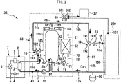
- Fig. 2 is a view showing an example of the circulation path of the heating medium in the first circulation operation of the heating medium circulation system 35 shown in Fig. 1 .
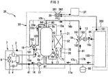
- Fig. 3 is a view showing an example of the circulation path of the heating medium in the second circulation operation of the heating medium circulation system 35 shown in Fig. 1 .
- the first circulation operation will be described.
- the following operation is performed in the first circulation operation in the example shown in Fig. 2 .
- the three-way valve 18 is switched such that the heating medium can flow through the first flow channel 16a.
- the heat pump device 7 and the first circulation pump 12 are operated.
- the heating medium flowing out from the first outlet 8a of the heat storage tank 8 flows into the heat pump device 7 through the fourth flow channel 14.
- the heating medium heated by the heat pump device 7 is supplied to the indoor-heating terminal 100 through the fifth flow channel 15a, the first flow channel 16a, the supply channel 16b, and the supply channel 16c.
- the heating medium having passed through the indoor-heating terminal 100 flows into the heat storage tank 8 from the second return port 8f through the return channel 17a.
- the heating medium circulates through the heat storage tank 8, the fourth flow channel 14, the heat pump device 7, the fifth flow channel 15a, the first flow channel 16a, the supply channel 16b, the supply channel 16c, the indoor-heating terminal 100, the return channel 17a, and the heat storage tank 8 in this order.
- the first circulation operation may be performed in the following manner.
- the control device 36 may control the supply temperature for the indoor-heating terminal 100 by controlling the operation of at least one of the heat pump device 7 and the first circulation pump 12.
- the control device 36 may control the operation of at least one of the heat pump device 7 and the first circulation pump 12 such that the supply temperature detected by the temperature sensor 44 is equal to a target value.
- the user may operate the terminal device 37 to thereby set the target value of the supply temperature.
- the control device 36 may determine the target value of the supply temperature according to the outside air temperature detected by the outside air temperature sensor 2.
- the control device 36 may determine the target value of the supply temperature according to the outside air temperature detected by the room temperature sensor 101.
- the mixing valve 19 is in a state in which the heating medium does not flow through the bypass channel 17b, i.e., a state in which the mixing ratio of the heating medium flowing in from the second inlet 192 is substantially zero.
- the flow rate of the heating medium passing through the first heat exchanger 3 of the heat pump device 7 is equal to the flow rate of the heating medium passing through the indoor-heating terminal 100.
- the heating medium may corrode the first heat exchanger 3.
- an upper limit is set on the flow rate of the heating medium passing through the first heat exchanger 3.
- An example of the upper limit includes 8 L per minute.
- the flow rate of the heating medium passing through the indoor-heating terminal 100 is equal to the flow rate of the heating medium passing through the first heat exchanger 3. Therefore, the upper limit of the flow rate of the heating medium passing through the indoor-heating terminal 100 is equal to the upper limit of the flow rate of the heating medium passing through the first heat exchanger 3.
- the proper supply temperature for the indoor-heating terminal 100 differs depending on the type of the indoor-heating appliance of the indoor-heating terminal 100.
- the indoor-heating terminal 100 includes, e.g., a radiator, a relatively high supply temperature is preferable. Even with the limitation resulting from the upper limit of the flow rate of the heating medium passing through the indoor-heating terminal 100, it becomes possible to output indoor-heating power requested by the user by supplying the heating medium having a relatively high temperature to the indoor-heating terminal 100.
- the second circulation operation will be described.
- the following operation is performed in the second circulation operation in the example shown in Fig. 3 .
- the three-way valve 18 is switched such that the first outlet 182 to which the first flow channel 16a is connected is closed. That is, the three-way valve 18 is switched such that the heating medium can flow through the second flow channel 15b.
- the second circulation pump 13 is operated.
- the heating medium flowing out from the third outlet 8d of the heat storage tank 8 is supplied to the indoor-heating terminal 100 through the third flow channel 10b, the supply channel 16b, and the supply channel 16c.
- the heating medium having passed through the indoor-heating terminal 100 flows through the return channel 17a.
- At least part of the heating medium having passed through the indoor-heating terminal 100 flows into the bypass channel 17b from the branch portion 17c, and flows into the indoor-heating terminal 100 again through the mixing valve 19 and the supply channel 16c.
- the heating medium that has not flowed into the bypass channel 17b at the branch portion 17c flows through the return channel 17a, and flows into the heat storage tank 8 from the second return port 8f.
- the heating medium flows through the heat storage tank 8, the third flow channel 10b, the supply channel 16b, the supply channel 16c, and the indoor-heating terminal 100 in this order.
- Fig. 3 shows a state in which the heat accumulating operation and the second circulation operation are concurrently executed.
- the heat pump device 7 and the first circulation pump 12 are operated in order to perform the heat accumulating operation.
- the second circulation operation may be performed in the following manner.
- the control device 36 may control the flow rate of the heating medium passing through the indoor-heating terminal 100 by controlling the operation of the second circulation pump 13.
- the control device 36 may control the supply temperature for the indoor-heating terminal 100 by controlling the mixing ratio in the mixing valve 19.
- the control device 36 may control the mixing valve 19 such that the supply temperature detected by the temperature sensor 44 is equal to the target value.
- the user may operate the terminal device 37 to thereby set the target value of the supply temperature.
- the control device 36 may determine the target value of the supply temperature according to the outside air temperature detected by the outside air temperature sensor 2.
- the control device 36 may determine the target value of the supply temperature according to the outside air temperature detected by the room temperature sensor 101.
- the limitation resulting from the upper limit of the flow rate of the heating medium passing through the first heat exchanger 3 is not imposed on the flow rate of the heating medium passing through the indoor-heating terminal 100. Consequently, in the second circulation operation, the flow rate of the heating medium passing through the indoor-heating terminal 100 can be made higher than that in the first circulation operation. For example, in the case where the upper limit of the flow rate of the heating medium passing through the first heat exchanger 3 is 8 L per minute, the flow rate of the heating medium passing through the indoor-heating terminal 100 can be made equal to or higher than 9 L per minute in the second circulation operation.
- a relatively low supply temperature is preferable.
- the relatively low supply temperature is, e.g., about 35°C.
- the indoor-heating power requested by the user may not be outputted unless the flow rate of the heating medium passing through the indoor-heating terminal 100 is increased.
- the second circulation operation it is possible to increase the flow rate of the heating medium passing through the indoor-heating terminal 100, and hence it becomes possible to output the indoor-heating power requested by the user even with the relatively low supply temperature.
- the control device 36 may perform control in the following manner in the heat accumulating operation and the second circulation operation.
- the control device 36 may control the operations of the first circulation pump 12 and the second circulation pump 13 such that the flow rate of the heating medium passing through the heat pump device 7 in the heat accumulating operation is not more than the flow rate of the heating medium passing through the indoor-heating terminal 100 in the second circulation operation. With this, the temperature of the heating medium flowing into the heat storage tank 8 from the heat pump device 7 and the supply temperature for the indoor-heating terminal 100 can be set to proper values.
- the control device 36 may control the operation of at least one of the heat pump device 7, the first circulation pump 12, and the mixing valve 19 such that the heat pump outlet temperature detected by the temperature sensor 40 is not less than the supply temperature for the indoor-heating terminal 100.
- the control device 36 may perform control in the above manner in the case where the heat accumulating operation and the second circulation operation are performed concurrently and simultaneously.
- the control device 36 may perform control in the above manner in the case where the heat accumulating operation and the second circulation operation are performed separately and individually at different occasions.
- a configuration may be adopted in which the user can choose the first circulation operation or the second circulation operation according to the type of the indoor-heating terminal 100.
- a configuration may be adopted in which the user can operate the terminal device 37 to thereby preset the execution of the first circulation operation or the second circulation operation in the indoor-heating operation.
- control device 36 may execute only the second circulation operation without executing the heat accumulating operation.
- the following effects can be obtained by providing the first check valve 60 in the third flow channel 10b. It is possible to enable, using a simple device configuration, the second circulation operation in which the heating medium is caused to flow into the supply channel 16b leading to the indoor-heating terminal 100 from the heat storage tank 8, and the first circulation operation in which the heating medium heated by the heat pump device 7 is caused to flow into the supply channel 16b without passing through the heat storage tank 8.
- the first check valve 60 is lower in cost than a flow channel switching valve.
- the first check valve 60 operates automatically, and hence the control device 36 does not need to control the first check valve 60.
- the heating medium circulation system 35 of the present embodiment may execute a circulation heat accumulating operation instead of the above-described once-through heat accumulating operation.
- the following state is established in the circulation heat accumulating operation.
- the total volume of the heating medium passing through the heat pump device 7 in one heat accumulating operation is not less than the capacity of the heat storage tank 8.
- the total volume of the heating medium passing through the heat pump device 7 in one heat accumulating operation may be about several times to ten times the capacity of the heat storage tank 8.
- An increase in the temperature of the heating medium when the heating medium passes through the heat pump device 7 once is small.
- the increase in the temperature thereof in one passage may be 5°C.
- the heating medium in the heat storage tank 8 is heated by the heat pump device 7 a plurality of times, and the temperature of the heating medium increases stepwise and reaches the target temperature.
- the COP can be improved by performing the circulation heat accumulating operation.
- the COP can be improved by reducing an increase in temperature in one passage by performing the circulation heat accumulating operation.
- the control device 36 may perform control in the following manner in the circulation heat accumulating operation and the second circulation operation.
- the control device 36 may control the operations of the first circulation pump 12 and the second circulation pump 13 such that the flow rate of the heating medium passing through the heat pump device 7 in the circulation heat accumulating operation is not more than the flow rate of the heating medium passing through the indoor-heating terminal 100 in the second circulation operation. With this, the COP of the circulation heat accumulating operation can be improved and, at the same time, the supply temperature for the indoor-heating terminal 100 can be set to a proper temperature.
- the control device 36 may perform control in the above manner in the case where the circulation heat accumulating operation and the second circulation operation are executed concurrently and simultaneously.
- the control device 36 may perform control in the above manner in the case where the circulation heat accumulating operation and the second circulation operation are executed separately and individually at different occasions.
- the individual functions of the control device 36 may be implemented by processing circuitry.
- the processing circuitry of the control device 36 may include at least one processor 361 and at least one memory 362.
- the individual functions of the control device 36 may be implemented by software, firmware, or a combination of software and firmware.
- At least one of the software and the firmware may be described as a program.
- At least one of the software and the firmware may be stored in at least one memory 362.
- At least one processor 361 may implement the individual functions of the control device 36 by reading and executing a program stored in at least one memory 362.
- At least one memory 362 may include a non-volatile or volatile semiconductor memory, a magnetic disk, or the like.
- the processing circuitry of the control device 36 may include at least one dedicated hardware.
- the processing circuitry may be, e.g., a single circuit, a composite circuit, a programmed processor, a parallel-programmed processor, an ASIC (Application Specific Integrated Circuit), an FPGA (Field-Programmable Gate Array), or a combination thereof.
- the functions of the individual sections of the control device 36 may be implemented individually by the processing circuitry.
- the functions of the individual sections of the control device 36 may also be implemented collectively by the processing circuitry.
- Part of the individual functions of the control device 36 may be implemented by dedicated hardware, and the other part thereof may be implemented by software or firmware.
- the processing circuitry may implement the individual functions of the control device 36 by using hardware, software, firmware, or a combination thereof.
- the configuration is not limited to the configuration in which the operation of the heating medium circulation system 35 is controlled by a single control device, and a configuration may be adopted in which a plurality of control devices cooperate with each other to control the operation of the heating medium circulation system 35.
Abstract
Description
- The present invention relates to a heating medium circulation system.
- A heat storage hot-water supply and air conditioning device disclosed in
PTL 1 shown below includes a heat storage tank that stores a heating medium that is heated or cooled by a heat pump device, and an air conditioning heat exchanger. The heat storage hot-water supply and air conditioning device is capable of circulating the heating medium from the heat pump device or the heat storage tank to the air conditioning heat exchanger. - [PTL 1] Japanese Patent No.
5253582 - The conventional system described above switches between an operation in which the heating medium is supplied from the heat pump device to the air conditioning heat exchanger and an operation in which the heating medium is supplied from the heat storage tank to the air conditioning heat exchanger using two three-way valves (a heat storage switching valve (19) and a heat discharge switching valve (20)). Consequently, a problem arises in that a device configuration is complicated.
- The present invention has been made in order to solve the above problem, and an object thereof is to provide a heating medium circulation system capable of enabling, using a simple device configuration, an operation in which a heating medium is caused to flow into a supply channel leading to a heat demand section from a heat storage tank, and an operation in which the heating medium heated by heating means is caused to flow into the supply channel without passing through the heat storage tank.
- A heating medium circulation system according to the present invention includes: heating means configured to heat a heating medium; a heat storage tank configured to store the heating medium heated by the heating means; a supply channel through which the heating medium supplied to a heat demand section flows; a first flow channel through which the heating medium flowing out from the heating means is caused to flow into the supply channel without passing through the heat storage tank; a second flow channel through which the heating medium flowing out from the heating means is caused to flow into the heat storage tank; flow channel switching means configured to switch between the first flow channel and the second flow channel; a third flow channel through which the heating medium flowing out from the heat storage tank is caused to flow into the supply channel; and a check valve disposed in the third flow channel.
- According to the heating medium circulation system of the present invention, it becomes possible to enable, using the simple device configuration, the operation in which the heating medium is caused to flow into the supply channel leading to the heat demand section from the heat storage tank, and the operation in which the heating medium heated by the heating means is caused to flow into the supply channel without passing through the heat storage tank.
-
-
Fig. 1 is a view showing a heating medium circulation system according toEmbodiment 1. -
Fig. 2 is a view showing an example of a circulation path of a heating medium in a first circulation operation of the heating medium circulation system shown inFig. 1 . -
Fig. 3 is a view showing an example of a circulation path of the heating medium in a second circulation operation of the heating medium circulation system shown inFig. 1 . - Hereinbelow, an embodiment will be described with reference to the drawings. Common or corresponding elements in the drawings are designated by the same reference numerals, and the duplicate description thereof will be simplified or omitted.
-
Fig. 1 is a view showing a heatingmedium circulation system 35 according to Embodiment 1. As shown inFig. 1 , the heatingmedium circulation system 35 includes aheat pump device 7 and atank unit 33. Theheat pump device 7 is an example of heating means that heats a heating medium. Aheat storage tank 8 is installed inside the casing of thetank unit 33. Theheat storage tank 8 stores the heating medium heated by theheat pump device 7. The heating medium in the present invention may be water. The heating medium in the present invention may also be a fluid heating medium other than water such as, e.g., a calcium chloride aqueous solution, an ethylene glycol aqueous solution, or alcohol. In theheat storage tank 8, a thermal stratification in which the upper side has a high temperature and the lower side has a low temperature can be formed due to a difference in the density of the heating medium caused by a difference in temperature. - The
heat pump device 7 and thetank unit 33 are connected to each other via afourth flow channel 14, afifth flow channel 15a, and electrical wiring (the depiction thereof is omitted). Thetank unit 33 may be installed outdoors or may also be installed indoors. Theheat pump device 7 may be installed outdoors. The heatingmedium circulation system 35 of the present embodiment has a configuration in which theheat pump device 7 and thetank unit 33 are separated from each other. Instead of this configuration, thetank unit 33 may be integrated with theheat pump device 7. - The
heat pump device 7 includes a refrigerant circuit in which acompressor 1, a first heat exchanger 3, adecompression device 4, and asecond heat exchanger 6 are annularly connected byrefrigerant piping 5. A refrigerant sealed in the refrigerant circuit may be, e.g., CO2. Theheat pump device 7 performs an operation of a heat pump cycle using the refrigerant circuit. In the first heat exchanger 3, heat is exchanged between a refrigerant having high temperature and high pressure compressed by thecompressor 1 and the heating medium flowing in from thefourth flow channel 14. Thedecompression device 4 expands the high-pressure refrigerant having passed through the first heat exchanger 3 to turn the high-pressure refrigerant into a low-pressure refrigerant. Thedecompression device 4 may be an expansion valve.
Thesecond heat exchanger 6 causes heat to be exchanged between the low-pressure refrigerant and a fluid. The fluid may be any of, e.g., outside air, groundwater, wastewater, and solar-heated water. Theheat pump device 7 may include a blower or a pump (the depiction thereof is omitted) for sending the fluid to thesecond heat exchanger 6. Theheat pump device 7 in the present embodiment includes an outsideair temperature sensor 2 that detects outside air temperature. - The heating means in the present invention is not limited to the
heat pump device 7. The heating means may also be a combustion heater that performs heating by using heat of combustion of fuel such as gas, kerosene, heavy oil, or coal. The heating means may also be a device that heats the heating medium using solar heat. - A
control device 36 is provided inside thetank unit 33. Valves, pumps, actuators such as thecompressor 1 and the like, and sensors of thetank unit 33 and theheat pump device 7 are electrically connected to thecontrol device 36. Thecontrol device 36 controls various operations described later. - A
terminal device 37 has the function of receiving operations of a user related to change of operation commands and set values. Theterminal device 37 is an example of an operation terminal or a user interface. Thecontrol device 36 and theterminal device 37 are connected to each other so as to be capable of bidirectional data communication by using wired or wireless communication. Theterminal device 37 is equipped with a display section that displays information on the state of the heatingmedium circulation system 35 or the like, an operation section operated by the user such as a switch or the like, a speaker, and a microphone, though the depiction thereof is omitted. Theterminal device 37 may be installed indoors. The heatingmedium circulation system 35 may include a plurality of theterminal devices 37 that are installed at different places. - The
tank unit 33 further includes various components and piping described below in addition to theheat storage tank 8 and thecontrol device 36. A plurality oftank temperature sensors heat storage tank 8 at positions having different heights. Thecontrol device 36 can calculate the amount of stored heat and the amount of a high-temperature heating medium in theheat storage tank 8 by detecting the distribution of the temperature of the heating medium in theheat storage tank 8 using thetank temperature sensors tank temperature sensors heat storage tank 8. - The
control device 36 may control start and stop timings of a heat accumulating operation based on the amount of stored heat in theheat storage tank 8. The heat accumulating operation is the operation in which the heating medium heated by theheat pump device 7 is caused to flow into theheat storage tank 8. - The
heat storage tank 8 includes afirst outlet 8a, aninlet 8b, asecond outlet 8c, athird outlet 8d, afirst return port 8e, and asecond return port 8f. Thefirst outlet 8a, thefirst return port 8e, and thesecond return port 8f are positioned in the lower portion of theheat storage tank 8. Theinlet 8b, thesecond outlet 8c, and thethird outlet 8d are positioned in the upper portion of theheat storage tank 8. - The
fourth flow channel 14 has a first end connected to thefirst outlet 8a of theheat storage tank 8, and a second end connected to the inlet of the heating medium of the first heat exchanger 3 of theheat pump device 7. Afirst circulation pump 12 capable of circulating the heating medium to theheat pump device 7 is connected to some midpoint of thefourth flow channel 14. In the configuration shown in the drawing, thefirst circulation pump 12 is disposed inside thetank unit 33. Instead of this configuration, thefirst circulation pump 12 may be disposed inside theheat pump device 7. Atemperature sensor 41 that detects a heat pump inlet temperature serving as the temperature of the heating medium flowing into theheat pump device 7 is mounted to thefourth flow channel 14. - A three-
way valve 18 includes aninlet 181, afirst outlet 182, and asecond outlet 183. The three-way valve 18 can switch the flow channel between a state in which theinlet 181 is caused to communicate with thefirst outlet 182 and thesecond outlet 183 is closed and a state in which theinlet 181 is caused to communicate with thesecond outlet 183 and thefirst outlet 182 is closed. The three-way valve 18 is an example of flow channel switching means. - The
fifth flow channel 15a has a first end connected to the outlet of the heating medium of the first heat exchanger 3 of theheat pump device 7, and a second end connected to theinlet 181 of the three-way valve 18. Atemperature sensor 40 that detects a heat pump outlet temperature serving as the temperature of the heating medium flowing out from theheat pump device 7 is mounted to thefifth flow channel 15a. Asecond flow channel 15b has a first end connected to thesecond outlet 183 of the three-way valve 18, and a second end connected to theinlet 8b of theheat storage tank 8. - A mixing
valve 19 includes afirst inlet 191, asecond inlet 192, and anoutlet 193. The mixingvalve 19 can cause the heating medium in which the heating medium flowing in from thefirst inlet 191 is mixed with the heating medium flowing in from thesecond inlet 192 to flow out from theoutlet 193. The mixingvalve 19 can adjust a mixing ratio of the heating medium flowing in from thefirst inlet 191 and the heating medium flowing in from thesecond inlet 192. The mixingvalve 19 can also set the mixing ratio of the heating medium flowing in from thesecond inlet 192 to substantially zero. The mixingvalve 19 may also be able to set the mixing ratio of the heating medium flowing in from thefirst inlet 191 to substantially zero. In the configuration shown in the drawing, the mixingvalve 19 is disposed outside thetank unit 33. Instead of this configuration, the mixingvalve 19 may be disposed inside thetank unit 33. - An indoor-
heating terminal 100 heats aroom 200 by releasing heat of the heating medium into theroom 200. The indoor-heating terminal 100 may include, as an indoor-heating appliance, at least one of a floor heating panel installed under a floor, a radiator or a panel heater installed on an indoor wall surface, and a fan convector. In the case where the indoor-heating terminal 100 includes a plurality of the indoor-heating appliances, a method of connecting the indoor-heating appliances may be series connection, parallel connection, or a combination of the series connection and the parallel connection. The indoor-heating terminal 100 is an example of a heat demand section that demands heat. The heatingmedium circulation system 35 of the present embodiment includes aroom temperature sensor 101 that detects the room temperature of theroom 200. - Each of a
supply channel 16b and asupply channel 16c is a flow channel through which the heating medium supplied to the indoor-heating terminal 100 flows. The upstream end of thesupply channel 16b is positioned inside thetank unit 33. The downstream end of thesupply channel 16b is connected to thefirst inlet 191 of the mixingvalve 19. The upstream end of thesupply channel 16c is connected to theoutlet 193 of the mixingvalve 19. The downstream end of thesupply channel 16c is connected to the inlet of the heating medium of the indoor-heating terminal 100. Asecond circulation pump 13 capable of circulating the heating medium to the indoor-heating terminal 100 is connected to some midpoint of thesupply channel 16c. - In the following description, the temperature of the heating medium supplied to the indoor-
heating terminal 100, i.e., the temperature of the heating medium flowing into the indoor-heating terminal 100 is referred to as a "supply temperature". In the present embodiment, the supply temperature can be detected by atemperature sensor 44 disposed in thesupply channel 16c. - A
first flow channel 16a has a first end connected to thefirst outlet 182 of the three-way valve 18, and a second end communicating with the upstream end of thesupply channel 16b. Athird flow channel 10b has a first end connected to thethird outlet 8d of theheat storage tank 8, and a second end communicating with the upstream end of thesupply channel 16b. The confluence of the second end of thefirst flow channel 16a, the second end of thethird flow channel 10b, and the upstream end of thesupply channel 16b forms a T-junction. - The
first flow channel 16a is the flow channel for causing the heating medium flowing out from theheat pump device 7 to flow into thesupply channel 16b without passing through theheat storage tank 8. Thesecond flow channel 15b is the flow channel for causing the heating medium flowing out from theheat pump device 7 to flow into theheat storage tank 8. The three-way valve 18 can switch between a first state in which the heating medium can flow through thefirst flow channel 16a and thesecond flow channel 15b is closed and a second state in which the heating medium can flow through thesecond flow channel 15b and thefirst flow channel 16a is closed. - The
third flow channel 10b is the flow channel for causing the heating medium flowing out from theheat storage tank 8 to flow into thesupply channel 16b. Afirst check valve 60 that prevents backflow is disposed in thethird flow channel 10b. With thefirst check valve 60, it is possible to reliably prevent the heating medium from flowing into theheat storage tank 8 from thefirst flow channel 16a through thethird flow channel 10b. - A
return channel 17a is the flow channel through which the heating medium having passed through the indoor-heating terminal 100 flows. The upstream end of thereturn channel 17a is connected to the outlet of the heating medium of the indoor-heating terminal 100. The downstream end of thereturn channel 17a is connected to thesecond return port 8f of theheat storage tank 8. The heating medium having passed through the indoor-heating terminal 100 is caused to flow into theheat storage tank 8 from thesecond return port 8f through thereturn channel 17a. - A
branch portion 17c is formed at some midpoint of thereturn channel 17a. The upstream end of abypass channel 17b communicates with thereturn channel 17a at thebranch portion 17c. The downstream end of thebypass channel 17b is connected to thesecond inlet 192 of the mixingvalve 19. Thebypass channel 17b is the flow channel for causing the heating medium having passed through the indoor-heating terminal 100 to flow into thesupply channel 16c again without passing through theheat pump device 7 and theheat storage tank 8. It is possible to return at least part of the flow of the heating medium flowing out from the outlet of the indoor-heating terminal 100 to the inlet of the indoor-heating terminal 100 through thebypass channel 17b. - The mixing
valve 19 enables adjustment of the flow rate of the heating medium flowing through thebypass channel 17b. The mixingvalve 19 is an example of flow rate adjustment means that adjusts the flow rate of the heating medium flowing through thebypass channel 17b. - A
second check valve 61 that prevents backflow is disposed in thebypass channel 17b. Thesecond check valve 61 reliably prevents the heating medium in thebypass channel 17b from flowing toward thebranch portion 17c from the mixingvalve 19. - In the present embodiment, a
reservoir tank 90 capable of temporarily storing the heating medium is connected to some midpoint of thereturn channel 17a. In the case where the heating medium in the circuit of the heatingmedium circulation system 35 expands due to temperature, the redundant heating medium can be stored in thereservoir tank 90. - The
tank unit 33 has awater heat exchanger 52. Thewater heat exchanger 52 has a primary-side flow channel through which the heating medium flows, and a secondary-side flow channel through which water flows. Aconduit 10a has a first end connected to thesecond outlet 8c of theheat storage tank 8, and a second end connected to the primary-side inlet of thewater heat exchanger 52. Aconduit 9 has a first end connected to the primary-side outlet of thewater heat exchanger 52, and a second end connected to thefirst return port 8e of theheat storage tank 8. Athird circulation pump 11 capable of circulating the heating medium to thewater heat exchanger 52 is connected to some midpoint of theconduit 9. Aflow rate sensor 71 that detects the flow rate of the heating medium passing through thewater heat exchanger 52 is disposed at some midpoint of theconduit 9. - The downstream end of a
water supply pipe 20 is connected to the secondary-side inlet of thewater heat exchanger 52. The upstream side of thewater supply pipe 20 is connected to a water source such as, e.g., a waterworks. Aflow rate sensor 70 that detects the flow rate of water passing through thewater heat exchanger 52 is disposed at some midpoint of thewater supply pipe 20. The upstream end of a hotwater supply pipe 21 is connected to the secondary-side outlet of thewater heat exchanger 52. The downstream side of the hotwater supply pipe 21 is connected to a hot water supply terminal (the depiction thereof is omitted). The hot water supply terminal may include at least one of, e.g., a faucet, a bathtub, and a shower in a bath. - In the
water heat exchanger 52, heat is exchanged between a high-temperature heating medium supplied from theheat storage tank 8 and water supplied from thewater supply pipe 20. The following operation is performed in a hot water supply operation for supplying hot water to the hotwater supply pipe 21. When the hot water supply terminal on the downstream side of the hotwater supply pipe 21 is opened, water is caused to flow in thewater supply pipe 20, thewater heat exchanger 52, and the hotwater supply pipe 21 due to water pressure of the water source. Thecontrol device 36 can detect whether or not hot water is supplied using theflow rate sensor 70 installed in thewater supply pipe 20. When the start of hot water supply is detected, thecontrol device 36 operates thethird circulation pump 11 to supply the high-temperature heating medium to thewater heat exchanger 52 from the upper portion of theheat storage tank 8. Hot water heated in thewater heat exchanger 52 is supplied to the hot water supply terminal through the hotwater supply pipe 21. The heating medium that is reduced in temperature while it passes through thewater heat exchanger 52 flows into theheat storage tank 8 from thefirst return port 8e through theconduit 9. - The output or the rotation speed of at least one of the
first circulation pump 12, thesecond circulation pump 13, and thethird circulation pump 11 may be variable. At least one of thefirst circulation pump 12, thesecond circulation pump 13, and thethird circulation pump 11 may include a pulse width modulation control DC motor capable of varying the output or the rotation speed in response to a speed command voltage from thecontrol device 36. - In the hot water supply operation, the
control device 36 may control the operation of thethird circulation pump 11 such that the flow rate detected by theflow rate sensor 71 is equal to a predetermined flow rate. In the hot water supply operation, thecontrol device 36 may control the operation of thethird circulation pump 11 such that the temperature of hot water flowing through the hotwater supply pipe 21 is equal to a target value. - The following operation is performed in the heat accumulating operation. The three-
way valve 18 is switched such that the heating medium can flow through thesecond flow channel 15b. Theheat pump device 7 and thefirst circulation pump 12 are operated. The heating medium flowing out from thefirst outlet 8a of theheat storage tank 8 flows into theheat pump device 7 through thefourth flow channel 14. The heating medium heated by theheat pump device 7 flows into theheat storage tank 8 from theinlet 8b through thefifth flow channel 15a and thesecond flow channel 15b. Thus, in the heat accumulating operation, the heating medium circulates through theheat storage tank 8, thefourth flow channel 14, theheat pump device 7, thefifth flow channel 15a, thesecond flow channel 15b, and theheat storage tank 8 in this order. - The
control device 36 can control the heat pump outlet temperature by controlling the operation of at least one of theheat pump device 7 and thefirst circulation pump 12. A user can set hot water temperature by operating theterminal device 37. In the heat accumulating operation, thecontrol device 36 may control the operation of at least one of theheat pump device 7 and thefirst circulation pump 12 such that the heat pump outlet temperature detected by thetemperature sensor 40 is not less than the hot water temperature set by the user. With this, it is possible to set the temperature of the heating medium stored in theheat storage tank 8 to a proper temperature corresponding to the hot water temperature set by the user. - In the heat accumulating operation, it is possible to increase the temperature of a low-temperature heating medium in the lower portion of the
heat storage tank 8 to a target temperature while the low-temperature heating medium passes through theheat pump device 7 once. Hereinafter, such a heat accumulating operation is referred to as a "once-through heat accumulating operation". The once-through heat accumulating operation is enabled by circulating the heating medium at a relatively low flow rate. In the once-through heat accumulating operation, the temperature of the heating medium is increased from, e.g., 20°C to 60°C while the heating medium passes through theheat pump device 7 once. By performing the once-through heat accumulating operation, the layer of the heated high-temperature heating medium and the layer of the low-temperature heating medium that is not heated yet can be stacked on each other in theheat storage tank 8. - In the case where the
heat pump device 7 has a CO2 refrigerant, a COP (Coefficient Of Performance), i.e., energy efficiency is improved by performing the once-through heat accumulating operation. - As an indoor-heating operation for heating the
room 200, the heatingmedium circulation system 35 of the present embodiment can execute two types of the indoor-heating operations that are a first circulation operation and a second circulation operation.Fig. 2 is a view showing an example of the circulation path of the heating medium in the first circulation operation of the heatingmedium circulation system 35 shown inFig. 1 .Fig. 3 is a view showing an example of the circulation path of the heating medium in the second circulation operation of the heatingmedium circulation system 35 shown inFig. 1 . - First, the first circulation operation will be described. The following operation is performed in the first circulation operation in the example shown in
Fig. 2 . The three-way valve 18 is switched such that the heating medium can flow through thefirst flow channel 16a. Theheat pump device 7 and thefirst circulation pump 12 are operated. The heating medium flowing out from thefirst outlet 8a of theheat storage tank 8 flows into theheat pump device 7 through thefourth flow channel 14. The heating medium heated by theheat pump device 7 is supplied to the indoor-heating terminal 100 through thefifth flow channel 15a, thefirst flow channel 16a, thesupply channel 16b, and thesupply channel 16c. The heating medium having passed through the indoor-heating terminal 100 flows into theheat storage tank 8 from thesecond return port 8f through thereturn channel 17a. Thus, in the first circulation operation, the heating medium circulates through theheat storage tank 8, thefourth flow channel 14, theheat pump device 7, thefifth flow channel 15a, thefirst flow channel 16a, thesupply channel 16b, thesupply channel 16c, the indoor-heating terminal 100, thereturn channel 17a, and theheat storage tank 8 in this order. - The first circulation operation may be performed in the following manner. The
control device 36 may control the supply temperature for the indoor-heating terminal 100 by controlling the operation of at least one of theheat pump device 7 and thefirst circulation pump 12. Thecontrol device 36 may control the operation of at least one of theheat pump device 7 and thefirst circulation pump 12 such that the supply temperature detected by thetemperature sensor 44 is equal to a target value. The user may operate theterminal device 37 to thereby set the target value of the supply temperature. Thecontrol device 36 may determine the target value of the supply temperature according to the outside air temperature detected by the outsideair temperature sensor 2. Thecontrol device 36 may determine the target value of the supply temperature according to the outside air temperature detected by theroom temperature sensor 101. - The following state is established in the first circulation operation in the example shown in
Fig. 2 . The mixingvalve 19 is in a state in which the heating medium does not flow through thebypass channel 17b, i.e., a state in which the mixing ratio of the heating medium flowing in from thesecond inlet 192 is substantially zero. The flow rate of the heating medium passing through the first heat exchanger 3 of theheat pump device 7 is equal to the flow rate of the heating medium passing through the indoor-heating terminal 100. - When the velocity of flow of the heating medium flowing in the first heat exchanger 3 exceeds a given threshold value, the heating medium may corrode the first heat exchanger 3. In order to reliably prevent the corrosion of the first heat exchanger 3, there are cases where an upper limit is set on the flow rate of the heating medium passing through the first heat exchanger 3. An example of the upper limit includes 8 L per minute.
- In the example shown in
Fig. 2 , the flow rate of the heating medium passing through the indoor-heating terminal 100 is equal to the flow rate of the heating medium passing through the first heat exchanger 3. Therefore, the upper limit of the flow rate of the heating medium passing through the indoor-heating terminal 100 is equal to the upper limit of the flow rate of the heating medium passing through the first heat exchanger 3. - There are cases where the proper supply temperature for the indoor-
heating terminal 100 differs depending on the type of the indoor-heating appliance of the indoor-heating terminal 100. In the case where the indoor-heating terminal 100 includes, e.g., a radiator, a relatively high supply temperature is preferable. Even with the limitation resulting from the upper limit of the flow rate of the heating medium passing through the indoor-heating terminal 100, it becomes possible to output indoor-heating power requested by the user by supplying the heating medium having a relatively high temperature to the indoor-heating terminal 100. - Next, the second circulation operation will be described. The following operation is performed in the second circulation operation in the example shown in
Fig. 3 . The three-way valve 18 is switched such that thefirst outlet 182 to which thefirst flow channel 16a is connected is closed. That is, the three-way valve 18 is switched such that the heating medium can flow through thesecond flow channel 15b. Thesecond circulation pump 13 is operated. The heating medium flowing out from thethird outlet 8d of theheat storage tank 8 is supplied to the indoor-heating terminal 100 through thethird flow channel 10b, thesupply channel 16b, and thesupply channel 16c. The heating medium having passed through the indoor-heating terminal 100 flows through thereturn channel 17a. At least part of the heating medium having passed through the indoor-heating terminal 100 flows into thebypass channel 17b from thebranch portion 17c, and flows into the indoor-heating terminal 100 again through the mixingvalve 19 and thesupply channel 16c. The heating medium that has not flowed into thebypass channel 17b at thebranch portion 17c flows through thereturn channel 17a, and flows into theheat storage tank 8 from thesecond return port 8f. Thus, in the second circulation operation, the heating medium flows through theheat storage tank 8, thethird flow channel 10b, thesupply channel 16b, thesupply channel 16c, and the indoor-heating terminal 100 in this order. - In the present embodiment, the heat accumulating operation described above and the second circulation operation can be executed concurrently and simultaneously. With this, the advantage is achieved that the second circulation operation can be executed even in the case where the amount of stored heat in the
heat storage tank 8 is insufficient.Fig. 3 shows a state in which the heat accumulating operation and the second circulation operation are concurrently executed. InFig. 3 , theheat pump device 7 and thefirst circulation pump 12 are operated in order to perform the heat accumulating operation. - The second circulation operation may be performed in the following manner. The
control device 36 may control the flow rate of the heating medium passing through the indoor-heating terminal 100 by controlling the operation of thesecond circulation pump 13. Thecontrol device 36 may control the supply temperature for the indoor-heating terminal 100 by controlling the mixing ratio in the mixingvalve 19. Thecontrol device 36 may control the mixingvalve 19 such that the supply temperature detected by thetemperature sensor 44 is equal to the target value. The user may operate theterminal device 37 to thereby set the target value of the supply temperature. Thecontrol device 36 may determine the target value of the supply temperature according to the outside air temperature detected by the outsideair temperature sensor 2. Thecontrol device 36 may determine the target value of the supply temperature according to the outside air temperature detected by theroom temperature sensor 101. - According to the second circulation operation, the limitation resulting from the upper limit of the flow rate of the heating medium passing through the first heat exchanger 3 is not imposed on the flow rate of the heating medium passing through the indoor-
heating terminal 100. Consequently, in the second circulation operation, the flow rate of the heating medium passing through the indoor-heating terminal 100 can be made higher than that in the first circulation operation. For example, in the case where the upper limit of the flow rate of the heating medium passing through the first heat exchanger 3 is 8 L per minute, the flow rate of the heating medium passing through the indoor-heating terminal 100 can be made equal to or higher than 9 L per minute in the second circulation operation. - For example, in the case where the indoor-
heating terminal 100 includes an appliance for floor heating, a relatively low supply temperature is preferable. The relatively low supply temperature is, e.g., about 35°C. In the case where the supply temperature is relatively low, as compared with the case where the supply temperature is relatively high, the indoor-heating power requested by the user may not be outputted unless the flow rate of the heating medium passing through the indoor-heating terminal 100 is increased. According to the second circulation operation, it is possible to increase the flow rate of the heating medium passing through the indoor-heating terminal 100, and hence it becomes possible to output the indoor-heating power requested by the user even with the relatively low supply temperature. - The
control device 36 may perform control in the following manner in the heat accumulating operation and the second circulation operation. Thecontrol device 36 may control the operations of thefirst circulation pump 12 and thesecond circulation pump 13 such that the flow rate of the heating medium passing through theheat pump device 7 in the heat accumulating operation is not more than the flow rate of the heating medium passing through the indoor-heating terminal 100 in the second circulation operation. With this, the temperature of the heating medium flowing into theheat storage tank 8 from theheat pump device 7 and the supply temperature for the indoor-heating terminal 100 can be set to proper values. Thecontrol device 36 may control the operation of at least one of theheat pump device 7, thefirst circulation pump 12, and the mixingvalve 19 such that the heat pump outlet temperature detected by thetemperature sensor 40 is not less than the supply temperature for the indoor-heating terminal 100. With this, it is possible to reliably prevent the heating medium having a temperature lower than the supply temperature for the indoor-heating terminal 100 from flowing into theheat storage tank 8 from theheat pump device 7. Thecontrol device 36 may perform control in the above manner in the case where the heat accumulating operation and the second circulation operation are performed concurrently and simultaneously. Thecontrol device 36 may perform control in the above manner in the case where the heat accumulating operation and the second circulation operation are performed separately and individually at different occasions. - A configuration may be adopted in which the user can choose the first circulation operation or the second circulation operation according to the type of the indoor-
heating terminal 100. For example, a configuration may be adopted in which the user can operate theterminal device 37 to thereby preset the execution of the first circulation operation or the second circulation operation in the indoor-heating operation. - For example, in the case where the amount of stored heat in the
heat storage tank 8 is sufficient, thecontrol device 36 may execute only the second circulation operation without executing the heat accumulating operation. - According to the present embodiment, the following effects can be obtained by providing the
first check valve 60 in thethird flow channel 10b. It is possible to enable, using a simple device configuration, the second circulation operation in which the heating medium is caused to flow into thesupply channel 16b leading to the indoor-heating terminal 100 from theheat storage tank 8, and the first circulation operation in which the heating medium heated by theheat pump device 7 is caused to flow into thesupply channel 16b without passing through theheat storage tank 8. Thefirst check valve 60 is lower in cost than a flow channel switching valve. Thefirst check valve 60 operates automatically, and hence thecontrol device 36 does not need to control thefirst check valve 60. - The heating
medium circulation system 35 of the present embodiment may execute a circulation heat accumulating operation instead of the above-described once-through heat accumulating operation. The following state is established in the circulation heat accumulating operation. The total volume of the heating medium passing through theheat pump device 7 in one heat accumulating operation is not less than the capacity of theheat storage tank 8. For example, the total volume of the heating medium passing through theheat pump device 7 in one heat accumulating operation may be about several times to ten times the capacity of theheat storage tank 8. An increase in the temperature of the heating medium when the heating medium passes through theheat pump device 7 once is small. For example, the increase in the temperature thereof in one passage may be 5°C. The heating medium in theheat storage tank 8 is heated by the heat pump device 7 a plurality of times, and the temperature of the heating medium increases stepwise and reaches the target temperature. - Depending on the type of the refrigerant of the
heat pump device 7, the COP can be improved by performing the circulation heat accumulating operation. For example, in the case where theheat pump 7 has R410A as the refrigerant, the COP can be improved by reducing an increase in temperature in one passage by performing the circulation heat accumulating operation. - The
control device 36 may perform control in the following manner in the circulation heat accumulating operation and the second circulation operation. Thecontrol device 36 may control the operations of thefirst circulation pump 12 and thesecond circulation pump 13 such that the flow rate of the heating medium passing through theheat pump device 7 in the circulation heat accumulating operation is not more than the flow rate of the heating medium passing through the indoor-heating terminal 100 in the second circulation operation. With this, the COP of the circulation heat accumulating operation can be improved and, at the same time, the supply temperature for the indoor-heating terminal 100 can be set to a proper temperature. Thecontrol device 36 may perform control in the above manner in the case where the circulation heat accumulating operation and the second circulation operation are executed concurrently and simultaneously. Thecontrol device 36 may perform control in the above manner in the case where the circulation heat accumulating operation and the second circulation operation are executed separately and individually at different occasions. - The individual functions of the
control device 36 may be implemented by processing circuitry. The processing circuitry of thecontrol device 36 may include at least oneprocessor 361 and at least onememory 362. In the case where the processing circuitry includes at least oneprocessor 361 and at least onememory 362, the individual functions of thecontrol device 36 may be implemented by software, firmware, or a combination of software and firmware. At least one of the software and the firmware may be described as a program. At least one of the software and the firmware may be stored in at least onememory 362. At least oneprocessor 361 may implement the individual functions of thecontrol device 36 by reading and executing a program stored in at least onememory 362. At least onememory 362 may include a non-volatile or volatile semiconductor memory, a magnetic disk, or the like. - The processing circuitry of the
control device 36 may include at least one dedicated hardware. In the case where the processing circuitry includes at least one dedicated hardware, the processing circuitry may be, e.g., a single circuit, a composite circuit, a programmed processor, a parallel-programmed processor, an ASIC (Application Specific Integrated Circuit), an FPGA (Field-Programmable Gate Array), or a combination thereof. The functions of the individual sections of thecontrol device 36 may be implemented individually by the processing circuitry. In addition, the functions of the individual sections of thecontrol device 36 may also be implemented collectively by the processing circuitry. Part of the individual functions of thecontrol device 36 may be implemented by dedicated hardware, and the other part thereof may be implemented by software or firmware. The processing circuitry may implement the individual functions of thecontrol device 36 by using hardware, software, firmware, or a combination thereof. - The configuration is not limited to the configuration in which the operation of the heating
medium circulation system 35 is controlled by a single control device, and a configuration may be adopted in which a plurality of control devices cooperate with each other to control the operation of the heatingmedium circulation system 35. -
- 1
- compressor
- 2
- outside air temperature sensor
- 3
- first heat exchanger
- 4
- decompression device
- 5
- refrigerant piping
- 6
- second heat exchanger
- 7
- heat pump device
- 8
- heat storage tank
- 10b
- third flow channel
- 11
- third circulation pump
- 12
- first circulation pump
- 13
- second circulation pump
- 14
- fourth flow channel
- 15a
- fifth flow channel
- 15b
- second flow channel
- 16a
- first flow channel
- 16b,16c
- supply channel
- 17a
- return channel
- 17b
- bypass channel
- 18
- three-way valve
- 19
- mixing valve
- 33
- tank unit
- 35
- heating medium circulation system
- 36
- control device
- 37
- terminal device
- 60
- first check valve
- 61
- second check valve
- 100
- indoor-heating terminal
- 101
- room temperature sensor
Claims (9)
- A heating medium circulation system comprising:heating means configured to heat a heating medium;a heat storage tank configured to store the heating medium heated by the heating means;a supply channel through which the heating medium supplied to a heat demand section flows;a first flow channel through which the heating medium flowing out from the heating means is caused to flow into the supply channel without passing through the heat storage tank;a second flow channel through which the heating medium flowing out from the heating means is caused to flow into the heat storage tank;flow channel switching means configured to switch between the first flow channel and the second flow channel;a third flow channel through which the heating medium flowing out from the heat storage tank is caused to flow into the supply channel; anda check valve disposed in the third flow channel.
- The heating medium circulation system according to Claim 1, further comprising:
means configured to control a first circulation operation in which the heating medium flows through the heating means, the first flow channel, and the supply channel in this order, and a second circulation operation in which the heating medium flows through the heat storage tank, the third flow channel, and the supply channel in this order. - The heating medium circulation system according to Claim 2, wherein
the flow channel switching means switches to the first flow channel, and the heating medium heated by the heating means flows into the supply channel without passing through the heat storage tank in the first circulation operation. - The heating medium circulation system according to Claim 2 or 3, further comprising:a bypass channel through which the heating medium having passed through the heat demand section is caused to flow into the supply channel without passing through the heating means and the heat storage tank; andflow rate adjustment means configured to adjust a flow rate of the heating medium flowing through the bypass channel.
- The heating medium circulation system according to any one of Claims 2 to 4, further comprising:a fourth flow channel through which the heating medium flowing out from the heat storage tank is caused to flow into the heating means; anda return channel through which the heating medium having passed through the heat demand section is caused to flow into the heat storage tank, whereinthe heating medium circulates through the heat storage tank, the third flow channel, the supply channel, the heat demand section, the return channel, and the heat storage tank in this order in the second circulation operation, anda heat accumulating operation in which the heating medium circulates through the heat storage tank, the fourth flow channel, the heating means, the second flow channel, and the heat storage tank in this order, and the second circulation operation are concurrently executable.
- The heating medium circulation system according to any one of Claims 2 to 5, further comprising:
means configured to perform control such that a temperature of the heating medium flowing out from the heating means in a heat accumulating operation in which the heating medium heated by the heating means is caused to flow into the heat storage tank is not less than a hot water supply temperature set by a user. - The heating medium circulation system according to any one of Claims 2 to 6, further comprising:
means configured to perform control such that a temperature of the heating medium flowing out from the heating means in a heat accumulating operation in which the heating medium heated by the heating means is caused to flow into the heat storage tank is not less than a temperature of the heating medium supplied to the heat demand section in the second circulation operation. - The heating medium circulation system according to any one of Claims 2 to 7, further comprising:
means configured to perform control such that a flow rate of the heating medium passing through the heating means in a heat accumulating operation in which the heating medium heated by the heating means is caused to flow into the heat storage tank is not more than a flow rate of the heating medium passing through the heat demand section in the second circulation operation. - The heating medium circulation system according to any one of Claims 2 to 7, further comprising:
means configured to perform control such that a flow rate of the heating medium passing through the heating means in a circulation heat accumulating operation in which a total volume of the heating medium having passed through the heating means in one heat accumulating operation is not less than a capacity of the heat storage tank is not less than a flow rate of the heating medium passing through the heat demand section in the second circulation operation.
Applications Claiming Priority (1)
| Application Number | Priority Date | Filing Date | Title |
|---|---|---|---|
| PCT/JP2016/083414 WO2018087867A1 (en) | 2016-11-10 | 2016-11-10 | Heating medium circulation system |
Publications (3)
| Publication Number | Publication Date |
|---|---|
| EP3540324A1 true EP3540324A1 (en) | 2019-09-18 |
| EP3540324A4 EP3540324A4 (en) | 2019-11-13 |
| EP3540324B1 EP3540324B1 (en) | 2021-03-10 |
Family
ID=62109456
Family Applications (1)
| Application Number | Title | Priority Date | Filing Date |
|---|---|---|---|
| EP16921139.8A Active EP3540324B1 (en) | 2016-11-10 | 2016-11-10 | Heating medium circulation system |
Country Status (2)
| Country | Link |
|---|---|
| EP (1) | EP3540324B1 (en) |
| WO (1) | WO2018087867A1 (en) |
Cited By (2)
| Publication number | Priority date | Publication date | Assignee | Title |
|---|---|---|---|---|
| CN112855293A (en) * | 2021-01-19 | 2021-05-28 | 西安交通大学 | Integrated heat storage industrial steam supply cogeneration peak shaving frequency modulation system and operation method |
| EP3910249A1 (en) * | 2020-05-13 | 2021-11-17 | Commissariat à l'Energie Atomique et aux Energies Alternatives | System for producing and distributing heat and cold and method for managing same |
Family Cites Families (9)
| Publication number | Priority date | Publication date | Assignee | Title |
|---|---|---|---|---|
| JP2008256346A (en) * | 2007-03-14 | 2008-10-23 | Matsushita Electric Ind Co Ltd | Heat pump device |
| EP2077423A1 (en) * | 2008-01-02 | 2009-07-08 | Esbe Ab | Regulation of flow temperature of a liquid in a heating circuit |
| JP5253582B2 (en) * | 2009-09-29 | 2013-07-31 | 三菱電機株式会社 | Thermal storage hot water supply air conditioner |
| JP2011257105A (en) * | 2010-06-11 | 2011-12-22 | Tokyo Electric Power Co Inc:The | Hot-water storage type water heater |
| JP5655695B2 (en) * | 2011-05-11 | 2015-01-21 | 三菱電機株式会社 | Hot water storage water heater |
| JP5838914B2 (en) * | 2012-05-29 | 2016-01-06 | 三菱電機株式会社 | Hot water storage water heater |
| JP5581361B2 (en) * | 2012-09-24 | 2014-08-27 | リンナイ株式会社 | Heating device and water heater |
| EP3220061B1 (en) * | 2014-11-10 | 2020-07-08 | Mitsubishi Electric Corporation | Fluid circulation system |
| JP6464873B2 (en) * | 2015-03-26 | 2019-02-06 | 三菱電機株式会社 | Hot water storage type heat pump water heater |
-
2016
- 2016-11-10 EP EP16921139.8A patent/EP3540324B1/en active Active
- 2016-11-10 WO PCT/JP2016/083414 patent/WO2018087867A1/en unknown
Cited By (4)
| Publication number | Priority date | Publication date | Assignee | Title |
|---|---|---|---|---|
| EP3910249A1 (en) * | 2020-05-13 | 2021-11-17 | Commissariat à l'Energie Atomique et aux Energies Alternatives | System for producing and distributing heat and cold and method for managing same |
| FR3110217A1 (en) * | 2020-05-13 | 2021-11-19 | Commissariat A L'energie Atomique Et Aux Energies Alternatives | Heat and cold production and distribution system and its management process |
| CN112855293A (en) * | 2021-01-19 | 2021-05-28 | 西安交通大学 | Integrated heat storage industrial steam supply cogeneration peak shaving frequency modulation system and operation method |
| CN112855293B (en) * | 2021-01-19 | 2022-03-22 | 西安交通大学 | Integrated heat storage industrial steam supply cogeneration peak shaving frequency modulation system and operation method |
Also Published As
| Publication number | Publication date |
|---|---|
| EP3540324A4 (en) | 2019-11-13 |
| WO2018087867A1 (en) | 2018-05-17 |
| EP3540324B1 (en) | 2021-03-10 |
Similar Documents
| Publication | Publication Date | Title |
|---|---|---|
| US11162627B2 (en) | Controller, method of operating a water source heat pump and a water source heat pump | |
| US10697648B2 (en) | Heating and hot water supply system | |
| KR101222331B1 (en) | Heat-pump hot water apparatus | |
| JP6515859B2 (en) | Hot water storage system | |
| US10401038B2 (en) | Heat pump system | |
| EP3199884B1 (en) | Hot-water supply and heating system | |
| CN107763726B (en) | heat pump system | |
| US20150052914A1 (en) | System and Method for Using an Electronic Expansion Valve to Control a Discharge Pressure in a Multi-Purpose HVAC System | |
| EP3540324A1 (en) | Heating medium circulation system | |
| EP3258185B1 (en) | Heat supply system | |
| JP6012530B2 (en) | Hot water storage water heater | |
| JP6645593B2 (en) | Heat medium circulation system | |
| KR20150035012A (en) | Heat Storaging Type Heat Pump Boiler System | |
| JP6888738B2 (en) | Heating system | |
| JP2012180962A (en) | Water heater system having hot water storage tank with auxiliary heat source | |
| WO2017163305A1 (en) | Heat medium circulation system | |
| EP3220061B1 (en) | Fluid circulation system | |
| JP6687156B2 (en) | Heat medium supply system | |
| KR101610958B1 (en) | Water circulation system associated with refrigerant cycle and the method of controlling the same | |
| CN112344430B (en) | Control method of heating and hot water supply system | |
| JP2017067327A (en) | Hot water heating device | |
| JP6119672B2 (en) | Hot water storage water heater | |
| KR101875226B1 (en) | A hot water circulation system associated with heat pump and a control method the same | |
| JP2023064884A (en) | Hot water storage type hot water supply device | |
| KR20090019254A (en) | Co-generation |
Legal Events
| Date | Code | Title | Description |
|---|---|---|---|
| STAA | Information on the status of an ep patent application or granted ep patent |
Free format text: STATUS: THE INTERNATIONAL PUBLICATION HAS BEEN MADE |
|
| PUAI | Public reference made under article 153(3) epc to a published international application that has entered the european phase |
Free format text: ORIGINAL CODE: 0009012 |
|
| STAA | Information on the status of an ep patent application or granted ep patent |
Free format text: STATUS: REQUEST FOR EXAMINATION WAS MADE |
|
| 17P | Request for examination filed |
Effective date: 20190219 |
|
| AK | Designated contracting states |
Kind code of ref document: A1 Designated state(s): AL AT BE BG CH CY CZ DE DK EE ES FI FR GB GR HR HU IE IS IT LI LT LU LV MC MK MT NL NO PL PT RO RS SE SI SK SM TR |
|
| AX | Request for extension of the european patent |
Extension state: BA ME |
|
| A4 | Supplementary search report drawn up and despatched |
Effective date: 20191011 |
|
| RIC1 | Information provided on ipc code assigned before grant |
Ipc: F24D 11/00 20060101ALI20191007BHEP Ipc: F24H 1/18 20060101AFI20191007BHEP Ipc: F24D 19/10 20060101ALI20191007BHEP Ipc: F24D 3/08 20060101ALI20191007BHEP Ipc: F24H 4/02 20060101ALI20191007BHEP Ipc: F24D 11/02 20060101ALI20191007BHEP |
|
| DAV | Request for validation of the european patent (deleted) | ||
| DAX | Request for extension of the european patent (deleted) | ||
| STAA | Information on the status of an ep patent application or granted ep patent |
Free format text: STATUS: EXAMINATION IS IN PROGRESS |
|
| 17Q | First examination report despatched |
Effective date: 20200414 |
|
| GRAP | Despatch of communication of intention to grant a patent |
Free format text: ORIGINAL CODE: EPIDOSNIGR1 |
|
| STAA | Information on the status of an ep patent application or granted ep patent |
Free format text: STATUS: GRANT OF PATENT IS INTENDED |
|
| INTG | Intention to grant announced |
Effective date: 20201005 |
|
| GRAS | Grant fee paid |
Free format text: ORIGINAL CODE: EPIDOSNIGR3 |
|
| STAA | Information on the status of an ep patent application or granted ep patent |
Free format text: STATUS: GRANT OF PATENT IS INTENDED |
|
| GRAA | (expected) grant |
Free format text: ORIGINAL CODE: 0009210 |
|
| STAA | Information on the status of an ep patent application or granted ep patent |
Free format text: STATUS: THE PATENT HAS BEEN GRANTED |
|
| AK | Designated contracting states |
Kind code of ref document: B1 Designated state(s): AL AT BE BG CH CY CZ DE DK EE ES FI FR GB GR HR HU IE IS IT LI LT LU LV MC MK MT NL NO PL PT RO RS SE SI SK SM TR |
|
| REG | Reference to a national code |
Ref country code: GB Ref legal event code: FG4D |
|
| REG | Reference to a national code |
Ref country code: AT Ref legal event code: REF Ref document number: 1370240 Country of ref document: AT Kind code of ref document: T Effective date: 20210315 Ref country code: CH Ref legal event code: EP |
|
| REG | Reference to a national code |
Ref country code: IE Ref legal event code: FG4D |
|
| REG | Reference to a national code |
Ref country code: DE Ref legal event code: R096 Ref document number: 602016054281 Country of ref document: DE |
|
| REG | Reference to a national code |
Ref country code: SE Ref legal event code: TRGR |
|
| REG | Reference to a national code |
Ref country code: LT Ref legal event code: MG9D |
|
| PG25 | Lapsed in a contracting state [announced via postgrant information from national office to epo] |
Ref country code: LT Free format text: LAPSE BECAUSE OF FAILURE TO SUBMIT A TRANSLATION OF THE DESCRIPTION OR TO PAY THE FEE WITHIN THE PRESCRIBED TIME-LIMIT Effective date: 20210310 Ref country code: BG Free format text: LAPSE BECAUSE OF FAILURE TO SUBMIT A TRANSLATION OF THE DESCRIPTION OR TO PAY THE FEE WITHIN THE PRESCRIBED TIME-LIMIT Effective date: 20210610 Ref country code: NO Free format text: LAPSE BECAUSE OF FAILURE TO SUBMIT A TRANSLATION OF THE DESCRIPTION OR TO PAY THE FEE WITHIN THE PRESCRIBED TIME-LIMIT Effective date: 20210610 Ref country code: HR Free format text: LAPSE BECAUSE OF FAILURE TO SUBMIT A TRANSLATION OF THE DESCRIPTION OR TO PAY THE FEE WITHIN THE PRESCRIBED TIME-LIMIT Effective date: 20210310 Ref country code: FI Free format text: LAPSE BECAUSE OF FAILURE TO SUBMIT A TRANSLATION OF THE DESCRIPTION OR TO PAY THE FEE WITHIN THE PRESCRIBED TIME-LIMIT Effective date: 20210310 Ref country code: GR Free format text: LAPSE BECAUSE OF FAILURE TO SUBMIT A TRANSLATION OF THE DESCRIPTION OR TO PAY THE FEE WITHIN THE PRESCRIBED TIME-LIMIT Effective date: 20210611 |
|
| REG | Reference to a national code |
Ref country code: AT Ref legal event code: MK05 Ref document number: 1370240 Country of ref document: AT Kind code of ref document: T Effective date: 20210310 |
|
| REG | Reference to a national code |
Ref country code: NL Ref legal event code: MP Effective date: 20210310 |
|
| PG25 | Lapsed in a contracting state [announced via postgrant information from national office to epo] |
Ref country code: RS Free format text: LAPSE BECAUSE OF FAILURE TO SUBMIT A TRANSLATION OF THE DESCRIPTION OR TO PAY THE FEE WITHIN THE PRESCRIBED TIME-LIMIT Effective date: 20210310 Ref country code: LV Free format text: LAPSE BECAUSE OF FAILURE TO SUBMIT A TRANSLATION OF THE DESCRIPTION OR TO PAY THE FEE WITHIN THE PRESCRIBED TIME-LIMIT Effective date: 20210310 |
|
| PG25 | Lapsed in a contracting state [announced via postgrant information from national office to epo] |
Ref country code: NL Free format text: LAPSE BECAUSE OF FAILURE TO SUBMIT A TRANSLATION OF THE DESCRIPTION OR TO PAY THE FEE WITHIN THE PRESCRIBED TIME-LIMIT Effective date: 20210310 |
|
| PG25 | Lapsed in a contracting state [announced via postgrant information from national office to epo] |
Ref country code: EE Free format text: LAPSE BECAUSE OF FAILURE TO SUBMIT A TRANSLATION OF THE DESCRIPTION OR TO PAY THE FEE WITHIN THE PRESCRIBED TIME-LIMIT Effective date: 20210310 Ref country code: CZ Free format text: LAPSE BECAUSE OF FAILURE TO SUBMIT A TRANSLATION OF THE DESCRIPTION OR TO PAY THE FEE WITHIN THE PRESCRIBED TIME-LIMIT Effective date: 20210310 Ref country code: AT Free format text: LAPSE BECAUSE OF FAILURE TO SUBMIT A TRANSLATION OF THE DESCRIPTION OR TO PAY THE FEE WITHIN THE PRESCRIBED TIME-LIMIT Effective date: 20210310 Ref country code: SM Free format text: LAPSE BECAUSE OF FAILURE TO SUBMIT A TRANSLATION OF THE DESCRIPTION OR TO PAY THE FEE WITHIN THE PRESCRIBED TIME-LIMIT Effective date: 20210310 |
|
| PG25 | Lapsed in a contracting state [announced via postgrant information from national office to epo] |
Ref country code: IS Free format text: LAPSE BECAUSE OF FAILURE TO SUBMIT A TRANSLATION OF THE DESCRIPTION OR TO PAY THE FEE WITHIN THE PRESCRIBED TIME-LIMIT Effective date: 20210710 Ref country code: SK Free format text: LAPSE BECAUSE OF FAILURE TO SUBMIT A TRANSLATION OF THE DESCRIPTION OR TO PAY THE FEE WITHIN THE PRESCRIBED TIME-LIMIT Effective date: 20210310 Ref country code: RO Free format text: LAPSE BECAUSE OF FAILURE TO SUBMIT A TRANSLATION OF THE DESCRIPTION OR TO PAY THE FEE WITHIN THE PRESCRIBED TIME-LIMIT Effective date: 20210310 Ref country code: PT Free format text: LAPSE BECAUSE OF FAILURE TO SUBMIT A TRANSLATION OF THE DESCRIPTION OR TO PAY THE FEE WITHIN THE PRESCRIBED TIME-LIMIT Effective date: 20210712 Ref country code: PL Free format text: LAPSE BECAUSE OF FAILURE TO SUBMIT A TRANSLATION OF THE DESCRIPTION OR TO PAY THE FEE WITHIN THE PRESCRIBED TIME-LIMIT Effective date: 20210310 |
|
| REG | Reference to a national code |
Ref country code: DE Ref legal event code: R097 Ref document number: 602016054281 Country of ref document: DE |
|
| PLBE | No opposition filed within time limit |
Free format text: ORIGINAL CODE: 0009261 |
|
| STAA | Information on the status of an ep patent application or granted ep patent |
Free format text: STATUS: NO OPPOSITION FILED WITHIN TIME LIMIT |
|
| PG25 | Lapsed in a contracting state [announced via postgrant information from national office to epo] |
Ref country code: ES Free format text: LAPSE BECAUSE OF FAILURE TO SUBMIT A TRANSLATION OF THE DESCRIPTION OR TO PAY THE FEE WITHIN THE PRESCRIBED TIME-LIMIT Effective date: 20210310 Ref country code: DK Free format text: LAPSE BECAUSE OF FAILURE TO SUBMIT A TRANSLATION OF THE DESCRIPTION OR TO PAY THE FEE WITHIN THE PRESCRIBED TIME-LIMIT Effective date: 20210310 Ref country code: AL Free format text: LAPSE BECAUSE OF FAILURE TO SUBMIT A TRANSLATION OF THE DESCRIPTION OR TO PAY THE FEE WITHIN THE PRESCRIBED TIME-LIMIT Effective date: 20210310 |
|
| 26N | No opposition filed |
Effective date: 20211213 |
|
| PG25 | Lapsed in a contracting state [announced via postgrant information from national office to epo] |
Ref country code: SI Free format text: LAPSE BECAUSE OF FAILURE TO SUBMIT A TRANSLATION OF THE DESCRIPTION OR TO PAY THE FEE WITHIN THE PRESCRIBED TIME-LIMIT Effective date: 20210310 |
|
| PG25 | Lapsed in a contracting state [announced via postgrant information from national office to epo] |
Ref country code: IT Free format text: LAPSE BECAUSE OF FAILURE TO SUBMIT A TRANSLATION OF THE DESCRIPTION OR TO PAY THE FEE WITHIN THE PRESCRIBED TIME-LIMIT Effective date: 20210310 |
|
| PG25 | Lapsed in a contracting state [announced via postgrant information from national office to epo] |
Ref country code: IS Free format text: LAPSE BECAUSE OF FAILURE TO SUBMIT A TRANSLATION OF THE DESCRIPTION OR TO PAY THE FEE WITHIN THE PRESCRIBED TIME-LIMIT Effective date: 20210710 |
|
| REG | Reference to a national code |
Ref country code: DE Ref legal event code: R119 Ref document number: 602016054281 Country of ref document: DE |
|
| PG25 | Lapsed in a contracting state [announced via postgrant information from national office to epo] |
Ref country code: MC Free format text: LAPSE BECAUSE OF FAILURE TO SUBMIT A TRANSLATION OF THE DESCRIPTION OR TO PAY THE FEE WITHIN THE PRESCRIBED TIME-LIMIT Effective date: 20210310 |
|
| REG | Reference to a national code |
Ref country code: CH Ref legal event code: PL |
|
| PG25 | Lapsed in a contracting state [announced via postgrant information from national office to epo] |
Ref country code: LU Free format text: LAPSE BECAUSE OF NON-PAYMENT OF DUE FEES Effective date: 20211110 Ref country code: BE Free format text: LAPSE BECAUSE OF NON-PAYMENT OF DUE FEES Effective date: 20211130 |
|
| REG | Reference to a national code |
Ref country code: BE Ref legal event code: MM Effective date: 20211130 |
|
| PG25 | Lapsed in a contracting state [announced via postgrant information from national office to epo] |
Ref country code: LI Free format text: LAPSE BECAUSE OF NON-PAYMENT OF DUE FEES Effective date: 20211130 Ref country code: CH Free format text: LAPSE BECAUSE OF NON-PAYMENT OF DUE FEES Effective date: 20211130 |
|
| PG25 | Lapsed in a contracting state [announced via postgrant information from national office to epo] |
Ref country code: IE Free format text: LAPSE BECAUSE OF NON-PAYMENT OF DUE FEES Effective date: 20211110 Ref country code: DE Free format text: LAPSE BECAUSE OF NON-PAYMENT OF DUE FEES Effective date: 20220601 |
|
| PG25 | Lapsed in a contracting state [announced via postgrant information from national office to epo] |
Ref country code: FR Free format text: LAPSE BECAUSE OF NON-PAYMENT OF DUE FEES Effective date: 20211130 |
|
| PGFP | Annual fee paid to national office [announced via postgrant information from national office to epo] |
Ref country code: SE Payment date: 20221011 Year of fee payment: 7 |
|
| PG25 | Lapsed in a contracting state [announced via postgrant information from national office to epo] |
Ref country code: CY Free format text: LAPSE BECAUSE OF FAILURE TO SUBMIT A TRANSLATION OF THE DESCRIPTION OR TO PAY THE FEE WITHIN THE PRESCRIBED TIME-LIMIT Effective date: 20210310 |
|
| PG25 | Lapsed in a contracting state [announced via postgrant information from national office to epo] |
Ref country code: HU Free format text: LAPSE BECAUSE OF FAILURE TO SUBMIT A TRANSLATION OF THE DESCRIPTION OR TO PAY THE FEE WITHIN THE PRESCRIBED TIME-LIMIT; INVALID AB INITIO Effective date: 20161110 |
|
| PGFP | Annual fee paid to national office [announced via postgrant information from national office to epo] |
Ref country code: GB Payment date: 20230928 Year of fee payment: 8 |