EP3540255A1 - Cooling structure for bearing device - Google Patents
Cooling structure for bearing device Download PDFInfo
- Publication number
- EP3540255A1 EP3540255A1 EP17868539.2A EP17868539A EP3540255A1 EP 3540255 A1 EP3540255 A1 EP 3540255A1 EP 17868539 A EP17868539 A EP 17868539A EP 3540255 A1 EP3540255 A1 EP 3540255A1
- Authority
- EP
- European Patent Office
- Prior art keywords
- outer ring
- compressed air
- ring spacer
- inner ring
- bearing
- Prior art date
- Legal status (The legal status is an assumption and is not a legal conclusion. Google has not performed a legal analysis and makes no representation as to the accuracy of the status listed.)
- Granted
Links
Images


Classifications
-
- F—MECHANICAL ENGINEERING; LIGHTING; HEATING; WEAPONS; BLASTING
- F16—ENGINEERING ELEMENTS AND UNITS; GENERAL MEASURES FOR PRODUCING AND MAINTAINING EFFECTIVE FUNCTIONING OF MACHINES OR INSTALLATIONS; THERMAL INSULATION IN GENERAL
- F16C—SHAFTS; FLEXIBLE SHAFTS; ELEMENTS OR CRANKSHAFT MECHANISMS; ROTARY BODIES OTHER THAN GEARING ELEMENTS; BEARINGS
- F16C19/00—Bearings with rolling contact, for exclusively rotary movement
- F16C19/54—Systems consisting of a plurality of bearings with rolling friction
- F16C19/546—Systems with spaced apart rolling bearings including at least one angular contact bearing
-
- B—PERFORMING OPERATIONS; TRANSPORTING
- B23—MACHINE TOOLS; METAL-WORKING NOT OTHERWISE PROVIDED FOR
- B23Q—DETAILS, COMPONENTS, OR ACCESSORIES FOR MACHINE TOOLS, e.g. ARRANGEMENTS FOR COPYING OR CONTROLLING; MACHINE TOOLS IN GENERAL CHARACTERISED BY THE CONSTRUCTION OF PARTICULAR DETAILS OR COMPONENTS; COMBINATIONS OR ASSOCIATIONS OF METAL-WORKING MACHINES, NOT DIRECTED TO A PARTICULAR RESULT
- B23Q11/00—Accessories fitted to machine tools for keeping tools or parts of the machine in good working condition or for cooling work; Safety devices specially combined with or arranged in, or specially adapted for use in connection with, machine tools
- B23Q11/12—Arrangements for cooling or lubricating parts of the machine
-
- B—PERFORMING OPERATIONS; TRANSPORTING
- B23—MACHINE TOOLS; METAL-WORKING NOT OTHERWISE PROVIDED FOR
- B23Q—DETAILS, COMPONENTS, OR ACCESSORIES FOR MACHINE TOOLS, e.g. ARRANGEMENTS FOR COPYING OR CONTROLLING; MACHINE TOOLS IN GENERAL CHARACTERISED BY THE CONSTRUCTION OF PARTICULAR DETAILS OR COMPONENTS; COMBINATIONS OR ASSOCIATIONS OF METAL-WORKING MACHINES, NOT DIRECTED TO A PARTICULAR RESULT
- B23Q11/00—Accessories fitted to machine tools for keeping tools or parts of the machine in good working condition or for cooling work; Safety devices specially combined with or arranged in, or specially adapted for use in connection with, machine tools
- B23Q11/12—Arrangements for cooling or lubricating parts of the machine
- B23Q11/121—Arrangements for cooling or lubricating parts of the machine with lubricating effect for reducing friction
- B23Q11/123—Arrangements for cooling or lubricating parts of the machine with lubricating effect for reducing friction for lubricating spindle bearings
-
- B—PERFORMING OPERATIONS; TRANSPORTING
- B23—MACHINE TOOLS; METAL-WORKING NOT OTHERWISE PROVIDED FOR
- B23Q—DETAILS, COMPONENTS, OR ACCESSORIES FOR MACHINE TOOLS, e.g. ARRANGEMENTS FOR COPYING OR CONTROLLING; MACHINE TOOLS IN GENERAL CHARACTERISED BY THE CONSTRUCTION OF PARTICULAR DETAILS OR COMPONENTS; COMBINATIONS OR ASSOCIATIONS OF METAL-WORKING MACHINES, NOT DIRECTED TO A PARTICULAR RESULT
- B23Q17/00—Arrangements for observing, indicating or measuring on machine tools
-
- F—MECHANICAL ENGINEERING; LIGHTING; HEATING; WEAPONS; BLASTING
- F16—ENGINEERING ELEMENTS AND UNITS; GENERAL MEASURES FOR PRODUCING AND MAINTAINING EFFECTIVE FUNCTIONING OF MACHINES OR INSTALLATIONS; THERMAL INSULATION IN GENERAL
- F16C—SHAFTS; FLEXIBLE SHAFTS; ELEMENTS OR CRANKSHAFT MECHANISMS; ROTARY BODIES OTHER THAN GEARING ELEMENTS; BEARINGS
- F16C19/00—Bearings with rolling contact, for exclusively rotary movement
- F16C19/02—Bearings with rolling contact, for exclusively rotary movement with bearing balls essentially of the same size in one or more circular rows
- F16C19/14—Bearings with rolling contact, for exclusively rotary movement with bearing balls essentially of the same size in one or more circular rows for both radial and axial load
- F16C19/18—Bearings with rolling contact, for exclusively rotary movement with bearing balls essentially of the same size in one or more circular rows for both radial and axial load with two or more rows of balls
-
- F—MECHANICAL ENGINEERING; LIGHTING; HEATING; WEAPONS; BLASTING
- F16—ENGINEERING ELEMENTS AND UNITS; GENERAL MEASURES FOR PRODUCING AND MAINTAINING EFFECTIVE FUNCTIONING OF MACHINES OR INSTALLATIONS; THERMAL INSULATION IN GENERAL
- F16C—SHAFTS; FLEXIBLE SHAFTS; ELEMENTS OR CRANKSHAFT MECHANISMS; ROTARY BODIES OTHER THAN GEARING ELEMENTS; BEARINGS
- F16C19/00—Bearings with rolling contact, for exclusively rotary movement
- F16C19/52—Bearings with rolling contact, for exclusively rotary movement with devices affected by abnormal or undesired conditions
- F16C19/525—Bearings with rolling contact, for exclusively rotary movement with devices affected by abnormal or undesired conditions related to temperature and heat, e.g. insulation
-
- F—MECHANICAL ENGINEERING; LIGHTING; HEATING; WEAPONS; BLASTING
- F16—ENGINEERING ELEMENTS AND UNITS; GENERAL MEASURES FOR PRODUCING AND MAINTAINING EFFECTIVE FUNCTIONING OF MACHINES OR INSTALLATIONS; THERMAL INSULATION IN GENERAL
- F16C—SHAFTS; FLEXIBLE SHAFTS; ELEMENTS OR CRANKSHAFT MECHANISMS; ROTARY BODIES OTHER THAN GEARING ELEMENTS; BEARINGS
- F16C33/00—Parts of bearings; Special methods for making bearings or parts thereof
- F16C33/30—Parts of ball or roller bearings
- F16C33/58—Raceways; Race rings
-
- F—MECHANICAL ENGINEERING; LIGHTING; HEATING; WEAPONS; BLASTING
- F16—ENGINEERING ELEMENTS AND UNITS; GENERAL MEASURES FOR PRODUCING AND MAINTAINING EFFECTIVE FUNCTIONING OF MACHINES OR INSTALLATIONS; THERMAL INSULATION IN GENERAL
- F16C—SHAFTS; FLEXIBLE SHAFTS; ELEMENTS OR CRANKSHAFT MECHANISMS; ROTARY BODIES OTHER THAN GEARING ELEMENTS; BEARINGS
- F16C33/00—Parts of bearings; Special methods for making bearings or parts thereof
- F16C33/30—Parts of ball or roller bearings
- F16C33/66—Special parts or details in view of lubrication
- F16C33/6637—Special parts or details in view of lubrication with liquid lubricant
- F16C33/6659—Details of supply of the liquid to the bearing, e.g. passages or nozzles
-
- F—MECHANICAL ENGINEERING; LIGHTING; HEATING; WEAPONS; BLASTING
- F16—ENGINEERING ELEMENTS AND UNITS; GENERAL MEASURES FOR PRODUCING AND MAINTAINING EFFECTIVE FUNCTIONING OF MACHINES OR INSTALLATIONS; THERMAL INSULATION IN GENERAL
- F16C—SHAFTS; FLEXIBLE SHAFTS; ELEMENTS OR CRANKSHAFT MECHANISMS; ROTARY BODIES OTHER THAN GEARING ELEMENTS; BEARINGS
- F16C33/00—Parts of bearings; Special methods for making bearings or parts thereof
- F16C33/30—Parts of ball or roller bearings
- F16C33/66—Special parts or details in view of lubrication
- F16C33/6637—Special parts or details in view of lubrication with liquid lubricant
- F16C33/6659—Details of supply of the liquid to the bearing, e.g. passages or nozzles
- F16C33/667—Details of supply of the liquid to the bearing, e.g. passages or nozzles related to conditioning, e.g. cooling, filtering
-
- F—MECHANICAL ENGINEERING; LIGHTING; HEATING; WEAPONS; BLASTING
- F16—ENGINEERING ELEMENTS AND UNITS; GENERAL MEASURES FOR PRODUCING AND MAINTAINING EFFECTIVE FUNCTIONING OF MACHINES OR INSTALLATIONS; THERMAL INSULATION IN GENERAL
- F16C—SHAFTS; FLEXIBLE SHAFTS; ELEMENTS OR CRANKSHAFT MECHANISMS; ROTARY BODIES OTHER THAN GEARING ELEMENTS; BEARINGS
- F16C37/00—Cooling of bearings
- F16C37/007—Cooling of bearings of rolling bearings
-
- F—MECHANICAL ENGINEERING; LIGHTING; HEATING; WEAPONS; BLASTING
- F16—ENGINEERING ELEMENTS AND UNITS; GENERAL MEASURES FOR PRODUCING AND MAINTAINING EFFECTIVE FUNCTIONING OF MACHINES OR INSTALLATIONS; THERMAL INSULATION IN GENERAL
- F16C—SHAFTS; FLEXIBLE SHAFTS; ELEMENTS OR CRANKSHAFT MECHANISMS; ROTARY BODIES OTHER THAN GEARING ELEMENTS; BEARINGS
- F16C41/00—Other accessories, e.g. devices integrated in the bearing not relating to the bearing function as such
- F16C41/007—Encoders, e.g. parts with a plurality of alternating magnetic poles
-
- B—PERFORMING OPERATIONS; TRANSPORTING
- B23—MACHINE TOOLS; METAL-WORKING NOT OTHERWISE PROVIDED FOR
- B23Q—DETAILS, COMPONENTS, OR ACCESSORIES FOR MACHINE TOOLS, e.g. ARRANGEMENTS FOR COPYING OR CONTROLLING; MACHINE TOOLS IN GENERAL CHARACTERISED BY THE CONSTRUCTION OF PARTICULAR DETAILS OR COMPONENTS; COMBINATIONS OR ASSOCIATIONS OF METAL-WORKING MACHINES, NOT DIRECTED TO A PARTICULAR RESULT
- B23Q17/00—Arrangements for observing, indicating or measuring on machine tools
- B23Q17/09—Arrangements for observing, indicating or measuring on machine tools for indicating or measuring cutting pressure or for determining cutting-tool condition, e.g. cutting ability, load on tool
- B23Q17/0952—Arrangements for observing, indicating or measuring on machine tools for indicating or measuring cutting pressure or for determining cutting-tool condition, e.g. cutting ability, load on tool during machining
- B23Q17/0985—Arrangements for observing, indicating or measuring on machine tools for indicating or measuring cutting pressure or for determining cutting-tool condition, e.g. cutting ability, load on tool during machining by measuring temperature
-
- F—MECHANICAL ENGINEERING; LIGHTING; HEATING; WEAPONS; BLASTING
- F16—ENGINEERING ELEMENTS AND UNITS; GENERAL MEASURES FOR PRODUCING AND MAINTAINING EFFECTIVE FUNCTIONING OF MACHINES OR INSTALLATIONS; THERMAL INSULATION IN GENERAL
- F16C—SHAFTS; FLEXIBLE SHAFTS; ELEMENTS OR CRANKSHAFT MECHANISMS; ROTARY BODIES OTHER THAN GEARING ELEMENTS; BEARINGS
- F16C19/00—Bearings with rolling contact, for exclusively rotary movement
- F16C19/02—Bearings with rolling contact, for exclusively rotary movement with bearing balls essentially of the same size in one or more circular rows
- F16C19/14—Bearings with rolling contact, for exclusively rotary movement with bearing balls essentially of the same size in one or more circular rows for both radial and axial load
- F16C19/18—Bearings with rolling contact, for exclusively rotary movement with bearing balls essentially of the same size in one or more circular rows for both radial and axial load with two or more rows of balls
- F16C19/181—Bearings with rolling contact, for exclusively rotary movement with bearing balls essentially of the same size in one or more circular rows for both radial and axial load with two or more rows of balls with angular contact
- F16C19/183—Bearings with rolling contact, for exclusively rotary movement with bearing balls essentially of the same size in one or more circular rows for both radial and axial load with two or more rows of balls with angular contact with two rows at opposite angles
- F16C19/184—Bearings with rolling contact, for exclusively rotary movement with bearing balls essentially of the same size in one or more circular rows for both radial and axial load with two or more rows of balls with angular contact with two rows at opposite angles in O-arrangement
-
- F—MECHANICAL ENGINEERING; LIGHTING; HEATING; WEAPONS; BLASTING
- F16—ENGINEERING ELEMENTS AND UNITS; GENERAL MEASURES FOR PRODUCING AND MAINTAINING EFFECTIVE FUNCTIONING OF MACHINES OR INSTALLATIONS; THERMAL INSULATION IN GENERAL
- F16C—SHAFTS; FLEXIBLE SHAFTS; ELEMENTS OR CRANKSHAFT MECHANISMS; ROTARY BODIES OTHER THAN GEARING ELEMENTS; BEARINGS
- F16C2233/00—Monitoring condition, e.g. temperature, load, vibration
-
- F—MECHANICAL ENGINEERING; LIGHTING; HEATING; WEAPONS; BLASTING
- F16—ENGINEERING ELEMENTS AND UNITS; GENERAL MEASURES FOR PRODUCING AND MAINTAINING EFFECTIVE FUNCTIONING OF MACHINES OR INSTALLATIONS; THERMAL INSULATION IN GENERAL
- F16C—SHAFTS; FLEXIBLE SHAFTS; ELEMENTS OR CRANKSHAFT MECHANISMS; ROTARY BODIES OTHER THAN GEARING ELEMENTS; BEARINGS
- F16C2322/00—Apparatus used in shaping articles
- F16C2322/39—General buildup of machine tools, e.g. spindles, slides, actuators
-
- F—MECHANICAL ENGINEERING; LIGHTING; HEATING; WEAPONS; BLASTING
- F16—ENGINEERING ELEMENTS AND UNITS; GENERAL MEASURES FOR PRODUCING AND MAINTAINING EFFECTIVE FUNCTIONING OF MACHINES OR INSTALLATIONS; THERMAL INSULATION IN GENERAL
- F16C—SHAFTS; FLEXIBLE SHAFTS; ELEMENTS OR CRANKSHAFT MECHANISMS; ROTARY BODIES OTHER THAN GEARING ELEMENTS; BEARINGS
- F16C35/00—Rigid support of bearing units; Housings, e.g. caps, covers
- F16C35/08—Rigid support of bearing units; Housings, e.g. caps, covers for spindles
- F16C35/12—Rigid support of bearing units; Housings, e.g. caps, covers for spindles with ball or roller bearings
-
- F—MECHANICAL ENGINEERING; LIGHTING; HEATING; WEAPONS; BLASTING
- F16—ENGINEERING ELEMENTS AND UNITS; GENERAL MEASURES FOR PRODUCING AND MAINTAINING EFFECTIVE FUNCTIONING OF MACHINES OR INSTALLATIONS; THERMAL INSULATION IN GENERAL
- F16C—SHAFTS; FLEXIBLE SHAFTS; ELEMENTS OR CRANKSHAFT MECHANISMS; ROTARY BODIES OTHER THAN GEARING ELEMENTS; BEARINGS
- F16C41/00—Other accessories, e.g. devices integrated in the bearing not relating to the bearing function as such
Definitions
- the present invention relates to a cooling structure for a bearing device and, for example, to a cooling structure for a spindle of a machine tool and a bearing incorporated into the spindle.
- spindle devices of machine tools it is necessary to suppress temperature rise in the devices to ensure processing accuracy.
- recent machine tools tend to be operated at higher speed in order to improve processing efficiency, resulting in increased heat generation from bearings that support the spindles as the speed increases.
- spindle devices of so-called built-in motor type having a driving motor incorporated therein are becoming more common, which also causes heat generation in the devices.
- a cooling structure which is provided with an annular recess on a circumferential surface of an outer ring spacer, which faces an inner ring spacer, and with an air nozzle having an outlet open to the recess so as to discharge compressed air for cooling toward a circumferential surface of the inner ring spacer (Patent Document 2).
- the outer ring spacer is provided with a lubrication fluid discharge unit configured to supply air oil for lubrication for rolling bearings on both sides of the outer ring spacer.
- the compressed air is discharged vigorously from a narrow nozzle hole into a space formed from the recess, and the compressed air is adiabatically expanded. This results in increase in the flow velocity and drop in the temperature of the compressed air.
- the rotary-side spacer is efficiently cooled.
- a bearing device including a cooling structure as described in Patent Document 2 and three or more rows of rolling bearings was assembled to monitor temperatures at the respective rolling bearings. From the monitoring, it was found that the bearings arranged in multiple rows have different temperatures. The difference in temperatures varies depending on driving methods and/or bearing arrangement. For this reason, it is required to selectively cool a portion of the bearing device where a bearing temperature is high in order to effectively use limited compressed air.
- the inventor made observation through testing or simulation on temperatures of respective bearings in a cooling structure for a bearing device to be implemented and considered adjusting flow rates from individual air nozzles to selectively cool a portion of the bearing device where a bearing temperature is high.
- the object of the present invention is to provide a cooling structure for a bearing device which is capable of, upon air-cooling rolling bearings arranged in three or more rows, selectively cooling a portion of the bearing device where a bearing temperature is high, even under varying operating conditions, so that limited compressed air can be effectively used.
- a cooling structure for a bearing device is a cooling structure for a bearing device, the bearing device having: rolling bearings arranged in three or more rows in an axial direction, each of the rolling bearings having an outer ring and an inner ring; outer ring spacers interposed between the outer rings of the respective rolling bearings adjacent in the rows; and inner ring spacers interposed between the inner rings of the respective rolling bearings adjacent in the rows, the outer rings and the outer ring spacers being disposed on an inner circumference of a housing, the inner rings and the inner ring spacers being fitted to an outer circumference of a rotation shaft, the cooling structure including:
- the measurement values of the temperatures obtained by the temperature measuring units in the respective rolling bearings are used to control the valves so that the compressed air is discharged from a specified air nozzle.
- the valves so that the compressed air is discharged from a specified air nozzle.
- valve(s) used herein generally refers to any means for performing open/close operation, switching operation, or flow rate regulation for the compressed air supplying passage.
- control unit may be configured to use the measurement values of the temperatures obtained by the plurality of temperature measuring units to control the valves so that the compressed air is discharged from the air nozzle that faces the inner ring spacer adjacent to the rolling bearing having a highest temperature.
- the cooling structure may have a both-side exhaust passage between any of the outer ring spacers and the inner ring spacer which corresponds to said outer ring spacer, the both-side exhaust passage being configured to exhaust the compressed air discharged from the air nozzle toward the rolling bearings on both sides, which are adjacent to said outer ring spacer; and a one-side exhaust passage between any of the other outer ring spacers and the inner ring spacer which corresponds to said outer ring spacer, the one-side exhaust passage being configured to exhaust the compressed air discharged from the air nozzle toward the rolling bearing on one side, which is adjacent to said outer ring spacer.
- Each of the outer ring spacers may have a lubrication fluid discharge unit configured to supply lubrication fluid to the adjacent rolling bearing.
- a lubrication fluid discharge unit configured to supply lubrication fluid to the adjacent rolling bearing.
- the lubrication fluid flows mixedly with the compressed air.
- the lubrication fluid has difficulty in passing through and flowing out from the rolling bearing, resulting in degradation in reliability of lubrication.
- provision of the one-side exhaust passage makes it possible to avoid mixing of the flows so as to ensure reliability of lubrication.
- the one-side exhaust passage may have a gap between the outer ring spacer and the inner ring spacer; and an annular space defined between the outer ring spacer and the inner ring spacer, the annular space having a larger radial dimension than that of the gap.
- the air nozzle may be open to the annular space.
- the annular space may have a portion on one side relative to the central axis of the air nozzle, the portion having a larger volume than that of a portion on the other side.
- the compressed air discharged from the air nozzle into the annular space is more likely to flow into a portion of the space which has a larger volume, of two portions of the annular space on both sides relative to the central axis of the air nozzle.
- the one-side exhaust passage can be configured to actively exhaust the compressed air discharged from the air nozzle toward the adjacent rolling bearing on one side.
- each of the outer ring spacers having the air nozzles may have a lubrication fluid discharge unit configured to supply lubrication fluid including air and lubrication oil to the adjacent rolling bearing.
- the rolling bearings can be cooled and lubricated via means provided in the outer ring spacers.
- a cooling structure for a bearing device J includes rolling bearings 1 arranged in three or more rows (four rows in the illustrated example) in an axial direction, each of the rolling bearings 1 having an outer ring 2 and an inner ring 3; outer ring spacers 4 interposed between the outer rings 2, 2 of the respective rolling bearings 1,1 adjacent in the rows; and inner ring spacers 5 interposed between the inner rings 3, 3 of the respective rolling bearings adjacent in the rows.
- the outer rings 2 and the outer ring spacers 4 are disposed on an inner circumference of a housing 6, and the inner rings 3 and the inner ring spacers 5 are fitted to an outer circumference of a spindle 7 that is a rotation shaft.
- the cooling structure has air nozzles 15 disposed in the outer ring spacers 4 and configured to discharge compressed air toward the inner ring spacers 5 that face the outer ring spacers 4; valves 51 configured to regulate the compressed air discharged from the respective air nozzles 15; a control unit 52 configured to control the valves 51; and a plurality of temperature measuring units 53, 54 configured to measure temperatures of the rolling bearings 1 in the three or more rows.
- Each of the air nozzles 15 is connected to an air supply device 57 configured to discharge the compressed air via a compressed air introduction passage 45 and a branch air supply passage 56.
- Each of the valves 51 includes an electromagnetic valve, such as an electromagnetic on-off valve, and is operable to open and close in response to a control signal sent from the control unit 52.
- the valves 51 may be collectively formed as a switching valve or a plurality of switching valves configured to switch flow passage(s).
- the temperature measuring units 53, 54 include thermistors or thermocouples and are disposed on the spindle 7 and the housing 6 so as to respectively contact the inner ring 3 and the outer ring 2 in each of the rolling bearings 1. These temperature measuring units 53, 54 are connected to the control unit 52.
- the temperature measuring units 53 disposed on the spindle 7 may have a signal line (not illustrated) that is led out to a stationary side at an end of the spindle via a slip ring (not illustrated) or may use wireless communication, instead of a signal line.
- the control unit 52 uses measurement values of the temperatures of the rolling bearings 1 (for example, a difference between the inner ring temperature and the outer ring temperature) obtained by the plurality of temperature measuring units 53, 54 to control the valves 51 so as to discharge the compressed air from the air nozzle 15 selected in accordance with a predetermined rule.
- the control unit 52 includes an electronic circuit, such as a microcomputer, or a relay circuit.
- the predetermined rule may be arbitrarily designed.
- the predetermined rule may include controlling the valves 51 so that the compressed air is discharged from the air nozzle 15 that faces the inner ring spacer 5 adjacent to the rolling bearing 1 having a highest temperature.
- Fig. 2 shows a flow chart showing a specific example of such control, which will be described later.
- the cooling structure may include a both-side exhaust passage 58 between any of the outer ring spacers 4 (specifically, the outer ring spacer 4 in the middle row) and the corresponding inner ring spacer 5, the both-side exhaust passage being configured to exhaust the compressed air discharged from the air nozzle 15 toward the rolling bearings 1, 1 on both sides, which are adjacent to said outer ring spacer 4.
- the cooling structure may include a one-side exhaust passage 59 between any of the other outer ring spacers (specifically, the outer ring spacer 4 on each of the opposite ends) and the corresponding inner ring spacer 5, the one-side exhaust passage being configured to exhaust the compressed air discharged from the air nozzle 15 toward the rolling bearing 1 on one side, which is adjacent to said outer ring spacer 4.
- Each of the outer ring spacers 4 having the air nozzles 15 also has a lubrication fluid discharge unit 30 configured to supply lubrication fluid including air and lubrication oil to the adjacent rolling bearing 1.
- the both-side exhaust passage 58, the one-side exhaust passage 59, and the lubrication fluid discharge unit 30 will be specifically described later with reference to Fig. 6 , Fig. 8 and so on.
- control unit 52 uses measurement values of the temperatures obtained by the temperature measuring units 53, 54 in the respective rolling bearings 1 to control the valves 51 so as to discharge the compressed air from a specified air nozzle 15.
- the control unit 52 uses measurement values of the temperatures obtained by the temperature measuring units 53, 54 in the respective rolling bearings 1 to control the valves 51 so as to discharge the compressed air from a specified air nozzle 15.
- the temperatures of the inner ring and the outer ring of each rolling bearing 1 are measured by the temperature measuring units 53, 54 (step S1) to determine which row of the rolling bearings 1 has a highest temperature (steps S2, S5, S8, etc.).
- step S1 it is determined whether or not a bearing temperature T in the N-th row (N is a natural number) is the highest temperature (step S2).
- the bearing temperature T is a difference between the temperature of the inner ring and the temperature of the outer ring.
- the valve 51 is switched to be open to the air nozzle 15 of the corresponding outer ring spacer 4 in the N-th row (step S3), and the compressed air is discharged from the air nozzle 15 of the corresponding outer ring spacer 4 in the N-th row (step S4).
- step S5 it is determined whether or not a bearing temperature T1 in the N+1-th row is the highest temperature. If it is the highest temperature, the valve 51 is switched to be open to the air nozzle 15 of the corresponding outer ring spacer 4 in the N+1-th row (step S6), and the compressed air is discharged from the air nozzle 15 of the corresponding outer ring spacer 4 in the N+1-th row (step S7).
- step S8 it is determined whether or not a bearing temperature T2 in the N+2-th row is the highest temperature. Such determination is continued to be made until the condition that a bearing temperature in one of the rows is the highest temperature is satisfied. Once the condition is satisfied in a row, the valve is switched to discharge the compressed air to that row, and then the process returns to step 1. It should be noted that in a case where the determination is made to the N+n-th row that is an end of the rows, and the condition that a bearing temperature Tn is the highest temperature is not satisfied, the determination returns to and is continued from the first row that is the other end of the rows.
- the compressed air is always discharged toward the inner ring spacer 5 neighboring the rolling bearing 1 having a highest temperature, which enables simple control for effectively using the compressed air to cool each of the rolling bearings 1.
- the both-side exhaust passage 58 for the compressed air allows the lubrication fluid to be assisted by the compressed air so that the lubrication fluid better passes through and flowing out from the rolling bearings 1, resulting in improved reliability of lubrication (see the middle outer ring spacer in Fig. 1 ).
- the compressed air toward the rolling bearing on one side, which is adjacent to the outer ring spacer flows oppositely to the lubrication fluid from another outer ring spacer toward the same rolling bearing, the lubrication fluid flows mixedly with the compressed air.
- the lubrication fluid has difficulty in passing through and flowing out from the rolling bearing, resulting in degradation in reliability of lubrication.
- provision of the one-side exhaust passage 59 makes it possible to avoid mixing of the flows so as to ensure reliability of lubrication.
- Fig. 3A and Fig. 3B show different examples of temperature gradient generated among the rolling bearings 1 in the bearing device J having a configuration with four rows of bearings without cooling.
- the letters A to D in these figures denote the respective rows of the rolling bearings 1.
- the bearing temperatures tend to be relatively higher in the middle two rows B, C and relatively lower in the rows A, D at the opposite ends.
- the motor 63, 63A (which is shown later in Fig. 11 , Fig. 12 ) has a large influence
- the bearing temperatures are relatively higher in the rows C, D on the side of the motor 63, 63A, as shown in Fig. 3B .
- Application of the cooling structure for the bearing device according to the above embodiment allows the rows A to D to have similar bearing temperatures, as shown in Fig. 3C .
- Fig. 4A shows an example of result of simulation showing a relation between locations of the bearings and bearing temperatures (temperature differences between the inner rings and the outer rings) in the bearing device J, in which a built-in motor 63A is disposed at the rear end of the spindle, when compressed air is not supplied.
- the bearing temperatures are higher in the rows C, D on the motor side when the compressed air is not supplied.
- Application of, for example, a cooling structure according to the embodiment shown in Fig. 1 and supply of the compressed air between the C and D rows equalize the bearing temperatures in the rows A to D to some extent, as shown in Fig. 4B .
- the cooling structure for a bearing device in this example is applied to a bearing device on the front side in a spindle device of a machine tool. It should be understood that application of the cooling structure is not limited to a spindle device of a machine tool.
- the bearing device J includes three or more (four in the illustrated example) rolling bearings 1 arranged in the axial direction, each of the rolling bearings 1 having an outer ring 2 and an inner ring 3; outer ring spacers 4 interposed between the outer rings 2, 2 of the adjacent rolling bearings 1, 1; and inner ring spacers 5 interposed between the inner rings 3, 3 of the adjacent rolling bearings 1, 1.
- rolling bearings 1 in the middle two rows are denoted with a subscript "I,” and the rolling bearings 1 at the ends are denoted with a subscript “O”; however, they are simply referred to as “rolling bearings 1" when it is not necessary to distinguish them.
- the outer rings 2 and the outer ring spacers 4 are disposed in the housing 6, and the inner rings 3 and the inner ring spacers 5 are fitted to the spindle 7.
- Each of the rolling bearings 1 is an angular contact ball bearing and has a plurality of rolling elements 8 interposed between the raceway surfaces of the inner ring 3 and the outer ring 2.
- the respective rolling elements 8 are retained at equal intervals in the circumferential direction by a retainer 9.
- the two rolling bearings 1 I , 1 I in the middle are arranged back-to-back, and each of the two rolling bearings 1 O , 1 O at the opposite ends is arranged so as to have the same orientation as that of the adjacent rolling bearing li.
- the outer ring spacer 4 and the inner ring spacer 5 have a difference in width dimensions so that each of the rolling bearings 1 can be used with a set initial preload.
- the outer rings 2 and the outer ring spacers 4 are, for example, fitted with loose fit with respect to the housing 6 and axially positioned by a stepped portion 6a of the housing 6 and an end face cover 40.
- the inner rings 3 of the rolling bearings 1 and the inner ring spacers 5 are, for example, fitted with interference fit with respect to the spindle 7 and axially positioned by positioning spacers 41, 42 on both sides.
- the positioning spacer 42 on the left side of Fig. 5 is fixed by a nut 43 screwed into the spindle 7.
- Each of the rolling bearings 1 is used by rotating the inner ring.
- the cooling structure will be described.
- Fig. 6 shows an enlarged view of a portion between the rolling bearings 1 I , 1 I in the middle two rows shown in Fig. 5 .
- the outer ring spacer 4 has an outer ring spacer body 11 and flanges 12, 12 each having a ring shape, the flanges being separate from the outer ring spacer body 11.
- Each of the flanges 12 forms a lubrication fluid discharge unit 30 which will be described later.
- the outer ring spacer body 11 is formed so as to have a substantially T-shaped cross section, and the flanges 12, 12 are symmetrically positioned and fixed on both axial sides of the outer ring spacer body 11.
- the outer ring spacer body 11 has a larger inner diameter dimension than that of the flanges 12, 12.
- the outer ring spacer 4 has an inner circumferential surface formed with a recess 13 defined by an inner circumferential surface of the outer ring spacer body 11 and by side surfaces of the flanges 12, 12, which lead to the inner circumferential surface.
- the recess 13 is an annular groove having a substantially rectangular cross section.
- the recess 13 defines an annular space 14 between the outer ring 2 and the inner ring 3.
- the recess 13 and the outer circumferential surface of the inner ring spacer 5 define therebetween the annular space 14 having a larger radial width than that of other portion.
- the annular space 14 and the radial gap ⁇ a on both sides of the annular space 14 define the both-side exhaust passage 58.
- the outer ring spacer body 11 is provided with an air nozzle 15 configured to discharge compressed air A for cooling toward the outer circumferential surface of the inner ring spacer 5.
- the air nozzle 15 has an outlet 15a open to the recess 13 of the inner circumferential surface of the outer ring spacer 4.
- a plurality of (for example, three) air nozzles 15 are arranged at equal intervals in the circumferential direction (see Fig. 7 ).
- each air nozzle 15 is inclined forwardly in a rotational direction of the inner ring spacer 5. That is, each air nozzle is located at a position offset from any radial straight line L on a cross section perpendicular to the axis of the outer ring spacer 4, in a direction orthogonal to the straight line L.
- the air nozzle 15 is offset for the reason that the compressed air A thereby acts as a swirl flow in the rotation direction of the inner ring spacer 5 to improve the cooling effect.
- each of the outer ring spacers 4 is shown as a cross section which passes the center line of the air nozzle 15.
- the outer ring spacer body 11 has an outer circumferential surface formed with an introduction groove 16 for introducing the compressed air A into the respective air nozzles 15 from the outside of the bearing.
- the introduction groove 16 is provided in an intermediate part in the axial direction on the outer circumferential surface of the outer ring spacer 4 and is formed so as to have a shape of a circular arc that communicates with the respective air nozzles 15.
- the introduction groove 16 is formed on the outer circumferential surface of the outer ring spacer body 11 over an angular range ⁇ that represents a major part in the circumferential direction, exclusive of a circumferential position where an air oil supply passage (not illustrated) that will be described later is provided. As shown in Fig.
- the housing 6 is provided with a compressed air introduction passage 45, and the introduction groove 16 is formed so as to communicate with the compressed air introduction passage 45 via a branch passage 56.
- the housing 6 is externally provided with an air supply device 57 ( Fig. 1 ) configured to supply the compressed air A to the compressed air introduction passage 45.
- Fig. 8 shows an enlarged view of the rolling bearing 1 O at the end on the right side of Fig. 5 and the adjacent spacers. Description is omitted for the rolling bearing 1 O at the end on the left side of Fig. 5 and the adjacent spacers because they have the same configurations as those shown in Fig. 8 , except for being arranged in a laterally symmetrical manner. Similarly, the rolling bearings 1 O and the adjacent spacers respectively have the same configurations as those of the rolling bearings 1 I , 1 I in the middle two rows and the spacers therebetween, unless otherwise specifically described.
- the rolling bearing 1 O at the end has the outer ring spacer 4 provided with the flange 12 for the lubrication fluid supply unit 30 only on the side on which the rolling bearing 1 O at the end, which is a main cooling target, is located.
- the outer ring spacer 4 has a small diameter portion 2a on the inner circumferential surface on the opposite side from the flange 12, the small diameter portion 2a approaching the outer circumferential surface of the inner ring spacer 5 in a similar manner to that of the flange 12.
- An annular recess 13A is defined by a side surface of the small diameter portion 2a, a side surface of the flange 12 and a middle portion of the inner circumferential surface of the outer ring spacer 4 in the widthwise direction.
- the recess 13A defines an annular space 14A between the inner circumferential surface of the outer ring spacer 4 and the outer circumferential surface of the inner ring spacer 5.
- the small diameter portion 2a has a side surface on the annular space 14A side, which is an inclined surface whose inner diameter side approaches the end in the spacer width direction.
- the annular space 14A and the radial gap ⁇ a on one side of the annular space 14A define the one-side exhaust passage 59.
- the annular space 14A is defined in an asymmetrical shape in the axial direction such that the annular space 14A has a portion 14A1 on the side of the rolling bearing 1 O at the end, which is a main cooling target, relative to the central axis O 15 of the air nozzle 15, the portion 14A1 having a larger volume than that of a portion 14A2 on the side of the middle rolling bearing 1 I .
- the portion 14A1 of the annular space 14A has a longer axial length than that of the portion 14A2.
- a volume ratio of the portions 14A1, 14A2 of the annular space 14A may be suitably selected, such as 6:4, 7:3.
- the portion 14A2 that is smaller may be in a range from an opening edge of the air nozzle 15 to the central axis O 15 , but may preferably be in a range from the central axis O 15 to a position at one fifth the width of the outer ring spacer in the direction toward the rolling bearing 1 I side, more preferably in a range from the central axis O 15 to a position at one tenth the width of the outer ring spacer in the direction toward the rolling bearing 1 I side.
- each of the outer ring spacers 4 has the flange(s) 12 ( Fig. 6 , Fig. 8 ) as a means for forming the lubrication fluid discharge unit 30.
- Each of the flanges 12 protrudes into the bearing and faces the outer circumferential surface of the inner ring 3 with an annular gap ⁇ b for air oil passage therebetween.
- Each of the flanges 12 is disposed so as to enter the bearing, covering the outer circumferential surface of the inner ring 3.
- Each of the flanges 12 has a tip end portion disposed radially inside with respect to the inner circumferential surface of the retainer 9.
- Each of the two flanges 12 provided to the outer ring spacer 4 shown in Fig. 6 or the flange 12 provided to the outer ring spacer 4 shown in Fig. 8 has a lubrication nozzle 31 open to the annular gap ⁇ b between the flange 12 and the outer circumferential surface of the inner ring 3 to supply lubrication fluid, such as air oil.
- the lubrication nozzle 31 is inclined so as to approach the inner diameter side toward the bearing side and has an outlet open to a portion of the inner circumferential surface of the flange 12, which faces to the inner ring 3.
- the lubrication nozzle 31 is supplied with the air oil through a lubrication fluid supply passage (not illustrated) provided in the housing 6 and the outer ring spacer body 11.
- the inner ring 3 is provided with an annular recess 3a at a position at which the extension line of the lubrication nozzle 31 intersects the outer circumferential surface of the inner ring 3.
- Oil of the air oil discharged from the lubrication nozzle 31 of the flange 12 accumulates in the annular recess 3a, and the oil is guided toward the bearing center side along the outer circumferential surface of the inner ring 3, which is an inclined surface, due to a centrifugal force associated with rotation of the inner ring 3.
- the bearing device J is provided with an exhaust passage 46 configured to exhaust the compressed air for cooling and air oil that is lubrication fluid for lubrication.
- the exhaust passage 46 includes an exhaust groove 47 provided in a portion of the outer ring spacer body 11 in the circumferential direction, and a radial exhaust hole 48 and an axial exhaust hole 49 that are provided in the housing 6 and communicate with the exhaust groove 47.
- the exhaust groove 47 in the outer ring spacer body 11 is defined over a circumferential position diagonal to a position at which the lubricant oil supply passage is provided.
- the cooling structure for the bearing device is formed from four rows of rolling bearings 2, as shown in Fig. 5 .
- the compressed air is dividedly discharged from one air nozzle 15 for the two rolling bearings 1 I , 1 I in the middle, while the compressed air is separately discharged from air nozzles 15, 15 for the rolling bearings 1 O , 1 O at the opposite ends. Accordingly, it is possible to adjust the cooling function for each of the rolling bearings 1 in accordance with the locations of the rolling bearings 1. It is also possible to effectively cool the individual rolling bearings 1 in the following manner.
- Each of the outer ring spacers 4 shown in Fig. 6 and Fig. 8 has the air nozzle 15 that allows the compressed air A for cooling to be blown toward the outer circumferential surface of the inner ring spacer 5.
- the compressed air A is discharged from the narrow air nozzle 15 into the large annular space 14, 14A, causing the compressed air A to adiabatically expand.
- the temperatures and volumes can be expressed as V1 ⁇ V2 and T1>T2, respectively, according to the equation of state of gas (ideal gas law) and the first law of thermodynamics.
- the temperature of the compressed air A decreases as its volume increases. Increase in the volume causes increase in a flow velocity of the compressed air A. In such a way, the inner ring spacer 5 can be efficiently cooled by blowing the compressed air A having a low temperature at a high speed onto the inner ring spacer 5.
- the compressed air A discharged from the air nozzle 15 flows in the axial direction while swirling along the outer circumferential surface of the inner ring spacer 5 and is exhausted to the outside of the bearing via the exhaust passage 46.
- the compressed air A swirls, the compressed air A contacts the outer circumferential surface of the inner ring spacer 5 for a longer time, when compared with the case where the compressed air flows straightly in the axial direction.
- the inner ring spacer 5 can be more efficiently cooled.
- the inner ring 3 of the rolling bearing 1 and the spindle 7 can be effectively cooled via the inner ring spacer 5.
- the cooling efficiency of this cooling structure can be improved merely by contriving the structure in such a way that the outer ring spacer 4 has the inner circumferential surface provided with an annular recess 13, 13A and that the air nozzle 15 is inclined. Therefore, the air supply device for supplying the compressed air A does not have to have a large output, and power consumption can be suppressed.
- provision of the recess 13, 13A on the inner circumferential surface of the outer ring spacer 4 provides the following effect. That is, the compressed air A discharged into the annular space 14, 14A between the recess 13, 13A and the inner ring spacer 5 is exhausted to the outside of the bearing via the radial gap ⁇ a between the outer ring spacer 4 and the inner ring spacer 5. In this process, at least a part of the compressed air A flows into the bearing. As the radial gap ⁇ a is narrower than the annular space 14, 14A, a flow velocity of the compressed air A flowing through the radial gap ⁇ a is made uniform in each part in the circumferential direction, resulting in a uniform flow velocity of the compressed air A flowing into the bearing. In this way, collision noise generated between the compressed air A and the rolling elements 8 during rotation can be suppressed.
- Fig. 1 the flow of the compressed air is shown with arrows of the same thickness as that of visible outlines, and the flow of the lubrication fluid is shown with wide line arrows.
- the compressed air discharged from the air nozzle 15 of the outer ring spacer 4 that is adjacent to the rolling bearing 1 O at the end passes through the gap between the outer ring spacer 4 and the inner ring spacer 5, enters the next rolling bearing 1 I on the side of the middle section, and then is mixed with the flow of the lubrication fluid.
- the annular space 14A of the outer ring spacer 4 adjacent to the rolling bearing 1 O at the end is defined in an asymmetrical shape in the axial direction such that the annular space 14A has a portion 14A1 on the side of the rolling bearing 1 O at the end relative to the central axis O 15 of the air nozzle 15, the portion 14A1 having a larger volume than that of a portion 14A2 on the side of the middle rolling bearing 1 I , as described above.
- the portion 14A1 on the supply side of lubrication fluid (the side on which the lubrication fluid discharge unit is provided) relative to the central axis O 15 of the air nozzle 15 has a larger volume than that of the portion 14A2 on the non-supply side (the side on which the lubrication fluid discharge unit is not provided).
- the compressed air discharged into the annular space 14A is more likely to flow toward the side of the space portion 14A1 that has a larger volume, i.e., toward the rolling bearing 1 O at the end which is the supply side of the lubrication fluid.
- the rolling bearing 1 O can be effectively cooled.
- mixing of the flows of the compressed air and of the lubrication fluid supplied from other outer ring spacer 4 is reduced in the rolling bearing 1 I on the opposite side.
- Fig. 9 and Fig. 10 show a second embodiment of the present invention.
- This embodiment has the same configuration as that of the first embodiment described with reference to Fig. 1 to Fig. 8 , unless otherwise specifically described.
- an annular space 14B defined between the outer ring spacer 4 and the inner ring spacer 5 that are adjacent to the rolling bearing 1 o at the end is defined by the recess 13a formed on the inner circumferential surface of the outer ring spacer 4 and by the recess 13b formed on the outer circumferential surface of the inner ring spacer 5.
- the inner ring spacer 5 may have a simple shape without unevenness, which is easy to produce.
- the limitation in the radial dimension of the outer ring spacer 4 it may be difficult to have the annular space 14A with a sufficient volume.
- annular space 14B is defined by the recess 13a formed on the outer ring spacer 4 and the recess 13b formed on the inner ring spacer 5, it is possible to obtain the annular space 14B with a large volume so as to allow the compressed air discharged from the air nozzle 15 to adiabatically expand sufficiently, and thereby enhance the cooling effect.
- Fig. 11 shows a sectional view showing an overview of a spindle device of a machine tool to which each of the embodiments described above is applied.
- the spindle 7 has a front portion supported by a bearing device J according to any one of the above embodiments and a rear portion supported by another rolling bearing 61.
- the housing 6 has an outer circumference provided with a liquid cooling device 62 of an outer cylinder cooling type.
- the spindle 7 has a rear end coupled to an electric motor 63 outside the housing 6.
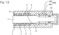
- Fig. 12 shows another example of a spindle device of a machine tool to which the bearing device is applied, the spindle device being of the built-in motor type.
- An electric motor 63A is provided between the bearing device J on the front side and the bearing 61 on the rear side within the housing 6.
- the electric motor 63A is a built-in motor formed from a stator 64 provided on the inner circumference of the housing 6 and a rotor 65 provided on the outer circumference of the spindle 7.
- a cooling structure for a bearing device according to the present invention can be effectively applied to any spindle device of the external motor type or the built-in motor type.
Landscapes
- Engineering & Computer Science (AREA)
- General Engineering & Computer Science (AREA)
- Mechanical Engineering (AREA)
- Rolling Contact Bearings (AREA)
- Mounting Of Bearings Or Others (AREA)
- Auxiliary Devices For Machine Tools (AREA)
- Machine Tool Sensing Apparatuses (AREA)
Abstract
Description
- This application claims priority to Japanese patent application No.
2016-219512, filed on November 10, 2016 - The present invention relates to a cooling structure for a bearing device and, for example, to a cooling structure for a spindle of a machine tool and a bearing incorporated into the spindle.
- For spindle devices of machine tools, it is necessary to suppress temperature rise in the devices to ensure processing accuracy. However, recent machine tools tend to be operated at higher speed in order to improve processing efficiency, resulting in increased heat generation from bearings that support the spindles as the speed increases. Moreover, spindle devices of so-called built-in motor type having a driving motor incorporated therein are becoming more common, which also causes heat generation in the devices.
- In view of speeding up and higher precision of the spindles, temperature rise in the bearings due to heat generation has to be minimized because it would lead to increase in preload. As means for suppressing temperature rise in a spindle device, compressed air for cooling is supplied to bearings to cool a spindle and the bearings (for example, Patent Document 1). In
Patent Document 1, cold air is injected into a space between two bearings at an angle relative to a rotational direction so as to produce a swirl flow, and the spindle and the bearings are cooled thereby. - Also, a cooling structure has been proposed, which is provided with an annular recess on a circumferential surface of an outer ring spacer, which faces an inner ring spacer, and with an air nozzle having an outlet open to the recess so as to discharge compressed air for cooling toward a circumferential surface of the inner ring spacer (Patent Document 2). The outer ring spacer is provided with a lubrication fluid discharge unit configured to supply air oil for lubrication for rolling bearings on both sides of the outer ring spacer.
- According to this configuration, the compressed air is discharged vigorously from a narrow nozzle hole into a space formed from the recess, and the compressed air is adiabatically expanded. This results in increase in the flow velocity and drop in the temperature of the compressed air. Thus, the rotary-side spacer is efficiently cooled.
-
- [Patent Document 1]
JP Laid-open Patent Publication No. 2000-161375 - [Patent Document 2]
JP Laid-open Patent Publication No. 2015-183738 - A bearing device including a cooling structure as described in
Patent Document 2 and three or more rows of rolling bearings was assembled to monitor temperatures at the respective rolling bearings. From the monitoring, it was found that the bearings arranged in multiple rows have different temperatures. The difference in temperatures varies depending on driving methods and/or bearing arrangement. For this reason, it is required to selectively cool a portion of the bearing device where a bearing temperature is high in order to effectively use limited compressed air. - Accordingly, the inventor made observation through testing or simulation on temperatures of respective bearings in a cooling structure for a bearing device to be implemented and considered adjusting flow rates from individual air nozzles to selectively cool a portion of the bearing device where a bearing temperature is high.
- However, depending on different operating conditions of the bearing device, different rolling bearings would have a high temperature. In particular, in machine tools, different rolling bearings would have a high temperature due to, for example, difference in load applied thereto depending on types of processing, even if the same machine tool is used. For this reason, there is a risk that suitable cooling may not be sufficiently performed, even if the flow rates from the individual air nozzles are regulated in accordance with the temperatures of the respective bearings determined from testing or simulation.
- The object of the present invention is to provide a cooling structure for a bearing device which is capable of, upon air-cooling rolling bearings arranged in three or more rows, selectively cooling a portion of the bearing device where a bearing temperature is high, even under varying operating conditions, so that limited compressed air can be effectively used.
- A cooling structure for a bearing device according to the present invention is a cooling structure for a bearing device, the bearing device having: rolling bearings arranged in three or more rows in an axial direction, each of the rolling bearings having an outer ring and an inner ring; outer ring spacers interposed between the outer rings of the respective rolling bearings adjacent in the rows; and inner ring spacers interposed between the inner rings of the respective rolling bearings adjacent in the rows, the outer rings and the outer ring spacers being disposed on an inner circumference of a housing, the inner rings and the inner ring spacers being fitted to an outer circumference of a rotation shaft,
the cooling structure including: - air nozzles provided in a plurality of the outer ring spacers and configured to discharge compressed air toward the inner ring spacers that face the outer ring spacers;
- valves configured to regulate the compressed air discharged from the respective air nozzles;
- a control unit configured to control the valves; and
- a plurality of temperature measuring units configured to measure temperatures of the rolling bearings in the three or more rows,
- wherein the control unit uses measurement values of the temperatures obtained by the plurality of temperature measuring units to control the valves so that the compressed air is discharged from the air nozzle selected in accordance with a predetermined rule.
- According to this configuration, the measurement values of the temperatures obtained by the temperature measuring units in the respective rolling bearings are used to control the valves so that the compressed air is discharged from a specified air nozzle. Thus, it is possible to selectively cool a portion of the bearing device where a bearing temperature is high, even under varying operating conditions, so that limited compressed air can be effectively used.
- It should be noted that the term "valve(s)" used herein generally refers to any means for performing open/close operation, switching operation, or flow rate regulation for the compressed air supplying passage.
- In the present invention, the control unit may be configured to use the measurement values of the temperatures obtained by the plurality of temperature measuring units to control the valves so that the compressed air is discharged from the air nozzle that faces the inner ring spacer adjacent to the rolling bearing having a highest temperature.
- In this configuration, while the compressed air is being discharged toward the inner ring spacer neighboring the rolling bearing having a highest temperature, if another rolling bearing has come to have a highest temperature during the operation, the compressed air will then be discharged toward the inner ring spacer neighboring that rolling bearing. In this way, the compressed air is always discharged toward the inner ring spacer neighboring the rolling bearing having a highest temperature, which enables simple control for effectively cooling each of the rolling bearings.
- In the present invention, the cooling structure may have a both-side exhaust passage between any of the outer ring spacers and the inner ring spacer which corresponds to said outer ring spacer, the both-side exhaust passage being configured to exhaust the compressed air discharged from the air nozzle toward the rolling bearings on both sides, which are adjacent to said outer ring spacer; and a one-side exhaust passage between any of the other outer ring spacers and the inner ring spacer which corresponds to said outer ring spacer, the one-side exhaust passage being configured to exhaust the compressed air discharged from the air nozzle toward the rolling bearing on one side, which is adjacent to said outer ring spacer.
- Each of the outer ring spacers may have a lubrication fluid discharge unit configured to supply lubrication fluid to the adjacent rolling bearing. Where the lubrication fluid and the compressed air discharged from the air nozzle toward the rolling bearings on both sides, which are adjacent to the outer ring spacer, flow in the same direction, the both-side exhaust passage for the compressed air allows the lubrication fluid to be assisted by the compressed air so that the lubrication fluid better passes through and flowing out from the rolling bearings, resulting in improved reliability of lubrication. In contrast, where the compressed air toward the rolling bearing on one side, which is adjacent to the outer ring spacer, flows oppositely to the lubrication fluid from another outer ring spacer toward the same rolling bearing, the lubrication fluid flows mixedly with the compressed air. Thus, the lubrication fluid has difficulty in passing through and flowing out from the rolling bearing, resulting in degradation in reliability of lubrication. In the latter case, provision of the one-side exhaust passage makes it possible to avoid mixing of the flows so as to ensure reliability of lubrication.
- In this configuration, the one-side exhaust passage may have a gap between the outer ring spacer and the inner ring spacer; and an annular space defined between the outer ring spacer and the inner ring spacer, the annular space having a larger radial dimension than that of the gap. The air nozzle may be open to the annular space. The annular space may have a portion on one side relative to the central axis of the air nozzle, the portion having a larger volume than that of a portion on the other side.
- The compressed air discharged from the air nozzle into the annular space is more likely to flow into a portion of the space which has a larger volume, of two portions of the annular space on both sides relative to the central axis of the air nozzle. Thus, the one-side exhaust passage can be configured to actively exhaust the compressed air discharged from the air nozzle toward the adjacent rolling bearing on one side.
- In the present invention, each of the outer ring spacers having the air nozzles may have a lubrication fluid discharge unit configured to supply lubrication fluid including air and lubrication oil to the adjacent rolling bearing.
- According to this configuration, the rolling bearings can be cooled and lubricated via means provided in the outer ring spacers. In such a case, it is also possible to selectively cool a portion of the bearing device where a bearing temperature is higher, even under varying operating conditions, in a similar manner as described above.
- It should be noted that when the one-side exhaust passage in this configuration is provided by changing the volumes of the two portions of the annular space on both sides relative to the central axis of the air nozzle, it is possible to prevent the compressed air discharged into the rolling bearing from flowing mixedly with the lubrication fluid discharged into the same rolling bearing from a different direction.
- Any combination of at least two configurations disclosed in the appended claims and/or the specification and/or the accompanying drawings should be construed as being included within the scope of the present invention. In particular, any combination of two or more of the appended claims should be equally construed as being included within the scope of the present invention.
- The present invention will be more clearly understood from the following description of preferred embodiments thereof, when taken in conjunction with the accompanying drawings. However, the embodiments and the drawings are given only for the purpose of illustration and explanation, and are not to be taken as limiting the scope of the present invention in any way whatsoever, which scope is to be determined by the appended claims. In the accompanying drawings, like reference numerals are used to denote like parts throughout the several views, and:
-
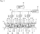
Fig. 1 illustrates a conceptual configuration of a cooling structure for a bearing device according to a first embodiment of the present invention; -
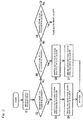
Fig. 2 is a flow chart showing an example of processing by a control unit of the cooling structure for the bearing device; -
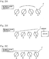
Fig. 3A illustrates an example of temperature gradient in the bearing device; -
Fig. 3B illustrates another example of temperature gradient in the bearing device; -
Fig. 3C illustrates still another example of temperature gradient in the bearing device; -
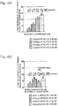
Fig. 4A shows an example of result of simulation showing a relation between locations of bearings and bearing temperatures in the cooling structure for the bearing device when compressed air is not supplied; -
Fig. 4B shows an example of result of simulation showing a relation between locations of bearings and bearing temperatures in the cooling structure for the bearing device when compressed air is supplied; -
Fig. 5 is a sectional view of a bearing device part in a spindle device of a machine tool having a cooling structure for a bearing device implemented according to the embodiment shown inFig. 1 ; -
Fig. 6 is a partial enlarged sectional view of the cooling structure for the rolling bearings in the middle two rows in the bearing device; -
Fig. 7 is a cross-sectional view of the spacer part of the bearing device; -
Fig. 8 is a partial enlarged sectional view of the cooling structure for the rolling bearing at an end of the bearing device; -
Fig. 9 is a partial section view of a cooling structure for a bearing device according to a second embodiment of the present invention; -
Fig. 10 is a partial enlarged sectional view of the cooling structure for the bearing device; -
Fig. 11 is a schematic sectional view showing an example of a spindle device of a machine tool to which a cooling structure for a bearing device according to each of the above-described embodiments is applied; and -
Fig. 12 is a schematic sectional view showing another example of a spindle device of a machine tool to which a cooling structure for a bearing device according to each of the above-described embodiments is applied. - A first embodiment of the present invention will be described with reference to
Fig. 1 to Fig. 8 . As shown inFig. 1 , a cooling structure for a bearing device J according to the first embodiment includes rollingbearings 1 arranged in three or more rows (four rows in the illustrated example) in an axial direction, each of the rollingbearings 1 having anouter ring 2 and aninner ring 3;outer ring spacers 4 interposed between theouter rings respective rolling bearings inner ring spacers 5 interposed between theinner rings outer rings 2 and theouter ring spacers 4 are disposed on an inner circumference of ahousing 6, and theinner rings 3 and theinner ring spacers 5 are fitted to an outer circumference of aspindle 7 that is a rotation shaft. - The cooling structure has
air nozzles 15 disposed in theouter ring spacers 4 and configured to discharge compressed air toward theinner ring spacers 5 that face theouter ring spacers 4;valves 51 configured to regulate the compressed air discharged from therespective air nozzles 15; acontrol unit 52 configured to control thevalves 51; and a plurality oftemperature measuring units bearings 1 in the three or more rows. - Each of the
air nozzles 15 is connected to anair supply device 57 configured to discharge the compressed air via a compressedair introduction passage 45 and a branchair supply passage 56. Each of thevalves 51 includes an electromagnetic valve, such as an electromagnetic on-off valve, and is operable to open and close in response to a control signal sent from thecontrol unit 52. Thevalves 51 may be collectively formed as a switching valve or a plurality of switching valves configured to switch flow passage(s). Thetemperature measuring units spindle 7 and thehousing 6 so as to respectively contact theinner ring 3 and theouter ring 2 in each of the rollingbearings 1. Thesetemperature measuring units control unit 52. Thetemperature measuring units 53 disposed on thespindle 7 may have a signal line (not illustrated) that is led out to a stationary side at an end of the spindle via a slip ring (not illustrated) or may use wireless communication, instead of a signal line. - The
control unit 52 uses measurement values of the temperatures of the rolling bearings 1 (for example, a difference between the inner ring temperature and the outer ring temperature) obtained by the plurality oftemperature measuring units valves 51 so as to discharge the compressed air from theair nozzle 15 selected in accordance with a predetermined rule. Thecontrol unit 52 includes an electronic circuit, such as a microcomputer, or a relay circuit. The predetermined rule may be arbitrarily designed. For example, the predetermined rule may include controlling thevalves 51 so that the compressed air is discharged from theair nozzle 15 that faces theinner ring spacer 5 adjacent to the rollingbearing 1 having a highest temperature.Fig. 2 shows a flow chart showing a specific example of such control, which will be described later. - The cooling structure may include a both-
side exhaust passage 58 between any of the outer ring spacers 4 (specifically, theouter ring spacer 4 in the middle row) and the correspondinginner ring spacer 5, the both-side exhaust passage being configured to exhaust the compressed air discharged from theair nozzle 15 toward the rollingbearings outer ring spacer 4. The cooling structure may include a one-side exhaust passage 59 between any of the other outer ring spacers (specifically, theouter ring spacer 4 on each of the opposite ends) and the correspondinginner ring spacer 5, the one-side exhaust passage being configured to exhaust the compressed air discharged from theair nozzle 15 toward the rollingbearing 1 on one side, which is adjacent to saidouter ring spacer 4. Each of theouter ring spacers 4 having theair nozzles 15 also has a lubricationfluid discharge unit 30 configured to supply lubrication fluid including air and lubrication oil to the adjacent rollingbearing 1. The both-side exhaust passage 58, the one-side exhaust passage 59, and the lubricationfluid discharge unit 30 will be specifically described later with reference toFig. 6 ,Fig. 8 and so on. - According to this configuration, the
control unit 52 uses measurement values of the temperatures obtained by thetemperature measuring units respective rolling bearings 1 to control thevalves 51 so as to discharge the compressed air from a specifiedair nozzle 15. Thus, it is possible to always selectively cool a portion of the bearing device where a bearing temperature is high, even under varying operating conditions, so that limited compressed air can be effectively used. - An example of processing by the
control unit 52 will be described with reference toFig. 2 . The temperatures of the inner ring and the outer ring of each rollingbearing 1 are measured by thetemperature measuring units 53, 54 (step S1) to determine which row of the rollingbearings 1 has a highest temperature (steps S2, S5, S8, etc.). To be more specific, first, it is determined whether or not a bearing temperature T in the N-th row (N is a natural number) is the highest temperature (step S2). In this example, the bearing temperature T is a difference between the temperature of the inner ring and the temperature of the outer ring. Although it is possible to determine the bearing temperature which affects the operation only with the temperature of the inner ring, use of such a difference allows accurate determination to be made. If the bearing temperature T in the N-th row is the highest temperature, thevalve 51 is switched to be open to theair nozzle 15 of the correspondingouter ring spacer 4 in the N-th row (step S3), and the compressed air is discharged from theair nozzle 15 of the correspondingouter ring spacer 4 in the N-th row (step S4). - If the condition that the bearing temperature T in the N-th row is the highest temperature is not satisfied in step S2, it is determined whether or not a bearing temperature T1 in the N+1-th row is the highest temperature (step S5). If it is the highest temperature, the
valve 51 is switched to be open to theair nozzle 15 of the correspondingouter ring spacer 4 in the N+1-th row (step S6), and the compressed air is discharged from theair nozzle 15 of the correspondingouter ring spacer 4 in the N+1-th row (step S7). - When neither of the bearing temperatures T, T1 in the N-th and N+1-th rows is not the highest temperature, it is determined whether or not a bearing temperature T2 in the N+2-th row is the highest temperature (step S8). Such determination is continued to be made until the condition that a bearing temperature in one of the rows is the highest temperature is satisfied. Once the condition is satisfied in a row, the valve is switched to discharge the compressed air to that row, and then the process returns to step 1. It should be noted that in a case where the determination is made to the N+n-th row that is an end of the rows, and the condition that a bearing temperature Tn is the highest temperature is not satisfied, the determination returns to and is continued from the first row that is the other end of the rows.
- In such a way, the compressed air is always discharged toward the
inner ring spacer 5 neighboring the rollingbearing 1 having a highest temperature, which enables simple control for effectively using the compressed air to cool each of the rollingbearings 1. - In addition, where the lubrication fluid and the compressed air discharged from the air nozzle toward the rolling bearings on both sides, which are adjacent to the outer ring spacer, flow in the same direction, the both-
side exhaust passage 58 for the compressed air allows the lubrication fluid to be assisted by the compressed air so that the lubrication fluid better passes through and flowing out from the rollingbearings 1, resulting in improved reliability of lubrication (see the middle outer ring spacer inFig. 1 ). In contrast, where the compressed air toward the rolling bearing on one side, which is adjacent to the outer ring spacer, flows oppositely to the lubrication fluid from another outer ring spacer toward the same rolling bearing, the lubrication fluid flows mixedly with the compressed air. Thus, the lubrication fluid has difficulty in passing through and flowing out from the rolling bearing, resulting in degradation in reliability of lubrication. In a case of the present embodiment, provision of the one-side exhaust passage 59 makes it possible to avoid mixing of the flows so as to ensure reliability of lubrication. -
Fig. 3A and Fig. 3B show different examples of temperature gradient generated among the rollingbearings 1 in the bearing device J having a configuration with four rows of bearings without cooling. The letters A to D in these figures denote the respective rows of the rollingbearings 1. In general, as shown inFig. 3A , the bearing temperatures tend to be relatively higher in the middle two rows B, C and relatively lower in the rows A, D at the opposite ends. Where themotor Fig. 11 ,Fig. 12 ) has a large influence, the bearing temperatures are relatively higher in the rows C, D on the side of themotor Fig. 3B . Application of the cooling structure for the bearing device according to the above embodiment allows the rows A to D to have similar bearing temperatures, as shown inFig. 3C . -
Fig. 4A shows an example of result of simulation showing a relation between locations of the bearings and bearing temperatures (temperature differences between the inner rings and the outer rings) in the bearing device J, in which a built-inmotor 63A is disposed at the rear end of the spindle, when compressed air is not supplied. As shown inFig. 4A , the bearing temperatures are higher in the rows C, D on the motor side when the compressed air is not supplied. Application of, for example, a cooling structure according to the embodiment shown inFig. 1 and supply of the compressed air between the C and D rows equalize the bearing temperatures in the rows A to D to some extent, as shown inFig. 4B . - Next, details of the cooling structure for the bearing device shown in
Fig. 1 will be described with reference toFig. 5 to Fig. 12 . - The cooling structure for a bearing device in this example is applied to a bearing device on the front side in a spindle device of a machine tool. It should be understood that application of the cooling structure is not limited to a spindle device of a machine tool.
- In
Fig. 5 , the front side of the spindle is illustrated on the left side in the figure, and the rear side is illustrated on the right side. As shown inFig. 5 , the bearing device J includes three or more (four in the illustrated example) rollingbearings 1 arranged in the axial direction, each of the rollingbearings 1 having anouter ring 2 and aninner ring 3;outer ring spacers 4 interposed between theouter rings adjacent rolling bearings inner ring spacers 5 interposed between theinner rings adjacent rolling bearings bearings 1 in the middle two rows are denoted with a subscript "I," and the rollingbearings 1 at the ends are denoted with a subscript "O"; however, they are simply referred to as "rollingbearings 1" when it is not necessary to distinguish them. Theouter rings 2 and theouter ring spacers 4 are disposed in thehousing 6, and theinner rings 3 and theinner ring spacers 5 are fitted to thespindle 7. Each of the rollingbearings 1 is an angular contact ball bearing and has a plurality of rollingelements 8 interposed between the raceway surfaces of theinner ring 3 and theouter ring 2. Therespective rolling elements 8 are retained at equal intervals in the circumferential direction by aretainer 9. The two rollingbearings bearings outer ring spacer 4 and theinner ring spacer 5 have a difference in width dimensions so that each of the rollingbearings 1 can be used with a set initial preload. - The
outer rings 2 and theouter ring spacers 4 are, for example, fitted with loose fit with respect to thehousing 6 and axially positioned by a steppedportion 6a of thehousing 6 and anend face cover 40. On the other hand, theinner rings 3 of the rollingbearings 1 and theinner ring spacers 5 are, for example, fitted with interference fit with respect to thespindle 7 and axially positioned by positioningspacers positioning spacer 42 on the left side ofFig. 5 is fixed by anut 43 screwed into thespindle 7. Each of the rollingbearings 1 is used by rotating the inner ring. - The cooling structure will be described.
-
Fig. 6 shows an enlarged view of a portion between the rollingbearings Fig. 5 . Theouter ring spacer 4 has an outerring spacer body 11 andflanges ring spacer body 11. Each of theflanges 12 forms a lubricationfluid discharge unit 30 which will be described later. The outerring spacer body 11 is formed so as to have a substantially T-shaped cross section, and theflanges ring spacer body 11. The outerring spacer body 11 has a larger inner diameter dimension than that of theflanges outer ring spacer 4 has an inner circumferential surface formed with arecess 13 defined by an inner circumferential surface of the outerring spacer body 11 and by side surfaces of theflanges recess 13 is an annular groove having a substantially rectangular cross section. Therecess 13 defines anannular space 14 between theouter ring 2 and theinner ring 3. The inner circumferential surface of theouter ring spacer 4 other than therecess 13, i.e., the inner circumferential surfaces of theflanges inner ring spacer 5 with a small radial gap δa. In this way, therecess 13 and the outer circumferential surface of theinner ring spacer 5 define therebetween theannular space 14 having a larger radial width than that of other portion. Theannular space 14 and the radial gap δa on both sides of theannular space 14 define the both-side exhaust passage 58. - The outer
ring spacer body 11 is provided with anair nozzle 15 configured to discharge compressed air A for cooling toward the outer circumferential surface of theinner ring spacer 5. Theair nozzle 15 has anoutlet 15a open to therecess 13 of the inner circumferential surface of theouter ring spacer 4. In this example, a plurality of (for example, three)air nozzles 15 are arranged at equal intervals in the circumferential direction (seeFig. 7 ). - As shown in
Fig. 7 , eachair nozzle 15 is inclined forwardly in a rotational direction of theinner ring spacer 5. That is, each air nozzle is located at a position offset from any radial straight line L on a cross section perpendicular to the axis of theouter ring spacer 4, in a direction orthogonal to the straight line L. Theair nozzle 15 is offset for the reason that the compressed air A thereby acts as a swirl flow in the rotation direction of theinner ring spacer 5 to improve the cooling effect. It should be noted that inFig. 5 andFig. 6 , each of theouter ring spacers 4 is shown as a cross section which passes the center line of theair nozzle 15. - The outer
ring spacer body 11 has an outer circumferential surface formed with anintroduction groove 16 for introducing the compressed air A into therespective air nozzles 15 from the outside of the bearing. Theintroduction groove 16 is provided in an intermediate part in the axial direction on the outer circumferential surface of theouter ring spacer 4 and is formed so as to have a shape of a circular arc that communicates with therespective air nozzles 15. Theintroduction groove 16 is formed on the outer circumferential surface of the outerring spacer body 11 over an angular range α that represents a major part in the circumferential direction, exclusive of a circumferential position where an air oil supply passage (not illustrated) that will be described later is provided. As shown inFig. 5 , thehousing 6 is provided with a compressedair introduction passage 45, and theintroduction groove 16 is formed so as to communicate with the compressedair introduction passage 45 via abranch passage 56. Thehousing 6 is externally provided with an air supply device 57 (Fig. 1 ) configured to supply the compressed air A to the compressedair introduction passage 45. -
Fig. 8 shows an enlarged view of the rollingbearing 1O at the end on the right side ofFig. 5 and the adjacent spacers. Description is omitted for the rollingbearing 1O at the end on the left side ofFig. 5 and the adjacent spacers because they have the same configurations as those shown inFig. 8 , except for being arranged in a laterally symmetrical manner. Similarly, the rollingbearings 1O and the adjacent spacers respectively have the same configurations as those of the rollingbearings - In
Fig. 8 , the rollingbearing 1O at the end has theouter ring spacer 4 provided with theflange 12 for the lubricationfluid supply unit 30 only on the side on which the rollingbearing 1O at the end, which is a main cooling target, is located. Theouter ring spacer 4 has a small diameter portion 2a on the inner circumferential surface on the opposite side from theflange 12, the small diameter portion 2a approaching the outer circumferential surface of theinner ring spacer 5 in a similar manner to that of theflange 12. Anannular recess 13A is defined by a side surface of the small diameter portion 2a, a side surface of theflange 12 and a middle portion of the inner circumferential surface of theouter ring spacer 4 in the widthwise direction. Therecess 13A defines anannular space 14A between the inner circumferential surface of theouter ring spacer 4 and the outer circumferential surface of theinner ring spacer 5. The small diameter portion 2a has a side surface on theannular space 14A side, which is an inclined surface whose inner diameter side approaches the end in the spacer width direction. Theannular space 14A and the radial gap δa on one side of theannular space 14A define the one-side exhaust passage 59. - The
annular space 14A is defined in an asymmetrical shape in the axial direction such that theannular space 14A has a portion 14A1 on the side of the rollingbearing 1O at the end, which is a main cooling target, relative to the central axis O15 of theair nozzle 15, the portion 14A1 having a larger volume than that of a portion 14A2 on the side of themiddle rolling bearing 1I. In particular, the portion 14A1 of theannular space 14A has a longer axial length than that of the portion 14A2. A volume ratio of the portions 14A1, 14A2 of theannular space 14A may be suitably selected, such as 6:4, 7:3. The portion 14A2 that is smaller may be in a range from an opening edge of theair nozzle 15 to the central axis O15, but may preferably be in a range from the central axis O15 to a position at one fifth the width of the outer ring spacer in the direction toward the rollingbearing 1I side, more preferably in a range from the central axis O15 to a position at one tenth the width of the outer ring spacer in the direction toward the rollingbearing 1I side. - A lubrication structure will be described.
- As shown in
Fig. 5 , each of theouter ring spacers 4 has the flange(s) 12 (Fig. 6 ,Fig. 8 ) as a means for forming the lubricationfluid discharge unit 30. Each of theflanges 12 protrudes into the bearing and faces the outer circumferential surface of theinner ring 3 with an annular gap δb for air oil passage therebetween. Each of theflanges 12 is disposed so as to enter the bearing, covering the outer circumferential surface of theinner ring 3. Each of theflanges 12 has a tip end portion disposed radially inside with respect to the inner circumferential surface of theretainer 9. - Each of the two
flanges 12 provided to theouter ring spacer 4 shown inFig. 6 or theflange 12 provided to theouter ring spacer 4 shown inFig. 8 , in either case, has alubrication nozzle 31 open to the annular gap δb between theflange 12 and the outer circumferential surface of theinner ring 3 to supply lubrication fluid, such as air oil. Thelubrication nozzle 31 is inclined so as to approach the inner diameter side toward the bearing side and has an outlet open to a portion of the inner circumferential surface of theflange 12, which faces to theinner ring 3. Thelubrication nozzle 31 is supplied with the air oil through a lubrication fluid supply passage (not illustrated) provided in thehousing 6 and the outerring spacer body 11. Theinner ring 3 is provided with anannular recess 3a at a position at which the extension line of thelubrication nozzle 31 intersects the outer circumferential surface of theinner ring 3. - Oil of the air oil discharged from the
lubrication nozzle 31 of theflange 12 accumulates in theannular recess 3a, and the oil is guided toward the bearing center side along the outer circumferential surface of theinner ring 3, which is an inclined surface, due to a centrifugal force associated with rotation of theinner ring 3. - An exhaust structure will be described.
- As shown in
Fig. 5 , the bearing device J is provided with anexhaust passage 46 configured to exhaust the compressed air for cooling and air oil that is lubrication fluid for lubrication. Theexhaust passage 46 includes anexhaust groove 47 provided in a portion of the outerring spacer body 11 in the circumferential direction, and aradial exhaust hole 48 and anaxial exhaust hole 49 that are provided in thehousing 6 and communicate with theexhaust groove 47. Theexhaust groove 47 in the outerring spacer body 11 is defined over a circumferential position diagonal to a position at which the lubricant oil supply passage is provided. - The effect of the cooling structure for the bearing device having the above configuration will be described.
- The cooling structure for the bearing device is formed from four rows of rolling
bearings 2, as shown inFig. 5 . The compressed air is dividedly discharged from oneair nozzle 15 for the two rollingbearings air nozzles bearings bearings 1 in accordance with the locations of the rollingbearings 1. It is also possible to effectively cool theindividual rolling bearings 1 in the following manner. - Each of the
outer ring spacers 4 shown inFig. 6 andFig. 8 has theair nozzle 15 that allows the compressed air A for cooling to be blown toward the outer circumferential surface of theinner ring spacer 5. Here, the compressed air A is discharged from thenarrow air nozzle 15 into the largeannular space air nozzle 15 has a volume VI and a temperature T1, and the compressed air in theannular space annular space inner ring spacer 5 can be efficiently cooled by blowing the compressed air A having a low temperature at a high speed onto theinner ring spacer 5. - As the
air nozzle 15 is inclined forwardly in the rotational direction of theinner ring spacer 5, the compressed air A discharged from theair nozzle 15 flows in the axial direction while swirling along the outer circumferential surface of theinner ring spacer 5 and is exhausted to the outside of the bearing via theexhaust passage 46. As the compressed air A swirls, the compressed air A contacts the outer circumferential surface of theinner ring spacer 5 for a longer time, when compared with the case where the compressed air flows straightly in the axial direction. Thus, theinner ring spacer 5 can be more efficiently cooled. - In this way, by efficiently cooling the
inner ring spacer 5, theinner ring 3 of the rollingbearing 1 and thespindle 7 can be effectively cooled via theinner ring spacer 5. The cooling efficiency of this cooling structure can be improved merely by contriving the structure in such a way that theouter ring spacer 4 has the inner circumferential surface provided with anannular recess air nozzle 15 is inclined. Therefore, the air supply device for supplying the compressed air A does not have to have a large output, and power consumption can be suppressed. - In addition, provision of the
recess outer ring spacer 4 provides the following effect. That is, the compressed air A discharged into theannular space recess inner ring spacer 5 is exhausted to the outside of the bearing via the radial gap δa between theouter ring spacer 4 and theinner ring spacer 5. In this process, at least a part of the compressed air A flows into the bearing. As the radial gap δa is narrower than theannular space elements 8 during rotation can be suppressed. - Next, an explanation will be given with respect to selectively supplying the compressed air to the rolling
bearing 1 on one side as well as preventing flow mixing between the flows of the lubrication fluid and the compressed air in the rollingbearing 1 on the opposite side. InFig. 1 , the flow of the compressed air is shown with arrows of the same thickness as that of visible outlines, and the flow of the lubrication fluid is shown with wide line arrows. The compressed air discharged from theair nozzle 15 of theouter ring spacer 4 that is adjacent to the rollingbearing 1O at the end passes through the gap between theouter ring spacer 4 and theinner ring spacer 5, enters the next rolling bearing 1I on the side of the middle section, and then is mixed with the flow of the lubrication fluid. - However, in this embodiment, the
annular space 14A of theouter ring spacer 4 adjacent to the rollingbearing 1O at the end is defined in an asymmetrical shape in the axial direction such that theannular space 14A has a portion 14A1 on the side of the rollingbearing 1O at the end relative to the central axis O15 of theair nozzle 15, the portion 14A1 having a larger volume than that of a portion 14A2 on the side of themiddle rolling bearing 1I, as described above. - That is, in the
annular space 14A, the portion 14A1 on the supply side of lubrication fluid (the side on which the lubrication fluid discharge unit is provided) relative to the central axis O15 of theair nozzle 15 has a larger volume than that of the portion 14A2 on the non-supply side (the side on which the lubrication fluid discharge unit is not provided). The compressed air discharged into theannular space 14A is more likely to flow toward the side of the space portion 14A1 that has a larger volume, i.e., toward the rollingbearing 1O at the end which is the supply side of the lubrication fluid. Thus, the rollingbearing 1O can be effectively cooled. In addition, as less compressed air flows toward the rollingbearing 1I on the opposite side, mixing of the flows of the compressed air and of the lubrication fluid supplied from otherouter ring spacer 4 is reduced in the rollingbearing 1I on the opposite side. -
Fig. 9 andFig. 10 show a second embodiment of the present invention. This embodiment has the same configuration as that of the first embodiment described with reference toFig. 1 to Fig. 8 , unless otherwise specifically described. In the second embodiment, anannular space 14B defined between theouter ring spacer 4 and theinner ring spacer 5 that are adjacent to the rollingbearing 1o at the end is defined by therecess 13a formed on the inner circumferential surface of theouter ring spacer 4 and by the recess 13b formed on the outer circumferential surface of theinner ring spacer 5. - As in the example shown in
Fig. 8 , where theannular space 14A is defined only by therecess 13A that is formed on the inner circumferential surface of theouter ring spacer 4, theinner ring spacer 5 may have a simple shape without unevenness, which is easy to produce. However, due to the limitation in the radial dimension of theouter ring spacer 4, it may be difficult to have theannular space 14A with a sufficient volume. In contrast, as in the second embodiment shown inFig. 9 andFig. 10 , where theannular space 14B is defined by therecess 13a formed on theouter ring spacer 4 and the recess 13b formed on theinner ring spacer 5, it is possible to obtain theannular space 14B with a large volume so as to allow the compressed air discharged from theair nozzle 15 to adiabatically expand sufficiently, and thereby enhance the cooling effect. -
Fig. 11 shows a sectional view showing an overview of a spindle device of a machine tool to which each of the embodiments described above is applied. Thespindle 7 has a front portion supported by a bearing device J according to any one of the above embodiments and a rear portion supported by another rollingbearing 61. Thehousing 6 has an outer circumference provided with aliquid cooling device 62 of an outer cylinder cooling type. Thespindle 7 has a rear end coupled to anelectric motor 63 outside thehousing 6. -
Fig. 12 shows another example of a spindle device of a machine tool to which the bearing device is applied, the spindle device being of the built-in motor type. Anelectric motor 63A is provided between the bearing device J on the front side and the bearing 61 on the rear side within thehousing 6. Theelectric motor 63A is a built-in motor formed from astator 64 provided on the inner circumference of thehousing 6 and arotor 65 provided on the outer circumference of thespindle 7. - As shown in the respective examples in
Fig. 11 andFig. 12 , a cooling structure for a bearing device according to the present invention can be effectively applied to any spindle device of the external motor type or the built-in motor type. - Although the preferred embodiments of the present invention have been described above with reference to the accompanying drawings, those skilled in the art would easily conceive of various changes and modifications within the obvious range in view of the specification. Accordingly, such changes and modifications are to be construed as included in the scope of the present invention defined by the appended claims.
-
- 1, 1O, 1I...
- rolling bearing
- 2...
- outer ring
- 3...
- inner ring
- 4...
- outer ring spacer
- 5...
- inner ring spacer
- 6...
- housing
- 7...
- spindle
- 8...
- rolling element
- 11...
- outer ring spacer body
- 12...
- flange
- 13, 13A, 13a, 13b...
- recess
- 14, 14A, 14B...
- annular space
- 14A1, 14A2......
- portion of the annular space
- 15...
- air nozzle
- 30...
- lubrication fluid discharge unit
- 31...
- lubrication nozzle
- 45...
- compressed air introduction passage
- 46...
- exhaust passage
- 51...
- valve
- 52...
- control unit
- 56...
- branch air supply passage
- 57...
- air supply device
- 58...
- both-side exhaust passage
- 59...
- one-side exhaust passage
- A...
- compressed air
- O15...
- central axis
Claims (5)
- A cooling structure for a bearing device, the bearing device having: rolling bearings arranged in three or more rows in an axial direction, each of the rolling bearings having an outer ring and an inner ring; outer ring spacers interposed between the outer rings of the respective rolling bearings adjacent in the rows; and inner ring spacers interposed between the inner rings of the respective rolling bearings adjacent in the rows, the outer rings and the outer ring spacers being disposed on an inner circumference of a housing, the inner rings and the inner ring spacers being fitted to an outer circumference of a rotation shaft,
the cooling structure comprising:air nozzles provided in a plurality of the outer ring spacers and configured to discharge compressed air toward the inner ring spacers that face the outer ring spacers;valves configured to regulate the compressed air discharged from the respective air nozzles;a control unit configured to control the valves; anda plurality of temperature measuring units configured to measure temperatures of the rolling bearings in the three or more rows,wherein the control unit uses measurement values of the temperatures obtained by the plurality of temperature measuring units to control the valves so that the compressed air is discharged from the air nozzle selected in accordance with a predetermined rule. - The cooling structure for a bearing device as claimed in claim 1, wherein the control unit is configured to use the measurement values of the temperatures obtained by the plurality of temperature measuring units to control the valves so that the compressed air is discharged from the air nozzle that faces the inner ring spacer adjacent to the rolling bearing having a highest temperature.
- The cooling structure for a bearing device as claimed in claim 1 or 2, wherein the cooling structure comprises:a both-side exhaust passage between any of the outer ring spacers and the inner ring spacer which corresponds to said outer ring spacer, the both-side exhaust passage being configured to exhaust the compressed air discharged from the air nozzle toward the rolling bearings on both sides, which are adjacent to said outer ring spacer; anda one-side exhaust passage between any of the other outer ring spacers and the inner ring spacer which corresponds to said outer ring spacer, the one-side exhaust passage being configured to exhaust the compressed air discharged from the air nozzle toward the rolling bearing on one side, which is adjacent to said outer ring spacer.
- The cooling structure for a bearing device as claimed in claim 3, wherein the one-side exhaust passage has a gap between the outer ring spacer and the inner ring spacer; and an annular space defined between the outer ring spacer and the inner ring spacer, the annular space having a larger radial dimension than that of the gap,
the air nozzle is open to the annular space, and
the annular space has a portion on one side relative to a central axis of the air nozzle, the portion having a larger volume than that of a portion on the other side. - The cooling structure for a bearing device as claimed in any one of claims 1 to 4, wherein each of the outer ring spacers having the air nozzles has a lubrication fluid discharge unit configured to supply lubrication fluid including air and lubrication oil to the adjacent rolling bearing.
Applications Claiming Priority (2)
| Application Number | Priority Date | Filing Date | Title |
|---|---|---|---|
| JP2016219512A JP6831162B2 (en) | 2016-11-10 | 2016-11-10 | Bearing device cooling structure |
| PCT/JP2017/040200 WO2018088414A1 (en) | 2016-11-10 | 2017-11-08 | Cooling structure of bearing device |
Publications (3)
| Publication Number | Publication Date |
|---|---|
| EP3540255A1 true EP3540255A1 (en) | 2019-09-18 |
| EP3540255A4 EP3540255A4 (en) | 2020-07-08 |
| EP3540255B1 EP3540255B1 (en) | 2021-09-15 |
Family
ID=62109578
Family Applications (1)
| Application Number | Title | Priority Date | Filing Date |
|---|---|---|---|
| EP17868539.2A Active EP3540255B1 (en) | 2016-11-10 | 2017-11-08 | Cooling structure for a bearing device |
Country Status (5)
| Country | Link |
|---|---|
| EP (1) | EP3540255B1 (en) |
| JP (1) | JP6831162B2 (en) |
| KR (1) | KR102465342B1 (en) |
| CN (1) | CN110036215B (en) |
| WO (1) | WO2018088414A1 (en) |
Cited By (1)
| Publication number | Priority date | Publication date | Assignee | Title |
|---|---|---|---|---|
| CN112943808A (en) * | 2021-03-23 | 2021-06-11 | 北新集团建材股份有限公司 | Bearing automatic lubrication system and breaker thereof |
Families Citing this family (7)
| Publication number | Priority date | Publication date | Assignee | Title |
|---|---|---|---|---|
| JP6967495B2 (en) * | 2018-09-03 | 2021-11-17 | Ntn株式会社 | Bearing equipment |
| JP7206141B2 (en) * | 2019-03-25 | 2023-01-17 | Ntn株式会社 | bearing device |
| CN113070195B (en) * | 2021-04-01 | 2022-07-15 | 山东金帝精密机械科技股份有限公司 | Plastic-impregnated cooling device of bearing retainer |
| CN113294431B (en) * | 2021-04-27 | 2022-08-30 | 洛阳轴承研究所有限公司 | Thrust bearing group of series connection matched stack |
| JP7779083B2 (en) * | 2021-10-28 | 2025-12-03 | 株式会社ジェイテクト | Spindle device |
| KR102663414B1 (en) | 2022-03-23 | 2024-05-08 | 에스케이온 주식회사 | Rolling apparatus for secondary battery electrode sheet, anode electrode manufactured thereby and secondary battery |
| CN119802078A (en) * | 2024-12-30 | 2025-04-11 | 宁波市镇海金金耐驰轴承有限公司 | A processing method for rolling bearing |
Family Cites Families (15)
| Publication number | Priority date | Publication date | Assignee | Title |
|---|---|---|---|---|
| JPH1034494A (en) * | 1996-07-22 | 1998-02-10 | Okuma Mach Works Ltd | Bearing device |
| JP2000161375A (en) | 1998-11-26 | 2000-06-13 | Matsuura Machinery Corp | Rotary main spindle cooling structure |
| JP2004100729A (en) * | 2002-09-05 | 2004-04-02 | Mitsubishi Heavy Ind Ltd | Sliding bearing |
| EP1579951B1 (en) * | 2004-03-22 | 2008-03-19 | Paul Müller GmbH & Co. KG Unternehmensbeteiligungen | Machine tool spindle with a bearing provided with a capilar duct for conducting lubricant |
| JP4569747B2 (en) * | 2004-07-07 | 2010-10-27 | 株式会社ジェイテクト | Lubricant supply device for bearings |
| JP2006118526A (en) * | 2004-10-19 | 2006-05-11 | Ntn Corp | Lubrication device of rolling bearing |
| JP2006194402A (en) * | 2005-01-17 | 2006-07-27 | Jtekt Corp | Rolling bearing device |
| JP5607285B2 (en) * | 2006-06-23 | 2014-10-15 | 日本精工株式会社 | Bearing device |
| JP2008106891A (en) * | 2006-10-27 | 2008-05-08 | Ntn Corp | Pre-load adjustment method of rolling bearing and its device |
| JP5419392B2 (en) * | 2007-08-24 | 2014-02-19 | Ntn株式会社 | Rolling bearing device |
| JP2008075882A (en) * | 2007-12-11 | 2008-04-03 | Nsk Ltd | Bearing device |
| EP2910806B1 (en) * | 2012-09-24 | 2021-05-19 | NTN Corporation | Bearing device with a cooling structure |
| JP2015117820A (en) * | 2013-11-18 | 2015-06-25 | Ntn株式会社 | Cooling structure of bearing device |
| WO2015146569A1 (en) * | 2014-03-22 | 2015-10-01 | Ntn株式会社 | Cooling structure for bearing device |
| JP6385089B2 (en) | 2014-03-22 | 2018-09-05 | Ntn株式会社 | Cooling structure of bearing device |
-
2016
- 2016-11-10 JP JP2016219512A patent/JP6831162B2/en active Active
-
2017
- 2017-11-08 KR KR1020197015962A patent/KR102465342B1/en active Active
- 2017-11-08 CN CN201780069284.1A patent/CN110036215B/en active Active
- 2017-11-08 WO PCT/JP2017/040200 patent/WO2018088414A1/en not_active Ceased
- 2017-11-08 EP EP17868539.2A patent/EP3540255B1/en active Active
Cited By (2)
| Publication number | Priority date | Publication date | Assignee | Title |
|---|---|---|---|---|
| CN112943808A (en) * | 2021-03-23 | 2021-06-11 | 北新集团建材股份有限公司 | Bearing automatic lubrication system and breaker thereof |
| CN112943808B (en) * | 2021-03-23 | 2022-07-05 | 北新集团建材股份有限公司 | Bearing automatic lubrication system and breaker thereof |
Also Published As
| Publication number | Publication date |
|---|---|
| JP2018076923A (en) | 2018-05-17 |
| WO2018088414A8 (en) | 2019-05-31 |
| CN110036215A (en) | 2019-07-19 |
| CN110036215B (en) | 2021-03-09 |
| KR20190076027A (en) | 2019-07-01 |
| EP3540255B1 (en) | 2021-09-15 |
| EP3540255A4 (en) | 2020-07-08 |
| KR102465342B1 (en) | 2022-11-08 |
| WO2018088414A1 (en) | 2018-05-17 |
| JP6831162B2 (en) | 2021-02-17 |
Similar Documents
| Publication | Publication Date | Title |
|---|---|---|
| EP3540255B1 (en) | Cooling structure for a bearing device | |
| EP3124812B1 (en) | Cooling structure for bearing device | |
| US8956050B2 (en) | Rolling bearing and rolling bearing assembly | |
| EP2910806B1 (en) | Bearing device with a cooling structure | |
| US20140232218A1 (en) | Cooling system and cooling method for cooling rotating electrical machine | |
| US10072710B2 (en) | Cooling structure for bearing device | |
| EP2738424B1 (en) | Ball screw bearing device | |
| US10001170B2 (en) | Rolling bearing | |
| EP3851692B1 (en) | Bearing device cooling structure, and main spindle device of machine tool | |
| KR102448407B1 (en) | Cooling structure of bearing device | |
| JP6385090B2 (en) | Cooling structure of bearing device | |
| JP2014062620A (en) | Cooling structure for bearing device | |
| JP6385089B2 (en) | Cooling structure of bearing device | |
| JP6609003B2 (en) | Cooling structure of bearing device | |
| JP2018066384A (en) | Cooling structure of bearing device | |
| JP2008240946A (en) | Lubricating device for rolling bearing | |
| JP2006266112A (en) | Turbine moving blade | |
| WO2019073911A1 (en) | Cooling structure for bearing device | |
| WO2018181032A1 (en) | Cooling structure for bearing device | |
| WO2016208505A1 (en) | Cooling liquid discharge device, ball screw apparatus | |
| JP2008157403A (en) | Bearing cooling device | |
| JP2017031984A (en) | Rolling bearing | |
| JP2020041647A (en) | Structure for cooling bearing device |
Legal Events
| Date | Code | Title | Description |
|---|---|---|---|
| STAA | Information on the status of an ep patent application or granted ep patent |
Free format text: STATUS: THE INTERNATIONAL PUBLICATION HAS BEEN MADE |
|
| PUAI | Public reference made under article 153(3) epc to a published international application that has entered the european phase |
Free format text: ORIGINAL CODE: 0009012 |
|
| STAA | Information on the status of an ep patent application or granted ep patent |
Free format text: STATUS: REQUEST FOR EXAMINATION WAS MADE |
|
| 17P | Request for examination filed |
Effective date: 20190605 |
|
| AK | Designated contracting states |
Kind code of ref document: A1 Designated state(s): AL AT BE BG CH CY CZ DE DK EE ES FI FR GB GR HR HU IE IS IT LI LT LU LV MC MK MT NL NO PL PT RO RS SE SI SK SM TR |
|
| AX | Request for extension of the european patent |
Extension state: BA ME |
|
| DAV | Request for validation of the european patent (deleted) | ||
| DAX | Request for extension of the european patent (deleted) | ||
| A4 | Supplementary search report drawn up and despatched |
Effective date: 20200609 |
|
| RIC1 | Information provided on ipc code assigned before grant |
Ipc: B23Q 11/12 20060101ALI20200604BHEP Ipc: F16C 35/12 20060101ALI20200604BHEP Ipc: F16C 33/66 20060101ALI20200604BHEP Ipc: F16C 41/00 20060101ALI20200604BHEP Ipc: F16C 19/52 20060101ALI20200604BHEP Ipc: F16C 19/54 20060101ALI20200604BHEP Ipc: F16C 19/18 20060101ALI20200604BHEP Ipc: F16C 37/00 20060101AFI20200604BHEP |
|
| REG | Reference to a national code |
Ref country code: DE Ref legal event code: R079 Ref document number: 602017046220 Country of ref document: DE Free format text: PREVIOUS MAIN CLASS: F16C0037000000 Ipc: B23Q0017090000 |
|
| RIC1 | Information provided on ipc code assigned before grant |
Ipc: B23Q 11/12 20060101ALI20210506BHEP Ipc: F16C 35/12 20060101ALI20210506BHEP Ipc: F16C 19/54 20060101ALI20210506BHEP Ipc: F16C 41/00 20060101ALI20210506BHEP Ipc: F16C 19/18 20060101ALI20210506BHEP Ipc: F16C 19/52 20060101ALI20210506BHEP Ipc: F16C 33/66 20060101ALI20210506BHEP Ipc: F16C 37/00 20060101ALI20210506BHEP Ipc: B23Q 17/09 20060101AFI20210506BHEP |
|
| GRAP | Despatch of communication of intention to grant a patent |
Free format text: ORIGINAL CODE: EPIDOSNIGR1 |
|
| STAA | Information on the status of an ep patent application or granted ep patent |
Free format text: STATUS: GRANT OF PATENT IS INTENDED |
|
| INTG | Intention to grant announced |
Effective date: 20210614 |
|
| GRAS | Grant fee paid |
Free format text: ORIGINAL CODE: EPIDOSNIGR3 |
|
| GRAA | (expected) grant |
Free format text: ORIGINAL CODE: 0009210 |
|
| STAA | Information on the status of an ep patent application or granted ep patent |
Free format text: STATUS: THE PATENT HAS BEEN GRANTED |
|
| AK | Designated contracting states |
Kind code of ref document: B1 Designated state(s): AL AT BE BG CH CY CZ DE DK EE ES FI FR GB GR HR HU IE IS IT LI LT LU LV MC MK MT NL NO PL PT RO RS SE SI SK SM TR |
|
| REG | Reference to a national code |
Ref country code: CH Ref legal event code: EP |
|
| REG | Reference to a national code |
Ref country code: DE Ref legal event code: R096 Ref document number: 602017046220 Country of ref document: DE |
|
| REG | Reference to a national code |
Ref country code: IE Ref legal event code: FG4D |
|
| REG | Reference to a national code |
Ref country code: AT Ref legal event code: REF Ref document number: 1430159 Country of ref document: AT Kind code of ref document: T Effective date: 20211015 |
|
| REG | Reference to a national code |
Ref country code: LT Ref legal event code: MG9D |
|
| REG | Reference to a national code |
Ref country code: NL Ref legal event code: MP Effective date: 20210915 |
|
| PG25 | Lapsed in a contracting state [announced via postgrant information from national office to epo] |
Ref country code: RS Free format text: LAPSE BECAUSE OF FAILURE TO SUBMIT A TRANSLATION OF THE DESCRIPTION OR TO PAY THE FEE WITHIN THE PRESCRIBED TIME-LIMIT Effective date: 20210915 Ref country code: SE Free format text: LAPSE BECAUSE OF FAILURE TO SUBMIT A TRANSLATION OF THE DESCRIPTION OR TO PAY THE FEE WITHIN THE PRESCRIBED TIME-LIMIT Effective date: 20210915 Ref country code: HR Free format text: LAPSE BECAUSE OF FAILURE TO SUBMIT A TRANSLATION OF THE DESCRIPTION OR TO PAY THE FEE WITHIN THE PRESCRIBED TIME-LIMIT Effective date: 20210915 Ref country code: FI Free format text: LAPSE BECAUSE OF FAILURE TO SUBMIT A TRANSLATION OF THE DESCRIPTION OR TO PAY THE FEE WITHIN THE PRESCRIBED TIME-LIMIT Effective date: 20210915 Ref country code: NO Free format text: LAPSE BECAUSE OF FAILURE TO SUBMIT A TRANSLATION OF THE DESCRIPTION OR TO PAY THE FEE WITHIN THE PRESCRIBED TIME-LIMIT Effective date: 20211215 Ref country code: LT Free format text: LAPSE BECAUSE OF FAILURE TO SUBMIT A TRANSLATION OF THE DESCRIPTION OR TO PAY THE FEE WITHIN THE PRESCRIBED TIME-LIMIT Effective date: 20210915 Ref country code: BG Free format text: LAPSE BECAUSE OF FAILURE TO SUBMIT A TRANSLATION OF THE DESCRIPTION OR TO PAY THE FEE WITHIN THE PRESCRIBED TIME-LIMIT Effective date: 20211215 |
|
| REG | Reference to a national code |
Ref country code: AT Ref legal event code: MK05 Ref document number: 1430159 Country of ref document: AT Kind code of ref document: T Effective date: 20210915 |
|
| PG25 | Lapsed in a contracting state [announced via postgrant information from national office to epo] |
Ref country code: LV Free format text: LAPSE BECAUSE OF FAILURE TO SUBMIT A TRANSLATION OF THE DESCRIPTION OR TO PAY THE FEE WITHIN THE PRESCRIBED TIME-LIMIT Effective date: 20210915 Ref country code: GR Free format text: LAPSE BECAUSE OF FAILURE TO SUBMIT A TRANSLATION OF THE DESCRIPTION OR TO PAY THE FEE WITHIN THE PRESCRIBED TIME-LIMIT Effective date: 20211216 |
|
| PG25 | Lapsed in a contracting state [announced via postgrant information from national office to epo] |
Ref country code: AT Free format text: LAPSE BECAUSE OF FAILURE TO SUBMIT A TRANSLATION OF THE DESCRIPTION OR TO PAY THE FEE WITHIN THE PRESCRIBED TIME-LIMIT Effective date: 20210915 |
|
| PG25 | Lapsed in a contracting state [announced via postgrant information from national office to epo] |
Ref country code: IS Free format text: LAPSE BECAUSE OF FAILURE TO SUBMIT A TRANSLATION OF THE DESCRIPTION OR TO PAY THE FEE WITHIN THE PRESCRIBED TIME-LIMIT Effective date: 20220115 Ref country code: SM Free format text: LAPSE BECAUSE OF FAILURE TO SUBMIT A TRANSLATION OF THE DESCRIPTION OR TO PAY THE FEE WITHIN THE PRESCRIBED TIME-LIMIT Effective date: 20210915 Ref country code: SK Free format text: LAPSE BECAUSE OF FAILURE TO SUBMIT A TRANSLATION OF THE DESCRIPTION OR TO PAY THE FEE WITHIN THE PRESCRIBED TIME-LIMIT Effective date: 20210915 Ref country code: RO Free format text: LAPSE BECAUSE OF FAILURE TO SUBMIT A TRANSLATION OF THE DESCRIPTION OR TO PAY THE FEE WITHIN THE PRESCRIBED TIME-LIMIT Effective date: 20210915 Ref country code: PT Free format text: LAPSE BECAUSE OF FAILURE TO SUBMIT A TRANSLATION OF THE DESCRIPTION OR TO PAY THE FEE WITHIN THE PRESCRIBED TIME-LIMIT Effective date: 20220117 Ref country code: PL Free format text: LAPSE BECAUSE OF FAILURE TO SUBMIT A TRANSLATION OF THE DESCRIPTION OR TO PAY THE FEE WITHIN THE PRESCRIBED TIME-LIMIT Effective date: 20210915 Ref country code: NL Free format text: LAPSE BECAUSE OF FAILURE TO SUBMIT A TRANSLATION OF THE DESCRIPTION OR TO PAY THE FEE WITHIN THE PRESCRIBED TIME-LIMIT Effective date: 20210915 Ref country code: ES Free format text: LAPSE BECAUSE OF FAILURE TO SUBMIT A TRANSLATION OF THE DESCRIPTION OR TO PAY THE FEE WITHIN THE PRESCRIBED TIME-LIMIT Effective date: 20210915 Ref country code: EE Free format text: LAPSE BECAUSE OF FAILURE TO SUBMIT A TRANSLATION OF THE DESCRIPTION OR TO PAY THE FEE WITHIN THE PRESCRIBED TIME-LIMIT Effective date: 20210915 Ref country code: CZ Free format text: LAPSE BECAUSE OF FAILURE TO SUBMIT A TRANSLATION OF THE DESCRIPTION OR TO PAY THE FEE WITHIN THE PRESCRIBED TIME-LIMIT Effective date: 20210915 Ref country code: AL Free format text: LAPSE BECAUSE OF FAILURE TO SUBMIT A TRANSLATION OF THE DESCRIPTION OR TO PAY THE FEE WITHIN THE PRESCRIBED TIME-LIMIT Effective date: 20210915 |
|
| REG | Reference to a national code |
Ref country code: DE Ref legal event code: R097 Ref document number: 602017046220 Country of ref document: DE |
|
| PG25 | Lapsed in a contracting state [announced via postgrant information from national office to epo] |
Ref country code: MC Free format text: LAPSE BECAUSE OF FAILURE TO SUBMIT A TRANSLATION OF THE DESCRIPTION OR TO PAY THE FEE WITHIN THE PRESCRIBED TIME-LIMIT Effective date: 20210915 |
|
| REG | Reference to a national code |
Ref country code: CH Ref legal event code: PL |
|
| PLBE | No opposition filed within time limit |
Free format text: ORIGINAL CODE: 0009261 |
|
| STAA | Information on the status of an ep patent application or granted ep patent |
Free format text: STATUS: NO OPPOSITION FILED WITHIN TIME LIMIT |
|
| PG25 | Lapsed in a contracting state [announced via postgrant information from national office to epo] |
Ref country code: LU Free format text: LAPSE BECAUSE OF NON-PAYMENT OF DUE FEES Effective date: 20211108 Ref country code: DK Free format text: LAPSE BECAUSE OF FAILURE TO SUBMIT A TRANSLATION OF THE DESCRIPTION OR TO PAY THE FEE WITHIN THE PRESCRIBED TIME-LIMIT Effective date: 20210915 Ref country code: BE Free format text: LAPSE BECAUSE OF NON-PAYMENT OF DUE FEES Effective date: 20211130 |
|
| REG | Reference to a national code |
Ref country code: BE Ref legal event code: MM Effective date: 20211130 |
|
| 26N | No opposition filed |
Effective date: 20220616 |
|
| GBPC | Gb: european patent ceased through non-payment of renewal fee |
Effective date: 20211215 |
|
| PG25 | Lapsed in a contracting state [announced via postgrant information from national office to epo] |
Ref country code: SI Free format text: LAPSE BECAUSE OF FAILURE TO SUBMIT A TRANSLATION OF THE DESCRIPTION OR TO PAY THE FEE WITHIN THE PRESCRIBED TIME-LIMIT Effective date: 20210915 |
|
| PG25 | Lapsed in a contracting state [announced via postgrant information from national office to epo] |
Ref country code: IE Free format text: LAPSE BECAUSE OF NON-PAYMENT OF DUE FEES Effective date: 20211108 Ref country code: GB Free format text: LAPSE BECAUSE OF NON-PAYMENT OF DUE FEES Effective date: 20211215 |
|
| PG25 | Lapsed in a contracting state [announced via postgrant information from national office to epo] |
Ref country code: FR Free format text: LAPSE BECAUSE OF NON-PAYMENT OF DUE FEES Effective date: 20211115 |
|
| PG25 | Lapsed in a contracting state [announced via postgrant information from national office to epo] |
Ref country code: IT Free format text: LAPSE BECAUSE OF FAILURE TO SUBMIT A TRANSLATION OF THE DESCRIPTION OR TO PAY THE FEE WITHIN THE PRESCRIBED TIME-LIMIT Effective date: 20210915 |
|
| PG25 | Lapsed in a contracting state [announced via postgrant information from national office to epo] |
Ref country code: CY Free format text: LAPSE BECAUSE OF FAILURE TO SUBMIT A TRANSLATION OF THE DESCRIPTION OR TO PAY THE FEE WITHIN THE PRESCRIBED TIME-LIMIT Effective date: 20210915 |
|
| PG25 | Lapsed in a contracting state [announced via postgrant information from national office to epo] |
Ref country code: LI Free format text: LAPSE BECAUSE OF NON-PAYMENT OF DUE FEES Effective date: 20220701 Ref country code: HU Free format text: LAPSE BECAUSE OF FAILURE TO SUBMIT A TRANSLATION OF THE DESCRIPTION OR TO PAY THE FEE WITHIN THE PRESCRIBED TIME-LIMIT; INVALID AB INITIO Effective date: 20171108 Ref country code: CH Free format text: LAPSE BECAUSE OF NON-PAYMENT OF DUE FEES Effective date: 20220701 |
|
| PG25 | Lapsed in a contracting state [announced via postgrant information from national office to epo] |
Ref country code: MK Free format text: LAPSE BECAUSE OF FAILURE TO SUBMIT A TRANSLATION OF THE DESCRIPTION OR TO PAY THE FEE WITHIN THE PRESCRIBED TIME-LIMIT Effective date: 20210915 |
|
| PG25 | Lapsed in a contracting state [announced via postgrant information from national office to epo] |
Ref country code: MT Free format text: LAPSE BECAUSE OF FAILURE TO SUBMIT A TRANSLATION OF THE DESCRIPTION OR TO PAY THE FEE WITHIN THE PRESCRIBED TIME-LIMIT Effective date: 20210915 |
|
| PG25 | Lapsed in a contracting state [announced via postgrant information from national office to epo] |
Ref country code: TR Free format text: LAPSE BECAUSE OF FAILURE TO SUBMIT A TRANSLATION OF THE DESCRIPTION OR TO PAY THE FEE WITHIN THE PRESCRIBED TIME-LIMIT Effective date: 20210915 |
|
| PGFP | Annual fee paid to national office [announced via postgrant information from national office to epo] |
Ref country code: DE Payment date: 20250930 Year of fee payment: 9 |