EP3540198B1 - Elektrisches stromerzeugungssystem - Google Patents
Elektrisches stromerzeugungssystem Download PDFInfo
- Publication number
- EP3540198B1 EP3540198B1 EP19157651.1A EP19157651A EP3540198B1 EP 3540198 B1 EP3540198 B1 EP 3540198B1 EP 19157651 A EP19157651 A EP 19157651A EP 3540198 B1 EP3540198 B1 EP 3540198B1
- Authority
- EP
- European Patent Office
- Prior art keywords
- generators
- input shaft
- generator
- electrical power
- gear
- Prior art date
- Legal status (The legal status is an assumption and is not a legal conclusion. Google has not performed a legal analysis and makes no representation as to the accuracy of the status listed.)
- Not-in-force
Links
Images

Classifications
-
- F—MECHANICAL ENGINEERING; LIGHTING; HEATING; WEAPONS; BLASTING
- F02—COMBUSTION ENGINES; HOT-GAS OR COMBUSTION-PRODUCT ENGINE PLANTS
- F02C—GAS-TURBINE PLANTS; AIR INTAKES FOR JET-PROPULSION PLANTS; CONTROLLING FUEL SUPPLY IN AIR-BREATHING JET-PROPULSION PLANTS
- F02C7/00—Features, components parts, details or accessories, not provided for in, or of interest apart form groups F02C1/00 - F02C6/00; Air intakes for jet-propulsion plants
- F02C7/32—Arrangement, mounting, or driving, of auxiliaries
-
- F—MECHANICAL ENGINEERING; LIGHTING; HEATING; WEAPONS; BLASTING
- F01—MACHINES OR ENGINES IN GENERAL; ENGINE PLANTS IN GENERAL; STEAM ENGINES
- F01D—NON-POSITIVE DISPLACEMENT MACHINES OR ENGINES, e.g. STEAM TURBINES
- F01D15/00—Adaptations of machines or engines for special use; Combinations of engines with devices driven thereby
- F01D15/10—Adaptations for driving, or combinations with, electric generators
-
- F—MECHANICAL ENGINEERING; LIGHTING; HEATING; WEAPONS; BLASTING
- F02—COMBUSTION ENGINES; HOT-GAS OR COMBUSTION-PRODUCT ENGINE PLANTS
- F02C—GAS-TURBINE PLANTS; AIR INTAKES FOR JET-PROPULSION PLANTS; CONTROLLING FUEL SUPPLY IN AIR-BREATHING JET-PROPULSION PLANTS
- F02C3/00—Gas-turbine plants characterised by the use of combustion products as the working fluid
- F02C3/04—Gas-turbine plants characterised by the use of combustion products as the working fluid having a turbine driving a compressor
- F02C3/10—Gas-turbine plants characterised by the use of combustion products as the working fluid having a turbine driving a compressor with another turbine driving an output shaft but not driving the compressor
-
- F—MECHANICAL ENGINEERING; LIGHTING; HEATING; WEAPONS; BLASTING
- F02—COMBUSTION ENGINES; HOT-GAS OR COMBUSTION-PRODUCT ENGINE PLANTS
- F02C—GAS-TURBINE PLANTS; AIR INTAKES FOR JET-PROPULSION PLANTS; CONTROLLING FUEL SUPPLY IN AIR-BREATHING JET-PROPULSION PLANTS
- F02C3/00—Gas-turbine plants characterised by the use of combustion products as the working fluid
- F02C3/04—Gas-turbine plants characterised by the use of combustion products as the working fluid having a turbine driving a compressor
- F02C3/107—Gas-turbine plants characterised by the use of combustion products as the working fluid having a turbine driving a compressor with two or more rotors connected by power transmission
- F02C3/113—Gas-turbine plants characterised by the use of combustion products as the working fluid having a turbine driving a compressor with two or more rotors connected by power transmission with variable power transmission between rotors
-
- F—MECHANICAL ENGINEERING; LIGHTING; HEATING; WEAPONS; BLASTING
- F02—COMBUSTION ENGINES; HOT-GAS OR COMBUSTION-PRODUCT ENGINE PLANTS
- F02C—GAS-TURBINE PLANTS; AIR INTAKES FOR JET-PROPULSION PLANTS; CONTROLLING FUEL SUPPLY IN AIR-BREATHING JET-PROPULSION PLANTS
- F02C6/00—Plural gas-turbine plants; Combinations of gas-turbine plants with other apparatus; Adaptations of gas-turbine plants for special use
-
- F—MECHANICAL ENGINEERING; LIGHTING; HEATING; WEAPONS; BLASTING
- F02—COMBUSTION ENGINES; HOT-GAS OR COMBUSTION-PRODUCT ENGINE PLANTS
- F02C—GAS-TURBINE PLANTS; AIR INTAKES FOR JET-PROPULSION PLANTS; CONTROLLING FUEL SUPPLY IN AIR-BREATHING JET-PROPULSION PLANTS
- F02C7/00—Features, components parts, details or accessories, not provided for in, or of interest apart form groups F02C1/00 - F02C6/00; Air intakes for jet-propulsion plants
-
- F—MECHANICAL ENGINEERING; LIGHTING; HEATING; WEAPONS; BLASTING
- F02—COMBUSTION ENGINES; HOT-GAS OR COMBUSTION-PRODUCT ENGINE PLANTS
- F02C—GAS-TURBINE PLANTS; AIR INTAKES FOR JET-PROPULSION PLANTS; CONTROLLING FUEL SUPPLY IN AIR-BREATHING JET-PROPULSION PLANTS
- F02C7/00—Features, components parts, details or accessories, not provided for in, or of interest apart form groups F02C1/00 - F02C6/00; Air intakes for jet-propulsion plants
- F02C7/36—Power transmission arrangements between the different shafts of the gas turbine plant, or between the gas-turbine plant and the power user
-
- F—MECHANICAL ENGINEERING; LIGHTING; HEATING; WEAPONS; BLASTING
- F03—MACHINES OR ENGINES FOR LIQUIDS; WIND, SPRING, OR WEIGHT MOTORS; PRODUCING MECHANICAL POWER OR A REACTIVE PROPULSIVE THRUST, NOT OTHERWISE PROVIDED FOR
- F03D—WIND MOTORS
- F03D15/00—Transmission of mechanical power
-
- F—MECHANICAL ENGINEERING; LIGHTING; HEATING; WEAPONS; BLASTING
- F03—MACHINES OR ENGINES FOR LIQUIDS; WIND, SPRING, OR WEIGHT MOTORS; PRODUCING MECHANICAL POWER OR A REACTIVE PROPULSIVE THRUST, NOT OTHERWISE PROVIDED FOR
- F03D—WIND MOTORS
- F03D9/00—Adaptations of wind motors for special use; Combinations of wind motors with apparatus driven thereby; Wind motors specially adapted for installation in particular locations
- F03D9/20—Wind motors characterised by the driven apparatus
- F03D9/25—Wind motors characterised by the driven apparatus the apparatus being an electrical generator
-
- H—ELECTRICITY
- H02—GENERATION; CONVERSION OR DISTRIBUTION OF ELECTRIC POWER
- H02K—DYNAMO-ELECTRIC MACHINES
- H02K7/00—Arrangements for handling mechanical energy structurally associated with dynamo-electric machines, e.g. structural association with mechanical driving motors or auxiliary dynamo-electric machines
- H02K7/10—Structural association with clutches, brakes, gears, pulleys or mechanical starters
- H02K7/116—Structural association with clutches, brakes, gears, pulleys or mechanical starters with gears
-
- H—ELECTRICITY
- H02—GENERATION; CONVERSION OR DISTRIBUTION OF ELECTRIC POWER
- H02K—DYNAMO-ELECTRIC MACHINES
- H02K7/00—Arrangements for handling mechanical energy structurally associated with dynamo-electric machines, e.g. structural association with mechanical driving motors or auxiliary dynamo-electric machines
- H02K7/18—Structural association of electric generators with mechanical driving motors, e.g. with turbines
- H02K7/1807—Rotary generators
- H02K7/1823—Rotary generators structurally associated with turbines or similar engines
-
- F—MECHANICAL ENGINEERING; LIGHTING; HEATING; WEAPONS; BLASTING
- F05—INDEXING SCHEMES RELATING TO ENGINES OR PUMPS IN VARIOUS SUBCLASSES OF CLASSES F01-F04
- F05B—INDEXING SCHEME RELATING TO WIND, SPRING, WEIGHT, INERTIA OR LIKE MOTORS, TO MACHINES OR ENGINES FOR LIQUIDS COVERED BY SUBCLASSES F03B, F03D AND F03G
- F05B2260/00—Function
- F05B2260/40—Transmission of power
- F05B2260/403—Transmission of power through the shape of the drive components
- F05B2260/4031—Transmission of power through the shape of the drive components as in toothed gearing
-
- F—MECHANICAL ENGINEERING; LIGHTING; HEATING; WEAPONS; BLASTING
- F05—INDEXING SCHEMES RELATING TO ENGINES OR PUMPS IN VARIOUS SUBCLASSES OF CLASSES F01-F04
- F05D—INDEXING SCHEME FOR ASPECTS RELATING TO NON-POSITIVE-DISPLACEMENT MACHINES OR ENGINES, GAS-TURBINES OR JET-PROPULSION PLANTS
- F05D2220/00—Application
- F05D2220/70—Application in combination with
- F05D2220/76—Application in combination with an electrical generator
-
- F—MECHANICAL ENGINEERING; LIGHTING; HEATING; WEAPONS; BLASTING
- F05—INDEXING SCHEMES RELATING TO ENGINES OR PUMPS IN VARIOUS SUBCLASSES OF CLASSES F01-F04
- F05D—INDEXING SCHEME FOR ASPECTS RELATING TO NON-POSITIVE-DISPLACEMENT MACHINES OR ENGINES, GAS-TURBINES OR JET-PROPULSION PLANTS
- F05D2260/00—Function
- F05D2260/40—Transmission of power
- F05D2260/403—Transmission of power through the shape of the drive components
- F05D2260/4031—Transmission of power through the shape of the drive components as in toothed gearing
-
- F—MECHANICAL ENGINEERING; LIGHTING; HEATING; WEAPONS; BLASTING
- F05—INDEXING SCHEMES RELATING TO ENGINES OR PUMPS IN VARIOUS SUBCLASSES OF CLASSES F01-F04
- F05D—INDEXING SCHEME FOR ASPECTS RELATING TO NON-POSITIVE-DISPLACEMENT MACHINES OR ENGINES, GAS-TURBINES OR JET-PROPULSION PLANTS
- F05D2270/00—Control
- F05D2270/01—Purpose of the control system
- F05D2270/06—Purpose of the control system to match engine to driven device
- F05D2270/061—Purpose of the control system to match engine to driven device in particular the electrical frequency of driven generator
-
- F—MECHANICAL ENGINEERING; LIGHTING; HEATING; WEAPONS; BLASTING
- F05—INDEXING SCHEMES RELATING TO ENGINES OR PUMPS IN VARIOUS SUBCLASSES OF CLASSES F01-F04
- F05D—INDEXING SCHEME FOR ASPECTS RELATING TO NON-POSITIVE-DISPLACEMENT MACHINES OR ENGINES, GAS-TURBINES OR JET-PROPULSION PLANTS
- F05D2270/00—Control
- F05D2270/30—Control parameters, e.g. input parameters
- F05D2270/304—Spool rotational speed
-
- H—ELECTRICITY
- H02—GENERATION; CONVERSION OR DISTRIBUTION OF ELECTRIC POWER
- H02K—DYNAMO-ELECTRIC MACHINES
- H02K16/00—Machines with more than one rotor or stator
-
- H—ELECTRICITY
- H02—GENERATION; CONVERSION OR DISTRIBUTION OF ELECTRIC POWER
- H02K—DYNAMO-ELECTRIC MACHINES
- H02K2213/00—Specific aspects, not otherwise provided for and not covered by codes H02K2201/00 - H02K2211/00
- H02K2213/09—Machines characterised by the presence of elements which are subject to variation, e.g. adjustable bearings, reconfigurable windings, variable pitch ventilators
-
- Y—GENERAL TAGGING OF NEW TECHNOLOGICAL DEVELOPMENTS; GENERAL TAGGING OF CROSS-SECTIONAL TECHNOLOGIES SPANNING OVER SEVERAL SECTIONS OF THE IPC; TECHNICAL SUBJECTS COVERED BY FORMER USPC CROSS-REFERENCE ART COLLECTIONS [XRACs] AND DIGESTS
- Y02—TECHNOLOGIES OR APPLICATIONS FOR MITIGATION OR ADAPTATION AGAINST CLIMATE CHANGE
- Y02E—REDUCTION OF GREENHOUSE GAS [GHG] EMISSIONS, RELATED TO ENERGY GENERATION, TRANSMISSION OR DISTRIBUTION
- Y02E10/00—Energy generation through renewable energy sources
- Y02E10/70—Wind energy
- Y02E10/72—Wind turbines with rotation axis in wind direction
Definitions
- the present disclosure relates to an electrical power generator system.
- Aero gas turbine engines typically have electrical power generators as engine-driven accessories for meeting aircraft electrical power demands.
- generators are mounted on and driven by an accessory gearbox which is external to the engine fan case or core.
- the gearbox is powered from one of the engine's spools via a system of gearboxes and shafts. This is typically the engine's high-pressure spool.
- Aircraft electrical and electronic systems are sized by the frequency range they must accommodate. Accordingly, it is advantageous to limit this frequency range, and conveniently the engine's high-pressure spool naturally has a narrow frequency band. However, drawing large amounts of mechanical power from the high-pressure spool adversely affects engine operability.
- a limited frequency range can be achieved by using an Integrated Drive Generator (IDG) which has a constant speed hydraulic drive to achieve a narrow output speed range from a broader input speed range.
- IDG Integrated Drive Generator
- IDGs are inherently inefficient, extracting more power than required from the engine core and requiring large coolers to remove waste heat. Accordingly, they are typically used only where the power demand is comparatively small.
- a gearbox to deliver a limited (e.g. conventional 2:1) speed range.
- a problem with a speed-shifting gearbox is that it is not possible to interrupt the airframe power demand to off-load the gearbox for a gearshift.
- a dual-clutch transmission could potentially avoid this problem, but shifting with high torque is likely to result in significant clutch wear. Having two fully-rated generators so that one can take over while the other changes gear is also possible, but this would incur a weight penalty associated with carrying twice the required generator capacity.
- the present disclosure provides a, electrical power generator system, gas turbine engine, and a method of controlling an electrical power generator system, as set out in the appended claims.
- the present disclosure is at least partly based on the recognition that a given generator can generally tolerate a severe (e.g. 100%) overload for a limited period of time (typically numbered in seconds), and thus the weight penalty of two fully-rated generators can be avoided by performing gear changes in significantly shorter time periods (e.g. 200 ms). In this way, it is possible to carry only the generator capacity needed, and then shift in two or more stages without interrupting power delivery to the aircraft.
- an electrical power generator system having:
- the generator system can tolerate a wide range of input rotation frequencies, enabling it to be driven from, e.g. the fan system of a turbofan gas turbine engine. More particularly, it can turn a wide input frequency range into a narrow output frequency range and a correspondingly narrow output voltage range via suitable control of the gear shifting arrangements. Output power interruption during shifting can be avoided because the system has plural generators, each of which is capable of tolerating a short-term overload as the or each counterpart generator is unloaded and shifted in turn.
- the present disclosure provides a gas turbine engine having an electrical power generator system according to the first aspect, the input shaft being operatively connected to a spool of the engine to receive the rotary input drive.
- the gas turbine engine can be a turbofan engine (e.g. a geared turbofan), the spool which is operatively connected to the input shaft driving a propulsive fan of the engine.
- the controller can be a part of an electronic engine controller of the engine.
- the present disclosure provides a method of controlling an electrical power generator system having:
- the electrical power generator system of the method can be the electrical power generator system of the first aspect.
- the electrical power generator system may have two output shafts and two respective electrical generators, or three output shafts and three respective electrical generators.
- each gear shifting arrangement may be configured to provide two or three different gear ratios between the input shaft and the respective output shaft.
- the gear shifting arrangements may include a mechanism to impose predetermined angular relationships between each generator and the input shaft for the different gear ratios associated with each gear shifting arrangement, whereby the generators operate in phase with each other before and after any change in the gear ratios of the output shafts. This allows the electrical power outputs of the generators to be combined on a single bus.
- the mechanism may comprise respective sets of dog teeth for the different gear ratios of each gear shifting arrangement. For example, if the dog teeth are located on the output shafts, the number of generator poles of each generator may be an integer multiple of the number of dog teeth of the respective set. As another example, if the dog teeth are located on the input shaft, the number of dog teeth of each set multiplied by the respective gear ratio may be an integer factor of the number of generator poles of each generator.
- step (ii) may include inputting power into or extracting power from the disconnected selected generator to match the rotation speed of its output shaft for consistency with the change of gear ratio.
- the generators may be permanent magnet generators.
- the generator system may carry redundant generator capacity that is not used at any one time.
- the electrical power generator system may have three electrical generators of which two are gear-shifted at any one time, and one is kept as an off-line back-up to be brought on-line and gear-switched if a failure develops in one of the other generators requiring it to be shut down and taken off-line.
- each gear shifting arrangements may be configured to allow its output shaft to be connectable and disconnectable from the input shaft.
- a ducted fan gas turbine engine is generally indicated at 10 and has a principal and rotational axis X-X.
- the engine comprises, in axial flow series, an air intake 11, a propulsive fan 12, an intermediate pressure compressor 13, a high-pressure compressor 14, combustion equipment 15, a high-pressure turbine 16, an intermediate pressure turbine 17, a low-pressure turbine 18 and a core engine exhaust nozzle 19.
- a nacelle 21 generally surrounds the engine 10 and defines the intake 11, a bypass duct 22 and a bypass exhaust nozzle 23.
- air entering the intake 11 is accelerated by the fan 12 to produce two air flows: a first air flow A into the intermediate-pressure compressor 13 and a second air flow B which passes through the bypass duct 22 to provide propulsive thrust.
- the intermediate-pressure compressor 13 compresses the air flow A directed into it before delivering that air to the high-pressure compressor 14 where further compression takes place.
- the compressed air exhausted from the high-pressure compressor 14 is directed into the combustion equipment 15 where it is mixed with fuel and the mixture combusted.
- the resultant hot combustion products then expand through, and thereby drive the high, intermediate and low-pressure turbines 16, 17, 18 before being exhausted through the nozzle 19 to provide additional propulsive thrust.
- the high, intermediate and low-pressure turbines respectively drive the high and intermediate-pressure compressors 14, 13 and the fan 12 by suitable interconnecting shafts.
- gas turbine engines to which the present disclosure may be applied may have alternative configurations.
- such engines may have an alternative number of interconnecting shafts (e.g. two) and/or an alternative number of compressors and/or turbines.
- the engine may comprise a gearbox provided in the drive train from a turbine to a compressor and/or fan.
- the engine has an electrical power generator system, shown schematically in Figure 2 .
- the generator system has a gearbox module 30 and a generator module 40.
- An input shaft 31 of the gearbox module receives a rotary input taken via a suitable intermediary drive from the engine's intermediate-pressure or low-pressure spool.
- the input shaft is connected via respective gear shifting arrangements to two output shafts 32a, 32b.
- Each gear shifting arrangements provides high 33a, mid 33b and low 33c gear ratio options for the gearing between the input shaft and the respective output shaft. These arrangements allow the gear ratio between the input shaft and either of the output shafts to be changed independently of the gear ratio between the input shaft and the other output shaft.
- the output shafts then extend through to the generator module where they drive the rotors of two electrical generators 41a, 41b.
- the electrical power outputs of these two generators are typically combined at the same aircraft bus in order to supply a total power to a load provided by the aircraft electrical systems.
- generator system may be located in a tail bearing house or on an accessory gearbox.
- the generator system has a controller which selects the most appropriate gear ratio for the output shafts 41a, 41b.
- the controller can be an element of the engine's EEC (Electronic Engine Controller)
- the controller first offloads a first one of the generators 41a (i.e. disconnects its connection to the bus) such that the other generator 41b naturally increases its electrical power output to supply the full system load.
- This temporary arrangement removes the torque on the active gears between the input shaft 31 and the output shaft 32a, enabling the gearbox module 30 to change the gear ratio for the first generator under no-torque conditions, helping to remove driveline shock and avoiding a need for a clutch.
- the first generator is then reconnected to the bus to resume its electrical power output to the load. Once this resumption is completed, the sequence of offloading, gear changing and reloading is immediately repeated for the second generator 41b, with the first generator in turn temporarily increasing its electrical power output to supply the full system load. Thereafter, both generators are connected to the bus and share responsibility for supplying the full aircraft load.
- An aircraft's electrical architecture conventionally consists of multiple networks, each fed from a respective generator, and loads are switched from one network to another as required to maintain even power supply and manage generator failures or in-flight engine shutdowns etc.
- the architecture is thus able to accommodate switches between power supplies and thus can similarly accommodate the (short) period between resumption of the first generator 41a and offloading of the second generator 41b during which the two generators may be operating out of phase with each other.
- the generator system avoids the weight penalty of having two fully-rated generators by recognising that a generator can generally tolerate a severe (in this example 100%) overload for a number of seconds - substantially longer than the approximately 200 ms of time required to change gear.
- the short duration of the gear shift can effectively eliminate thermal transients in the generators.
- the generators 41a, 41b can be sized to meet the generator capacity needed in normal operation (i.e. in this example sized to meet just 50% of the total load), and then gear shifted in two stages as outlined above without interrupting power delivery to the aircraft.
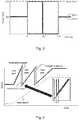
- Figure 3 shows schematically a graph of generator load against time for such a two-stage gear shift and assuming a 200 kW total load.
- Figure 4 shows schematically a graph of rotational speed and output frequency against time for the input shaft 31 and generators 41a, 41b over the gear changes from the low gear ratio 33c, to the mid gear ratio 33b and ending at the high gear ratio 33a.
- a mechanism can be provided to impose predetermined angular relationships between each generator and the input shaft 31 for the different gear ratios 33a-c of each gear shifting arrangement.
- the mechanism may be based on a respective set of dog teeth for each gear ratio of each gear shifting arrangement. If the dog teeth are located on the output shafts, by ensuring that the number of generator poles of each generator is an integer multiple of the number of dog teeth in the sets of dog teeth, the two generators can be kept in phase when they are both driven at the same speed, and hence can share the electrical load on a single airframe electrical bus.
- the gear shifting arrangements may have synchromesh or other speed-matching systems for matching gear speeds when changing the gear ratio.
- the generator system described above allows power to be extracted from the low-pressure spool of a gas turbine, enabling a more highly loaded and more efficient core engine. It also enables generation from this spool without the heat rejection inherent in other variable-speed drive systems that might be used in its place.
- IDGs are 80-90% efficient and continuously variable transmissions (CVTs) are 90-95% efficient, while mechanical gears, such as those used in the generator system described above, can be greater than 99% efficient.
- CVT continuously variable transmissions
- mechanical gears such as those used in the generator system described above.
- the generator system can be made significantly lighter than an equivalently-rated system based on a single generator plus CVT or on an IDG, and without attendant requirements for traction fluid, temperature limitations etc.
- the generator system can achieve these efficiencies without the driveline harshness and power interruption that would be inherent in a system having a single generator which could not be off-loaded during a gear shift.
- a further advantage of the generator system is that the gear shifting arrangement can allow a given generator to be disconnected in case of an internal fault. This can facilitate adoption of permanent magnet generators rather than wound field generators, permanent magnet generators having desirable weight and performance characteristics but suffering from problematic failure scenarios. On disconnection of a faulty permanent magnet generator, the remaining generator can be temporarily overloaded while the aircraft power demand is reduced to a sustainable level (without further gear shifting of the remaining generator), although if necessary both generators can be disconnected.
- Another option for avoiding driveline shock is to input power into or extract power from a generator when it is disconnected from the load to match its speed to the speed of the input. This can be a particularly valuable approach where the generator has large inertia e.g. it is a starter-generator or other motor-generator. Power electronics, variable frequency control, or similar may be used to control the input or extraction of power.
- generators 41a, 41b described above in relation to Figures 2 to 4 are the same size, it is possible for the generators to be of different sizes.
- the generator system described above has two generators, the system may have more than two generators.
- three generators or more permit gear shift ability to be maintained in the event of the failure of one generator.
- the generators of a three generator system could be sized so that each generator provides 1/3 load, or the three generators could each be sized for 1/2 load for full redundancy.
- the generator system can bring benefits where tolerance of a wide input speed range is important, such as in wind or tidal turbines.
Landscapes
- Engineering & Computer Science (AREA)
- Chemical & Material Sciences (AREA)
- Combustion & Propulsion (AREA)
- Mechanical Engineering (AREA)
- General Engineering & Computer Science (AREA)
- Power Engineering (AREA)
- Life Sciences & Earth Sciences (AREA)
- Sustainable Development (AREA)
- Sustainable Energy (AREA)
- Control Of Eletrric Generators (AREA)
Claims (13)
- Stromerzeugersystem, aufweisend:eine Eingangswelle (31) zum Aufnehmen eines rotierenden Eingangsantriebs;mehrere Ausgangswellen (32a, 32b), die mit der Eingangswelle durch entsprechende Schaltanordnungen verbunden sind, wodurch unterschiedliche Übersetzungsverhältnisse (33a-c) zwischen der Eingangswelle und jeder Ausgangswelle bereitgestellt werden; undmehrere elektrische Generatoren (41a, 41b), die durch Rotation der jeweiligen Ausgangswellen angetrieben werden, wobei die elektrischen Leistungen der Generatoren kombiniert werden, um einer Last eine Gesamtleistung zuzuführen;wobei die Eingangswelle über einen Bereich von Rotationsfrequenzen arbeitet und die Schaltanordnungen konfiguriert sind, um die Übersetzungsverhältnisse zwischen der Eingangswelle und den Ausgangswellen so zu verschieben, dass die Ausgangswellen über einen engeren Bereich von Rotationsfrequenzen arbeiten;wobei das System ferner eine Steuerung aufweist, die konfiguriert ist, um die Schaltanordnungen zu steuern, wobei die Steuerung die Übersetzungsverhältnisse der Ausgangswellen ändert, wenn die Rotationsfrequenzen der Ausgangswellen eine Grenze des engeren Bereichs von Rotationsfrequenzen erreichen, indem sie nacheinander die folgenden Schritte ausführt:(i) Trennen eines ausgewählten der Generatoren von der Last derart, dass der verbleibende angeschlossene Generator seine elektrische Leistung erhöht bzw. die verbleibenden angeschlossenen Generatoren ihre elektrischen Leistungen erhöhen, um die Last weiterhin mit der Gesamtleistung zu versorgen,(ii) Ändern des Übersetzungsverhältnisses zwischen der Eingangswelle und der Ausgangswelle des getrennten ausgewählten Generators, so dass sich die Rotationsfrequenz der Ausgangswelle des ausgewählten Generators von der Frequenzgrenze wegbewegt, um innerhalb des engeren Bereichs der Rotationsfrequenzen zu bleiben,(iii) erneutes Anschließen des ausgewählten Generators an die Last und(iv) Wiederholen der Schritte (i) bis (iii) für jeden der anderen Generatoren nacheinander, bis die Übersetzungsverhältnisse der mehreren Generatoren geändert sind.
- Stromerzeugersystem nach Anspruch 1, aufweisend zwei Ausgangswellen und zwei jeweilige elektrische Generatoren oder drei Ausgangswellen und drei jeweilige elektrische Generatoren.
- Stromerzeugersystem nach Anspruch 1 oder 2, wobei jede Schaltanordnung konfiguriert ist, um zwei oder drei unterschiedliche Übersetzungsverhältnisse zwischen der Eingangswelle und der jeweiligen Ausgangswelle bereitzustellen.
- Stromerzeugersystem nach einem der vorhergehenden Ansprüche, wobei die Schaltanordnungen einen Mechanismus zum Auferlegen vorbestimmter Winkelbeziehungen zwischen jedem Generator und der Eingangswelle für die unterschiedlichen Übersetzungsverhältnisse umfassen, die jeder Schaltanordnung zugeordnet sind, wodurch die Generatoren, vor und nach jeder Änderung der Übersetzungsverhältnisse der Abtriebswellen, in Phase miteinander arbeiten.
- Stromerzeugersystem nach Anspruch 4, wobei der Mechanismus entsprechende Sätze von Klauenzähnen für die unterschiedlichen Übersetzungsverhältnisse jeder Schaltanordnung umfasst.
- Stromerzeugersystem nach einem der vorhergehenden Ansprüche, wobei die Schaltanordnungen Geschwindigkeitsanpassungssysteme zum Anpassen von Zahnraddrehzahlen beim Ändern des Übersetzungsverhältnisses aufweisen.
- Stromerzeugersystem nach einem der vorhergehenden Ansprüche, wobei Schritt (ii) das Einspeisen von Leistung in den getrennten ausgewählten Generator oder das Entnehmen von Leistung aus diesem umfasst, um die Drehzahl seiner Ausgangswelle auf Übereinstimmung mit der Änderung des Übersetzungsverhältnisses anzupassen.
- Stromerzeugersystem nach einem der vorhergehenden Ansprüche, wobei die Generatoren Permanentmagnetgeneratoren sind.
- Gasturbinentriebwerk, das ein Stromerzeugersystem nach einem der vorhergehenden Ansprüche aufweist, wobei die Eingangswelle betriebsmäßig mit einer Welle des Triebwerks verbunden ist, um den rotierenden Eingangsantrieb aufzunehmen.
- Gasturbinentriebwerk nach Anspruch 9, das ein Turbofan-Triebwerk ist, die Welle, die betriebsmäßig mit der Eingangswelle verbunden ist, die einen Vortriebsfan des Triebwerks antreibt.
- Gasturbinentriebwerk nach Anspruch 9 oder 10, wobei die Steuerung Teil einer elektronischen Triebwerkssteuerung des Triebwerks ist.
- Verfahren zum Steuern eines Stromerzeugersystems, das aufweist: eine Eingangswelle (31) zum Aufnehmen eines rotierenden Eingangsantriebs;
mehrere Ausgangswellen (32a, 32b), die durch entsprechende Schaltanordnungen mit der Eingangswelle verbunden sind, wodurch unterschiedliche Übersetzungsverhältnisse (33a-c) zwischen der Eingangswelle und jeder Ausgangswelle bereitgestellt werden; und
mehrere elektrische Generatoren (41a, 41b), die durch Rotation der jeweiligen Ausgangswellen angetrieben werden, wobei die elektrischen Leistungen der Generatoren kombiniert werden, um einer Last eine Gesamtleistung zuzuführen;
wobei die Eingangswelle über einen Bereich von Rotationsfrequenzen arbeitet und die Schaltanordnungen konfiguriert sind, um die Übersetzungsverhältnisse zwischen der Eingangswelle und den Ausgangswellen so zu verschieben, dass die Ausgangswellen über einen engeren Bereich von Rotationsfrequenzen arbeiten;
wobei das Verfahren das nacheinander Ausführen der folgenden Schritte umfasst:(i) wenn die Rotationsfrequenzen der Ausgangswellen eine Grenze des engeren Bereichs von Rotationsfrequenzen erreichen, Trennen eines ausgewählten der Generatoren von der Last derart, dass der verbleibende angeschlossene Generator seine elektrische Leistung erhöht bzw. die verbleibenden angeschlossenen Generatoren ihre elektrischen Leistungen erhöhen, um die Last weiterhin mit der Gesamtleistung zu versorgen,(ii) Ändern des Übersetzungsverhältnisses zwischen der Eingangswelle und der Ausgangswelle des getrennten ausgewählten Generators, so dass sich die Rotationsfrequenz der Ausgangswelle des ausgewählten Generators von der Frequenzgrenze wegbewegt, um innerhalb des engeren Bereichs der Rotationsfrequenzen zu bleiben,(iii) erneutes Anschließen des ausgewählten Generators an die Last und(iv) Wiederholen der Schritte (i) bis (iii) für jeden der anderen Generatoren nacheinander, bis die Übersetzungsverhältnisse der mehreren Generatoren geändert sind. - Verfahren nach Anspruch 12, wobei Schritt (ii) das Einspeisen von Leistung in den getrennten ausgewählten Generator oder das Entnehmen von Leistung aus diesem umfasst, um die Drehzahl seiner Ausgangswelle auf Übereinstimmung mit der Änderung des Übersetzungsverhältnisses anzupassen.
Applications Claiming Priority (1)
| Application Number | Priority Date | Filing Date | Title |
|---|---|---|---|
| GBGB1804128.5A GB201804128D0 (en) | 2018-03-15 | 2018-03-15 | Electrical power generator system |
Publications (2)
| Publication Number | Publication Date |
|---|---|
| EP3540198A1 EP3540198A1 (de) | 2019-09-18 |
| EP3540198B1 true EP3540198B1 (de) | 2021-01-27 |
Family
ID=62017793
Family Applications (1)
| Application Number | Title | Priority Date | Filing Date |
|---|---|---|---|
| EP19157651.1A Not-in-force EP3540198B1 (de) | 2018-03-15 | 2019-02-18 | Elektrisches stromerzeugungssystem |
Country Status (4)
| Country | Link |
|---|---|
| US (1) | US10961863B2 (de) |
| EP (1) | EP3540198B1 (de) |
| CN (1) | CN110273757B (de) |
| GB (1) | GB201804128D0 (de) |
Families Citing this family (2)
| Publication number | Priority date | Publication date | Assignee | Title |
|---|---|---|---|---|
| US10900374B1 (en) | 2019-08-13 | 2021-01-26 | Hamilton Sunstrand Corporation | Transmission shift control method for reduced torque transients |
| US11248523B2 (en) | 2019-11-06 | 2022-02-15 | Raytheon Technologies Corporation | Dual clutch transmission for accessory gearbox drive |
Family Cites Families (22)
| Publication number | Priority date | Publication date | Assignee | Title |
|---|---|---|---|---|
| GB1348020A (en) * | 1971-12-20 | 1974-03-13 | Suri M M | Power unit for high speed locomotives |
| US4461957A (en) * | 1982-06-17 | 1984-07-24 | Control Data Corporation | Speed tolerant alternator system for wind or hydraulic power generation |
| US7552582B2 (en) * | 2005-06-07 | 2009-06-30 | Honeywell International Inc. | More electric aircraft power transfer systems and methods |
| US7481062B2 (en) * | 2005-12-30 | 2009-01-27 | Honeywell International Inc. | More electric aircraft starter-generator multi-speed transmission system |
| US7891450B2 (en) * | 2007-02-21 | 2011-02-22 | Ford Global Technologies, Llc | System and method of torque transmission using an electric energy conversion device |
| KR101074696B1 (ko) * | 2008-12-31 | 2011-10-18 | 두산중공업 주식회사 | 풍력발전기의 동력분배형 기어박스 장치 |
| FR2948151B1 (fr) * | 2009-07-17 | 2011-11-25 | Snecma | Procede et systeme pour la commande d'un demarreur-generateur de moteur d'aeronef |
| GB2476261A (en) * | 2009-12-17 | 2011-06-22 | Richard Julius Gozdawa | A gas turbine generator |
| US8561413B2 (en) * | 2010-12-29 | 2013-10-22 | Ge Aviation Systems, Llc | System for powering a vehicle |
| GB201110189D0 (en) * | 2011-06-16 | 2011-08-03 | Rolls Royce Plc | An electrical generation system |
| GB201121428D0 (en) * | 2011-12-14 | 2012-01-25 | Rolls Royce Plc | Controller |
| JP5941744B2 (ja) | 2012-04-27 | 2016-06-29 | 株式会社Ihiエアロスペース | 発電システム |
| US20140008170A1 (en) * | 2012-07-06 | 2014-01-09 | Henry R. Vanderzyden | Integrated drive generator disconnect assembly |
| GB201219916D0 (en) | 2012-11-06 | 2012-12-19 | Rolls Royce Plc | An electrical generation arrangement for an aircraft |
| EP3604764B1 (de) * | 2013-03-07 | 2023-04-19 | Rolls-Royce Corporation | Mehrwellengasturbinentriebwerk |
| WO2014149101A2 (en) * | 2013-03-15 | 2014-09-25 | Rolls-Royce Corporation | Propulsion, electrical, and thermal management device for a small unmanned aerial vehicle |
| GB201308026D0 (en) * | 2013-05-03 | 2013-06-12 | Rolls Royce Plc | Electrical unit with electrical connector |
| EP3467272A1 (de) * | 2013-06-03 | 2019-04-10 | United Technologies Corporation | Getriebearchitektur für den bläserantrieb mittels einer kleinvolumigen und mit hoher geschwindigkeit laufender turbine |
| EP2889452B1 (de) * | 2013-12-30 | 2020-07-22 | Rolls-Royce Corporation | System und Verfahren zur koordinierten Steuerung eines Stromnetzes |
| GB2536878A (en) * | 2015-03-23 | 2016-10-05 | Aurelia Turbines Oy | Multi-spool gas turbine arrangement |
| GB201511033D0 (en) * | 2015-05-19 | 2015-08-05 | Rolls Royce Plc | Aircraft electrical network |
| CN106285945B (zh) * | 2016-10-28 | 2018-04-10 | 清华大学 | 连续旋转爆震发电机 |
-
2018
- 2018-03-15 GB GBGB1804128.5A patent/GB201804128D0/en not_active Ceased
-
2019
- 2019-02-18 EP EP19157651.1A patent/EP3540198B1/de not_active Not-in-force
- 2019-02-27 US US16/286,714 patent/US10961863B2/en active Active
- 2019-03-15 CN CN201910198805.4A patent/CN110273757B/zh not_active Expired - Fee Related
Non-Patent Citations (1)
| Title |
|---|
| None * |
Also Published As
| Publication number | Publication date |
|---|---|
| US10961863B2 (en) | 2021-03-30 |
| US20190284948A1 (en) | 2019-09-19 |
| EP3540198A1 (de) | 2019-09-18 |
| CN110273757B (zh) | 2023-09-05 |
| GB201804128D0 (en) | 2018-05-02 |
| CN110273757A (zh) | 2019-09-24 |
Similar Documents
| Publication | Publication Date | Title |
|---|---|---|
| US11084591B2 (en) | Aircraft cabin blower system having a transmission receiving mechanical power from a first and seccond input wherein the first input is configured to receive mechanical power from a turbine engine and a first electrical machine to configured to receive mechanical power from the turbine engine independent of the transmission | |
| EP3382183B1 (de) | Hilfsgetriebe | |
| US8500583B2 (en) | Aircraft starter generator | |
| US10059460B2 (en) | Method and architecture for the optimized transfer of power between an auxiliary power motor and the main engines of a helicopter | |
| US7791235B2 (en) | Variable magnetic coupling of rotating machinery | |
| US7973422B2 (en) | Device for producing electrical power in a two-spool gas turbine engine | |
| US11591967B2 (en) | Systems and methods for providing mechanical power to an aircraft accessory with a turbine engine | |
| CA2584371A1 (en) | Electric power generation system and method | |
| US20150152783A1 (en) | Combination of two gas turbines to drive a load | |
| EP3540198B1 (de) | Elektrisches stromerzeugungssystem | |
| GB2589193A (en) | Augmented drive of compressors via differential and multistage turbine | |
| EP4119781B1 (de) | Gasturbinentriebwerk und verfahren zum betrieb | |
| EP4477863B1 (de) | Elektrisches starten eines gasturbinenmotors | |
| JP2023539804A (ja) | 機械駆動機器のための駆動装置 | |
| US12116899B2 (en) | Variable speed pumping system with electric pump motor generator | |
| US12584482B1 (en) | Gear pump parallel load path | |
| US11905887B2 (en) | Restarting a gas turbine engine | |
| US20250092850A1 (en) | Integrated gear motor (igm) |
Legal Events
| Date | Code | Title | Description |
|---|---|---|---|
| PUAI | Public reference made under article 153(3) epc to a published international application that has entered the european phase |
Free format text: ORIGINAL CODE: 0009012 |
|
| STAA | Information on the status of an ep patent application or granted ep patent |
Free format text: STATUS: THE APPLICATION HAS BEEN PUBLISHED |
|
| AK | Designated contracting states |
Kind code of ref document: A1 Designated state(s): AL AT BE BG CH CY CZ DE DK EE ES FI FR GB GR HR HU IE IS IT LI LT LU LV MC MK MT NL NO PL PT RO RS SE SI SK SM TR |
|
| AX | Request for extension of the european patent |
Extension state: BA ME |
|
| STAA | Information on the status of an ep patent application or granted ep patent |
Free format text: STATUS: REQUEST FOR EXAMINATION WAS MADE |
|
| 17P | Request for examination filed |
Effective date: 20200109 |
|
| RBV | Designated contracting states (corrected) |
Designated state(s): AL AT BE BG CH CY CZ DE DK EE ES FI FR GB GR HR HU IE IS IT LI LT LU LV MC MK MT NL NO PL PT RO RS SE SI SK SM TR |
|
| RAP1 | Party data changed (applicant data changed or rights of an application transferred) |
Owner name: ROLLS-ROYCE PLC |
|
| GRAP | Despatch of communication of intention to grant a patent |
Free format text: ORIGINAL CODE: EPIDOSNIGR1 |
|
| STAA | Information on the status of an ep patent application or granted ep patent |
Free format text: STATUS: GRANT OF PATENT IS INTENDED |
|
| RIC1 | Information provided on ipc code assigned before grant |
Ipc: F03D 15/00 20160101ALI20200915BHEP Ipc: H02K 7/18 20060101ALI20200915BHEP Ipc: F03D 9/25 20160101ALI20200915BHEP Ipc: F02C 7/36 20060101ALI20200915BHEP Ipc: F02C 7/32 20060101AFI20200915BHEP Ipc: H02K 7/116 20060101ALI20200915BHEP |
|
| INTG | Intention to grant announced |
Effective date: 20201001 |
|
| GRAS | Grant fee paid |
Free format text: ORIGINAL CODE: EPIDOSNIGR3 |
|
| GRAA | (expected) grant |
Free format text: ORIGINAL CODE: 0009210 |
|
| STAA | Information on the status of an ep patent application or granted ep patent |
Free format text: STATUS: THE PATENT HAS BEEN GRANTED |
|
| AK | Designated contracting states |
Kind code of ref document: B1 Designated state(s): AL AT BE BG CH CY CZ DE DK EE ES FI FR GB GR HR HU IE IS IT LI LT LU LV MC MK MT NL NO PL PT RO RS SE SI SK SM TR |
|
| REG | Reference to a national code |
Ref country code: GB Ref legal event code: FG4D |
|
| REG | Reference to a national code |
Ref country code: CH Ref legal event code: EP |
|
| REG | Reference to a national code |
Ref country code: AT Ref legal event code: REF Ref document number: 1358548 Country of ref document: AT Kind code of ref document: T Effective date: 20210215 |
|
| REG | Reference to a national code |
Ref country code: IE Ref legal event code: FG4D |
|
| REG | Reference to a national code |
Ref country code: DE Ref legal event code: R096 Ref document number: 602019002303 Country of ref document: DE |
|
| REG | Reference to a national code |
Ref country code: NL Ref legal event code: MP Effective date: 20210127 |
|
| REG | Reference to a national code |
Ref country code: LT Ref legal event code: MG9D |
|
| REG | Reference to a national code |
Ref country code: AT Ref legal event code: MK05 Ref document number: 1358548 Country of ref document: AT Kind code of ref document: T Effective date: 20210127 |
|
| PG25 | Lapsed in a contracting state [announced via postgrant information from national office to epo] |
Ref country code: BG Free format text: LAPSE BECAUSE OF FAILURE TO SUBMIT A TRANSLATION OF THE DESCRIPTION OR TO PAY THE FEE WITHIN THE PRESCRIBED TIME-LIMIT Effective date: 20210427 Ref country code: GR Free format text: LAPSE BECAUSE OF FAILURE TO SUBMIT A TRANSLATION OF THE DESCRIPTION OR TO PAY THE FEE WITHIN THE PRESCRIBED TIME-LIMIT Effective date: 20210428 Ref country code: FI Free format text: LAPSE BECAUSE OF FAILURE TO SUBMIT A TRANSLATION OF THE DESCRIPTION OR TO PAY THE FEE WITHIN THE PRESCRIBED TIME-LIMIT Effective date: 20210127 Ref country code: HR Free format text: LAPSE BECAUSE OF FAILURE TO SUBMIT A TRANSLATION OF THE DESCRIPTION OR TO PAY THE FEE WITHIN THE PRESCRIBED TIME-LIMIT Effective date: 20210127 Ref country code: NO Free format text: LAPSE BECAUSE OF FAILURE TO SUBMIT A TRANSLATION OF THE DESCRIPTION OR TO PAY THE FEE WITHIN THE PRESCRIBED TIME-LIMIT Effective date: 20210427 Ref country code: PT Free format text: LAPSE BECAUSE OF FAILURE TO SUBMIT A TRANSLATION OF THE DESCRIPTION OR TO PAY THE FEE WITHIN THE PRESCRIBED TIME-LIMIT Effective date: 20210527 Ref country code: LT Free format text: LAPSE BECAUSE OF FAILURE TO SUBMIT A TRANSLATION OF THE DESCRIPTION OR TO PAY THE FEE WITHIN THE PRESCRIBED TIME-LIMIT Effective date: 20210127 |
|
| PG25 | Lapsed in a contracting state [announced via postgrant information from national office to epo] |
Ref country code: SE Free format text: LAPSE BECAUSE OF FAILURE TO SUBMIT A TRANSLATION OF THE DESCRIPTION OR TO PAY THE FEE WITHIN THE PRESCRIBED TIME-LIMIT Effective date: 20210127 Ref country code: AT Free format text: LAPSE BECAUSE OF FAILURE TO SUBMIT A TRANSLATION OF THE DESCRIPTION OR TO PAY THE FEE WITHIN THE PRESCRIBED TIME-LIMIT Effective date: 20210127 Ref country code: RS Free format text: LAPSE BECAUSE OF FAILURE TO SUBMIT A TRANSLATION OF THE DESCRIPTION OR TO PAY THE FEE WITHIN THE PRESCRIBED TIME-LIMIT Effective date: 20210127 Ref country code: LV Free format text: LAPSE BECAUSE OF FAILURE TO SUBMIT A TRANSLATION OF THE DESCRIPTION OR TO PAY THE FEE WITHIN THE PRESCRIBED TIME-LIMIT Effective date: 20210127 Ref country code: PL Free format text: LAPSE BECAUSE OF FAILURE TO SUBMIT A TRANSLATION OF THE DESCRIPTION OR TO PAY THE FEE WITHIN THE PRESCRIBED TIME-LIMIT Effective date: 20210127 |
|
| PG25 | Lapsed in a contracting state [announced via postgrant information from national office to epo] |
Ref country code: IS Free format text: LAPSE BECAUSE OF FAILURE TO SUBMIT A TRANSLATION OF THE DESCRIPTION OR TO PAY THE FEE WITHIN THE PRESCRIBED TIME-LIMIT Effective date: 20210527 |
|
| REG | Reference to a national code |
Ref country code: BE Ref legal event code: MM Effective date: 20210228 |
|
| REG | Reference to a national code |
Ref country code: DE Ref legal event code: R097 Ref document number: 602019002303 Country of ref document: DE |
|
| PG25 | Lapsed in a contracting state [announced via postgrant information from national office to epo] |
Ref country code: SM Free format text: LAPSE BECAUSE OF FAILURE TO SUBMIT A TRANSLATION OF THE DESCRIPTION OR TO PAY THE FEE WITHIN THE PRESCRIBED TIME-LIMIT Effective date: 20210127 Ref country code: MC Free format text: LAPSE BECAUSE OF FAILURE TO SUBMIT A TRANSLATION OF THE DESCRIPTION OR TO PAY THE FEE WITHIN THE PRESCRIBED TIME-LIMIT Effective date: 20210127 Ref country code: LU Free format text: LAPSE BECAUSE OF NON-PAYMENT OF DUE FEES Effective date: 20210218 Ref country code: CZ Free format text: LAPSE BECAUSE OF FAILURE TO SUBMIT A TRANSLATION OF THE DESCRIPTION OR TO PAY THE FEE WITHIN THE PRESCRIBED TIME-LIMIT Effective date: 20210127 Ref country code: EE Free format text: LAPSE BECAUSE OF FAILURE TO SUBMIT A TRANSLATION OF THE DESCRIPTION OR TO PAY THE FEE WITHIN THE PRESCRIBED TIME-LIMIT Effective date: 20210127 |
|
| PG25 | Lapsed in a contracting state [announced via postgrant information from national office to epo] |
Ref country code: DK Free format text: LAPSE BECAUSE OF FAILURE TO SUBMIT A TRANSLATION OF THE DESCRIPTION OR TO PAY THE FEE WITHIN THE PRESCRIBED TIME-LIMIT Effective date: 20210127 Ref country code: SK Free format text: LAPSE BECAUSE OF FAILURE TO SUBMIT A TRANSLATION OF THE DESCRIPTION OR TO PAY THE FEE WITHIN THE PRESCRIBED TIME-LIMIT Effective date: 20210127 Ref country code: RO Free format text: LAPSE BECAUSE OF FAILURE TO SUBMIT A TRANSLATION OF THE DESCRIPTION OR TO PAY THE FEE WITHIN THE PRESCRIBED TIME-LIMIT Effective date: 20210127 |
|
| PLBE | No opposition filed within time limit |
Free format text: ORIGINAL CODE: 0009261 |
|
| STAA | Information on the status of an ep patent application or granted ep patent |
Free format text: STATUS: NO OPPOSITION FILED WITHIN TIME LIMIT |
|
| 26N | No opposition filed |
Effective date: 20211028 |
|
| PG25 | Lapsed in a contracting state [announced via postgrant information from national office to epo] |
Ref country code: ES Free format text: LAPSE BECAUSE OF FAILURE TO SUBMIT A TRANSLATION OF THE DESCRIPTION OR TO PAY THE FEE WITHIN THE PRESCRIBED TIME-LIMIT Effective date: 20210127 Ref country code: IE Free format text: LAPSE BECAUSE OF NON-PAYMENT OF DUE FEES Effective date: 20210218 Ref country code: AL Free format text: LAPSE BECAUSE OF FAILURE TO SUBMIT A TRANSLATION OF THE DESCRIPTION OR TO PAY THE FEE WITHIN THE PRESCRIBED TIME-LIMIT Effective date: 20210127 |
|
| PG25 | Lapsed in a contracting state [announced via postgrant information from national office to epo] |
Ref country code: SI Free format text: LAPSE BECAUSE OF FAILURE TO SUBMIT A TRANSLATION OF THE DESCRIPTION OR TO PAY THE FEE WITHIN THE PRESCRIBED TIME-LIMIT Effective date: 20210127 |
|
| PG25 | Lapsed in a contracting state [announced via postgrant information from national office to epo] |
Ref country code: IT Free format text: LAPSE BECAUSE OF FAILURE TO SUBMIT A TRANSLATION OF THE DESCRIPTION OR TO PAY THE FEE WITHIN THE PRESCRIBED TIME-LIMIT Effective date: 20210127 |
|
| PG25 | Lapsed in a contracting state [announced via postgrant information from national office to epo] |
Ref country code: IS Free format text: LAPSE BECAUSE OF FAILURE TO SUBMIT A TRANSLATION OF THE DESCRIPTION OR TO PAY THE FEE WITHIN THE PRESCRIBED TIME-LIMIT Effective date: 20210527 |
|
| PG25 | Lapsed in a contracting state [announced via postgrant information from national office to epo] |
Ref country code: BE Free format text: LAPSE BECAUSE OF NON-PAYMENT OF DUE FEES Effective date: 20210228 |
|
| REG | Reference to a national code |
Ref country code: CH Ref legal event code: PL |
|
| PG25 | Lapsed in a contracting state [announced via postgrant information from national office to epo] |
Ref country code: LI Free format text: LAPSE BECAUSE OF NON-PAYMENT OF DUE FEES Effective date: 20220228 Ref country code: CH Free format text: LAPSE BECAUSE OF NON-PAYMENT OF DUE FEES Effective date: 20220228 |
|
| PG25 | Lapsed in a contracting state [announced via postgrant information from national office to epo] |
Ref country code: NL Free format text: LAPSE BECAUSE OF NON-PAYMENT OF DUE FEES Effective date: 20210127 Ref country code: CY Free format text: LAPSE BECAUSE OF FAILURE TO SUBMIT A TRANSLATION OF THE DESCRIPTION OR TO PAY THE FEE WITHIN THE PRESCRIBED TIME-LIMIT Effective date: 20210127 |
|
| P01 | Opt-out of the competence of the unified patent court (upc) registered |
Effective date: 20230528 |
|
| PG25 | Lapsed in a contracting state [announced via postgrant information from national office to epo] |
Ref country code: HU Free format text: LAPSE BECAUSE OF FAILURE TO SUBMIT A TRANSLATION OF THE DESCRIPTION OR TO PAY THE FEE WITHIN THE PRESCRIBED TIME-LIMIT; INVALID AB INITIO Effective date: 20190218 |
|
| PG25 | Lapsed in a contracting state [announced via postgrant information from national office to epo] |
Ref country code: MK Free format text: LAPSE BECAUSE OF FAILURE TO SUBMIT A TRANSLATION OF THE DESCRIPTION OR TO PAY THE FEE WITHIN THE PRESCRIBED TIME-LIMIT Effective date: 20210127 |
|
| PGFP | Annual fee paid to national office [announced via postgrant information from national office to epo] |
Ref country code: DE Payment date: 20240228 Year of fee payment: 6 Ref country code: GB Payment date: 20240220 Year of fee payment: 6 |
|
| PGFP | Annual fee paid to national office [announced via postgrant information from national office to epo] |
Ref country code: FR Payment date: 20240226 Year of fee payment: 6 |
|
| PG25 | Lapsed in a contracting state [announced via postgrant information from national office to epo] |
Ref country code: MT Free format text: LAPSE BECAUSE OF FAILURE TO SUBMIT A TRANSLATION OF THE DESCRIPTION OR TO PAY THE FEE WITHIN THE PRESCRIBED TIME-LIMIT Effective date: 20210127 |
|
| REG | Reference to a national code |
Ref country code: DE Ref legal event code: R119 Ref document number: 602019002303 Country of ref document: DE |
|
| GBPC | Gb: european patent ceased through non-payment of renewal fee |
Effective date: 20250218 |
|
| PG25 | Lapsed in a contracting state [announced via postgrant information from national office to epo] |
Ref country code: TR Free format text: LAPSE BECAUSE OF FAILURE TO SUBMIT A TRANSLATION OF THE DESCRIPTION OR TO PAY THE FEE WITHIN THE PRESCRIBED TIME-LIMIT Effective date: 20210127 |
|
| PG25 | Lapsed in a contracting state [announced via postgrant information from national office to epo] |
Ref country code: DE Free format text: LAPSE BECAUSE OF NON-PAYMENT OF DUE FEES Effective date: 20250902 |
|
| PG25 | Lapsed in a contracting state [announced via postgrant information from national office to epo] |
Ref country code: GB Free format text: LAPSE BECAUSE OF NON-PAYMENT OF DUE FEES Effective date: 20250218 |
|
| PG25 | Lapsed in a contracting state [announced via postgrant information from national office to epo] |
Ref country code: FR Free format text: LAPSE BECAUSE OF NON-PAYMENT OF DUE FEES Effective date: 20250228 |