EP3382183B1 - Hilfsgetriebe - Google Patents
Hilfsgetriebe Download PDFInfo
- Publication number
- EP3382183B1 EP3382183B1 EP18165485.6A EP18165485A EP3382183B1 EP 3382183 B1 EP3382183 B1 EP 3382183B1 EP 18165485 A EP18165485 A EP 18165485A EP 3382183 B1 EP3382183 B1 EP 3382183B1
- Authority
- EP
- European Patent Office
- Prior art keywords
- input
- accessory
- differential
- rotational energy
- pump
- Prior art date
- Legal status (The legal status is an assumption and is not a legal conclusion. Google has not performed a legal analysis and makes no representation as to the accuracy of the status listed.)
- Active
Links
Images

Classifications
-
- F—MECHANICAL ENGINEERING; LIGHTING; HEATING; WEAPONS; BLASTING
- F02—COMBUSTION ENGINES; HOT-GAS OR COMBUSTION-PRODUCT ENGINE PLANTS
- F02C—GAS-TURBINE PLANTS; AIR INTAKES FOR JET-PROPULSION PLANTS; CONTROLLING FUEL SUPPLY IN AIR-BREATHING JET-PROPULSION PLANTS
- F02C7/00—Features, components parts, details or accessories, not provided for in, or of interest apart form groups F02C1/00 - F02C6/00; Air intakes for jet-propulsion plants
- F02C7/32—Arrangement, mounting, or driving, of auxiliaries
-
- F—MECHANICAL ENGINEERING; LIGHTING; HEATING; WEAPONS; BLASTING
- F01—MACHINES OR ENGINES IN GENERAL; ENGINE PLANTS IN GENERAL; STEAM ENGINES
- F01D—NON-POSITIVE DISPLACEMENT MACHINES OR ENGINES, e.g. STEAM TURBINES
- F01D15/00—Adaptations of machines or engines for special use; Combinations of engines with devices driven thereby
- F01D15/08—Adaptations for driving, or combinations with, pumps
-
- F—MECHANICAL ENGINEERING; LIGHTING; HEATING; WEAPONS; BLASTING
- F01—MACHINES OR ENGINES IN GENERAL; ENGINE PLANTS IN GENERAL; STEAM ENGINES
- F01D—NON-POSITIVE DISPLACEMENT MACHINES OR ENGINES, e.g. STEAM TURBINES
- F01D15/00—Adaptations of machines or engines for special use; Combinations of engines with devices driven thereby
- F01D15/12—Combinations with mechanical gearing
-
- F—MECHANICAL ENGINEERING; LIGHTING; HEATING; WEAPONS; BLASTING
- F02—COMBUSTION ENGINES; HOT-GAS OR COMBUSTION-PRODUCT ENGINE PLANTS
- F02C—GAS-TURBINE PLANTS; AIR INTAKES FOR JET-PROPULSION PLANTS; CONTROLLING FUEL SUPPLY IN AIR-BREATHING JET-PROPULSION PLANTS
- F02C7/00—Features, components parts, details or accessories, not provided for in, or of interest apart form groups F02C1/00 - F02C6/00; Air intakes for jet-propulsion plants
- F02C7/36—Power transmission arrangements between the different shafts of the gas turbine plant, or between the gas-turbine plant and the power user
-
- F—MECHANICAL ENGINEERING; LIGHTING; HEATING; WEAPONS; BLASTING
- F16—ENGINEERING ELEMENTS AND UNITS; GENERAL MEASURES FOR PRODUCING AND MAINTAINING EFFECTIVE FUNCTIONING OF MACHINES OR INSTALLATIONS; THERMAL INSULATION IN GENERAL
- F16H—GEARING
- F16H37/00—Combinations of mechanical gearings, not provided for in groups F16H1/00 - F16H35/00
- F16H37/02—Combinations of mechanical gearings, not provided for in groups F16H1/00 - F16H35/00 comprising essentially only toothed or friction gearings
- F16H37/06—Combinations of mechanical gearings, not provided for in groups F16H1/00 - F16H35/00 comprising essentially only toothed or friction gearings with a plurality of driving or driven shafts; with arrangements for dividing torque between two or more intermediate shafts
- F16H37/08—Combinations of mechanical gearings, not provided for in groups F16H1/00 - F16H35/00 comprising essentially only toothed or friction gearings with a plurality of driving or driven shafts; with arrangements for dividing torque between two or more intermediate shafts with differential gearing
- F16H37/0806—Combinations of mechanical gearings, not provided for in groups F16H1/00 - F16H35/00 comprising essentially only toothed or friction gearings with a plurality of driving or driven shafts; with arrangements for dividing torque between two or more intermediate shafts with differential gearing with a plurality of driving or driven shafts
-
- F—MECHANICAL ENGINEERING; LIGHTING; HEATING; WEAPONS; BLASTING
- F01—MACHINES OR ENGINES IN GENERAL; ENGINE PLANTS IN GENERAL; STEAM ENGINES
- F01D—NON-POSITIVE DISPLACEMENT MACHINES OR ENGINES, e.g. STEAM TURBINES
- F01D25/00—Component parts, details, or accessories, not provided for in, or of interest apart from, other groups
- F01D25/18—Lubricating arrangements
- F01D25/20—Lubricating arrangements using lubrication pumps
-
- F—MECHANICAL ENGINEERING; LIGHTING; HEATING; WEAPONS; BLASTING
- F01—MACHINES OR ENGINES IN GENERAL; ENGINE PLANTS IN GENERAL; STEAM ENGINES
- F01D—NON-POSITIVE DISPLACEMENT MACHINES OR ENGINES, e.g. STEAM TURBINES
- F01D5/00—Blades; Blade-carrying members; Heating, heat-insulating, cooling or antivibration means on the blades or the members
- F01D5/02—Blade-carrying members, e.g. rotors
-
- F—MECHANICAL ENGINEERING; LIGHTING; HEATING; WEAPONS; BLASTING
- F02—COMBUSTION ENGINES; HOT-GAS OR COMBUSTION-PRODUCT ENGINE PLANTS
- F02C—GAS-TURBINE PLANTS; AIR INTAKES FOR JET-PROPULSION PLANTS; CONTROLLING FUEL SUPPLY IN AIR-BREATHING JET-PROPULSION PLANTS
- F02C3/00—Gas-turbine plants characterised by the use of combustion products as the working fluid
- F02C3/04—Gas-turbine plants characterised by the use of combustion products as the working fluid having a turbine driving a compressor
-
- F—MECHANICAL ENGINEERING; LIGHTING; HEATING; WEAPONS; BLASTING
- F02—COMBUSTION ENGINES; HOT-GAS OR COMBUSTION-PRODUCT ENGINE PLANTS
- F02C—GAS-TURBINE PLANTS; AIR INTAKES FOR JET-PROPULSION PLANTS; CONTROLLING FUEL SUPPLY IN AIR-BREATHING JET-PROPULSION PLANTS
- F02C7/00—Features, components parts, details or accessories, not provided for in, or of interest apart form groups F02C1/00 - F02C6/00; Air intakes for jet-propulsion plants
- F02C7/22—Fuel supply systems
-
- F—MECHANICAL ENGINEERING; LIGHTING; HEATING; WEAPONS; BLASTING
- F04—POSITIVE - DISPLACEMENT MACHINES FOR LIQUIDS; PUMPS FOR LIQUIDS OR ELASTIC FLUIDS
- F04D—NON-POSITIVE-DISPLACEMENT PUMPS
- F04D29/00—Details, component parts, or accessories
- F04D29/26—Rotors specially for elastic fluids
- F04D29/32—Rotors specially for elastic fluids for axial flow pumps
- F04D29/321—Rotors specially for elastic fluids for axial flow pumps for axial flow compressors
-
- F—MECHANICAL ENGINEERING; LIGHTING; HEATING; WEAPONS; BLASTING
- F05—INDEXING SCHEMES RELATING TO ENGINES OR PUMPS IN VARIOUS SUBCLASSES OF CLASSES F01-F04
- F05D—INDEXING SCHEME FOR ASPECTS RELATING TO NON-POSITIVE-DISPLACEMENT MACHINES OR ENGINES, GAS-TURBINES OR JET-PROPULSION PLANTS
- F05D2220/00—Application
- F05D2220/30—Application in turbines
- F05D2220/32—Application in turbines in gas turbines
-
- F—MECHANICAL ENGINEERING; LIGHTING; HEATING; WEAPONS; BLASTING
- F05—INDEXING SCHEMES RELATING TO ENGINES OR PUMPS IN VARIOUS SUBCLASSES OF CLASSES F01-F04
- F05D—INDEXING SCHEME FOR ASPECTS RELATING TO NON-POSITIVE-DISPLACEMENT MACHINES OR ENGINES, GAS-TURBINES OR JET-PROPULSION PLANTS
- F05D2260/00—Function
- F05D2260/40—Transmission of power
- F05D2260/403—Transmission of power through the shape of the drive components
- F05D2260/4031—Transmission of power through the shape of the drive components as in toothed gearing
- F05D2260/40311—Transmission of power through the shape of the drive components as in toothed gearing of the epicyclical, planetary or differential type
-
- F—MECHANICAL ENGINEERING; LIGHTING; HEATING; WEAPONS; BLASTING
- F16—ENGINEERING ELEMENTS AND UNITS; GENERAL MEASURES FOR PRODUCING AND MAINTAINING EFFECTIVE FUNCTIONING OF MACHINES OR INSTALLATIONS; THERMAL INSULATION IN GENERAL
- F16H—GEARING
- F16H37/00—Combinations of mechanical gearings, not provided for in groups F16H1/00 - F16H35/00
- F16H37/02—Combinations of mechanical gearings, not provided for in groups F16H1/00 - F16H35/00 comprising essentially only toothed or friction gearings
- F16H37/06—Combinations of mechanical gearings, not provided for in groups F16H1/00 - F16H35/00 comprising essentially only toothed or friction gearings with a plurality of driving or driven shafts; with arrangements for dividing torque between two or more intermediate shafts
- F16H37/08—Combinations of mechanical gearings, not provided for in groups F16H1/00 - F16H35/00 comprising essentially only toothed or friction gearings with a plurality of driving or driven shafts; with arrangements for dividing torque between two or more intermediate shafts with differential gearing
- F16H37/0806—Combinations of mechanical gearings, not provided for in groups F16H1/00 - F16H35/00 comprising essentially only toothed or friction gearings with a plurality of driving or driven shafts; with arrangements for dividing torque between two or more intermediate shafts with differential gearing with a plurality of driving or driven shafts
- F16H37/0826—Combinations of mechanical gearings, not provided for in groups F16H1/00 - F16H35/00 comprising essentially only toothed or friction gearings with a plurality of driving or driven shafts; with arrangements for dividing torque between two or more intermediate shafts with differential gearing with a plurality of driving or driven shafts with only one output shaft
-
- F—MECHANICAL ENGINEERING; LIGHTING; HEATING; WEAPONS; BLASTING
- F16—ENGINEERING ELEMENTS AND UNITS; GENERAL MEASURES FOR PRODUCING AND MAINTAINING EFFECTIVE FUNCTIONING OF MACHINES OR INSTALLATIONS; THERMAL INSULATION IN GENERAL
- F16H—GEARING
- F16H48/00—Differential gearings
- F16H48/06—Differential gearings with gears having orbital motion
- F16H48/08—Differential gearings with gears having orbital motion comprising bevel gears
Definitions
- the present disclosure relates to power transmission, and more particular to mechanical power transmission between gas turbines and gas turbine engine accessories.
- Gas turbine engines such as in aircraft, commonly employ gearboxes to transfer a portion of the rotating energy generated by the engine core to various accessory loads coupled to the engine through the gearbox.
- the loads impose drag on the engine core, which requires that the engine operate with sufficient margin to overcome the drag.
- Examples of accessory loads requiring mechanical power include fuel pumps, fuel flow governors, hydraulic pumps, oil pumps, pneumatic valves, engine actuators, tachometers, generators, etc.
- the gearbox transferring the mechanical power generally employs reduction gearing.
- the reduction gearing receives high speed rotation from the core, reduces the rotational speed to speed suitable for engine accessories and communicates the mechanical power as rotation to the accessories.
- the size of the reduction gearing generally increases with rotational speed mismatch of the core and accessory loads, greater mismatches requiring larger reduction gearing and/or limiting rotational speed of the engine core.
- Gearboxes are taught in US 5,694,765 , US 2010/024424 , US 2007/173365 and GB 2197392 .
- An accessory gearbox for a gas turbine engine is provided as defined in claim 1.
- a fuel pump can be connected to the first differential.
- the pump motor can be operatively coupled to the fuel pump through the first differential.
- An oil pump can be coupled to the first differential.
- the first input and the second input can be operatively coupled to the oil pump through the first differential.
- the first differential can include first and second spider gears.
- the spider gears can be coaxial with a pump motor shaft and arranged along an axis coaxial with the first input and orthogonal to the second input.
- the accessory gearbox can include a second differential.
- the second differential can be connected to the second input.
- the second input can include a coupling arranged for selective connection of the accessory gear train to a gas turbine engine high speed spool.
- the coupling can include a clutch, a brake, or a clutch and brake arrangement.
- the second differential can couple the second input to the accessory gear train.
- a generator can be connected to the second differential.
- the generator can be a starter/generator.
- the first input and the second input can be operably coupled by the second differential to the generator.
- the second differential can include first and second spider gears.
- the spider gears can be coaxial with the second input and arranged along an axis orthogonal to the first input.
- an auxiliary oil pump and a hydraulic pump can be connected to the accessory gear train.
- the first and second inputs can be operably coupled to the auxiliary oil pump and the hydraulic pump through the accessory gear train.
- the first differential can communicate rotational energy to the hydraulic pump and the auxiliary oil pump from a gas turbine engine low speed spool.
- the second differential can communicate rotational energy to the hydraulic pump and the auxiliary oil pump from a gas turbine engine high speed spool.
- the accessory gearbox includes a pump differential.
- the pump differential is coupled to a pump motor by the first differential.
- An oil pump tune motor is connected to the pump differential and operatively coupled therethrough to the oil pump.
- the pump differential includes first and second spider gears.
- the spider gears can be coaxial with an oil pump shaft and arranged along an axis orthogonal relative to the first input and parallel relative to the second input.
- a gas turbine engine includes an accessory gearbox as described above with a first differential and a second differential.
- the first differential is connected to the first input and couples therethrough the first input to the accessory gear train.
- the second differential is connected to second input and couples therethrough the second input to the accessory gear train.
- a high speed spool is coupled to the first differential by the first input, a low speed spool coupled to the second differential by the second input, and the first and second differentials are arranged to combine rotational energy received spools for powering one or more accessories mounted to the accessory gearbox.
- a method of communicating rotational energy between a gas turbine engine and one or more gas turbine engine accessories is provided in claim 10.
- FIG. 1 a partial view of an exemplary embodiment of an accessory gearbox in accordance with the disclosure is shown in Fig. 1 and is designated generally by reference character 100.
- Other embodiments of accessory gearboxes, gas turbine engines, and methods of communicating rotational energy between gas turbine engines and engine accessories in accordance with the disclosure, or aspects thereof, are provided in Figs. 2-4 , as will be described.
- the systems and methods described herein can be used in gas turbine engines, such as geared turbofan engines, though the present disclosure is not limited to geared turbofan engines or to turbofan engines in general.
- Gas turbine engine 10 includes a fan section 12, a compressor section 14, a combustor section 16, a turbine section 18, and accessory gearbox 100 with an engine accessory mounted thereto.
- Fan section 12 drives air along a bypass flow path B in a bypass duct defined within fan section 12.
- Compressor section 14 drives air along a core flow path C for compression and communication therethrough to combustor section 16 and turbine section 18.
- Compressor section 14 includes a low pressure compressor 20 and a high pressure compressor 22 arranged along a rotation axis A.
- Turbine section 18 includes a high pressure turbine 24 and a low pressure turbine 26 arranged along rotation axis A.
- Low pressure compressor 20 and low pressure turbine 26 are connected to one another as a low speed spool 28, and rotate in concert with one another about rotation axis A.
- High pressure compressor 22 and high pressure turbine 24 are connected to one another as a high speed spool 32, and rotate in concert with one another about rotation axis A.
- low speed spool 28 and high speed spool 32 rotate at different rotational speeds about rotation axis A, e.g., at a high speed spool rotational speed R 2 that is greater than a low speed rotational speed R 1 , as appropriate for a given operating regime of gas turbine engine 10.
- Low pressure compressor 20 is arranged axially downstream of fan section 12 and receives therefrom air from the ambient environment. Low pressure compressor 20 compresses the air received from fan section 12 and provides the compressed air to high pressure compressor 22. High pressure compressor 22 further compresses the air received from low pressure compressor 20 and communicates the compressed air to combustor section 16. Combustor section 16 generates high pressure combustion products using an ignited mixture of compressed and injected high-pressure atomized fuel, and communicates the combustion products to turbine section 18.
- Turbine section 18 expands the high pressure combustion products received from combustor section 16, extracts work therefrom, and applies the extracted work to high speed spool 32 and low speed spool 28 as rotational energy.
- Low speed spool 28 and high speed spool 32 use the their respective rotational energies to drive low pressure compressor 20, high pressure compressor 22 respectively, and one or more accessories mounted to accessory gearbox 100 coupled to low speed spool 28 and high speed spool 32 therethrough.
- rotational energy supplied by gas turbine engines to engine accessories is typically provided by a takeoff shaft driven by the high speed spool, generally through intervening reduction gearing. While generally satisfactory for its intended purpose, it can sometimes be undesirable to power engine accessories from the high speed spool.
- powering accessories using the high speed spool can require that the high speed spool be larger than otherwise necessary and/or be rotated at a slower speed than otherwise required for efficient engine operation. This is because drag (or load) associated with engine accessories like generators has grown with the advent of more-electric aircraft architectures while gas turbine engines increasingly employ smaller cores that run at higher rotational speeds for engine thermodynamic efficiency purposes.
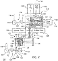
- Accessory gearbox 100 includes an accessory gear train 102, a first input 104, and a second input 106.
- First input 104 couples low speed spool 28 to accessory gear train 102 for communicating rotational energy between low speed spool 28 and accessory gear train 102.
- Second input 106 couples high speed spool 32 to accessory gear train 102 for communicating rotational energy between high speed spool 32 and accessory gear train 102.
- Accessory gear train 102 couples first input 104 with second input 106 for communicating rotational energy between either or both low speed spool 28 and high speed spool 32 and accessories coupled to thereto by accessory gear train 102.
- First input 104 includes a radial drive shaft 108, a bevel gear set 110, and a lay shaft 112 for communicating rotational energy R 1 between low speed spool 28 (shown in Fig. 1 ) and accessory gear train 102.
- Radial drive shaft 108 is connected between low speed spool 26 and bevel gear set 110.
- Lay shaft 112 is connected between bevel gear set 110 and accessory gearbox 100, and is received in a first differential 116 of accessory gearbox 100 along a first input axis 114.
- Second input 106 includes a radial drive shaft 118, bevel gear set 120, an intermediate shaft 122, bevel gear set 124, and a lay shaft 126 for communicating rotational energy R 2 between high speed spool 32 (shown in Fig. 1 ) and accessory gearbox 100.
- Radial drive shaft 118 is connected between high speed spool 32 and bevel gear set 120.
- Intermediate shaft 122 is connected between bevel gear set 120 and bevel gear set 124.
- Lay shaft 126 is connected between bevel gear set 124 and accessory gearbox 100 and is received within a second differential 130 of accessory gearbox 100 along a second input axis 128.
- Second input axis 128 is orthogonal relative to first input axis 114.
- First differential 116 has a carrier 132, a first spider gear 134, a second spider gear 136, a side gear 138, a ring gear 140, and an accessory gear 142.
- Carrier 132 is supported for rotation relative to accessory gearbox 100.
- First spider gear 134 is fixed relative to lay shaft 112, is coaxial with a pump motor shaft 139, and is supported for rotation relative to carrier 132 first input axis 114.
- Second spider gear 136 is fixed relative to a pump motor shaft 139, is supported for rotation relative to carrier 132, and is coupled to first spider gear 134 by intermeshed side gear 138.
- Second gear 138 is supported for rotation within carrier 132 about a side gear axis 146, which is orthogonal relative to first input axis 114, and intermeshes with first spider gear 134 and second spider gear 136.
- Ring gear 140 is fixed relative to carrier 132 and is operably connected to a fuel pump 148 and an oil pump 150. In the illustrated exemplary embodiment rotational energy is communicated from first differential 116 to oil pump 150 through fuel pump 148 via intermeshed pinion gears coupled to respective shafts of fuel pump 148 and oil pump 150.
- Accessory gear 142 is fixed in rotation relative to lay shaft 112 and intermeshes with accessory gear train 102.
- accessory gear train 102 includes a first gear 162 and a second gear 164, first gear 162 intermeshing with accessory gear 142 and second gear 164 being coupled to second differential 130.
- An auxiliary pump 168 and a hydraulic pump 166 are each connected to first gear 162, first differential 116 and second differential 130 being operatively coupled to auxiliary pump 168 and hydraulic pump 166 through first gear 162 to provide rotational energy thereto.
- Second differential 130 is similar to first differential 116 with the difference that it is clocked 90 degrees relative to first differential 116, and includes a carrier 174, a first spider gear 176, a second spider gear 178, a side gear 180, and a ring gear 182.
- Carrier 174 is supported for rotation relative to accessory gearbox 100.
- First spider gear 176 is fixed relative to second lay shaft 126 and is supported for rotation relative to carrier 174.
- Second spider gear 178 is coaxial with lay shaft 126, is supported for rotation relative to carrier 174, and is coupled to accessory gear train 102 by an intermediate bevel gear set and shafting.
- Side gear 180 is supported for rotation within carrier 174 and about a side gear axis, which is orthogonal relative to lay shaft 126, and intermeshes with first spider gear 176 and second spider gear 178.
- Ring gear 182 is fixed relative to carrier 174 and is operatively coupled to a generator 156, which is mounted to second differential 130.
- Generator 156 can be, by way of non-limiting example, a starter/generator arranged to provide and receive rotational energy through accessory gearbox 100.
- a pump motor 158 mount to first differential 116 at pump motor shaft 139.
- Pump motor 158 is operably coupled to fuel pump 148 and oil pump 150 through first differential 116 to provide rotational energy to fuel pump 148 and oil pump 150 in additional to that provided by low speed spool 28 and high speed spool 32. This allows for providing increased oil and/or fuel flow using fuel pump 148 and oil pump 150, such was when increased cooling is required for hot engine components and/or generator 156, and is otherwise not readily available from low speed spool 28 (shown in Fig. 1 ) and high speed spool 32 (shown in Fig. 1 ).
- second input 106 can include a coupling 184 for selective connection of accessory gearbox 100 with high speed spool 32 and/or braking.
- coupling 184 can include a disconnect 184A, which be a clutch-type device.
- Coupling 184 can include a brake 184B.
- coupling 184 can include both disconnect and a brake.
- Coupling 184 can be hydraulic, electro-magnetic, or any other kind of coupling as suitable for an intended application. It is contemplated that coupling 184 can be operatively connected to an engine control arrangement (not show for clarity reasons), such as Electronic Engine Control (EEC) and Full Authority Digital Engine Control (FADEC).
- EEC Electronic Engine Control
- FADEC Full Authority Digital Engine Control
- coupling 184 is arranged along intermediate shaft 122 for selective connecting and disconnect accessory gearbox 100 from radial drive shaft 118, and therethrough from high speed spool 32 (shown in Fig. 1 ).
- coupling 184 can be arranged to connect generator 156 through second input 106 to high speed spool 32 (shown in Fig. 1 ) of gas turbine engine 10. Connection of generator 156 through coupling 184 allows generator 156 to communicate rotational energy to high speed spool 32 to enable gas turbine engine 10 to start.
- the rotational resistance presented to generator 156 through second differential second spider gear 178 is such that substantially all rotational energy provided by generator 156 flows to high speed spool 32, the accessory load effectively rotational fixing second spider gear 180 relative to first spider gear 176 such that the rotational energy flows through second input 106.
- coupling 184 is actuated to disconnect second input 106 from accessory gearbox 100, ceasing application of rotational energy through second input 106 for starting gas turbine engine 10. Disconnecting second input 106 from gas turbine engine 10 once ground ide rotational speed is reached reduces losses that could otherwise be realized through continuous connection (and hence, power take-off) of accessory gearbox 100 with high speed spool 32 (shown in Fig. 1 ).
- Disconnecting second input 106 from gas turbine engine 10 once ground idle rotational speed also allows high speed spool 32 to reach a higher rotational speed, e.g., a thermally more optimal rotational speed, once free of the mechanical load exerted by accessory gearbox 100 through second input 106.
- coupling 184 can be actuated to reconnect accessory gearbox 100 to high speed spool 32 after landing of the aircraft in preparation of the next engine start.
- coupling 184 can additionally provide the capability the connect/disconnect accessory gearbox 100 for maintenance operations, such as ground inspections, maintenance, compressor washing, etc.
- coupling 184 further provides the capability to connect or disconnect accessory gearbox 100 during flight, simplifying in-flight engine re-start in the unlikely event that gas turbine engine 10 becomes inoperable.
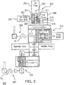
- Accessory gearbox 200 is similar to accessory gearbox 100 (shown in Fig. 2 ) and additionally includes a pump differential 201 and an oil pump tune motor 203.
- Pump differential 201 is similar to first differential 116 (shown in Fig. 2 ) and is additionally clocked differently that first differential 116 and second differential 130 (shown in Fig. 2 ).
- pump differential 201 be a relatively small differential, e.g., less massive than first differential 216 and second differential 230.
- An oil pump tune motor 203 is coupled to an oil pump 250 through pump differential 201. This allows for operating oil pump 250 with rotational energy provided by oil pump tune motor 250 to supplement rotational energy provided by first input 204 and/or second input 206 through first differential 216 and second differential 230. It is also contemplated that oil pump tune motor 203 provide rotational energy to oil pump 250 when rotational energy is unavailable from first input 204 and/or second input 206, such as during engine starting. As will be appreciated by those of skill in art in view of the present disclosure, oil pump tune motor 203 can be arranged to preferentially communicate rotational energy provided by oil pump motor 203 to oil pump 250 by sizing the intervening elements such that more resistance is seen at pinion gear 217 than at oil pump 250.
- Pump differential 201 has a carrier 207, a first spider gear 209, a second spider gear 211, a side gear 213, a ring gear 215, and pinion gear 217, which can be a bull gear.
- Carrier 207 is supported for rotation relative to accessory gearbox 200.
- First spider gear 209 is fixed relative to pinion gear 217 and is supported for rotation relative to carrier 207.
- Second spider gear 211 is fixed relative to oil pump shaft 252, is coaxial with a first spider gear 209, and is supported for rotation relative to carrier 207.
- Side gear 213 is supported for rotation within carrier 207 about a side gear axis 219, which is orthogonal relative to oil pump shaft 252, and intermeshes with first spider gear 209 and second spider gear 211.
- Ring gear 215 is coupled to an oil pump tune motor shaft 221, oil pump tune motor 203 being operatively connected to oil pump 250 through ring gear 215 and pump differential 201 for providing supplemental rotational energy to oil pump 250.
- Accessory gearbox 200 is configured to provide pressurized oil using oil pump 250 and fuel pump 248 using oil pump tune motor 203.
- oil pump tune motor 203 can provide rotational energy to oil pump 250 such that pressurized oil is provided to gas turbine engine 10 (shown in Fig. 1 ) during engine start-up.
- pressurizing lubricant during startup simplifies starting as it reduces resistance to rotation of high speed spool 32 (shown in Fig. 1 ), allowing a smaller starter to be employed for rotating high speed spool 32 up to the ground idle minimum rotational speed.
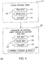
- Method 300 includes receiving rotational energy at an accessory gearbox, e.g., accessory gearbox 100 (shown in Fig. 1 ), as shown with box 310. It is contemplated that the rotational energy can be received from a plurality of sources.
- rotational energy can be received from dual inputs.
- rotational energy can be received from a first input, e.g., first input 104 (shown in Fig. 2 ), as shown with box 312.
- rotational energy can be received from the second input, e.g., second input 106 (shown in Fig. 2 ), as shown with box 314.
- Rotational energy can be received from the accessory, e.g., pump motor 158 (shown in Fig. 2 ), generator 156 (shown in Fig. 2 ), and/or an oil pump tube motor 203 (shown in Fig. 3 ), as shown with box 316.
- the rotational can be received from two or more of the first input, second input and accessory such as from a low speed spool, e.g., low speed spool 28 (shown in Fig. 2 ), and a high speed spool, e.g., high speed spool 32 (shown in Fig. 2 ), as shown with bracket 318.
- a low speed spool e.g., low speed spool 28 (shown in Fig. 2 )
- a high speed spool e.g., high speed spool 32 (shown in Fig. 2 ), as shown with bracket 318.
- the rotational energy can be communicated through an accessory gear train, e.g. accessory gear train 102 (shown in Fig. 2 ), as shown with box 320.
- the rotational energy can be communicated to the first input and/or the second input, as shown with box 322 and 324.
- the rotational energy can be communicated to an engine accessory, as shown with box 326.
- Rotational energy from two or more of the first input and the second input can be combined by the accessory gearbox and thereafter provided to the engine accessory, as shown with box 328.
- Rotational energy can be selectively communicated through the accessory gearbox, as shown with bracket 330. For example, rotational energy from the generator can be applied to the second input only, such as during engine startup.
- the drag from the accessories on the differentials coupled to first input allow the second input to spin as a result of the applied torque from the starter/generator.
- the spinning of the first input can add additional energy to the starter input thus allowing engine to re-start.
- Rotational energy from both the first and second inputs can be applied to the engine accessories. Rotation either the first input or the second input can be applied to the engine accessories.
- accessory gearboxes have a first input to provide rotational energy for powering accessories mounted to the accessory gearbox.
- the first input can connect the engine low speed spool to the accessory gearbox, reducing the load carried by the high speed spool connected to the accessory gearbox by a second input owing to the rotational power available from the low speed spool.
- rotational energy available from the high speed spool may be insufficient for the generator to meet the electrical power required to actuate flight control surfaces, deploy spoilers, extend the aircraft landing gear, and deploy the engine thrust reversers subsequent to touch down.
- Coupling the generator to the engine low speed spool through accessory gearbox via first and second differentials and first input can provide the rotational energy necessary to meet these electrical power requirements using the engine low speed spool. It can also reduce the drag exerted on the engine high speed spool by the generator, enabling engine architectures with relatively small high speed spools and/or spools which rotate at relatively high rotational speeds as well as more electric aircraft architectures requiring greater amounts of electrical power generating capability.
- accessory gearboxes described herein enable the pump motor mounted to the accessory gearbox through the first differential to provide rotational power to the fuel pump and oil pump during engine start.
- Rotational power can also be provided to the fuel pump and oil pump from the pump motor to the fuel pump and oil pump during transient flight regimes, such as the beginning of descent, where the rotational speed of high speed spool is relatively low due to reduced engine thrust requirements during descent.
- the pump motor can configured to provide a subtractive speed bias to reduce pump speed during cruise at altitude to reduce unnecessary flow and pressure output as well as waste heat created by the oil pump and/or fuel pump, thereby reducing the need to dissipate heat through the engine heat exchanger(s) or to communicate waste heat into engine lubricant or fuel flows.
- accessory gearboxes described herein can include a relatively small pump differential.
- the pump differential can have a bull gear intermeshed with the fuel pump input shaft and therethrough coupled to the accessory gearbox second differential.
- the oil pump can mount to the accessory gearbox at the pump differential, the pump differential providing rotational energy to the oil pump at a differential speed input.
- a relatively small/lightweight electric tune motor can be mounted to the accessory gearbox at the pump differential.
- the tune motor can provide a more accurate oil pump speed control which can adjusted, i.e. tuned, independent of rotational speeds of the low speed spool and high speed spool of the engine. Independent speed adjustment capability provided by the tune motor allows the oil pump speed to be increased or decreased as appropriate to improve oil flow and thermal management within the gas turbine engine, potentially reducing the size of the heat exchanger(s) employed by the engine oil and fuel systems and/or eliminating the variable oil reduction valve (VORV) and associated plumbing required in certain engine architectures.
- VORV variable oil reduction valve
Landscapes
- Engineering & Computer Science (AREA)
- General Engineering & Computer Science (AREA)
- Chemical & Material Sciences (AREA)
- Combustion & Propulsion (AREA)
- Mechanical Engineering (AREA)
- Retarders (AREA)
Claims (10)
- Hilfsgetriebe für ein Gasturbinentriebwerk, umfassend:einen Hilfsgetriebezug;einen ersten Eingang (204), der an den Hilfsgetriebezug gekoppelt ist;einen zweiten Eingang (206), der an den Hilfsgetriebezug gekoppelt ist, wobei der Hilfsgetriebezug den ersten Eingang und den zweiten Eingang wirkkoppelt, um Drehenergie zwischen einem Zubehör, das an dem Hilfsgetriebe montiert ist, und dem ersten und dem zweiten Eingang zu kommunizieren;ein erstes Differential (216), das mit dem ersten Eingang verbunden ist und den ersten Eingang an den Hilfsgetriebezug koppelt;einen Pumpenmotor;ein Pumpendifferential (201), das durch das erste Differential an den Pumpenmotor gekoppelt ist;eine Ölpumpe (250), die eine Ölpumpenwelle (252) aufweist; undeinen Ölpumpenabstimmungsmotor (203), der mit dem Pumpendifferential verbunden und dadurch an die Ölpumpe wirkgekoppelt ist;wobei das Pumpendifferential ein erstes (209) und ein zweites (211) Spinnengetriebe beinhaltet, die entlang der Ölpumpenwelle angeordnet sind, wobei die Ölpumpenwelle zur Drehung entlang einer Achse orthogonal zu dem ersten Eingang und parallel zu dem zweiten Eingang gestützt wird.
- Hilfsgetriebe nach Anspruch 1, ferner umfassend eine Kraftstoffpumpe (248), die mit dem ersten Differential verbunden ist, wobei der Pumpenmotor durch das erste Differential an die Kraftstoffpumpe wirkgekoppelt ist.
- Hilfsgetriebe nach Anspruch 1 oder 2, wobei die Ölpumpe (250) mit dem ersten Differential verbunden und dadurch an den ersten Eingang und den zweiten Eingang gekoppelt ist.
- Hilfsgetriebe nach einem vorhergehenden Anspruch, wobei der Pumpenmotor eine Pumpenmotorwelle aufweist und wobei das erste Differential ein erstes und ein zweites Spinnengetriebe koaxial mit der Pumpenmotorwelle beinhaltet, wobei die Pumpenmotorwelle koaxial mit dem ersten Eingang und orthogonal zu dem zweiten Eingang ist.
- Hilfsgetriebe nach einem vorhergehenden Anspruch, ferner umfassend ein zweites Differential (230), das mit dem zweiten Eingang verbunden und dadurch an den Hilfsgetriebezug gekoppelt ist,
und wobei das zweite Differential bevorzugt ein erstes und ein zweites Spinnengetriebe koaxial mit dem zweiten Eingang und orthogonal relativ zu dem ersten Eingang beinhaltet. - Hilfsgetriebe nach Anspruch 5, ferner umfassend einen Generator, der mit dem zweiten Differential verbunden ist, wobei der erste Eingang und der zweite Eingang durch das zweite Differential an den Generator wirkgekoppelt sind.
- Hilfsgetriebe nach einem vorhergehenden Anspruch, ferner umfassend eine Hilfsölpumpe und eine Hydraulikpumpe, die mit dem Hilfsgetriebezug verbunden ist, wobei der erste Eingang und der zweite Eingang durch den Hilfsgetriebezug an die Hilfsölpumpe und die Hydraulikpumpe wirkgekoppelt sind.
- Hilfsgetriebe nach Anspruch 7, wobei das erste Differential den ersten Eingang und den Hilfsgetriebezug verbindet und konfiguriert ist, um Drehenergie an die Hydraulikpumpe und die Hilfsölpumpe von einer Niedergeschwindigkeitsspule eines Gasturbinentriebwerks zu kommunizieren, oder ferner umfassend ein zweites Differential, das den zweiten Eingang und den Hilfsgetriebezug verbindet und konfiguriert ist, um Drehenergie an die Hydraulikpumpe und die Hilfsölpumpe von einer Hochgeschwindigkeitsspule eines Gasturbinentriebwerks zu kommunizieren.
- Gasturbinentriebwerk, umfassend:ein Hilfsgetriebe (200) nach einem vorhergehenden Anspruch, wobei das Hilfsgetriebe das erste Differential, das mit dem ersten Eingang verbunden ist und dadurch den ersten Eingang an den Hilfsgetriebezug koppelt, und ein zweites Differential umfasst, das mit dem zweiten Eingang verbunden ist und dadurch den zweiten Eingang an den Hilfsgetriebezug koppelt;eine Niedergeschwindigkeitsspule (28), die durch den ersten Eingang an das erste Differential gekoppelt ist; undeine Hochgeschwindigkeitsspule (32), die durch den zweiten Eingang an das zweite Differential gekoppelt ist, wobei das erste und das zweite Differential konfiguriert sind, um Drehenergie zu kombinieren, die dadurch empfangen wird, um ein oder mehrere Zubehöre anzutreiben, die an dem Hilfsgetriebe montiert sind.
- Verfahren zum Kommunizieren von Drehenergie zwischen einem Gasturbinentriebwerk und einem oder mehreren Gasturbinentriebwerkszubehören, umfassend:Empfangen von Drehenergie an einem Hilfsgetriebe nach Anspruch 1-8; undselektives Kommunizieren der Drehenergie durch einen Hilfsgetriebezug an eines oder mehrere von dem ersten Eingang, dem zweiten Eingang und dem Triebwerkszubehör,wobei das Empfangen von Drehenergie das Empfangen von Drehenergie von dem ersten Eingang und dem zweiten Eingang umfasst, wobei das selektive Kommunizieren der Drehenergie das selektive Kommunizieren der Drehenergie an das Triebwerkszubehör umfasst, oder wobei das Empfangen von Drehenergie das Empfangen von Drehenergie von dem Triebwerkszubehör umfasst, wobei das selektive Kommunizieren der Drehenergie das selektive Kommunizieren der Drehenergie an den zweiten Eingang umfasst oder wobei das Empfangen von Drehenergie das Empfangen von Drehenergie nur von dem ersten Eingang umfasst, wobei das selektive Kommunizieren der Drehenergie das selektive Kommunizieren der Drehenergie an Triebwerkszubehör umfasst.
Applications Claiming Priority (1)
| Application Number | Priority Date | Filing Date | Title |
|---|---|---|---|
| US15/476,319 US20180283281A1 (en) | 2017-03-31 | 2017-03-31 | Accessory gearboxes |
Publications (2)
| Publication Number | Publication Date |
|---|---|
| EP3382183A1 EP3382183A1 (de) | 2018-10-03 |
| EP3382183B1 true EP3382183B1 (de) | 2020-05-13 |
Family
ID=62027774
Family Applications (1)
| Application Number | Title | Priority Date | Filing Date |
|---|---|---|---|
| EP18165485.6A Active EP3382183B1 (de) | 2017-03-31 | 2018-04-03 | Hilfsgetriebe |
Country Status (2)
| Country | Link |
|---|---|
| US (1) | US20180283281A1 (de) |
| EP (1) | EP3382183B1 (de) |
Cited By (1)
| Publication number | Priority date | Publication date | Assignee | Title |
|---|---|---|---|---|
| EP4148253A1 (de) * | 2021-09-08 | 2023-03-15 | Rolls-Royce North American Technologies, Inc. | Redundantes elektrisch angetriebenes brennstoff- und ölpumpensystem für gasturbinen mit bidirektionalem pumpenmotor |
Families Citing this family (33)
| Publication number | Priority date | Publication date | Assignee | Title |
|---|---|---|---|---|
| FR3044044B1 (fr) * | 2015-11-19 | 2021-01-29 | Snecma | Systeme d'alimentation en fluide d'au moins un organe d'un ensemble propulsif d'aeronef |
| US10883424B2 (en) | 2016-07-19 | 2021-01-05 | Pratt & Whitney Canada Corp. | Multi-spool gas turbine engine architecture |
| US11415063B2 (en) | 2016-09-15 | 2022-08-16 | Pratt & Whitney Canada Corp. | Reverse-flow gas turbine engine |
| US11035293B2 (en) | 2016-09-15 | 2021-06-15 | Pratt & Whitney Canada Corp. | Reverse flow gas turbine engine with offset RGB |
| US10465611B2 (en) | 2016-09-15 | 2019-11-05 | Pratt & Whitney Canada Corp. | Reverse flow multi-spool gas turbine engine with aft-end accessory gearbox drivingly connected to both high pressure spool and low pressure spool |
| US10815899B2 (en) | 2016-11-15 | 2020-10-27 | Pratt & Whitney Canada Corp. | Gas turbine engine accessories arrangement |
| US10808624B2 (en) | 2017-02-09 | 2020-10-20 | Pratt & Whitney Canada Corp. | Turbine rotor with low over-speed requirements |
| US10746188B2 (en) | 2017-03-14 | 2020-08-18 | Pratt & Whitney Canada Corp. | Inter-shaft bearing connected to a compressor boost system |
| US10526976B2 (en) * | 2017-04-27 | 2020-01-07 | United Technologies Corporation | Tangential drive for gas turbine engine accessories |
| KR20190021577A (ko) * | 2017-08-23 | 2019-03-06 | 한화파워시스템 주식회사 | 고효율 발전 시스템 |
| US10731566B2 (en) | 2017-10-18 | 2020-08-04 | Honeywell International Inc. | Compact accessory systems for a gas turbine engine |
| CN109866613B (zh) * | 2017-12-04 | 2020-11-03 | 华为技术有限公司 | 减速器、电动汽车的驱动系统及其控制方法、电动汽车 |
| US10823081B2 (en) * | 2017-12-21 | 2020-11-03 | Raytheon Technologies Corporation | Concentric power takeoff transmission |
| CN110821677A (zh) | 2018-08-08 | 2020-02-21 | 普拉特 - 惠特尼加拿大公司 | 多发动机系统和方法 |
| US11168577B2 (en) * | 2018-10-24 | 2021-11-09 | Hamilton Sundstrand Corporation | Gearbox ratio change |
| US11719164B2 (en) * | 2018-12-06 | 2023-08-08 | Raytheon Technologies Corporation | Conformal accessory gearbox for low bypass gas turbine engine |
| FR3092617B1 (fr) * | 2019-02-12 | 2022-07-08 | Safran Aircraft Engines | Ensemble comprenant un boitier d’accessoires pour une turbomachine |
| US11428164B2 (en) * | 2019-02-21 | 2022-08-30 | Rolls-Royce Corporation | Gas turbine engine with scalable pumping system |
| US20200300168A1 (en) * | 2019-03-20 | 2020-09-24 | United Technologies Corporation | Backup system for demand fuel pumping system |
| EP3734046B1 (de) | 2019-05-02 | 2024-11-13 | RTX Corporation | Differentialgetriebeanordnung mit hochdruckwelle und niederdruckwelle |
| US11193425B2 (en) * | 2019-06-19 | 2021-12-07 | Raytheon Technologies Corporation | Gearbox for boost spool turbine engine |
| FR3099203B1 (fr) * | 2019-07-26 | 2021-07-16 | Safran Aircraft Engines | Circuit de lubrification d’une turbomachine d’aeronef |
| FR3099319B1 (fr) | 2019-07-26 | 2021-06-25 | Safran Aircraft Engines | Turbomachine comprenant une machine électrique ayant une fonction de démarreur-générateur et procédé de régulation de la vitesse d’une telle machine électrique |
| FR3099202B1 (fr) | 2019-07-26 | 2021-07-09 | Safran Aircraft Engines | Dispositif à répartition de puissance entre un démarreur électrique et une machine électrique vers un arbre d’une turbomachine |
| FR3118483B1 (fr) | 2020-12-28 | 2024-02-16 | Safran Aircraft Engines | Module de turbomachine equipe d’une machine electrique et turbomachine equipee d’un tel module |
| CN113883254B (zh) * | 2021-10-26 | 2023-06-23 | 南通睿动新能源科技有限公司 | 一种双电机纯电动减速箱防吸空系统 |
| US12331625B2 (en) * | 2021-11-18 | 2025-06-17 | Yantai Jereh Petroleum Equipment & Technologies Co., Ltd. | Turbine fracturing apparatus and turbine fracturing well site |
| CN114151205B (zh) * | 2021-12-08 | 2022-12-27 | 中国航发南方工业有限公司 | 附件传动装置及具有其的发动机 |
| CN116857085B (zh) * | 2023-06-30 | 2026-01-02 | 南京航空航天大学 | 一种基于轴孔进气的行星齿轮减速传动轴扇发动机构型 |
| US12253029B2 (en) * | 2023-08-07 | 2025-03-18 | Hamilton Sundstrand Corporation | Fuel system for dual use gas turbine engine main fuel pump |
| FR3161927A1 (fr) | 2024-05-03 | 2025-11-07 | Safran Transmission Systems | Ensemble comportant un boitier d’accessoires et des equipements pour une turbomachine d’aeronef |
| US12540579B2 (en) * | 2024-05-03 | 2026-02-03 | Rtx Corporation | Remote mounted accessory gearbox |
| US12372032B1 (en) * | 2024-08-01 | 2025-07-29 | Rtx Corporation | Gas turbine engine with controlled return of fuel to power accessories and retrofitting method |
Family Cites Families (8)
| Publication number | Priority date | Publication date | Assignee | Title |
|---|---|---|---|---|
| JPS63159627A (ja) * | 1986-11-03 | 1988-07-02 | ゼネラル・エレクトリック・カンパニイ | 多重スプール型タービンエンジン用の差動式電力装置 |
| US5039281A (en) * | 1989-12-26 | 1991-08-13 | General Electric Company | Method and apparatus for supplying compressed air to auxiliary systems of a vehicle |
| GB9313905D0 (en) * | 1993-07-06 | 1993-08-25 | Rolls Royce Plc | Shaft power transfer in gas turbine engines |
| FR2892456B1 (fr) * | 2005-10-21 | 2008-01-04 | Hispano Suiza Sa | Dispositif d'entrainement de machines accessoires d'un moteur a turbine a gaz |
| GB0805177D0 (en) * | 2008-03-20 | 2008-04-30 | Rolls Royce Plc | A gas turbine engine arrangement |
| US9062611B2 (en) * | 2011-10-19 | 2015-06-23 | United Technologies Corporation | Split accessory drive system |
| US20140090386A1 (en) * | 2012-09-28 | 2014-04-03 | United Technologies Corporation | Geared turbofan with fan and core mounted accessory gearboxes |
| US10273883B2 (en) * | 2016-02-26 | 2019-04-30 | The Boeing Company | Engine accessory drives systems and methods |
-
2017
- 2017-03-31 US US15/476,319 patent/US20180283281A1/en not_active Abandoned
-
2018
- 2018-04-03 EP EP18165485.6A patent/EP3382183B1/de active Active
Non-Patent Citations (1)
| Title |
|---|
| None * |
Cited By (2)
| Publication number | Priority date | Publication date | Assignee | Title |
|---|---|---|---|---|
| EP4148253A1 (de) * | 2021-09-08 | 2023-03-15 | Rolls-Royce North American Technologies, Inc. | Redundantes elektrisch angetriebenes brennstoff- und ölpumpensystem für gasturbinen mit bidirektionalem pumpenmotor |
| US11702990B2 (en) | 2021-09-08 | 2023-07-18 | Rolls-Royce North American Technologies Inc. | Redundant electrically driven fuel and oil pumping system for gas turbine with bidirectional pump motor |
Also Published As
| Publication number | Publication date |
|---|---|
| US20180283281A1 (en) | 2018-10-04 |
| EP3382183A1 (de) | 2018-10-03 |
Similar Documents
| Publication | Publication Date | Title |
|---|---|---|
| EP3382183B1 (de) | Hilfsgetriebe | |
| US11846237B2 (en) | Gas turbine engine with intercooled cooling air and dual towershaft accessory gearbox | |
| US9328667B2 (en) | Systems and methods for changing a speed of a compressor boost stage in a gas turbine | |
| US10302018B2 (en) | Gas turbine engine geared compressor with first and second input rotors | |
| EP2128389B1 (de) | Gasturbinenmotoranordnung | |
| CA2844186C (en) | Gas turbine engine with transmission and method of adjusting rotational speed | |
| US7882691B2 (en) | High to low pressure spool summing gearbox for accessory power extraction and electric start | |
| US10422243B2 (en) | Gas turbine engine dual towershaft accessory gearbox and starter generator assembly | |
| EP2553251B1 (de) | Adaptives lüftersystem für einen turbofanlüfter mit variablem zyklus | |
| EP3910174B1 (de) | Gegenstromgasturbinentriebwerk mit elektromotor | |
| EP3957843A1 (de) | Hybrid-gasturbinentriebwerk mit elektromotor und stromgenerator | |
| EP3282093A1 (de) | Getriebeturbolüfter mit niederdruckleistungsextraktion | |
| EP4177449B1 (de) | Hilfsgetriebe mit überlagerungsgetriebe | |
| EP4215737B1 (de) | Doppelspulenleistungsextraktion mit überlagerungsgetriebe |
Legal Events
| Date | Code | Title | Description |
|---|---|---|---|
| PUAI | Public reference made under article 153(3) epc to a published international application that has entered the european phase |
Free format text: ORIGINAL CODE: 0009012 |
|
| STAA | Information on the status of an ep patent application or granted ep patent |
Free format text: STATUS: THE APPLICATION HAS BEEN PUBLISHED |
|
| AK | Designated contracting states |
Kind code of ref document: A1 Designated state(s): AL AT BE BG CH CY CZ DE DK EE ES FI FR GB GR HR HU IE IS IT LI LT LU LV MC MK MT NL NO PL PT RO RS SE SI SK SM TR |
|
| AX | Request for extension of the european patent |
Extension state: BA ME |
|
| STAA | Information on the status of an ep patent application or granted ep patent |
Free format text: STATUS: REQUEST FOR EXAMINATION WAS MADE |
|
| 17P | Request for examination filed |
Effective date: 20190403 |
|
| RBV | Designated contracting states (corrected) |
Designated state(s): AL AT BE BG CH CY CZ DE DK EE ES FI FR GB GR HR HU IE IS IT LI LT LU LV MC MK MT NL NO PL PT RO RS SE SI SK SM TR |
|
| GRAP | Despatch of communication of intention to grant a patent |
Free format text: ORIGINAL CODE: EPIDOSNIGR1 |
|
| STAA | Information on the status of an ep patent application or granted ep patent |
Free format text: STATUS: GRANT OF PATENT IS INTENDED |
|
| GRAS | Grant fee paid |
Free format text: ORIGINAL CODE: EPIDOSNIGR3 |
|
| INTG | Intention to grant announced |
Effective date: 20200305 |
|
| GRAA | (expected) grant |
Free format text: ORIGINAL CODE: 0009210 |
|
| STAA | Information on the status of an ep patent application or granted ep patent |
Free format text: STATUS: THE PATENT HAS BEEN GRANTED |
|
| AK | Designated contracting states |
Kind code of ref document: B1 Designated state(s): AL AT BE BG CH CY CZ DE DK EE ES FI FR GB GR HR HU IE IS IT LI LT LU LV MC MK MT NL NO PL PT RO RS SE SI SK SM TR |
|
| REG | Reference to a national code |
Ref country code: GB Ref legal event code: FG4D |
|
| REG | Reference to a national code |
Ref country code: CH Ref legal event code: EP |
|
| REG | Reference to a national code |
Ref country code: DE Ref legal event code: R096 Ref document number: 602018004363 Country of ref document: DE |
|
| REG | Reference to a national code |
Ref country code: AT Ref legal event code: REF Ref document number: 1270589 Country of ref document: AT Kind code of ref document: T Effective date: 20200615 |
|
| REG | Reference to a national code |
Ref country code: LT Ref legal event code: MG4D |
|
| REG | Reference to a national code |
Ref country code: NL Ref legal event code: MP Effective date: 20200513 |
|
| PG25 | Lapsed in a contracting state [announced via postgrant information from national office to epo] |
Ref country code: FI Free format text: LAPSE BECAUSE OF FAILURE TO SUBMIT A TRANSLATION OF THE DESCRIPTION OR TO PAY THE FEE WITHIN THE PRESCRIBED TIME-LIMIT Effective date: 20200513 Ref country code: LT Free format text: LAPSE BECAUSE OF FAILURE TO SUBMIT A TRANSLATION OF THE DESCRIPTION OR TO PAY THE FEE WITHIN THE PRESCRIBED TIME-LIMIT Effective date: 20200513 Ref country code: IS Free format text: LAPSE BECAUSE OF FAILURE TO SUBMIT A TRANSLATION OF THE DESCRIPTION OR TO PAY THE FEE WITHIN THE PRESCRIBED TIME-LIMIT Effective date: 20200913 Ref country code: SE Free format text: LAPSE BECAUSE OF FAILURE TO SUBMIT A TRANSLATION OF THE DESCRIPTION OR TO PAY THE FEE WITHIN THE PRESCRIBED TIME-LIMIT Effective date: 20200513 Ref country code: GR Free format text: LAPSE BECAUSE OF FAILURE TO SUBMIT A TRANSLATION OF THE DESCRIPTION OR TO PAY THE FEE WITHIN THE PRESCRIBED TIME-LIMIT Effective date: 20200814 Ref country code: NO Free format text: LAPSE BECAUSE OF FAILURE TO SUBMIT A TRANSLATION OF THE DESCRIPTION OR TO PAY THE FEE WITHIN THE PRESCRIBED TIME-LIMIT Effective date: 20200813 Ref country code: PT Free format text: LAPSE BECAUSE OF FAILURE TO SUBMIT A TRANSLATION OF THE DESCRIPTION OR TO PAY THE FEE WITHIN THE PRESCRIBED TIME-LIMIT Effective date: 20200914 |
|
| PG25 | Lapsed in a contracting state [announced via postgrant information from national office to epo] |
Ref country code: RS Free format text: LAPSE BECAUSE OF FAILURE TO SUBMIT A TRANSLATION OF THE DESCRIPTION OR TO PAY THE FEE WITHIN THE PRESCRIBED TIME-LIMIT Effective date: 20200513 Ref country code: HR Free format text: LAPSE BECAUSE OF FAILURE TO SUBMIT A TRANSLATION OF THE DESCRIPTION OR TO PAY THE FEE WITHIN THE PRESCRIBED TIME-LIMIT Effective date: 20200513 Ref country code: LV Free format text: LAPSE BECAUSE OF FAILURE TO SUBMIT A TRANSLATION OF THE DESCRIPTION OR TO PAY THE FEE WITHIN THE PRESCRIBED TIME-LIMIT Effective date: 20200513 Ref country code: BG Free format text: LAPSE BECAUSE OF FAILURE TO SUBMIT A TRANSLATION OF THE DESCRIPTION OR TO PAY THE FEE WITHIN THE PRESCRIBED TIME-LIMIT Effective date: 20200813 |
|
| REG | Reference to a national code |
Ref country code: AT Ref legal event code: MK05 Ref document number: 1270589 Country of ref document: AT Kind code of ref document: T Effective date: 20200513 |
|
| PG25 | Lapsed in a contracting state [announced via postgrant information from national office to epo] |
Ref country code: NL Free format text: LAPSE BECAUSE OF FAILURE TO SUBMIT A TRANSLATION OF THE DESCRIPTION OR TO PAY THE FEE WITHIN THE PRESCRIBED TIME-LIMIT Effective date: 20200513 Ref country code: AL Free format text: LAPSE BECAUSE OF FAILURE TO SUBMIT A TRANSLATION OF THE DESCRIPTION OR TO PAY THE FEE WITHIN THE PRESCRIBED TIME-LIMIT Effective date: 20200513 |
|
| PG25 | Lapsed in a contracting state [announced via postgrant information from national office to epo] |
Ref country code: ES Free format text: LAPSE BECAUSE OF FAILURE TO SUBMIT A TRANSLATION OF THE DESCRIPTION OR TO PAY THE FEE WITHIN THE PRESCRIBED TIME-LIMIT Effective date: 20200513 Ref country code: SM Free format text: LAPSE BECAUSE OF FAILURE TO SUBMIT A TRANSLATION OF THE DESCRIPTION OR TO PAY THE FEE WITHIN THE PRESCRIBED TIME-LIMIT Effective date: 20200513 Ref country code: EE Free format text: LAPSE BECAUSE OF FAILURE TO SUBMIT A TRANSLATION OF THE DESCRIPTION OR TO PAY THE FEE WITHIN THE PRESCRIBED TIME-LIMIT Effective date: 20200513 Ref country code: DK Free format text: LAPSE BECAUSE OF FAILURE TO SUBMIT A TRANSLATION OF THE DESCRIPTION OR TO PAY THE FEE WITHIN THE PRESCRIBED TIME-LIMIT Effective date: 20200513 Ref country code: IT Free format text: LAPSE BECAUSE OF FAILURE TO SUBMIT A TRANSLATION OF THE DESCRIPTION OR TO PAY THE FEE WITHIN THE PRESCRIBED TIME-LIMIT Effective date: 20200513 Ref country code: RO Free format text: LAPSE BECAUSE OF FAILURE TO SUBMIT A TRANSLATION OF THE DESCRIPTION OR TO PAY THE FEE WITHIN THE PRESCRIBED TIME-LIMIT Effective date: 20200513 Ref country code: AT Free format text: LAPSE BECAUSE OF FAILURE TO SUBMIT A TRANSLATION OF THE DESCRIPTION OR TO PAY THE FEE WITHIN THE PRESCRIBED TIME-LIMIT Effective date: 20200513 Ref country code: CZ Free format text: LAPSE BECAUSE OF FAILURE TO SUBMIT A TRANSLATION OF THE DESCRIPTION OR TO PAY THE FEE WITHIN THE PRESCRIBED TIME-LIMIT Effective date: 20200513 |
|
| REG | Reference to a national code |
Ref country code: DE Ref legal event code: R097 Ref document number: 602018004363 Country of ref document: DE |
|
| PG25 | Lapsed in a contracting state [announced via postgrant information from national office to epo] |
Ref country code: PL Free format text: LAPSE BECAUSE OF FAILURE TO SUBMIT A TRANSLATION OF THE DESCRIPTION OR TO PAY THE FEE WITHIN THE PRESCRIBED TIME-LIMIT Effective date: 20200513 Ref country code: SK Free format text: LAPSE BECAUSE OF FAILURE TO SUBMIT A TRANSLATION OF THE DESCRIPTION OR TO PAY THE FEE WITHIN THE PRESCRIBED TIME-LIMIT Effective date: 20200513 |
|
| PLBE | No opposition filed within time limit |
Free format text: ORIGINAL CODE: 0009261 |
|
| STAA | Information on the status of an ep patent application or granted ep patent |
Free format text: STATUS: NO OPPOSITION FILED WITHIN TIME LIMIT |
|
| 26N | No opposition filed |
Effective date: 20210216 |
|
| PG25 | Lapsed in a contracting state [announced via postgrant information from national office to epo] |
Ref country code: SI Free format text: LAPSE BECAUSE OF FAILURE TO SUBMIT A TRANSLATION OF THE DESCRIPTION OR TO PAY THE FEE WITHIN THE PRESCRIBED TIME-LIMIT Effective date: 20200513 |
|
| PG25 | Lapsed in a contracting state [announced via postgrant information from national office to epo] |
Ref country code: MC Free format text: LAPSE BECAUSE OF FAILURE TO SUBMIT A TRANSLATION OF THE DESCRIPTION OR TO PAY THE FEE WITHIN THE PRESCRIBED TIME-LIMIT Effective date: 20200513 |
|
| PG25 | Lapsed in a contracting state [announced via postgrant information from national office to epo] |
Ref country code: LU Free format text: LAPSE BECAUSE OF NON-PAYMENT OF DUE FEES Effective date: 20210403 |
|
| REG | Reference to a national code |
Ref country code: BE Ref legal event code: MM Effective date: 20210430 |
|
| PG25 | Lapsed in a contracting state [announced via postgrant information from national office to epo] |
Ref country code: LI Free format text: LAPSE BECAUSE OF NON-PAYMENT OF DUE FEES Effective date: 20210430 Ref country code: CH Free format text: LAPSE BECAUSE OF NON-PAYMENT OF DUE FEES Effective date: 20210430 |
|
| PG25 | Lapsed in a contracting state [announced via postgrant information from national office to epo] |
Ref country code: IE Free format text: LAPSE BECAUSE OF NON-PAYMENT OF DUE FEES Effective date: 20210403 |
|
| PG25 | Lapsed in a contracting state [announced via postgrant information from national office to epo] |
Ref country code: BE Free format text: LAPSE BECAUSE OF NON-PAYMENT OF DUE FEES Effective date: 20210430 |
|
| P01 | Opt-out of the competence of the unified patent court (upc) registered |
Effective date: 20230522 |
|
| PG25 | Lapsed in a contracting state [announced via postgrant information from national office to epo] |
Ref country code: CY Free format text: LAPSE BECAUSE OF FAILURE TO SUBMIT A TRANSLATION OF THE DESCRIPTION OR TO PAY THE FEE WITHIN THE PRESCRIBED TIME-LIMIT Effective date: 20200513 |
|
| PG25 | Lapsed in a contracting state [announced via postgrant information from national office to epo] |
Ref country code: HU Free format text: LAPSE BECAUSE OF FAILURE TO SUBMIT A TRANSLATION OF THE DESCRIPTION OR TO PAY THE FEE WITHIN THE PRESCRIBED TIME-LIMIT; INVALID AB INITIO Effective date: 20180403 |
|
| PG25 | Lapsed in a contracting state [announced via postgrant information from national office to epo] |
Ref country code: MK Free format text: LAPSE BECAUSE OF FAILURE TO SUBMIT A TRANSLATION OF THE DESCRIPTION OR TO PAY THE FEE WITHIN THE PRESCRIBED TIME-LIMIT Effective date: 20200513 |
|
| PG25 | Lapsed in a contracting state [announced via postgrant information from national office to epo] |
Ref country code: TR Free format text: LAPSE BECAUSE OF FAILURE TO SUBMIT A TRANSLATION OF THE DESCRIPTION OR TO PAY THE FEE WITHIN THE PRESCRIBED TIME-LIMIT Effective date: 20200513 |
|
| PG25 | Lapsed in a contracting state [announced via postgrant information from national office to epo] |
Ref country code: MT Free format text: LAPSE BECAUSE OF FAILURE TO SUBMIT A TRANSLATION OF THE DESCRIPTION OR TO PAY THE FEE WITHIN THE PRESCRIBED TIME-LIMIT Effective date: 20200513 |
|
| PGFP | Annual fee paid to national office [announced via postgrant information from national office to epo] |
Ref country code: DE Payment date: 20250319 Year of fee payment: 8 |
|
| PGFP | Annual fee paid to national office [announced via postgrant information from national office to epo] |
Ref country code: GB Payment date: 20260319 Year of fee payment: 9 |
|
| PGFP | Annual fee paid to national office [announced via postgrant information from national office to epo] |
Ref country code: FR Payment date: 20260320 Year of fee payment: 9 |