EP3539834B1 - Hitzeschild für flugzeugbremse - Google Patents
Hitzeschild für flugzeugbremse Download PDFInfo
- Publication number
- EP3539834B1 EP3539834B1 EP19162337.0A EP19162337A EP3539834B1 EP 3539834 B1 EP3539834 B1 EP 3539834B1 EP 19162337 A EP19162337 A EP 19162337A EP 3539834 B1 EP3539834 B1 EP 3539834B1
- Authority
- EP
- European Patent Office
- Prior art keywords
- layer
- shield
- insulation layer
- heat shield
- structure portion
- Prior art date
- Legal status (The legal status is an assumption and is not a legal conclusion. Google has not performed a legal analysis and makes no representation as to the accuracy of the status listed.)
- Active
Links
Images

Classifications
-
- F—MECHANICAL ENGINEERING; LIGHTING; HEATING; WEAPONS; BLASTING
- F16—ENGINEERING ELEMENTS AND UNITS; GENERAL MEASURES FOR PRODUCING AND MAINTAINING EFFECTIVE FUNCTIONING OF MACHINES OR INSTALLATIONS; THERMAL INSULATION IN GENERAL
- F16D—COUPLINGS FOR TRANSMITTING ROTATION; CLUTCHES; BRAKES
- F16D55/00—Brakes with substantially-radial braking surfaces pressed together in axial direction, e.g. disc brakes
- F16D55/24—Brakes with substantially-radial braking surfaces pressed together in axial direction, e.g. disc brakes with a plurality of axially-movable discs, lamellae, or pads, pressed from one side towards an axially-located member
- F16D55/26—Brakes with substantially-radial braking surfaces pressed together in axial direction, e.g. disc brakes with a plurality of axially-movable discs, lamellae, or pads, pressed from one side towards an axially-located member without self-tightening action
- F16D55/36—Brakes with a plurality of rotating discs all lying side by side
-
- F—MECHANICAL ENGINEERING; LIGHTING; HEATING; WEAPONS; BLASTING
- F16—ENGINEERING ELEMENTS AND UNITS; GENERAL MEASURES FOR PRODUCING AND MAINTAINING EFFECTIVE FUNCTIONING OF MACHINES OR INSTALLATIONS; THERMAL INSULATION IN GENERAL
- F16D—COUPLINGS FOR TRANSMITTING ROTATION; CLUTCHES; BRAKES
- F16D65/00—Parts or details
- F16D65/78—Features relating to cooling
- F16D65/84—Features relating to cooling for disc brakes
-
- B—PERFORMING OPERATIONS; TRANSPORTING
- B32—LAYERED PRODUCTS
- B32B—LAYERED PRODUCTS, i.e. PRODUCTS BUILT-UP OF STRATA OF FLAT OR NON-FLAT, e.g. CELLULAR OR HONEYCOMB, FORM
- B32B15/00—Layered products comprising a layer of metal
- B32B15/04—Layered products comprising a layer of metal comprising metal as the main or only constituent of a layer, which is next to another layer of the same or of a different material
-
- B—PERFORMING OPERATIONS; TRANSPORTING
- B32—LAYERED PRODUCTS
- B32B—LAYERED PRODUCTS, i.e. PRODUCTS BUILT-UP OF STRATA OF FLAT OR NON-FLAT, e.g. CELLULAR OR HONEYCOMB, FORM
- B32B15/00—Layered products comprising a layer of metal
- B32B15/18—Layered products comprising a layer of metal comprising iron or steel
-
- B—PERFORMING OPERATIONS; TRANSPORTING
- B64—AIRCRAFT; AVIATION; COSMONAUTICS
- B64C—AEROPLANES; HELICOPTERS
- B64C25/00—Alighting gear
- B64C25/32—Alighting gear characterised by elements which contact the ground or similar surface
- B64C25/42—Arrangement or adaptation of brakes
-
- F—MECHANICAL ENGINEERING; LIGHTING; HEATING; WEAPONS; BLASTING
- F16—ENGINEERING ELEMENTS AND UNITS; GENERAL MEASURES FOR PRODUCING AND MAINTAINING EFFECTIVE FUNCTIONING OF MACHINES OR INSTALLATIONS; THERMAL INSULATION IN GENERAL
- F16D—COUPLINGS FOR TRANSMITTING ROTATION; CLUTCHES; BRAKES
- F16D65/00—Parts or details
- F16D65/14—Actuating mechanisms for brakes; Means for initiating operation at a predetermined position
- F16D65/16—Actuating mechanisms for brakes; Means for initiating operation at a predetermined position arranged in or on the brake
- F16D65/18—Actuating mechanisms for brakes; Means for initiating operation at a predetermined position arranged in or on the brake adapted for drawing members together, e.g. for disc brakes
- F16D65/186—Actuating mechanisms for brakes; Means for initiating operation at a predetermined position arranged in or on the brake adapted for drawing members together, e.g. for disc brakes with full-face force-applying member, e.g. annular
-
- F—MECHANICAL ENGINEERING; LIGHTING; HEATING; WEAPONS; BLASTING
- F16—ENGINEERING ELEMENTS AND UNITS; GENERAL MEASURES FOR PRODUCING AND MAINTAINING EFFECTIVE FUNCTIONING OF MACHINES OR INSTALLATIONS; THERMAL INSULATION IN GENERAL
- F16D—COUPLINGS FOR TRANSMITTING ROTATION; CLUTCHES; BRAKES
- F16D65/00—Parts or details
- F16D65/78—Features relating to cooling
- F16D65/84—Features relating to cooling for disc brakes
- F16D65/847—Features relating to cooling for disc brakes with open cooling system, e.g. cooled by air
-
- B—PERFORMING OPERATIONS; TRANSPORTING
- B32—LAYERED PRODUCTS
- B32B—LAYERED PRODUCTS, i.e. PRODUCTS BUILT-UP OF STRATA OF FLAT OR NON-FLAT, e.g. CELLULAR OR HONEYCOMB, FORM
- B32B2250/00—Layers arrangement
- B32B2250/05—5 or more layers
-
- B—PERFORMING OPERATIONS; TRANSPORTING
- B32—LAYERED PRODUCTS
- B32B—LAYERED PRODUCTS, i.e. PRODUCTS BUILT-UP OF STRATA OF FLAT OR NON-FLAT, e.g. CELLULAR OR HONEYCOMB, FORM
- B32B2262/00—Composition or structural features of fibres which form a fibrous or filamentary layer or are present as additives
- B32B2262/10—Inorganic fibres
- B32B2262/105—Ceramic fibres
-
- B—PERFORMING OPERATIONS; TRANSPORTING
- B32—LAYERED PRODUCTS
- B32B—LAYERED PRODUCTS, i.e. PRODUCTS BUILT-UP OF STRATA OF FLAT OR NON-FLAT, e.g. CELLULAR OR HONEYCOMB, FORM
- B32B2307/00—Properties of the layers or laminate
- B32B2307/30—Properties of the layers or laminate having particular thermal properties
- B32B2307/306—Resistant to heat
-
- B—PERFORMING OPERATIONS; TRANSPORTING
- B32—LAYERED PRODUCTS
- B32B—LAYERED PRODUCTS, i.e. PRODUCTS BUILT-UP OF STRATA OF FLAT OR NON-FLAT, e.g. CELLULAR OR HONEYCOMB, FORM
- B32B2605/00—Vehicles
- B32B2605/18—Aircraft
-
- F—MECHANICAL ENGINEERING; LIGHTING; HEATING; WEAPONS; BLASTING
- F16—ENGINEERING ELEMENTS AND UNITS; GENERAL MEASURES FOR PRODUCING AND MAINTAINING EFFECTIVE FUNCTIONING OF MACHINES OR INSTALLATIONS; THERMAL INSULATION IN GENERAL
- F16D—COUPLINGS FOR TRANSMITTING ROTATION; CLUTCHES; BRAKES
- F16D55/00—Brakes with substantially-radial braking surfaces pressed together in axial direction, e.g. disc brakes
- F16D2055/0004—Parts or details of disc brakes
- F16D2055/0058—Fully lined, i.e. braking surface extending over the entire disc circumference
-
- F—MECHANICAL ENGINEERING; LIGHTING; HEATING; WEAPONS; BLASTING
- F16—ENGINEERING ELEMENTS AND UNITS; GENERAL MEASURES FOR PRODUCING AND MAINTAINING EFFECTIVE FUNCTIONING OF MACHINES OR INSTALLATIONS; THERMAL INSULATION IN GENERAL
- F16D—COUPLINGS FOR TRANSMITTING ROTATION; CLUTCHES; BRAKES
- F16D65/00—Parts or details
- F16D65/78—Features relating to cooling
- F16D2065/785—Heat insulation or reflection
-
- F—MECHANICAL ENGINEERING; LIGHTING; HEATING; WEAPONS; BLASTING
- F16—ENGINEERING ELEMENTS AND UNITS; GENERAL MEASURES FOR PRODUCING AND MAINTAINING EFFECTIVE FUNCTIONING OF MACHINES OR INSTALLATIONS; THERMAL INSULATION IN GENERAL
- F16D—COUPLINGS FOR TRANSMITTING ROTATION; CLUTCHES; BRAKES
- F16D2200/00—Materials; Production methods therefor
- F16D2200/0034—Materials; Production methods therefor non-metallic
- F16D2200/0039—Ceramics
-
- F—MECHANICAL ENGINEERING; LIGHTING; HEATING; WEAPONS; BLASTING
- F16—ENGINEERING ELEMENTS AND UNITS; GENERAL MEASURES FOR PRODUCING AND MAINTAINING EFFECTIVE FUNCTIONING OF MACHINES OR INSTALLATIONS; THERMAL INSULATION IN GENERAL
- F16D—COUPLINGS FOR TRANSMITTING ROTATION; CLUTCHES; BRAKES
- F16D2200/00—Materials; Production methods therefor
- F16D2200/006—Materials; Production methods therefor containing fibres or particles
- F16D2200/0065—Inorganic, e.g. non-asbestos mineral fibres
-
- F—MECHANICAL ENGINEERING; LIGHTING; HEATING; WEAPONS; BLASTING
- F16—ENGINEERING ELEMENTS AND UNITS; GENERAL MEASURES FOR PRODUCING AND MAINTAINING EFFECTIVE FUNCTIONING OF MACHINES OR INSTALLATIONS; THERMAL INSULATION IN GENERAL
- F16D—COUPLINGS FOR TRANSMITTING ROTATION; CLUTCHES; BRAKES
- F16D2200/00—Materials; Production methods therefor
- F16D2200/0078—Materials; Production methods therefor laminated
-
- F—MECHANICAL ENGINEERING; LIGHTING; HEATING; WEAPONS; BLASTING
- F16—ENGINEERING ELEMENTS AND UNITS; GENERAL MEASURES FOR PRODUCING AND MAINTAINING EFFECTIVE FUNCTIONING OF MACHINES OR INSTALLATIONS; THERMAL INSULATION IN GENERAL
- F16D—COUPLINGS FOR TRANSMITTING ROTATION; CLUTCHES; BRAKES
- F16D55/00—Brakes with substantially-radial braking surfaces pressed together in axial direction, e.g. disc brakes
- F16D55/24—Brakes with substantially-radial braking surfaces pressed together in axial direction, e.g. disc brakes with a plurality of axially-movable discs, lamellae, or pads, pressed from one side towards an axially-located member
Definitions
- the present invention relates to heat shield systems and methods, and more particularly, to heat shield systems and methods for aircraft braking systems.
- Aircraft should complete a successful Rejected Takeoff (RTO) without allowing a sustained tire fire for a time period thereafter.
- heat shields may be used to tend to prevent such a fire.
- Heat shields are known from US 5,002,342 , EP 1780057 , US 2006/124387 and GB 2172547 .
- a heat shield is provided as defined by claim 1.
- the first shield layer, the air gap layer, the second shield layer, the first insulation layer, the foil layer, the second insulation layer, and the third shield layer may be coaxial.
- An air pocket may be defined between the first insulation layer, the foil layer, the second insulation layer, and the third shield layer.
- the first insulation layer and second insulation layer may comprise one of a refractory ceramic fiber, an alkaline earth silicate, or a polycrystalline wool material.
- the first insulation layer may be adjacent to the second shield layer and the third shield layer in the first structure portion and the second structure portion.
- the foil layer and second insulation layer may extend less than an overall axial length of the heat shield.
- the first shield layer, second shield layer, and third shield layer may each comprise a thickness between approximately 0.127 mm (0.005 inches) and 0.635 mm (0.025 inches).
- a brake assembly for an aircraft may comprise a brake stack, a wheel well, and a heat shield comprising a first shield layer defining a cylindrical inner diameter surface of the heat shield, the cylindrical inner diameter surface having a radius and an axis, an air gap layer radially outward of the first shield layer, a second shield layer radially outward of the air gap layer, a first insulation layer radially outward of the second shield layer, a foil layer radially outward of the second shield layer, a second insulation layer radially outward of the foil layer, and a third shield layer radially outward of the second insulation layer.
- the heat shield may be situated radially between the brake stack and the wheel well.
- the first shield layer, the air gap layer, the second shield layer, the first insulation layer, the foil layer, the second insulation layer, and the third shield layer may be coaxial with each other.
- the brake assembly may further comprise an air pocket defined between the first insulation layer, the foil layer, the second insulation layer, and the third shield layer.
- the brake assembly may further comprise a first ramp extending from a radially outer surface of the first insulation layer to a radially outer surface of the second insulation layer and extending in an axial direction from a first structure portion to a second structure portion of the heat shield, wherein the third shield layer partially defines the first ramp, first structure portion, and second structure portion.
- the first insulation layer and second insulation layer may comprise one of a refractory ceramic fiber, an alkaline earth silicate, or a polycrystalline wool material.
- a method of manufacturing a heat shield is provided as defined by claim 11.
- forming the second shield layer may comprise forming the second shield layer such that an air gap layer is situated between the second shield layer and the first shield layer.
- the heat shield layers may be formed coaxial with each other.
- the foil layer and second insulation layer may be formed to extend less than an overall length of the heat shield.
- the first insulation layer and second insulation layer may be formed from one of a refractory ceramic fiber, an alkaline earth silicate, or a polycrystalline wool material.
- any of the method or process descriptions may be executed in any order and are not necessarily limited to the order presented.
- any reference to singular includes plural embodiments, and any reference to more than one component or step may include a singular embodiment or step.
- any reference to attached, fixed, connected, or the like may include permanent, removable, temporary, partial, full, and/or any other possible attachment option.
- any reference to without contact (or similar phrases) may also include reduced contact or minimal contact.
- Various embodiments of the present invention may result in improved heat shielding between a brake stack and an aircraft tire during RTOs.
- the aircraft is traveling at a high rate of speed and aircraft brakes are activated in order to reduce the speed of the aircraft.
- the aircraft brakes convert kinetic energy to thermal energy through friction, leading to high temperatures in the brake stacks.
- the heat in a brake stack may be transferred to an aircraft tire, which increases the potential for the tire to ignite. Accordingly, heat shields may be desired to reduce heat transfer from a brake stack to a tire.
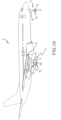
- an aircraft 10 includes landing gear, such as a left main landing gear 12, a right main landing gear 14, and nose landing gear 16.
- the left main landing gear 12, right main landing gear 14, and nose landing gear 16 typically support the aircraft 10 when the aircraft 10 is not flying, thereby allowing the aircraft 10 to taxi, take off, and land without damage.
- the left main landing gear 12 includes a first wheel 13A and a second wheel 13B coupled by an axle 20.
- the right main landing gear 14 includes a first wheel 15A and a second wheel 15B coupled by an axle 22.
- the nose landing gear 16 includes a first nose wheel 17A and a second nose wheel 17B coupled by an axle 24.
- the aircraft 10 comprises any number of landing gear(s), and each landing gear comprises any number of wheels.
- the left main landing gear 12, right main landing gear 14, and nose landing gear 16 are retracted when the aircraft 10 is in flight.
- one or more of the left main landing gear 12, right main landing gear 14, and nose landing gear 16 extends from an underside of a fuselage 28 of the aircraft 10, or from an underside of the wings 30 thereof.
- the aircraft 10 also includes a brake system that is applied to one or more of the wheels 13A, 13B, 15A, 15B, 17A, 17B of one or more of the respective left main landing gear 12, right main landing gear 14, and/or nose landing gear 16.
- brake systems of the aircraft 10 typically comprise a collection of assemblies, subsystems, and/or units that produce output signals for controlling the braking force and/or torque applied at one or more of the wheels 13A, 13B, 15A, 15B, 17A, 17B.
- Such brake systems typically communicate with the brakes of the left main landing gear 12, right main landing gear 14, and/or nose landing gear 16, and each brake is typically mounted to each wheel 13A, 13B, 15A, 15B, 17A, 17B in order to apply and release braking forces thereon.
- the brakes of the aircraft 10 further include a non-rotatable wheel support, the wheels 13A, 13B, 15A, 15B, 17A, 17B mounted to the wheel support for rotation, and a brake disk stack.
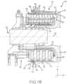
- a brake assembly 110 for mounting on an axle comprising a heat shield 200 is located on the aircraft 10 of FIG. 1A , in accordance with various embodiments.
- the brake assembly 110 for mounting on an axle typically comprises a bogie axle 112, a wheel 114 (e.g., the wheels 13A, 13B, 15A, 15B, 17A, 17B of FIG.
- a hub 116 and wheel well 118 including a hub 116 and wheel well 118, a web 120, a torque take-out assembly 122, one or more torque bars 124, a wheel rotational axis 126, a wheel well recess 128, an actuator 130, multiple brake rotors 32, multiple brake stators 34, a pressure plate 36, an end plate 38, a heat shield 200 which may have sections 142, multiple heat shield carriers 144, an air gap 146, multiple torque bar bolts 148, a torque bar pin 151, a wheel web hole 152, multiple heat shield fasteners 153, multiple rotor lugs 154, and multiple stator slots 156.
- Brake disks (e.g., the interleaved brake rotors 32 and brake stators 34) are disposed in the wheel well recess 128 of the wheel well 118.
- the brake rotors 32 and brake stators 34 may be referred to collectively as the brake stack or heat sink.
- the brake rotors 32 are typically secured to the torque bars 124 for rotating with the wheel 114, while the brake stators 34 are typically engaged with the torque take-out assembly 122.
- At least one actuator 130 is typically operable to compress the interleaved brake rotors 32 and brake stators 34 for stopping the aircraft 10 of FIG. 1A .
- the actuator 130 is shown as a hydraulically actuated piston, though pistons driven pneumatically and by electromechanical actuators are also contemplated herein.
- the pressure plate 36 and end plate 38 are disposed at opposite ends of the interleaved brake rotors 32 and brake stators 34.
- the torque take-out assembly 122 is typically secured to a stationary portion of a landing gear truck, such as a bogie beam or other landing gear strut, such that the torque take-out assembly 122 and brake stators 34 are prevented from rotating during braking of the aircraft 10 of FIG. 1A .
- the brake rotors 32 and brake stators 34 are typically fabricated from various materials, such as, for example carbon materials.
- the brake disks typically withstand and dissipate the heat generated from contact between the brake disks while braking the aircraft 10 of FIG. 1A .
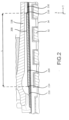
- heat shield 200 is attached to a wheel assembly, in accordance with various embodiments. As referred to herein, radially may refer to the x-direction, while axially may refer to the y-direction as shown in FIG. 1B and FIG. 2 .
- Heat shield 200 may be situated radially between the brake stack (brake rotors 32 and brake stators 34) and wheel well 118. Heat shield 200 may be configured to reduce an amount of radiative heat transferred from the brake stack to wheel well 118 during braking of the aircraft.
- Heat shield 200 may extend along an axial direction between the brake stack and wheel well 118.
- heat shield 200 may comprise a length, extending in an axial direction between the brake stack and wheel well 118.
- heat shield 200 may comprise a first structure portion 210, a second structure portion 220, and a third structure portion 230.
- First structure portion 210 may be similar in structure to third structure portion 230.
- First structure portion 210 second structure portion 220, and third structure portion 230 may each comprise a portion of the length of heat shield 200.
- heat shield 200 may begin as first structure portion 210, transition into second structure portion 220, and transition into third structure portion 230.
- a length of second structure portion 220 may be designated as L.
- L may extend an entire axial length of heat shield 200 such that a length of heat shield 200 and L are equal.
- heat shield 200 may be strategically positioned in an axial direction, in accordance with various embodiments.
- Second structure portion 220 comprising length L may be axially positioned along the y-axis such that it is positioned between the brake stack and wheel well 118 in areas that may be more likely to develop a tire fire.
- second structure portion 220 may be positioned such that it is radially inward and axially aligned with bead seat 119 of wheel well 118.
- Bead seat 119 may be more likely to cause a tire to ignite due to the close proximity of bead seat 119 to the tire, which may result in greater conductive heat transfer between bead seat 119 and the tire.
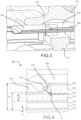
- a portion of heat shield 200 may comprise a first structure portion 210, a second structure portion 220, and a third structure portion 230.
- First structure portion 210 may transition to second structure portion 220 through first transition region 214 and second structure portion 220 may transition to third structure portion 230 through second transition region 216 (with momentary reference to FIG. 2 ).
- Second structure portion 220 may provide greater resistance to radiative heat transfer from the brake rotors 32 and brake stators 34 to wheel well 118.
- First structure portion 210 and third structure portion 230 may each comprise a first shield layer 240, an air gap layer 250 radially outward of first shield layer 240, a second shield layer 260 radially outward of air gap layer 250, a first insulation layer 270 radially outward of second shield layer 260, and a third shield layer 300 radially outward of first insulation layer 270.
- First shield layer 240 may define a cylindrical inner diameter surface of heat shield 200.
- first insulation layer 270 may be adjacent to second shield layer 260 and third shield layer 300.
- Second structure portion 220 may comprise the first shield layer 240, the air gap layer 250, the second shield layer 260, the first insulation layer 270 and the third shield layer 300. Second structure portion 220 may further comprise a foil layer 280 radially outward of first insulation layer 270, a second insulation layer 290 radially outward of foil layer 280 but radially inward of third shield layer 300. First shield layer 240, air gap layer 250, second shield layer 260, first insulation layer 270, foil layer 280, second insulation layer 290, and third shield layer 300 may be coaxial with each other. At first transition region 214, third shield layer 300 forms a first ramp extending between first structure portion 210 and second structure portion 220 of heat shield 200.
- Third shield layer 300 partially defines the first ramp, first structure portion 210, and second structure portion 220.
- the third shield layer extends from a radially outer surface of first insulation layer 270 to a radially outer surface of second insulation layer 290.
- third shield layer 300 may form a second ramp extending between second structure portion 220 and third structure portion 230 of heat shield 200.
- Third shield layer 300 may partially define the second ramp, second structure portion 220, and third structure portion 230.
- an air pocket 225 may be defined at a radially inner surface of third shield layer 300 between first insulation layer 270, foil layer 280, second insulation layer 290 and third shield layer 300. Air pocket 225 may allow cooling airflow through heat shield 200.
- a similar air pocket may be formed at second transition region 216 between first insulation layer 270, foil layer 280, second insulation layer 290, and third shield layer 300.
- First shield layer 240, second shield layer 260, and third shield layer 300 may comprise a steel alloy, in various embodiments, however, the shield layers are not limited in this regard. In various other embodiments, first shield layer 240, second shield layer 260, and third shield layer 300 may comprise other materials capable of maintaining structural integrity of heat shield 200 and shielding wheel well 118 from fires developing at or near the brake rotors 32 and brake stators 34. First shield layer 240, second shield layer 260, and third shield layer 300 may comprise thickness, denoted t1.
- t1 may be between approximately 0.005 inches (or 0.127 mm) and 0.025 inches (or 0.635 mm), between approximately 0.010 inches (or 0.254 mm) and 0.020 inches (or 0.508 mm), or between approximately 0.014 inches (or 0.356 mm) and 0.016 inches (or 0.406 mm). While in various embodiments t1 is equal in all first shield layer 240, second shield layer 260, and third shield layer 300, t1 is not limited in this regard. In various embodiments, first shield layer 240, second shield layer 260, and third shield layer 300 may comprise different thicknesses.
- First insulation layer 270 and second insulation layer 290 may comprise refractory ceramic fiber insulating papers such as those made by the company, Unifrax. First insulation layer 270 and second insulation layer 290 may also comprise insulating papers comprising alkaline earth silicates, and/or polycrystalline wool materials, however, first insulation layer 270 and second insulation layer 290 are not limited in this regard. First insulation layer 270 and second insulation layer 290 may comprise a thickness, denoted t2.
- t2 may be between approximately 0.060 inches (or 1.524 mm) and 0.080 inches (or 2.032 mm), between approximately 0.065 inches (or 1.651 mm) and 0.075 inches (or 1.905 mm), or between approximately 0.069 inches (or 1.753 mm) and 0.071 inches (1.803 mm), however, t2 is not limited in this regard.
- first insulation layer 270 and second insulation layer 290 are of equal thickness, in various embodiments, first insulation layer 270 may have a thickness greater or less than second insulation layer 290.
- Foil layer 280 may comprise a steel foil, titanium foil, or other metallic foil capable of preventing radiative heat transfer from the brake stack to wheel well 118.
- foil layer 280 may comprise a thickness, denoted t3.
- t3 may be between approximately 0.001 inches (or 0.025 mm) and 0.007 inches (or 0.178 mm), between approximately 0.002 inches (or 0.051 mm) and 0.006 inches (or 0.152 mm), or between 0.003 inches (or 0.076 mm) and 0.005 inches (or 0.127 mm), however, t3 is not limited in this regard.
- Foil layer 280 may function to prevent radiative heat transfer from the brake stack to wheel well 118 in the event flames breach first shield layer 240 and second shield layer 260 and first insulation layer 270 and second insulation layer 290 break apart.
- Heat shield 200 further comprises an air gap layer 250 situated radially between first shield layer 240 and second shield layer 260.
- Air gap layer 250 may function to minimize convective flow between first shield layer 240 and second shield layer 260.
- a flame may form radially inward of first shield layer 240.
- first shield layer 240 Prior to the flame burning through first shield layer 240, first shield layer 240 may increase in temperature.
- Air gap layer 250 may reduce the convective transfer of heat from first shield layer 240 to second shield layer 260 while first shield layer 240 is being heated by the flame. Accordingly, heat shield 200 may be more effective at reducing radiative heat transfer from the brake stack to wheel well 118 when compared with a heat shield comprising an additional layer of insulation in place of air gap layer 250. Additional layers of insulation in place of air gap layer 250 may function to keep first shield layer 240 at a higher temperature, thereby leading to a quicker burn through.
- First structure portion 210 and third structure portion 230 may comprise a thickness, denoted t4.
- t4 may be between approximately 0.100 inches (or 2.540 mm) and 0.200 inches (or 5.080 mm), between approximately 0.125 inches (or 3.175 mm) and 0.175 inches (or 4.445 mm), or between 0.152 inches (or 3.861 mm) and 0.154 inches (or 3.912 mm), however, t4 is not limited in this regard.
- t4 may comprise a greater or smaller thickness due to first shield layer 240, air gap layer 250, second shield layer 260, first insulation layer 270, and/or third shield layer 300 comprising a different thickness than disclosed in the present embodiment.
- Second structure portion 220 may comprise a different thickness, denoted t5.
- t5 may be between approximately 0.175 inches (or 4.445 mm) and 0.275 inches (or 6.985 mm), between approximately 0.200 inches (or 5.080 mm) and 0.230 inches (or 6.350 mm), or between approximately 0.227 inches (or 5.766 mm) and 0.229 inches (or 5.817 mm), however, t5 is not limited in this regard.
- t5 may comprise a greater or smaller thickness due to first shield layer 240, air gap layer 250, second shield layer 260, first insulation layer 270, foil layer 280, second insulation layer 290, and/or third shield layer 300 comprising a different thickness than disclosed in the present embodiment.
- the thickness t5 of second structure portion 220 may be thicker than the thickness t4 of first structure portion 210 in order to provide greater resistance to radiative heat transfer from the brake stack to wheel well 118. While various embodiments include a first structure portion 210, first transition region 214, second structure portion 220, second transition region 216, and third structure portion 230, the structure of heat shield 200 is not limited in this regard. In various embodiments, second structure portion 220 may extend an entire axial length of heat shield 200 to provide greater radiative heat transfer throughout an entire axial length of wheel well 118.
- Method 500 comprises forming a first shield layer defining a cylindrical inner diameter surface (Step 502).
- the method further comprises forming a second shield layer radially outward of the first shield layer such that an air gap layer is situated between the first shield layer and the second shield layer (Step 504).
- the method further comprises forming a first insulation layer radially outward of the second shield layer (Step 506).
- the method further comprises forming a foil layer radially outward of the first insulation layer (Step 508).
- the method further comprises further forming a second insulation layer radially outward of the first insulation layer (Step 510).
- the method further comprises forming a third shield layer radially outward of the second insulation layer (Step 512).
- references to "one embodiment”, “an embodiment”, “various embodiments”, etc. indicate that the embodiment described may include a particular feature, structure, or characteristic, but every embodiment may not necessarily include the particular feature, structure, or characteristic. Moreover, such phrases are not necessarily referring to the same embodiment. Further, when a particular feature, structure, or characteristic is described in connection with an embodiment, it is submitted that it is within the knowledge of one skilled in the art to affect such feature, structure, or characteristic in connection with other embodiments whether or not explicitly described. After reading the description, it will be apparent to one skilled in the relevant art(s) how to implement the invention in alternative embodiments.
Landscapes
- Engineering & Computer Science (AREA)
- General Engineering & Computer Science (AREA)
- Mechanical Engineering (AREA)
- Aviation & Aerospace Engineering (AREA)
- Braking Arrangements (AREA)
- Thermal Insulation (AREA)
Claims (14)
- Hitzeschild, umfassendeine erste Abschirmschicht (240), die eine zylindrische Innendurchmesserfläche des Hitzeschilds definiert, wobei die zylindrische Innendurchmesserfläche einen Radius und eine Achse aufweist;eine Luftspaltschicht (250) radial außerhalb der ersten Abschirmschicht;eine zweite Abschirmschicht (260) radial außerhalb der Luftspaltschicht; undeine erste Isolierschicht (270) radial außerhalb der zweiten Abschirmschicht; und gekennzeichnet durch:eine Folienschicht (280) radial außerhalb der ersten Isolierschicht;eine zweite Isolierschicht (290) radial außerhalb der Folienschicht; undeine dritte Abschirmschicht (300) radial außerhalb der zweiten Isolierschicht, wobei sich die dritte Abschirmschicht (300) von einer radial äußeren Fläche der ersten Isolierschicht (270) zu einer radial äußeren Fläche der zweiten Isolierschicht (290) erstreckt, und wobei die dritte Abschirmschicht eine erste Rampe (214) bildet, die sich von der radial äußeren Fläche der ersten Isolierschicht zu einer radial äußeren Fläche der zweiten Isolierschicht erstreckt, und wobei sich die erste Rampe in einer axialen Richtung von einem ersten Strukturabschnitt (210) des Hitzeschilds zu einem zweiten Strukturabschnitt (220) des Hitzeschilds erstreckt, und wobei die dritte Abschirmschicht teilweise den ersten Strukturabschnitt und den zweiten Strukturabschnitt definiert.
- Hitzeschild nach Anspruch 1, wobei die erste Abschirmschicht, die Luftspaltschicht, die zweite Abschirmschicht, die erste Isolierschicht, die Folienschicht, die zweite Isolierschicht und die dritte Abschirmschicht koaxial sind.
- Hitzeschild nach Anspruch 1 oder 2, ferner umfassend eine Lufttasche (225), die zwischen der ersten Isolierschicht, der Folienschicht, der zweiten Isolierschicht und der dritten Abschirmschicht definiert ist.
- Hitzeschild nach Anspruch 1, 2 oder 3, wobei die dritte Abschirmschicht eine zweite Rampe (216) bildet, die sich von der radial äußeren Fläche der zweiten Isolationsschicht zu der radial äußeren Fläche der ersten Isolierschicht erstreckt, wobei die zweite Rampe sich in axialer Richtung von dem zweiten Strukturabschnitt (220) des Hitzeschilds zu einem dritten Strukturabschnitt (230) des Hitzeschilds erstreckt, und wobei die dritte Abschirmschicht teilweise den dritten Strukturabschnitt definiert.
- Hitzeschild nach einem der vorhergehenden Ansprüche, wobei die erste Isolierschicht und die zweite Isolierschicht eine feuerfeste Keramikfaser, ein Erdalkalisilikat oder ein polykristallines Wollmaterial umfassen.
- Hitzeschild nach Anspruch 4, wobei die erste Isolierschicht in dem ersten Strukturabschnitt und dem dritten Strukturabschnitt zu der zweiten Abschirmschicht und der dritten Abschirmschicht benachbart ist.
- Hitzeschild nach einem der vorhergehenden Ansprüche, wobei sich die Folienschicht und die zweite Isolierschicht über weniger als eine axiale Gesamtlänge des Hitzeschilds erstrecken.
- Hitzeschild nach einem der vorhergehenden Ansprüche, wobei die erste Abschirmschicht, die zweite Abschirmschicht und die dritte Abschirmschicht jeweils eine Dicke zwischen ungefähr 0,127 mm (0,005 Zoll) und 0,635 mm (0,025 Zoll) umfassen.
- Bremsenbaugruppe für ein Flugzeug, umfassend:einen Bremssatz (32, 34);einen Radkasten (118); undeinen Hitzeschild (200) nach einem der vorhergehenden Ansprüche, der radial zwischen dem Bremssatz und dem Radkasten angeordnet ist.
- Bremsenbaugruppe nach Anspruch 9, wobei die dritte Abschirmschicht eine erste Rampe (214) bildet, die sich von der radial äußeren Fläche der ersten Isolierschicht zu der radial äußeren Fläche der zweiten Isolierschicht erstreckt, und wobei sich die erste Rampe in einer axialen Richtung von einem ersten Strukturabschnitt (210) des Hitzeschilds zu einem zweiten Strukturabschnitt (220) des Hitzeschilds erstreckt, und wobei der zweite Strukturabschnitt (220) des Hitzeschilds radial einwärts von und axial ausgerichtet an einem Wulstsitz (119) liegend von zwischen dem Bremssatz und dem Radkasten positioniert ist.
- Verfahren zum Herstellen eines Hitzeschilds, umfassendBilden einer ersten Abschirmschicht (240), die eine zylindrische Innendurchmesserfläche definiert;Bilden einer zweiten Abschirmschicht (260) radial außerhalb der ersten Abschirmschicht; undBilden einer ersten Isolierschicht (270) radial außerhalb der zweiten Abschirmschicht; und gekennzeichnet durch:Bilden einer Folienschicht (280) radial außerhalb der ersten Isolierschicht;Bilden einer zweiten Isolierschicht (290) radial außerhalb der Folienschicht; undBilden einer dritten Abschirmschicht (300) radial außerhalb der zweiten Isolierschicht und sich von einer radial äußeren Fläche der ersten Isolierschicht (270) zu einer radial äußeren Fläche der zweiten Isolierschicht (290) erstreckend, wobei die dritte Abschirmschicht eine erste Rampe (214) bildet, die sich von der radial äußeren Fläche der ersten Isolierschicht zu einer radial äußeren Fläche der zweiten Isolierschicht erstreckt, und wobei sich die erste Rampe in einer axialen Richtung von einem ersten Strukturabschnitt (210) des Hitzeschilds zu einem zweiten Strukturabschnitt (220) des Hitzeschilds erstreckt, und wobei die dritte Abschirmschicht teilweise den ersten Strukturabschnitt und den zweiten Strukturabschnitt definiert.
- Verfahren nach Anspruch 11, wobei das Bilden der zweiten Abschirmschicht Bilden der zweiten Abschirmschicht derart umfasst, dass eine Luftspaltschicht zwischen der zweiten Abschirmschicht und der ersten Abschirmschicht angeordnet ist.
- Verfahren nach Anspruch 11 oder 12, wobei die erste Hitzeschildschicht und die zweite Hitzeschildschicht koaxial mit der dritten Hitzeschildschicht gebildet werden.
- Verfahren nach Anspruch 11, 12 oder 13, wobei die Folienschicht und die zweite Isolierschicht so gebildet werden, dass sie sich über weniger als eine Gesamtlänge des Hitzeschilds erstrecken.
Applications Claiming Priority (1)
| Application Number | Priority Date | Filing Date | Title |
|---|---|---|---|
| US15/918,176 US10400839B1 (en) | 2018-03-12 | 2018-03-12 | Aircraft brake heat shield |
Publications (2)
| Publication Number | Publication Date |
|---|---|
| EP3539834A1 EP3539834A1 (de) | 2019-09-18 |
| EP3539834B1 true EP3539834B1 (de) | 2023-07-19 |
Family
ID=65801917
Family Applications (1)
| Application Number | Title | Priority Date | Filing Date |
|---|---|---|---|
| EP19162337.0A Active EP3539834B1 (de) | 2018-03-12 | 2019-03-12 | Hitzeschild für flugzeugbremse |
Country Status (2)
| Country | Link |
|---|---|
| US (1) | US10400839B1 (de) |
| EP (1) | EP3539834B1 (de) |
Families Citing this family (1)
| Publication number | Priority date | Publication date | Assignee | Title |
|---|---|---|---|---|
| FR3109765B1 (fr) * | 2020-05-04 | 2022-06-17 | Safran Landing Systems | Ecran thermique pour dispositif de freinage d’une roue d’aéronef |
Family Cites Families (19)
| Publication number | Priority date | Publication date | Assignee | Title |
|---|---|---|---|---|
| GB878973A (en) | 1959-06-22 | 1961-10-04 | Bendix Corp | A safety system for pneumatic-tired aircraft wheel and brake assemblies |
| US4017123A (en) | 1976-04-02 | 1977-04-12 | The Bendix Corporation | Dual layer heat shield for wheels |
| GB2172547B (en) * | 1985-03-19 | 1989-02-01 | Mitsubishi Metal Corp | Heat insulating material and heat-insulated conduit |
| US5002342A (en) * | 1989-12-28 | 1991-03-26 | Aircraft Braking Systems Corporation | Brake assembly heat shield |
| US5111577A (en) * | 1990-01-22 | 1992-05-12 | Atd Corporation | Pad including heat sink and thermal insulation areas |
| CH684206A5 (de) * | 1990-11-12 | 1994-07-29 | Matec Holding | Entsorgbarer Hitzeschild. |
| US5248013A (en) | 1992-02-13 | 1993-09-28 | The B. F. Goodrich Company | Heatshield installation for aircraft brake |
| GB9217795D0 (en) * | 1992-08-21 | 1992-10-07 | T & N Technology Ltd | Heat shields |
| US5424139A (en) * | 1994-01-10 | 1995-06-13 | Lydall, Inc. | Metal heat insulator |
| US5524406A (en) * | 1994-03-24 | 1996-06-11 | Atd Corporation | Insulating apparatus and method for attaching an insulating pad to a support |
| CA2297463C (en) * | 1997-06-09 | 2006-12-12 | Sevex North America, Inc. | Shaped multilayer metal foil shield structures and method of making |
| US20020098316A1 (en) * | 2001-01-25 | 2002-07-25 | Butler Richard M. | Multilayer foil insulation and method for manufacturing |
| US6797402B2 (en) * | 2001-09-28 | 2004-09-28 | Dana Corporation | Insulated heat shield with waved edge |
| EP1780057A3 (de) * | 2001-10-10 | 2007-05-16 | Goodrich Corporation | Bremsanordnung mit einem Hitzeschild in einem Flugzeugrad |
| DE10253832A1 (de) * | 2002-11-18 | 2004-05-27 | Carcoustics Tech Center Gmbh | Schallisolierender Hitzeschutzschild |
| US6966402B2 (en) * | 2003-06-02 | 2005-11-22 | Dana Corporation | Acoustical heat shield |
| US7585559B2 (en) * | 2003-06-03 | 2009-09-08 | Intellectual Property Holdings, Llc | Foam barrier heat shield |
| US8523108B2 (en) | 2011-03-24 | 2013-09-03 | Goodrich Corporation | Heat shield installation for aircraft wheel to improve convective cooling of aircraft brake |
| MX2015010931A (es) * | 2013-02-22 | 2016-07-19 | Interface Performance Materials Inc | Protector termica de peso ligero. |
-
2018
- 2018-03-12 US US15/918,176 patent/US10400839B1/en active Active
-
2019
- 2019-03-12 EP EP19162337.0A patent/EP3539834B1/de active Active
Also Published As
| Publication number | Publication date |
|---|---|
| EP3539834A1 (de) | 2019-09-18 |
| US10400839B1 (en) | 2019-09-03 |
| US20190277357A1 (en) | 2019-09-12 |
Similar Documents
| Publication | Publication Date | Title |
|---|---|---|
| EP3521161B1 (de) | Metallischer hitzeschild mit laminierte folie mit warzen | |
| EP3480072B1 (de) | Abschirmungsanbringungsvorrichtung | |
| EP3569400B1 (de) | Kohlenstoffnanoröhrchen-basierter hitzeschild | |
| JPS61248926A (ja) | 航空機などの車輪のための耐熱性デイスクブレ−キ | |
| EP3734104A1 (de) | Hydraulische bremszylinderkolbenverstellvorrichtung | |
| EP3726087B1 (de) | Mehrschichtiger kolbenisolator für hydraulischen bremszylinder | |
| EP3539834B1 (de) | Hitzeschild für flugzeugbremse | |
| EP4011724A1 (de) | Radanordnung mit rippen für drehmomentstütze | |
| EP3453612B1 (de) | Bremsmomentlastreaktion eines flugzeugs durch die fahrwerksdrehgestellstruktur | |
| EP3187746A1 (de) | Plattenanordnungen mit schwimmenden verschleissverkleidungen für mehrscheibenbremssystem und verfahren zur verringerung der vibrationen in einem mehrscheibenbremssystem | |
| EP3524517B1 (de) | Isolierte drehmomentplattenfussanordnung | |
| EP3051166B1 (de) | Reibscheiben mit schwimmenden verschleissauskleidungen | |
| EP3453614B1 (de) | Bremsmoment- und klemmkraftreaktion eines flugzeugs durch eine fahrwerksstruktur | |
| EP2126398B1 (de) | Bremsung | |
| US10309468B2 (en) | Torque plate barrel having blended barrel support pedestal | |
| EP4299942B1 (de) | Ausfallsicherer kolbendruckweg | |
| EP3925874B1 (de) | Abstandshalter eines flugzeugraddrehmomentstabs | |
| EP4261431B1 (de) | Geschlitzter drehmomentplattenzylinder | |
| EP4289689B1 (de) | Mehrschichtiger flugzeugbremsisolator | |
| EP4321768B1 (de) | Konischer drehmomentplattenzylinder zur verbesserung der dynamischen stabilität | |
| EP3978776B1 (de) | Kohlenstoffbremsstapelanordnung für verbesserte lebensdauer | |
| EP4420942A1 (de) | Bremsanlage mit elektrischen bremsaktuatoren und verfahren | |
| EP1650460B1 (de) | Aktuator für Flugzeugbremsen |
Legal Events
| Date | Code | Title | Description |
|---|---|---|---|
| PUAI | Public reference made under article 153(3) epc to a published international application that has entered the european phase |
Free format text: ORIGINAL CODE: 0009012 |
|
| STAA | Information on the status of an ep patent application or granted ep patent |
Free format text: STATUS: THE APPLICATION HAS BEEN PUBLISHED |
|
| AK | Designated contracting states |
Kind code of ref document: A1 Designated state(s): AL AT BE BG CH CY CZ DE DK EE ES FI FR GB GR HR HU IE IS IT LI LT LU LV MC MK MT NL NO PL PT RO RS SE SI SK SM TR |
|
| AX | Request for extension of the european patent |
Extension state: BA ME |
|
| STAA | Information on the status of an ep patent application or granted ep patent |
Free format text: STATUS: REQUEST FOR EXAMINATION WAS MADE |
|
| 17P | Request for examination filed |
Effective date: 20191120 |
|
| RBV | Designated contracting states (corrected) |
Designated state(s): AL AT BE BG CH CY CZ DE DK EE ES FI FR GB GR HR HU IE IS IT LI LT LU LV MC MK MT NL NO PL PT RO RS SE SI SK SM TR |
|
| STAA | Information on the status of an ep patent application or granted ep patent |
Free format text: STATUS: EXAMINATION IS IN PROGRESS |
|
| 17Q | First examination report despatched |
Effective date: 20210416 |
|
| GRAP | Despatch of communication of intention to grant a patent |
Free format text: ORIGINAL CODE: EPIDOSNIGR1 |
|
| STAA | Information on the status of an ep patent application or granted ep patent |
Free format text: STATUS: GRANT OF PATENT IS INTENDED |
|
| INTG | Intention to grant announced |
Effective date: 20230206 |
|
| RIN1 | Information on inventor provided before grant (corrected) |
Inventor name: SCHROEDER, DOUG Inventor name: MAY, WILLIAM P. Inventor name: LEIVA, ORLY |
|
| GRAS | Grant fee paid |
Free format text: ORIGINAL CODE: EPIDOSNIGR3 |
|
| GRAA | (expected) grant |
Free format text: ORIGINAL CODE: 0009210 |
|
| STAA | Information on the status of an ep patent application or granted ep patent |
Free format text: STATUS: THE PATENT HAS BEEN GRANTED |
|
| AK | Designated contracting states |
Kind code of ref document: B1 Designated state(s): AL AT BE BG CH CY CZ DE DK EE ES FI FR GB GR HR HU IE IS IT LI LT LU LV MC MK MT NL NO PL PT RO RS SE SI SK SM TR |
|
| REG | Reference to a national code |
Ref country code: GB Ref legal event code: FG4D |
|
| REG | Reference to a national code |
Ref country code: CH Ref legal event code: EP |
|
| REG | Reference to a national code |
Ref country code: DE Ref legal event code: R096 Ref document number: 602019032854 Country of ref document: DE |
|
| REG | Reference to a national code |
Ref country code: IE Ref legal event code: FG4D |
|
| P01 | Opt-out of the competence of the unified patent court (upc) registered |
Effective date: 20230922 |
|
| REG | Reference to a national code |
Ref country code: LT Ref legal event code: MG9D |
|
| REG | Reference to a national code |
Ref country code: NL Ref legal event code: MP Effective date: 20230719 |
|
| REG | Reference to a national code |
Ref country code: AT Ref legal event code: MK05 Ref document number: 1589169 Country of ref document: AT Kind code of ref document: T Effective date: 20230719 |
|
| PG25 | Lapsed in a contracting state [announced via postgrant information from national office to epo] |
Ref country code: NL Free format text: LAPSE BECAUSE OF FAILURE TO SUBMIT A TRANSLATION OF THE DESCRIPTION OR TO PAY THE FEE WITHIN THE PRESCRIBED TIME-LIMIT Effective date: 20230719 |
|
| PG25 | Lapsed in a contracting state [announced via postgrant information from national office to epo] |
Ref country code: GR Free format text: LAPSE BECAUSE OF FAILURE TO SUBMIT A TRANSLATION OF THE DESCRIPTION OR TO PAY THE FEE WITHIN THE PRESCRIBED TIME-LIMIT Effective date: 20231020 |
|
| PG25 | Lapsed in a contracting state [announced via postgrant information from national office to epo] |
Ref country code: IS Free format text: LAPSE BECAUSE OF FAILURE TO SUBMIT A TRANSLATION OF THE DESCRIPTION OR TO PAY THE FEE WITHIN THE PRESCRIBED TIME-LIMIT Effective date: 20231119 |
|
| PG25 | Lapsed in a contracting state [announced via postgrant information from national office to epo] |
Ref country code: SE Free format text: LAPSE BECAUSE OF FAILURE TO SUBMIT A TRANSLATION OF THE DESCRIPTION OR TO PAY THE FEE WITHIN THE PRESCRIBED TIME-LIMIT Effective date: 20230719 Ref country code: RS Free format text: LAPSE BECAUSE OF FAILURE TO SUBMIT A TRANSLATION OF THE DESCRIPTION OR TO PAY THE FEE WITHIN THE PRESCRIBED TIME-LIMIT Effective date: 20230719 Ref country code: PT Free format text: LAPSE BECAUSE OF FAILURE TO SUBMIT A TRANSLATION OF THE DESCRIPTION OR TO PAY THE FEE WITHIN THE PRESCRIBED TIME-LIMIT Effective date: 20231120 Ref country code: NO Free format text: LAPSE BECAUSE OF FAILURE TO SUBMIT A TRANSLATION OF THE DESCRIPTION OR TO PAY THE FEE WITHIN THE PRESCRIBED TIME-LIMIT Effective date: 20231019 Ref country code: LV Free format text: LAPSE BECAUSE OF FAILURE TO SUBMIT A TRANSLATION OF THE DESCRIPTION OR TO PAY THE FEE WITHIN THE PRESCRIBED TIME-LIMIT Effective date: 20230719 Ref country code: LT Free format text: LAPSE BECAUSE OF FAILURE TO SUBMIT A TRANSLATION OF THE DESCRIPTION OR TO PAY THE FEE WITHIN THE PRESCRIBED TIME-LIMIT Effective date: 20230719 Ref country code: IS Free format text: LAPSE BECAUSE OF FAILURE TO SUBMIT A TRANSLATION OF THE DESCRIPTION OR TO PAY THE FEE WITHIN THE PRESCRIBED TIME-LIMIT Effective date: 20231119 Ref country code: HR Free format text: LAPSE BECAUSE OF FAILURE TO SUBMIT A TRANSLATION OF THE DESCRIPTION OR TO PAY THE FEE WITHIN THE PRESCRIBED TIME-LIMIT Effective date: 20230719 Ref country code: GR Free format text: LAPSE BECAUSE OF FAILURE TO SUBMIT A TRANSLATION OF THE DESCRIPTION OR TO PAY THE FEE WITHIN THE PRESCRIBED TIME-LIMIT Effective date: 20231020 Ref country code: FI Free format text: LAPSE BECAUSE OF FAILURE TO SUBMIT A TRANSLATION OF THE DESCRIPTION OR TO PAY THE FEE WITHIN THE PRESCRIBED TIME-LIMIT Effective date: 20230719 Ref country code: AT Free format text: LAPSE BECAUSE OF FAILURE TO SUBMIT A TRANSLATION OF THE DESCRIPTION OR TO PAY THE FEE WITHIN THE PRESCRIBED TIME-LIMIT Effective date: 20230719 |
|
| PG25 | Lapsed in a contracting state [announced via postgrant information from national office to epo] |
Ref country code: PL Free format text: LAPSE BECAUSE OF FAILURE TO SUBMIT A TRANSLATION OF THE DESCRIPTION OR TO PAY THE FEE WITHIN THE PRESCRIBED TIME-LIMIT Effective date: 20230719 |
|
| REG | Reference to a national code |
Ref country code: DE Ref legal event code: R097 Ref document number: 602019032854 Country of ref document: DE |
|
| PG25 | Lapsed in a contracting state [announced via postgrant information from national office to epo] |
Ref country code: ES Free format text: LAPSE BECAUSE OF FAILURE TO SUBMIT A TRANSLATION OF THE DESCRIPTION OR TO PAY THE FEE WITHIN THE PRESCRIBED TIME-LIMIT Effective date: 20230719 |
|
| PG25 | Lapsed in a contracting state [announced via postgrant information from national office to epo] |
Ref country code: SM Free format text: LAPSE BECAUSE OF FAILURE TO SUBMIT A TRANSLATION OF THE DESCRIPTION OR TO PAY THE FEE WITHIN THE PRESCRIBED TIME-LIMIT Effective date: 20230719 Ref country code: RO Free format text: LAPSE BECAUSE OF FAILURE TO SUBMIT A TRANSLATION OF THE DESCRIPTION OR TO PAY THE FEE WITHIN THE PRESCRIBED TIME-LIMIT Effective date: 20230719 Ref country code: ES Free format text: LAPSE BECAUSE OF FAILURE TO SUBMIT A TRANSLATION OF THE DESCRIPTION OR TO PAY THE FEE WITHIN THE PRESCRIBED TIME-LIMIT Effective date: 20230719 Ref country code: EE Free format text: LAPSE BECAUSE OF FAILURE TO SUBMIT A TRANSLATION OF THE DESCRIPTION OR TO PAY THE FEE WITHIN THE PRESCRIBED TIME-LIMIT Effective date: 20230719 Ref country code: DK Free format text: LAPSE BECAUSE OF FAILURE TO SUBMIT A TRANSLATION OF THE DESCRIPTION OR TO PAY THE FEE WITHIN THE PRESCRIBED TIME-LIMIT Effective date: 20230719 Ref country code: CZ Free format text: LAPSE BECAUSE OF FAILURE TO SUBMIT A TRANSLATION OF THE DESCRIPTION OR TO PAY THE FEE WITHIN THE PRESCRIBED TIME-LIMIT Effective date: 20230719 Ref country code: SK Free format text: LAPSE BECAUSE OF FAILURE TO SUBMIT A TRANSLATION OF THE DESCRIPTION OR TO PAY THE FEE WITHIN THE PRESCRIBED TIME-LIMIT Effective date: 20230719 |
|
| PLBE | No opposition filed within time limit |
Free format text: ORIGINAL CODE: 0009261 |
|
| STAA | Information on the status of an ep patent application or granted ep patent |
Free format text: STATUS: NO OPPOSITION FILED WITHIN TIME LIMIT |
|
| PG25 | Lapsed in a contracting state [announced via postgrant information from national office to epo] |
Ref country code: IT Free format text: LAPSE BECAUSE OF FAILURE TO SUBMIT A TRANSLATION OF THE DESCRIPTION OR TO PAY THE FEE WITHIN THE PRESCRIBED TIME-LIMIT Effective date: 20230719 |
|
| 26N | No opposition filed |
Effective date: 20240422 |
|
| PG25 | Lapsed in a contracting state [announced via postgrant information from national office to epo] |
Ref country code: SI Free format text: LAPSE BECAUSE OF FAILURE TO SUBMIT A TRANSLATION OF THE DESCRIPTION OR TO PAY THE FEE WITHIN THE PRESCRIBED TIME-LIMIT Effective date: 20230719 |
|
| REG | Reference to a national code |
Ref country code: DE Ref legal event code: R119 Ref document number: 602019032854 Country of ref document: DE |
|
| REG | Reference to a national code |
Ref country code: CH Ref legal event code: PL |
|
| PG25 | Lapsed in a contracting state [announced via postgrant information from national office to epo] |
Ref country code: BG Free format text: LAPSE BECAUSE OF FAILURE TO SUBMIT A TRANSLATION OF THE DESCRIPTION OR TO PAY THE FEE WITHIN THE PRESCRIBED TIME-LIMIT Effective date: 20230719 |
|
| PG25 | Lapsed in a contracting state [announced via postgrant information from national office to epo] |
Ref country code: LU Free format text: LAPSE BECAUSE OF NON-PAYMENT OF DUE FEES Effective date: 20240312 |
|
| PG25 | Lapsed in a contracting state [announced via postgrant information from national office to epo] |
Ref country code: MC Free format text: LAPSE BECAUSE OF FAILURE TO SUBMIT A TRANSLATION OF THE DESCRIPTION OR TO PAY THE FEE WITHIN THE PRESCRIBED TIME-LIMIT Effective date: 20230719 |
|
| PG25 | Lapsed in a contracting state [announced via postgrant information from national office to epo] |
Ref country code: MC Free format text: LAPSE BECAUSE OF FAILURE TO SUBMIT A TRANSLATION OF THE DESCRIPTION OR TO PAY THE FEE WITHIN THE PRESCRIBED TIME-LIMIT Effective date: 20230719 Ref country code: LU Free format text: LAPSE BECAUSE OF NON-PAYMENT OF DUE FEES Effective date: 20240312 Ref country code: BG Free format text: LAPSE BECAUSE OF FAILURE TO SUBMIT A TRANSLATION OF THE DESCRIPTION OR TO PAY THE FEE WITHIN THE PRESCRIBED TIME-LIMIT Effective date: 20230719 |
|
| REG | Reference to a national code |
Ref country code: BE Ref legal event code: MM Effective date: 20240331 |
|
| PG25 | Lapsed in a contracting state [announced via postgrant information from national office to epo] |
Ref country code: DE Free format text: LAPSE BECAUSE OF NON-PAYMENT OF DUE FEES Effective date: 20241001 |
|
| PG25 | Lapsed in a contracting state [announced via postgrant information from national office to epo] |
Ref country code: BE Free format text: LAPSE BECAUSE OF NON-PAYMENT OF DUE FEES Effective date: 20240331 |
|
| PG25 | Lapsed in a contracting state [announced via postgrant information from national office to epo] |
Ref country code: IE Free format text: LAPSE BECAUSE OF NON-PAYMENT OF DUE FEES Effective date: 20240312 |
|
| PG25 | Lapsed in a contracting state [announced via postgrant information from national office to epo] |
Ref country code: IE Free format text: LAPSE BECAUSE OF NON-PAYMENT OF DUE FEES Effective date: 20240312 Ref country code: DE Free format text: LAPSE BECAUSE OF NON-PAYMENT OF DUE FEES Effective date: 20241001 Ref country code: BE Free format text: LAPSE BECAUSE OF NON-PAYMENT OF DUE FEES Effective date: 20240331 Ref country code: CH Free format text: LAPSE BECAUSE OF NON-PAYMENT OF DUE FEES Effective date: 20240331 |
|
| PG25 | Lapsed in a contracting state [announced via postgrant information from national office to epo] |
Ref country code: CY Free format text: LAPSE BECAUSE OF FAILURE TO SUBMIT A TRANSLATION OF THE DESCRIPTION OR TO PAY THE FEE WITHIN THE PRESCRIBED TIME-LIMIT; INVALID AB INITIO Effective date: 20190312 |
|
| PG25 | Lapsed in a contracting state [announced via postgrant information from national office to epo] |
Ref country code: HU Free format text: LAPSE BECAUSE OF FAILURE TO SUBMIT A TRANSLATION OF THE DESCRIPTION OR TO PAY THE FEE WITHIN THE PRESCRIBED TIME-LIMIT; INVALID AB INITIO Effective date: 20190312 |
|
| PG25 | Lapsed in a contracting state [announced via postgrant information from national office to epo] |
Ref country code: TR Free format text: LAPSE BECAUSE OF FAILURE TO SUBMIT A TRANSLATION OF THE DESCRIPTION OR TO PAY THE FEE WITHIN THE PRESCRIBED TIME-LIMIT Effective date: 20230719 |
|
| PGFP | Annual fee paid to national office [announced via postgrant information from national office to epo] |
Ref country code: GB Payment date: 20260219 Year of fee payment: 8 |
|
| PGFP | Annual fee paid to national office [announced via postgrant information from national office to epo] |
Ref country code: FR Payment date: 20260219 Year of fee payment: 8 |