EP3539834B1 - Aircraft brake heat shield - Google Patents
Aircraft brake heat shield Download PDFInfo
- Publication number
- EP3539834B1 EP3539834B1 EP19162337.0A EP19162337A EP3539834B1 EP 3539834 B1 EP3539834 B1 EP 3539834B1 EP 19162337 A EP19162337 A EP 19162337A EP 3539834 B1 EP3539834 B1 EP 3539834B1
- Authority
- EP
- European Patent Office
- Prior art keywords
- layer
- shield
- insulation layer
- heat shield
- structure portion
- Prior art date
- Legal status (The legal status is an assumption and is not a legal conclusion. Google has not performed a legal analysis and makes no representation as to the accuracy of the status listed.)
- Active
Links
- 238000009413 insulation Methods 0.000 claims description 89
- 239000011888 foil Substances 0.000 claims description 28
- 238000000034 method Methods 0.000 claims description 16
- 239000000463 material Substances 0.000 claims description 8
- 230000004323 axial length Effects 0.000 claims description 5
- 239000011324 bead Substances 0.000 claims description 5
- 239000000835 fiber Substances 0.000 claims description 5
- 239000011214 refractory ceramic Substances 0.000 claims description 5
- 210000002268 wool Anatomy 0.000 claims description 5
- BPQQTUXANYXVAA-UHFFFAOYSA-N Orthosilicate Chemical compound [O-][Si]([O-])([O-])[O-] BPQQTUXANYXVAA-UHFFFAOYSA-N 0.000 claims description 4
- 238000004519 manufacturing process Methods 0.000 claims description 4
- 230000007704 transition Effects 0.000 description 12
- 230000008901 benefit Effects 0.000 description 6
- 229910000851 Alloy steel Inorganic materials 0.000 description 1
- 229910000831 Steel Inorganic materials 0.000 description 1
- RTAQQCXQSZGOHL-UHFFFAOYSA-N Titanium Chemical compound [Ti] RTAQQCXQSZGOHL-UHFFFAOYSA-N 0.000 description 1
- 230000000712 assembly Effects 0.000 description 1
- 238000000429 assembly Methods 0.000 description 1
- 239000003575 carbonaceous material Substances 0.000 description 1
- 239000000969 carrier Substances 0.000 description 1
- 230000006835 compression Effects 0.000 description 1
- 238000007906 compression Methods 0.000 description 1
- 238000001816 cooling Methods 0.000 description 1
- 230000008878 coupling Effects 0.000 description 1
- 238000010168 coupling process Methods 0.000 description 1
- 238000005859 coupling reaction Methods 0.000 description 1
- 238000010586 diagram Methods 0.000 description 1
- 150000004760 silicates Chemical class 0.000 description 1
- 239000010959 steel Substances 0.000 description 1
- 239000000126 substance Substances 0.000 description 1
- 230000002459 sustained effect Effects 0.000 description 1
Images

Classifications
-
- F—MECHANICAL ENGINEERING; LIGHTING; HEATING; WEAPONS; BLASTING
- F16—ENGINEERING ELEMENTS AND UNITS; GENERAL MEASURES FOR PRODUCING AND MAINTAINING EFFECTIVE FUNCTIONING OF MACHINES OR INSTALLATIONS; THERMAL INSULATION IN GENERAL
- F16D—COUPLINGS FOR TRANSMITTING ROTATION; CLUTCHES; BRAKES
- F16D55/00—Brakes with substantially-radial braking surfaces pressed together in axial direction, e.g. disc brakes
- F16D55/24—Brakes with substantially-radial braking surfaces pressed together in axial direction, e.g. disc brakes with a plurality of axially-movable discs, lamellae, or pads, pressed from one side towards an axially-located member
- F16D55/26—Brakes with substantially-radial braking surfaces pressed together in axial direction, e.g. disc brakes with a plurality of axially-movable discs, lamellae, or pads, pressed from one side towards an axially-located member without self-tightening action
- F16D55/36—Brakes with a plurality of rotating discs all lying side by side
-
- F—MECHANICAL ENGINEERING; LIGHTING; HEATING; WEAPONS; BLASTING
- F16—ENGINEERING ELEMENTS AND UNITS; GENERAL MEASURES FOR PRODUCING AND MAINTAINING EFFECTIVE FUNCTIONING OF MACHINES OR INSTALLATIONS; THERMAL INSULATION IN GENERAL
- F16D—COUPLINGS FOR TRANSMITTING ROTATION; CLUTCHES; BRAKES
- F16D65/00—Parts or details
- F16D65/78—Features relating to cooling
- F16D65/84—Features relating to cooling for disc brakes
-
- B—PERFORMING OPERATIONS; TRANSPORTING
- B32—LAYERED PRODUCTS
- B32B—LAYERED PRODUCTS, i.e. PRODUCTS BUILT-UP OF STRATA OF FLAT OR NON-FLAT, e.g. CELLULAR OR HONEYCOMB, FORM
- B32B15/00—Layered products comprising a layer of metal
- B32B15/04—Layered products comprising a layer of metal comprising metal as the main or only constituent of a layer, which is next to another layer of the same or of a different material
-
- B—PERFORMING OPERATIONS; TRANSPORTING
- B32—LAYERED PRODUCTS
- B32B—LAYERED PRODUCTS, i.e. PRODUCTS BUILT-UP OF STRATA OF FLAT OR NON-FLAT, e.g. CELLULAR OR HONEYCOMB, FORM
- B32B15/00—Layered products comprising a layer of metal
- B32B15/18—Layered products comprising a layer of metal comprising iron or steel
-
- B—PERFORMING OPERATIONS; TRANSPORTING
- B64—AIRCRAFT; AVIATION; COSMONAUTICS
- B64C—AEROPLANES; HELICOPTERS
- B64C25/00—Alighting gear
- B64C25/32—Alighting gear characterised by elements which contact the ground or similar surface
- B64C25/42—Arrangement or adaptation of brakes
-
- F—MECHANICAL ENGINEERING; LIGHTING; HEATING; WEAPONS; BLASTING
- F16—ENGINEERING ELEMENTS AND UNITS; GENERAL MEASURES FOR PRODUCING AND MAINTAINING EFFECTIVE FUNCTIONING OF MACHINES OR INSTALLATIONS; THERMAL INSULATION IN GENERAL
- F16D—COUPLINGS FOR TRANSMITTING ROTATION; CLUTCHES; BRAKES
- F16D65/00—Parts or details
- F16D65/14—Actuating mechanisms for brakes; Means for initiating operation at a predetermined position
- F16D65/16—Actuating mechanisms for brakes; Means for initiating operation at a predetermined position arranged in or on the brake
- F16D65/18—Actuating mechanisms for brakes; Means for initiating operation at a predetermined position arranged in or on the brake adapted for drawing members together, e.g. for disc brakes
- F16D65/186—Actuating mechanisms for brakes; Means for initiating operation at a predetermined position arranged in or on the brake adapted for drawing members together, e.g. for disc brakes with full-face force-applying member, e.g. annular
-
- F—MECHANICAL ENGINEERING; LIGHTING; HEATING; WEAPONS; BLASTING
- F16—ENGINEERING ELEMENTS AND UNITS; GENERAL MEASURES FOR PRODUCING AND MAINTAINING EFFECTIVE FUNCTIONING OF MACHINES OR INSTALLATIONS; THERMAL INSULATION IN GENERAL
- F16D—COUPLINGS FOR TRANSMITTING ROTATION; CLUTCHES; BRAKES
- F16D65/00—Parts or details
- F16D65/78—Features relating to cooling
- F16D65/84—Features relating to cooling for disc brakes
- F16D65/847—Features relating to cooling for disc brakes with open cooling system, e.g. cooled by air
-
- B—PERFORMING OPERATIONS; TRANSPORTING
- B32—LAYERED PRODUCTS
- B32B—LAYERED PRODUCTS, i.e. PRODUCTS BUILT-UP OF STRATA OF FLAT OR NON-FLAT, e.g. CELLULAR OR HONEYCOMB, FORM
- B32B2250/00—Layers arrangement
- B32B2250/05—5 or more layers
-
- B—PERFORMING OPERATIONS; TRANSPORTING
- B32—LAYERED PRODUCTS
- B32B—LAYERED PRODUCTS, i.e. PRODUCTS BUILT-UP OF STRATA OF FLAT OR NON-FLAT, e.g. CELLULAR OR HONEYCOMB, FORM
- B32B2262/00—Composition or structural features of fibres which form a fibrous or filamentary layer or are present as additives
- B32B2262/10—Inorganic fibres
- B32B2262/105—Ceramic fibres
-
- B—PERFORMING OPERATIONS; TRANSPORTING
- B32—LAYERED PRODUCTS
- B32B—LAYERED PRODUCTS, i.e. PRODUCTS BUILT-UP OF STRATA OF FLAT OR NON-FLAT, e.g. CELLULAR OR HONEYCOMB, FORM
- B32B2307/00—Properties of the layers or laminate
- B32B2307/30—Properties of the layers or laminate having particular thermal properties
- B32B2307/306—Resistant to heat
-
- B—PERFORMING OPERATIONS; TRANSPORTING
- B32—LAYERED PRODUCTS
- B32B—LAYERED PRODUCTS, i.e. PRODUCTS BUILT-UP OF STRATA OF FLAT OR NON-FLAT, e.g. CELLULAR OR HONEYCOMB, FORM
- B32B2605/00—Vehicles
- B32B2605/18—Aircraft
-
- F—MECHANICAL ENGINEERING; LIGHTING; HEATING; WEAPONS; BLASTING
- F16—ENGINEERING ELEMENTS AND UNITS; GENERAL MEASURES FOR PRODUCING AND MAINTAINING EFFECTIVE FUNCTIONING OF MACHINES OR INSTALLATIONS; THERMAL INSULATION IN GENERAL
- F16D—COUPLINGS FOR TRANSMITTING ROTATION; CLUTCHES; BRAKES
- F16D55/00—Brakes with substantially-radial braking surfaces pressed together in axial direction, e.g. disc brakes
- F16D2055/0004—Parts or details of disc brakes
- F16D2055/0058—Fully lined, i.e. braking surface extending over the entire disc circumference
-
- F—MECHANICAL ENGINEERING; LIGHTING; HEATING; WEAPONS; BLASTING
- F16—ENGINEERING ELEMENTS AND UNITS; GENERAL MEASURES FOR PRODUCING AND MAINTAINING EFFECTIVE FUNCTIONING OF MACHINES OR INSTALLATIONS; THERMAL INSULATION IN GENERAL
- F16D—COUPLINGS FOR TRANSMITTING ROTATION; CLUTCHES; BRAKES
- F16D65/00—Parts or details
- F16D65/78—Features relating to cooling
- F16D2065/785—Heat insulation or reflection
-
- F—MECHANICAL ENGINEERING; LIGHTING; HEATING; WEAPONS; BLASTING
- F16—ENGINEERING ELEMENTS AND UNITS; GENERAL MEASURES FOR PRODUCING AND MAINTAINING EFFECTIVE FUNCTIONING OF MACHINES OR INSTALLATIONS; THERMAL INSULATION IN GENERAL
- F16D—COUPLINGS FOR TRANSMITTING ROTATION; CLUTCHES; BRAKES
- F16D2200/00—Materials; Production methods therefor
- F16D2200/0034—Materials; Production methods therefor non-metallic
- F16D2200/0039—Ceramics
-
- F—MECHANICAL ENGINEERING; LIGHTING; HEATING; WEAPONS; BLASTING
- F16—ENGINEERING ELEMENTS AND UNITS; GENERAL MEASURES FOR PRODUCING AND MAINTAINING EFFECTIVE FUNCTIONING OF MACHINES OR INSTALLATIONS; THERMAL INSULATION IN GENERAL
- F16D—COUPLINGS FOR TRANSMITTING ROTATION; CLUTCHES; BRAKES
- F16D2200/00—Materials; Production methods therefor
- F16D2200/006—Materials; Production methods therefor containing fibres or particles
- F16D2200/0065—Inorganic, e.g. non-asbestos mineral fibres
-
- F—MECHANICAL ENGINEERING; LIGHTING; HEATING; WEAPONS; BLASTING
- F16—ENGINEERING ELEMENTS AND UNITS; GENERAL MEASURES FOR PRODUCING AND MAINTAINING EFFECTIVE FUNCTIONING OF MACHINES OR INSTALLATIONS; THERMAL INSULATION IN GENERAL
- F16D—COUPLINGS FOR TRANSMITTING ROTATION; CLUTCHES; BRAKES
- F16D2200/00—Materials; Production methods therefor
- F16D2200/0078—Materials; Production methods therefor laminated
-
- F—MECHANICAL ENGINEERING; LIGHTING; HEATING; WEAPONS; BLASTING
- F16—ENGINEERING ELEMENTS AND UNITS; GENERAL MEASURES FOR PRODUCING AND MAINTAINING EFFECTIVE FUNCTIONING OF MACHINES OR INSTALLATIONS; THERMAL INSULATION IN GENERAL
- F16D—COUPLINGS FOR TRANSMITTING ROTATION; CLUTCHES; BRAKES
- F16D55/00—Brakes with substantially-radial braking surfaces pressed together in axial direction, e.g. disc brakes
- F16D55/24—Brakes with substantially-radial braking surfaces pressed together in axial direction, e.g. disc brakes with a plurality of axially-movable discs, lamellae, or pads, pressed from one side towards an axially-located member
Definitions
- the present invention relates to heat shield systems and methods, and more particularly, to heat shield systems and methods for aircraft braking systems.
- Aircraft should complete a successful Rejected Takeoff (RTO) without allowing a sustained tire fire for a time period thereafter.
- heat shields may be used to tend to prevent such a fire.
- Heat shields are known from US 5,002,342 , EP 1780057 , US 2006/124387 and GB 2172547 .
- a heat shield is provided as defined by claim 1.
- the first shield layer, the air gap layer, the second shield layer, the first insulation layer, the foil layer, the second insulation layer, and the third shield layer may be coaxial.
- An air pocket may be defined between the first insulation layer, the foil layer, the second insulation layer, and the third shield layer.
- the first insulation layer and second insulation layer may comprise one of a refractory ceramic fiber, an alkaline earth silicate, or a polycrystalline wool material.
- the first insulation layer may be adjacent to the second shield layer and the third shield layer in the first structure portion and the second structure portion.
- the foil layer and second insulation layer may extend less than an overall axial length of the heat shield.
- the first shield layer, second shield layer, and third shield layer may each comprise a thickness between approximately 0.127 mm (0.005 inches) and 0.635 mm (0.025 inches).
- a brake assembly for an aircraft may comprise a brake stack, a wheel well, and a heat shield comprising a first shield layer defining a cylindrical inner diameter surface of the heat shield, the cylindrical inner diameter surface having a radius and an axis, an air gap layer radially outward of the first shield layer, a second shield layer radially outward of the air gap layer, a first insulation layer radially outward of the second shield layer, a foil layer radially outward of the second shield layer, a second insulation layer radially outward of the foil layer, and a third shield layer radially outward of the second insulation layer.
- the heat shield may be situated radially between the brake stack and the wheel well.
- the first shield layer, the air gap layer, the second shield layer, the first insulation layer, the foil layer, the second insulation layer, and the third shield layer may be coaxial with each other.
- the brake assembly may further comprise an air pocket defined between the first insulation layer, the foil layer, the second insulation layer, and the third shield layer.
- the brake assembly may further comprise a first ramp extending from a radially outer surface of the first insulation layer to a radially outer surface of the second insulation layer and extending in an axial direction from a first structure portion to a second structure portion of the heat shield, wherein the third shield layer partially defines the first ramp, first structure portion, and second structure portion.
- the first insulation layer and second insulation layer may comprise one of a refractory ceramic fiber, an alkaline earth silicate, or a polycrystalline wool material.
- a method of manufacturing a heat shield is provided as defined by claim 11.
- forming the second shield layer may comprise forming the second shield layer such that an air gap layer is situated between the second shield layer and the first shield layer.
- the heat shield layers may be formed coaxial with each other.
- the foil layer and second insulation layer may be formed to extend less than an overall length of the heat shield.
- the first insulation layer and second insulation layer may be formed from one of a refractory ceramic fiber, an alkaline earth silicate, or a polycrystalline wool material.
- any of the method or process descriptions may be executed in any order and are not necessarily limited to the order presented.
- any reference to singular includes plural embodiments, and any reference to more than one component or step may include a singular embodiment or step.
- any reference to attached, fixed, connected, or the like may include permanent, removable, temporary, partial, full, and/or any other possible attachment option.
- any reference to without contact (or similar phrases) may also include reduced contact or minimal contact.
- Various embodiments of the present invention may result in improved heat shielding between a brake stack and an aircraft tire during RTOs.
- the aircraft is traveling at a high rate of speed and aircraft brakes are activated in order to reduce the speed of the aircraft.
- the aircraft brakes convert kinetic energy to thermal energy through friction, leading to high temperatures in the brake stacks.
- the heat in a brake stack may be transferred to an aircraft tire, which increases the potential for the tire to ignite. Accordingly, heat shields may be desired to reduce heat transfer from a brake stack to a tire.
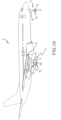
- an aircraft 10 includes landing gear, such as a left main landing gear 12, a right main landing gear 14, and nose landing gear 16.
- the left main landing gear 12, right main landing gear 14, and nose landing gear 16 typically support the aircraft 10 when the aircraft 10 is not flying, thereby allowing the aircraft 10 to taxi, take off, and land without damage.
- the left main landing gear 12 includes a first wheel 13A and a second wheel 13B coupled by an axle 20.
- the right main landing gear 14 includes a first wheel 15A and a second wheel 15B coupled by an axle 22.
- the nose landing gear 16 includes a first nose wheel 17A and a second nose wheel 17B coupled by an axle 24.
- the aircraft 10 comprises any number of landing gear(s), and each landing gear comprises any number of wheels.
- the left main landing gear 12, right main landing gear 14, and nose landing gear 16 are retracted when the aircraft 10 is in flight.
- one or more of the left main landing gear 12, right main landing gear 14, and nose landing gear 16 extends from an underside of a fuselage 28 of the aircraft 10, or from an underside of the wings 30 thereof.
- the aircraft 10 also includes a brake system that is applied to one or more of the wheels 13A, 13B, 15A, 15B, 17A, 17B of one or more of the respective left main landing gear 12, right main landing gear 14, and/or nose landing gear 16.
- brake systems of the aircraft 10 typically comprise a collection of assemblies, subsystems, and/or units that produce output signals for controlling the braking force and/or torque applied at one or more of the wheels 13A, 13B, 15A, 15B, 17A, 17B.
- Such brake systems typically communicate with the brakes of the left main landing gear 12, right main landing gear 14, and/or nose landing gear 16, and each brake is typically mounted to each wheel 13A, 13B, 15A, 15B, 17A, 17B in order to apply and release braking forces thereon.
- the brakes of the aircraft 10 further include a non-rotatable wheel support, the wheels 13A, 13B, 15A, 15B, 17A, 17B mounted to the wheel support for rotation, and a brake disk stack.
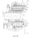
- a brake assembly 110 for mounting on an axle comprising a heat shield 200 is located on the aircraft 10 of FIG. 1A , in accordance with various embodiments.
- the brake assembly 110 for mounting on an axle typically comprises a bogie axle 112, a wheel 114 (e.g., the wheels 13A, 13B, 15A, 15B, 17A, 17B of FIG.
- a hub 116 and wheel well 118 including a hub 116 and wheel well 118, a web 120, a torque take-out assembly 122, one or more torque bars 124, a wheel rotational axis 126, a wheel well recess 128, an actuator 130, multiple brake rotors 32, multiple brake stators 34, a pressure plate 36, an end plate 38, a heat shield 200 which may have sections 142, multiple heat shield carriers 144, an air gap 146, multiple torque bar bolts 148, a torque bar pin 151, a wheel web hole 152, multiple heat shield fasteners 153, multiple rotor lugs 154, and multiple stator slots 156.
- Brake disks (e.g., the interleaved brake rotors 32 and brake stators 34) are disposed in the wheel well recess 128 of the wheel well 118.
- the brake rotors 32 and brake stators 34 may be referred to collectively as the brake stack or heat sink.
- the brake rotors 32 are typically secured to the torque bars 124 for rotating with the wheel 114, while the brake stators 34 are typically engaged with the torque take-out assembly 122.
- At least one actuator 130 is typically operable to compress the interleaved brake rotors 32 and brake stators 34 for stopping the aircraft 10 of FIG. 1A .
- the actuator 130 is shown as a hydraulically actuated piston, though pistons driven pneumatically and by electromechanical actuators are also contemplated herein.
- the pressure plate 36 and end plate 38 are disposed at opposite ends of the interleaved brake rotors 32 and brake stators 34.
- the torque take-out assembly 122 is typically secured to a stationary portion of a landing gear truck, such as a bogie beam or other landing gear strut, such that the torque take-out assembly 122 and brake stators 34 are prevented from rotating during braking of the aircraft 10 of FIG. 1A .
- the brake rotors 32 and brake stators 34 are typically fabricated from various materials, such as, for example carbon materials.
- the brake disks typically withstand and dissipate the heat generated from contact between the brake disks while braking the aircraft 10 of FIG. 1A .
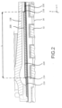
- heat shield 200 is attached to a wheel assembly, in accordance with various embodiments. As referred to herein, radially may refer to the x-direction, while axially may refer to the y-direction as shown in FIG. 1B and FIG. 2 .
- Heat shield 200 may be situated radially between the brake stack (brake rotors 32 and brake stators 34) and wheel well 118. Heat shield 200 may be configured to reduce an amount of radiative heat transferred from the brake stack to wheel well 118 during braking of the aircraft.
- Heat shield 200 may extend along an axial direction between the brake stack and wheel well 118.
- heat shield 200 may comprise a length, extending in an axial direction between the brake stack and wheel well 118.
- heat shield 200 may comprise a first structure portion 210, a second structure portion 220, and a third structure portion 230.
- First structure portion 210 may be similar in structure to third structure portion 230.
- First structure portion 210 second structure portion 220, and third structure portion 230 may each comprise a portion of the length of heat shield 200.
- heat shield 200 may begin as first structure portion 210, transition into second structure portion 220, and transition into third structure portion 230.
- a length of second structure portion 220 may be designated as L.
- L may extend an entire axial length of heat shield 200 such that a length of heat shield 200 and L are equal.
- heat shield 200 may be strategically positioned in an axial direction, in accordance with various embodiments.
- Second structure portion 220 comprising length L may be axially positioned along the y-axis such that it is positioned between the brake stack and wheel well 118 in areas that may be more likely to develop a tire fire.
- second structure portion 220 may be positioned such that it is radially inward and axially aligned with bead seat 119 of wheel well 118.
- Bead seat 119 may be more likely to cause a tire to ignite due to the close proximity of bead seat 119 to the tire, which may result in greater conductive heat transfer between bead seat 119 and the tire.
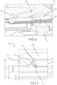
- a portion of heat shield 200 may comprise a first structure portion 210, a second structure portion 220, and a third structure portion 230.
- First structure portion 210 may transition to second structure portion 220 through first transition region 214 and second structure portion 220 may transition to third structure portion 230 through second transition region 216 (with momentary reference to FIG. 2 ).
- Second structure portion 220 may provide greater resistance to radiative heat transfer from the brake rotors 32 and brake stators 34 to wheel well 118.
- First structure portion 210 and third structure portion 230 may each comprise a first shield layer 240, an air gap layer 250 radially outward of first shield layer 240, a second shield layer 260 radially outward of air gap layer 250, a first insulation layer 270 radially outward of second shield layer 260, and a third shield layer 300 radially outward of first insulation layer 270.
- First shield layer 240 may define a cylindrical inner diameter surface of heat shield 200.
- first insulation layer 270 may be adjacent to second shield layer 260 and third shield layer 300.
- Second structure portion 220 may comprise the first shield layer 240, the air gap layer 250, the second shield layer 260, the first insulation layer 270 and the third shield layer 300. Second structure portion 220 may further comprise a foil layer 280 radially outward of first insulation layer 270, a second insulation layer 290 radially outward of foil layer 280 but radially inward of third shield layer 300. First shield layer 240, air gap layer 250, second shield layer 260, first insulation layer 270, foil layer 280, second insulation layer 290, and third shield layer 300 may be coaxial with each other. At first transition region 214, third shield layer 300 forms a first ramp extending between first structure portion 210 and second structure portion 220 of heat shield 200.
- Third shield layer 300 partially defines the first ramp, first structure portion 210, and second structure portion 220.
- the third shield layer extends from a radially outer surface of first insulation layer 270 to a radially outer surface of second insulation layer 290.
- third shield layer 300 may form a second ramp extending between second structure portion 220 and third structure portion 230 of heat shield 200.
- Third shield layer 300 may partially define the second ramp, second structure portion 220, and third structure portion 230.
- an air pocket 225 may be defined at a radially inner surface of third shield layer 300 between first insulation layer 270, foil layer 280, second insulation layer 290 and third shield layer 300. Air pocket 225 may allow cooling airflow through heat shield 200.
- a similar air pocket may be formed at second transition region 216 between first insulation layer 270, foil layer 280, second insulation layer 290, and third shield layer 300.
- First shield layer 240, second shield layer 260, and third shield layer 300 may comprise a steel alloy, in various embodiments, however, the shield layers are not limited in this regard. In various other embodiments, first shield layer 240, second shield layer 260, and third shield layer 300 may comprise other materials capable of maintaining structural integrity of heat shield 200 and shielding wheel well 118 from fires developing at or near the brake rotors 32 and brake stators 34. First shield layer 240, second shield layer 260, and third shield layer 300 may comprise thickness, denoted t1.
- t1 may be between approximately 0.005 inches (or 0.127 mm) and 0.025 inches (or 0.635 mm), between approximately 0.010 inches (or 0.254 mm) and 0.020 inches (or 0.508 mm), or between approximately 0.014 inches (or 0.356 mm) and 0.016 inches (or 0.406 mm). While in various embodiments t1 is equal in all first shield layer 240, second shield layer 260, and third shield layer 300, t1 is not limited in this regard. In various embodiments, first shield layer 240, second shield layer 260, and third shield layer 300 may comprise different thicknesses.
- First insulation layer 270 and second insulation layer 290 may comprise refractory ceramic fiber insulating papers such as those made by the company, Unifrax. First insulation layer 270 and second insulation layer 290 may also comprise insulating papers comprising alkaline earth silicates, and/or polycrystalline wool materials, however, first insulation layer 270 and second insulation layer 290 are not limited in this regard. First insulation layer 270 and second insulation layer 290 may comprise a thickness, denoted t2.
- t2 may be between approximately 0.060 inches (or 1.524 mm) and 0.080 inches (or 2.032 mm), between approximately 0.065 inches (or 1.651 mm) and 0.075 inches (or 1.905 mm), or between approximately 0.069 inches (or 1.753 mm) and 0.071 inches (1.803 mm), however, t2 is not limited in this regard.
- first insulation layer 270 and second insulation layer 290 are of equal thickness, in various embodiments, first insulation layer 270 may have a thickness greater or less than second insulation layer 290.
- Foil layer 280 may comprise a steel foil, titanium foil, or other metallic foil capable of preventing radiative heat transfer from the brake stack to wheel well 118.
- foil layer 280 may comprise a thickness, denoted t3.
- t3 may be between approximately 0.001 inches (or 0.025 mm) and 0.007 inches (or 0.178 mm), between approximately 0.002 inches (or 0.051 mm) and 0.006 inches (or 0.152 mm), or between 0.003 inches (or 0.076 mm) and 0.005 inches (or 0.127 mm), however, t3 is not limited in this regard.
- Foil layer 280 may function to prevent radiative heat transfer from the brake stack to wheel well 118 in the event flames breach first shield layer 240 and second shield layer 260 and first insulation layer 270 and second insulation layer 290 break apart.
- Heat shield 200 further comprises an air gap layer 250 situated radially between first shield layer 240 and second shield layer 260.
- Air gap layer 250 may function to minimize convective flow between first shield layer 240 and second shield layer 260.
- a flame may form radially inward of first shield layer 240.
- first shield layer 240 Prior to the flame burning through first shield layer 240, first shield layer 240 may increase in temperature.
- Air gap layer 250 may reduce the convective transfer of heat from first shield layer 240 to second shield layer 260 while first shield layer 240 is being heated by the flame. Accordingly, heat shield 200 may be more effective at reducing radiative heat transfer from the brake stack to wheel well 118 when compared with a heat shield comprising an additional layer of insulation in place of air gap layer 250. Additional layers of insulation in place of air gap layer 250 may function to keep first shield layer 240 at a higher temperature, thereby leading to a quicker burn through.
- First structure portion 210 and third structure portion 230 may comprise a thickness, denoted t4.
- t4 may be between approximately 0.100 inches (or 2.540 mm) and 0.200 inches (or 5.080 mm), between approximately 0.125 inches (or 3.175 mm) and 0.175 inches (or 4.445 mm), or between 0.152 inches (or 3.861 mm) and 0.154 inches (or 3.912 mm), however, t4 is not limited in this regard.
- t4 may comprise a greater or smaller thickness due to first shield layer 240, air gap layer 250, second shield layer 260, first insulation layer 270, and/or third shield layer 300 comprising a different thickness than disclosed in the present embodiment.
- Second structure portion 220 may comprise a different thickness, denoted t5.
- t5 may be between approximately 0.175 inches (or 4.445 mm) and 0.275 inches (or 6.985 mm), between approximately 0.200 inches (or 5.080 mm) and 0.230 inches (or 6.350 mm), or between approximately 0.227 inches (or 5.766 mm) and 0.229 inches (or 5.817 mm), however, t5 is not limited in this regard.
- t5 may comprise a greater or smaller thickness due to first shield layer 240, air gap layer 250, second shield layer 260, first insulation layer 270, foil layer 280, second insulation layer 290, and/or third shield layer 300 comprising a different thickness than disclosed in the present embodiment.
- the thickness t5 of second structure portion 220 may be thicker than the thickness t4 of first structure portion 210 in order to provide greater resistance to radiative heat transfer from the brake stack to wheel well 118. While various embodiments include a first structure portion 210, first transition region 214, second structure portion 220, second transition region 216, and third structure portion 230, the structure of heat shield 200 is not limited in this regard. In various embodiments, second structure portion 220 may extend an entire axial length of heat shield 200 to provide greater radiative heat transfer throughout an entire axial length of wheel well 118.
- Method 500 comprises forming a first shield layer defining a cylindrical inner diameter surface (Step 502).
- the method further comprises forming a second shield layer radially outward of the first shield layer such that an air gap layer is situated between the first shield layer and the second shield layer (Step 504).
- the method further comprises forming a first insulation layer radially outward of the second shield layer (Step 506).
- the method further comprises forming a foil layer radially outward of the first insulation layer (Step 508).
- the method further comprises further forming a second insulation layer radially outward of the first insulation layer (Step 510).
- the method further comprises forming a third shield layer radially outward of the second insulation layer (Step 512).
- references to "one embodiment”, “an embodiment”, “various embodiments”, etc. indicate that the embodiment described may include a particular feature, structure, or characteristic, but every embodiment may not necessarily include the particular feature, structure, or characteristic. Moreover, such phrases are not necessarily referring to the same embodiment. Further, when a particular feature, structure, or characteristic is described in connection with an embodiment, it is submitted that it is within the knowledge of one skilled in the art to affect such feature, structure, or characteristic in connection with other embodiments whether or not explicitly described. After reading the description, it will be apparent to one skilled in the relevant art(s) how to implement the invention in alternative embodiments.
Landscapes
- Engineering & Computer Science (AREA)
- General Engineering & Computer Science (AREA)
- Mechanical Engineering (AREA)
- Aviation & Aerospace Engineering (AREA)
- Braking Arrangements (AREA)
- Thermal Insulation (AREA)
Description
- The present invention relates to heat shield systems and methods, and more particularly, to heat shield systems and methods for aircraft braking systems.
- Aircraft should complete a successful Rejected Takeoff (RTO) without allowing a sustained tire fire for a time period thereafter. In that regard, heat shields may be used to tend to prevent such a fire. Heat shields are known from
US 5,002,342 ,EP 1780057 ,US 2006/124387 andGB 2172547 - A heat shield is provided as defined by claim 1.
- In various embodiments, the first shield layer, the air gap layer, the second shield layer, the first insulation layer, the foil layer, the second insulation layer, and the third shield layer may be coaxial. An air pocket may be defined between the first insulation layer, the foil layer, the second insulation layer, and the third shield layer. The first insulation layer and second insulation layer may comprise one of a refractory ceramic fiber, an alkaline earth silicate, or a polycrystalline wool material. The first insulation layer may be adjacent to the second shield layer and the third shield layer in the first structure portion and the second structure portion. The foil layer and second insulation layer may extend less than an overall axial length of the heat shield. The first shield layer, second shield layer, and third shield layer may each comprise a thickness between approximately 0.127 mm (0.005 inches) and 0.635 mm (0.025 inches).
- A brake assembly for an aircraft may comprise a brake stack, a wheel well, and a heat shield comprising a first shield layer defining a cylindrical inner diameter surface of the heat shield, the cylindrical inner diameter surface having a radius and an axis, an air gap layer radially outward of the first shield layer, a second shield layer radially outward of the air gap layer, a first insulation layer radially outward of the second shield layer, a foil layer radially outward of the second shield layer, a second insulation layer radially outward of the foil layer, and a third shield layer radially outward of the second insulation layer.
- In various embodiments, the heat shield may be situated radially between the brake stack and the wheel well. The first shield layer, the air gap layer, the second shield layer, the first insulation layer, the foil layer, the second insulation layer, and the third shield layer may be coaxial with each other. The brake assembly may further comprise an air pocket defined between the first insulation layer, the foil layer, the second insulation layer, and the third shield layer. The brake assembly may further comprise a first ramp extending from a radially outer surface of the first insulation layer to a radially outer surface of the second insulation layer and extending in an axial direction from a first structure portion to a second structure portion of the heat shield, wherein the third shield layer partially defines the first ramp, first structure portion, and second structure portion. The first insulation layer and second insulation layer may comprise one of a refractory ceramic fiber, an alkaline earth silicate, or a polycrystalline wool material.
- A method of manufacturing a heat shield is provided as defined by claim 11.
- In various embodiments, forming the second shield layer may comprise forming the second shield layer such that an air gap layer is situated between the second shield layer and the first shield layer. The heat shield layers may be formed coaxial with each other. The foil layer and second insulation layer may be formed to extend less than an overall length of the heat shield. The first insulation layer and second insulation layer may be formed from one of a refractory ceramic fiber, an alkaline earth silicate, or a polycrystalline wool material.
- The following description and the accompanying drawings. It should be understood, however, the following description and drawings are intended to be exemplary and the scope of the invention is as defined by the claims.
- The accompanying drawings are included to provide a further understanding of the present invention and are incorporated in, and constitute a part of, this specification, illustrate various embodiments, and together with the description, serve to explain the principles of the invention.
-
FIG. 1A illustrates an aircraft having a brake system comprising a heat shield, in accordance with various embodiments; -
FIG. 1B illustrates a brake assembly comprising a heat shield, in accordance with various embodiments; -
FIG. 2 illustrates a cross-sectional view of a heat shield attached to a brake assembly, in accordance with various embodiments; -
FIG. 3 illustrates an expanded cross-sectional view of the heat shield attached to a brake assembly ofFIG. 2 , in accordance with various embodiments; -
FIG. 4 illustrates a detailed view of the heat shield ofFIG. 3 , in accordance with various embodiments; and -
FIG. 5 illustrates a method of manufacturing a heat shield, in accordance with various embodiments. - The detailed description of various embodiments herein makes reference to the accompanying drawings, which show various embodiments by way of illustration. While these various embodiments are described in sufficient detail to enable those skilled in the art to practice the invention, it should be understood that other embodiments may be realized and that logical, chemical, electrical, and mechanical changes may be made without departing from the scope of the invention as defined by the claims. Thus, the detailed description herein is presented for purposes of illustration only and not of limitation.
- For example, the steps recited in any of the method or process descriptions may be executed in any order and are not necessarily limited to the order presented. Furthermore, any reference to singular includes plural embodiments, and any reference to more than one component or step may include a singular embodiment or step. Also, any reference to attached, fixed, connected, or the like may include permanent, removable, temporary, partial, full, and/or any other possible attachment option. Additionally, any reference to without contact (or similar phrases) may also include reduced contact or minimal contact.
- For example, in the context of the present invention, methods, systems, and articles may find particular use in connection with aircraft braking systems. However, various aspects of the disclosed embodiments may be adapted for performance in a variety of other systems. As such, numerous applications of the present invention may be realized.
- Various embodiments of the present invention may result in improved heat shielding between a brake stack and an aircraft tire during RTOs. Typically, when an RTO is initiated, the aircraft is traveling at a high rate of speed and aircraft brakes are activated in order to reduce the speed of the aircraft. The aircraft brakes convert kinetic energy to thermal energy through friction, leading to high temperatures in the brake stacks. The heat in a brake stack may be transferred to an aircraft tire, which increases the potential for the tire to ignite. Accordingly, heat shields may be desired to reduce heat transfer from a brake stack to a tire.
- Referring now to
FIG. 1A , in accordance with various embodiments, anaircraft 10 includes landing gear, such as a leftmain landing gear 12, a rightmain landing gear 14, andnose landing gear 16. The leftmain landing gear 12, rightmain landing gear 14, andnose landing gear 16 typically support theaircraft 10 when theaircraft 10 is not flying, thereby allowing theaircraft 10 to taxi, take off, and land without damage. In various embodiments, the leftmain landing gear 12 includes afirst wheel 13A and asecond wheel 13B coupled by anaxle 20. In various embodiments, the rightmain landing gear 14 includes afirst wheel 15A and asecond wheel 15B coupled by anaxle 22. In various embodiments, thenose landing gear 16 includes afirst nose wheel 17A and asecond nose wheel 17B coupled by anaxle 24. In various embodiments, theaircraft 10 comprises any number of landing gear(s), and each landing gear comprises any number of wheels. In various embodiments, the leftmain landing gear 12, rightmain landing gear 14, andnose landing gear 16 are retracted when theaircraft 10 is in flight. In various embodiments, one or more of the leftmain landing gear 12, rightmain landing gear 14, andnose landing gear 16 extends from an underside of afuselage 28 of theaircraft 10, or from an underside of thewings 30 thereof. - In various embodiments, the
aircraft 10 also includes a brake system that is applied to one or more of thewheels main landing gear 12, rightmain landing gear 14, and/ornose landing gear 16. Such brake systems of theaircraft 10 typically comprise a collection of assemblies, subsystems, and/or units that produce output signals for controlling the braking force and/or torque applied at one or more of thewheels main landing gear 12, rightmain landing gear 14, and/ornose landing gear 16, and each brake is typically mounted to eachwheel aircraft 10 further include a non-rotatable wheel support, thewheels - Referring now to
FIG. 1B , abrake assembly 110 for mounting on an axle comprising aheat shield 200 is located on theaircraft 10 ofFIG. 1A , in accordance with various embodiments. Thebrake assembly 110 for mounting on an axle typically comprises abogie axle 112, a wheel 114 (e.g., thewheels FIG. 1-A ) including ahub 116 and wheel well 118, aweb 120, a torque take-outassembly 122, one ormore torque bars 124, a wheelrotational axis 126, awheel well recess 128, anactuator 130,multiple brake rotors 32,multiple brake stators 34, apressure plate 36, anend plate 38, aheat shield 200 which may havesections 142, multipleheat shield carriers 144, anair gap 146, multipletorque bar bolts 148, atorque bar pin 151, awheel web hole 152, multipleheat shield fasteners 153, multiple rotor lugs 154, andmultiple stator slots 156. - Brake disks (e.g., the interleaved
brake rotors 32 and brake stators 34) are disposed in thewheel well recess 128 of thewheel well 118. Thebrake rotors 32 andbrake stators 34 may be referred to collectively as the brake stack or heat sink. Thebrake rotors 32 are typically secured to the torque bars 124 for rotating with thewheel 114, while thebrake stators 34 are typically engaged with the torque take-outassembly 122. At least oneactuator 130 is typically operable to compress the interleavedbrake rotors 32 andbrake stators 34 for stopping theaircraft 10 ofFIG. 1A . In the embodiment ofFIG. 1B , theactuator 130 is shown as a hydraulically actuated piston, though pistons driven pneumatically and by electromechanical actuators are also contemplated herein. Thepressure plate 36 andend plate 38 are disposed at opposite ends of the interleavedbrake rotors 32 andbrake stators 34. - Through compression of the
brake rotors 32 andbrake stators 34 between thepressure plate 36 andend plate 38, the resulting frictional contact slows, stops, and/or prevents rotation of thewheel 114. The torque take-outassembly 122 is typically secured to a stationary portion of a landing gear truck, such as a bogie beam or other landing gear strut, such that the torque take-outassembly 122 andbrake stators 34 are prevented from rotating during braking of theaircraft 10 ofFIG. 1A . Thebrake rotors 32 andbrake stators 34 are typically fabricated from various materials, such as, for example carbon materials. The brake disks typically withstand and dissipate the heat generated from contact between the brake disks while braking theaircraft 10 ofFIG. 1A . - Referring now to
FIG. 2 ,heat shield 200 is attached to a wheel assembly, in accordance with various embodiments. As referred to herein, radially may refer to the x-direction, while axially may refer to the y-direction as shown inFIG. 1B andFIG. 2 .Heat shield 200 may be situated radially between the brake stack (brakerotors 32 and brake stators 34) andwheel well 118.Heat shield 200 may be configured to reduce an amount of radiative heat transferred from the brake stack to wheel well 118 during braking of the aircraft.Heat shield 200 may extend along an axial direction between the brake stack andwheel well 118. For example,heat shield 200 may comprise a length, extending in an axial direction between the brake stack andwheel well 118. As will be discussed below with reference toFIG. 3 and FIG. 4 ,heat shield 200 may comprise afirst structure portion 210, asecond structure portion 220, and athird structure portion 230.First structure portion 210 may be similar in structure tothird structure portion 230.First structure portion 210second structure portion 220, andthird structure portion 230 may each comprise a portion of the length ofheat shield 200. For example, moving from left to right in the y-direction,heat shield 200 may begin asfirst structure portion 210, transition intosecond structure portion 220, and transition intothird structure portion 230. A length ofsecond structure portion 220 may be designated as L. In various other embodiments, L may extend an entire axial length ofheat shield 200 such that a length ofheat shield 200 and L are equal. - Referring now to
FIG. 3 ,heat shield 200 may be strategically positioned in an axial direction, in accordance with various embodiments.Second structure portion 220 comprising length L may be axially positioned along the y-axis such that it is positioned between the brake stack and wheel well 118 in areas that may be more likely to develop a tire fire. For example,second structure portion 220 may be positioned such that it is radially inward and axially aligned withbead seat 119 ofwheel well 118.Bead seat 119 may be more likely to cause a tire to ignite due to the close proximity ofbead seat 119 to the tire, which may result in greater conductive heat transfer betweenbead seat 119 and the tire. - Referring now to
FIG. 4 , a detailed view of the heat shield ofFIG. 3 is depicted, in accordance with various embodiments. As previously stated, a portion ofheat shield 200 may comprise afirst structure portion 210, asecond structure portion 220, and athird structure portion 230.First structure portion 210 may transition tosecond structure portion 220 throughfirst transition region 214 andsecond structure portion 220 may transition tothird structure portion 230 through second transition region 216 (with momentary reference toFIG. 2 ).Second structure portion 220 may provide greater resistance to radiative heat transfer from thebrake rotors 32 andbrake stators 34 towheel well 118. -
First structure portion 210 andthird structure portion 230 may each comprise afirst shield layer 240, anair gap layer 250 radially outward offirst shield layer 240, asecond shield layer 260 radially outward ofair gap layer 250, afirst insulation layer 270 radially outward ofsecond shield layer 260, and athird shield layer 300 radially outward offirst insulation layer 270.First shield layer 240 may define a cylindrical inner diameter surface ofheat shield 200. Infirst structure portion 210 andthird structure portion 230,first insulation layer 270 may be adjacent tosecond shield layer 260 andthird shield layer 300. -
Second structure portion 220 may comprise thefirst shield layer 240, theair gap layer 250, thesecond shield layer 260, thefirst insulation layer 270 and thethird shield layer 300.Second structure portion 220 may further comprise afoil layer 280 radially outward offirst insulation layer 270, asecond insulation layer 290 radially outward offoil layer 280 but radially inward ofthird shield layer 300.First shield layer 240,air gap layer 250,second shield layer 260,first insulation layer 270,foil layer 280,second insulation layer 290, andthird shield layer 300 may be coaxial with each other. Atfirst transition region 214,third shield layer 300 forms a first ramp extending betweenfirst structure portion 210 andsecond structure portion 220 ofheat shield 200.Third shield layer 300 partially defines the first ramp,first structure portion 210, andsecond structure portion 220. The third shield layer extends from a radially outer surface offirst insulation layer 270 to a radially outer surface ofsecond insulation layer 290. Atsecond transition region 216,third shield layer 300 may form a second ramp extending betweensecond structure portion 220 andthird structure portion 230 ofheat shield 200.Third shield layer 300 may partially define the second ramp,second structure portion 220, andthird structure portion 230. Atfirst transition region 214, anair pocket 225 may be defined at a radially inner surface ofthird shield layer 300 betweenfirst insulation layer 270,foil layer 280,second insulation layer 290 andthird shield layer 300.Air pocket 225 may allow cooling airflow throughheat shield 200. A similar air pocket may be formed atsecond transition region 216 betweenfirst insulation layer 270,foil layer 280,second insulation layer 290, andthird shield layer 300. -
First shield layer 240,second shield layer 260, andthird shield layer 300 may comprise a steel alloy, in various embodiments, however, the shield layers are not limited in this regard. In various other embodiments,first shield layer 240,second shield layer 260, andthird shield layer 300 may comprise other materials capable of maintaining structural integrity ofheat shield 200 and shielding wheel well 118 from fires developing at or near thebrake rotors 32 andbrake stators 34.First shield layer 240,second shield layer 260, andthird shield layer 300 may comprise thickness, denoted t1. In various embodiments, t1 may be between approximately 0.005 inches (or 0.127 mm) and 0.025 inches (or 0.635 mm), between approximately 0.010 inches (or 0.254 mm) and 0.020 inches (or 0.508 mm), or between approximately 0.014 inches (or 0.356 mm) and 0.016 inches (or 0.406 mm). While in various embodiments t1 is equal in allfirst shield layer 240,second shield layer 260, andthird shield layer 300, t1 is not limited in this regard. In various embodiments,first shield layer 240,second shield layer 260, andthird shield layer 300 may comprise different thicknesses. -
First insulation layer 270 andsecond insulation layer 290 may comprise refractory ceramic fiber insulating papers such as those made by the company, Unifrax.First insulation layer 270 andsecond insulation layer 290 may also comprise insulating papers comprising alkaline earth silicates, and/or polycrystalline wool materials, however,first insulation layer 270 andsecond insulation layer 290 are not limited in this regard.First insulation layer 270 andsecond insulation layer 290 may comprise a thickness, denoted t2. In various embodiments, t2 may be between approximately 0.060 inches (or 1.524 mm) and 0.080 inches (or 2.032 mm), between approximately 0.065 inches (or 1.651 mm) and 0.075 inches (or 1.905 mm), or between approximately 0.069 inches (or 1.753 mm) and 0.071 inches (1.803 mm), however, t2 is not limited in this regard. Further, while in various embodimentsfirst insulation layer 270 andsecond insulation layer 290 are of equal thickness, in various embodiments,first insulation layer 270 may have a thickness greater or less thansecond insulation layer 290. -
Foil layer 280 may comprise a steel foil, titanium foil, or other metallic foil capable of preventing radiative heat transfer from the brake stack towheel well 118. In various embodiments,foil layer 280 may comprise a thickness, denoted t3. In various embodiments, t3 may be between approximately 0.001 inches (or 0.025 mm) and 0.007 inches (or 0.178 mm), between approximately 0.002 inches (or 0.051 mm) and 0.006 inches (or 0.152 mm), or between 0.003 inches (or 0.076 mm) and 0.005 inches (or 0.127 mm), however, t3 is not limited in this regard.Foil layer 280 may function to prevent radiative heat transfer from the brake stack to wheel well 118 in the event flames breachfirst shield layer 240 andsecond shield layer 260 andfirst insulation layer 270 andsecond insulation layer 290 break apart. -
Heat shield 200 further comprises anair gap layer 250 situated radially betweenfirst shield layer 240 andsecond shield layer 260.Air gap layer 250 may function to minimize convective flow betweenfirst shield layer 240 andsecond shield layer 260. For example, during an RTO, a flame may form radially inward offirst shield layer 240. Prior to the flame burning throughfirst shield layer 240,first shield layer 240 may increase in temperature.Air gap layer 250 may reduce the convective transfer of heat fromfirst shield layer 240 tosecond shield layer 260 whilefirst shield layer 240 is being heated by the flame. Accordingly,heat shield 200 may be more effective at reducing radiative heat transfer from the brake stack to wheel well 118 when compared with a heat shield comprising an additional layer of insulation in place ofair gap layer 250. Additional layers of insulation in place ofair gap layer 250 may function to keepfirst shield layer 240 at a higher temperature, thereby leading to a quicker burn through. -
First structure portion 210 andthird structure portion 230 may comprise a thickness, denoted t4. In various embodiments, t4 may be between approximately 0.100 inches (or 2.540 mm) and 0.200 inches (or 5.080 mm), between approximately 0.125 inches (or 3.175 mm) and 0.175 inches (or 4.445 mm), or between 0.152 inches (or 3.861 mm) and 0.154 inches (or 3.912 mm), however, t4 is not limited in this regard. In various embodiments, t4 may comprise a greater or smaller thickness due tofirst shield layer 240,air gap layer 250,second shield layer 260,first insulation layer 270, and/orthird shield layer 300 comprising a different thickness than disclosed in the present embodiment.Second structure portion 220 may comprise a different thickness, denoted t5. In various embodiments, t5 may be between approximately 0.175 inches (or 4.445 mm) and 0.275 inches (or 6.985 mm), between approximately 0.200 inches (or 5.080 mm) and 0.230 inches (or 6.350 mm), or between approximately 0.227 inches (or 5.766 mm) and 0.229 inches (or 5.817 mm), however, t5 is not limited in this regard. In various embodiments, t5 may comprise a greater or smaller thickness due tofirst shield layer 240,air gap layer 250,second shield layer 260,first insulation layer 270,foil layer 280,second insulation layer 290, and/orthird shield layer 300 comprising a different thickness than disclosed in the present embodiment. In various embodiments, the thickness t5 ofsecond structure portion 220 may be thicker than the thickness t4 offirst structure portion 210 in order to provide greater resistance to radiative heat transfer from the brake stack towheel well 118. While various embodiments include afirst structure portion 210,first transition region 214,second structure portion 220,second transition region 216, andthird structure portion 230, the structure ofheat shield 200 is not limited in this regard. In various embodiments,second structure portion 220 may extend an entire axial length ofheat shield 200 to provide greater radiative heat transfer throughout an entire axial length ofwheel well 118. - A block diagram illustrating a
method 500 for manufacturing a heat shield is illustrated inFIG. 5 , in accordance with various embodiments.Method 500 comprises forming a first shield layer defining a cylindrical inner diameter surface (Step 502). The method further comprises forming a second shield layer radially outward of the first shield layer such that an air gap layer is situated between the first shield layer and the second shield layer (Step 504). The method further comprises forming a first insulation layer radially outward of the second shield layer (Step 506). The method further comprises forming a foil layer radially outward of the first insulation layer (Step 508). The method further comprises further forming a second insulation layer radially outward of the first insulation layer (Step 510). The method further comprises forming a third shield layer radially outward of the second insulation layer (Step 512). - Benefits, other advantages, and solutions to problems have been described herein with regard to specific embodiments. Furthermore, the connecting lines shown in the various figures contained herein are intended to represent exemplary functional relationships and/or physical couplings between the various elements. It should be noted that many alternative or additional functional relationships or physical connections may be present in a practical system. However, the benefits, advantages, solutions to problems, and any elements that may cause any benefit, advantage, or solution to occur or become more pronounced are not to be construed as critical, required, or essential features or elements of the invention. The scope of the invention is accordingly to be limited by nothing other than the appended claims, in which reference to an element in the singular is not intended to mean "one and only one" unless explicitly so stated, but rather "one or more." Moreover, where a phrase similar to "at least one of A, B, or C" is used in the claims, it is intended that the phrase be interpreted to mean that A alone may be present in an embodiment, B alone may be present in an embodiment, C alone may be present in an embodiment, or that any combination of the elements A, B and C may be present in a single embodiment; for example, A and B, A and C, B and C, or A and B and C. Different cross-hatching is used throughout the figures to denote different parts but not necessarily to denote the same or different materials.
- Methods, systems, and computer-readable media are provided herein. In the detailed description herein, references to "one embodiment", "an embodiment", "various embodiments", etc., indicate that the embodiment described may include a particular feature, structure, or characteristic, but every embodiment may not necessarily include the particular feature, structure, or characteristic. Moreover, such phrases are not necessarily referring to the same embodiment. Further, when a particular feature, structure, or characteristic is described in connection with an embodiment, it is submitted that it is within the knowledge of one skilled in the art to affect such feature, structure, or characteristic in connection with other embodiments whether or not explicitly described. After reading the description, it will be apparent to one skilled in the relevant art(s) how to implement the invention in alternative embodiments.
Claims (14)
- A heat shield comprising,a first shield layer (240) defining a cylindrical inner diameter surface of the heat shield, the cylindrical inner diameter surface having a radius and an axis;an air gap layer (250) radially outward of the first shield layer;a second shield layer (260) radially outward of the air gap layer; anda first insulation layer (270) radially outward of the second shield layer; and characterized by:a foil layer (280) radially outward of the first insulation layer;a second insulation layer (290) radially outward of the foil layer; anda third shield layer (300) radially outward of the second insulation layer, wherein the third shield layer (300) extends from a radially outer surface of the first insulation layer (270) to a radially outer surface of the second insulation layer (290), and wherein the third shield layer forms a first ramp (214) extending from the radially outer surface of the first insulation layer to a radially outer surface of the second insulation layer, and wherein the first ramp extends in an axial direction from a first structure portion (210) of the heat shield to a second structure portion (220) of the heat shield, and wherein the third shield layer partially defines the first structure portion and second structure portion
- The heat shield of claim 1, wherein the first shield layer, the air gap layer, the second shield layer, the first insulation layer, the foil layer, the second insulation layer, and the third shield layer are coaxial.
- The heat shield of claim 1 or 2, further comprising an air pocket (225) defined between the first insulation layer, the foil layer, the second insulation layer, and the third shield layer.
- The heat shield of claim 1, 2 or 3, wherein the third shield layer forms a second ramp (216) extending from the radially outer surface of the second insulation layer to the radially outer surface of the first insulation layer, wherein the second ramp extends in the axial direction from the second structure portion (220) of the heat shield to a third structure portion (230) of the heat shield, and wherein the third shield layer partially defines the third structure portion.
- The heat shield of any preceding claim, wherein the first insulation layer and second insulation layer comprise one of a refractory ceramic fiber, an alkaline earth silicate, or a polycrystalline wool material.
- The heat shield of claim 4, wherein the first insulation layer is adjacent to the second shield layer and the third shield layer in the first structure portion and the third structure portion.
- The heat shield of any preceding claim, wherein the foil layer and second insulation layer extend less than an overall axial length of the heat shield.
- The heat shield of any preceding claim, wherein the first shield layer, second shield layer, and third shield layer each comprise a thickness between approximately 0.127 mm (0.005 inches) and 0.635 mm (0.025 inches).
- A brake assembly for an aircraft comprising,a brake stack (32, 34);a wheel well (118); anda heat shield (200 as claimed in any preceding claim situated radially between the brake stack and the wheel well.
- The brake assembly of claim 9, wherein the third shield layer forms a first ramp (214) extending from the radially outer surface of the first insulation layer to the radially outer surface of the second insulation layer, and wherein the first ramp extends in an axial direction from a first structure portion (210) of the heat shield to a second structure portion (220) of the heat shield, and wherein the second structure portion (220) of the heat shield is positioned situated radially inward and axially aligned with a bead seat (119) of between the brake stack and the wheel well
- A method of manufacturing a heat shield comprising,forming a first shield layer (240) defining a cylindrical inner diameter surface;forming a second shield layer (260) radially outward of the first shield layer; andforming a first insulation layer (270) radially outward of the second shield layer; and characterized by:forming a foil layer (280) radially outward of the first insulation layer;forming a second insulation layer (290) radially outward of the foil layer; andforming a third shield layer (300) radially outward of the second insulation layer and extending from a radially outer surface of the first insulation layer (270) to a radially outer surface of the second insulation layer (290), wherein the third shield layer forms a first ramp (214) extending from the radially outer surface of the first insulation layer to a radially outer surface of the second insulation layer, and wherein the first ramp extends in an axial direction from a first structure portion (210) of the heat shield to a second structure portion (220) of the heat shield, and wherein the third shield layer partially defines the first structure portion and second structure portion.
- The method of claim 11, wherein forming the second shield layer comprises forming the second shield layer such that an air gap layer is situated between the second shield layer and the first shield layer.
- The method of claim 11 or 12, wherein the first heat shield layer and the second heat shield layer are formed coaxial with the third heat shield layer.
- The method of claim 11, 12 or 13, wherein the foil layer and second insulation layer are formed to extend less than an overall length of the heat shield.
Applications Claiming Priority (1)
| Application Number | Priority Date | Filing Date | Title |
|---|---|---|---|
| US15/918,176 US10400839B1 (en) | 2018-03-12 | 2018-03-12 | Aircraft brake heat shield |
Publications (2)
| Publication Number | Publication Date |
|---|---|
| EP3539834A1 EP3539834A1 (en) | 2019-09-18 |
| EP3539834B1 true EP3539834B1 (en) | 2023-07-19 |
Family
ID=65801917
Family Applications (1)
| Application Number | Title | Priority Date | Filing Date |
|---|---|---|---|
| EP19162337.0A Active EP3539834B1 (en) | 2018-03-12 | 2019-03-12 | Aircraft brake heat shield |
Country Status (2)
| Country | Link |
|---|---|
| US (1) | US10400839B1 (en) |
| EP (1) | EP3539834B1 (en) |
Family Cites Families (19)
| Publication number | Priority date | Publication date | Assignee | Title |
|---|---|---|---|---|
| GB878973A (en) | 1959-06-22 | 1961-10-04 | Bendix Corp | A safety system for pneumatic-tired aircraft wheel and brake assemblies |
| US4017123A (en) | 1976-04-02 | 1977-04-12 | The Bendix Corporation | Dual layer heat shield for wheels |
| GB2172547B (en) * | 1985-03-19 | 1989-02-01 | Mitsubishi Metal Corp | Heat insulating material and heat-insulated conduit |
| US5002342A (en) * | 1989-12-28 | 1991-03-26 | Aircraft Braking Systems Corporation | Brake assembly heat shield |
| US5111577A (en) * | 1990-01-22 | 1992-05-12 | Atd Corporation | Pad including heat sink and thermal insulation areas |
| CH684206A5 (en) * | 1990-11-12 | 1994-07-29 | Matec Holding | Disposable heat shield. |
| US5248013A (en) | 1992-02-13 | 1993-09-28 | The B. F. Goodrich Company | Heatshield installation for aircraft brake |
| GB9217795D0 (en) * | 1992-08-21 | 1992-10-07 | T & N Technology Ltd | Heat shields |
| US5424139A (en) * | 1994-01-10 | 1995-06-13 | Lydall, Inc. | Metal heat insulator |
| US5524406A (en) * | 1994-03-24 | 1996-06-11 | Atd Corporation | Insulating apparatus and method for attaching an insulating pad to a support |
| WO1998056573A1 (en) * | 1997-06-09 | 1998-12-17 | Atd Corporation | Shaped multilayer metal foil shield structures and method of making |
| US20020098316A1 (en) * | 2001-01-25 | 2002-07-25 | Butler Richard M. | Multilayer foil insulation and method for manufacturing |
| US6797402B2 (en) * | 2001-09-28 | 2004-09-28 | Dana Corporation | Insulated heat shield with waved edge |
| EP1780057A3 (en) * | 2001-10-10 | 2007-05-16 | Goodrich Corporation | Heat shield assembly for an aircraft wheel and brake assembly |
| DE10253832A1 (en) * | 2002-11-18 | 2004-05-27 | Carcoustics Tech Center Gmbh | Sound absorbing heat shield for motor vehicles to protect chassis from heat, and suppress sound emitted by exhaust silencers is formed entirely of aluminum materials. |
| US6966402B2 (en) * | 2003-06-02 | 2005-11-22 | Dana Corporation | Acoustical heat shield |
| US7585559B2 (en) * | 2003-06-03 | 2009-09-08 | Intellectual Property Holdings, Llc | Foam barrier heat shield |
| US8523108B2 (en) | 2011-03-24 | 2013-09-03 | Goodrich Corporation | Heat shield installation for aircraft wheel to improve convective cooling of aircraft brake |
| MX2015010931A (en) * | 2013-02-22 | 2016-07-19 | Interface Performance Materials Inc | Lightweight thermal shield. |
-
2018
- 2018-03-12 US US15/918,176 patent/US10400839B1/en active Active
-
2019
- 2019-03-12 EP EP19162337.0A patent/EP3539834B1/en active Active
Also Published As
| Publication number | Publication date |
|---|---|
| EP3539834A1 (en) | 2019-09-18 |
| US10400839B1 (en) | 2019-09-03 |
| US20190277357A1 (en) | 2019-09-12 |
Similar Documents
| Publication | Publication Date | Title |
|---|---|---|
| EP3521161B1 (en) | Laminated dimpled foil metallic heat shield | |
| EP3480072B1 (en) | Shield attachment device | |
| US10167912B2 (en) | Plate assemblies including floating wear linings for multi-disk brake systems and methods for reducing vibration in a multi-disk brake system | |
| EP3647622A1 (en) | Segmented heat shield with reduced interlayer thermal conduction | |
| EP3569400B1 (en) | Carbon nanotube based heat shield | |
| JPS61248926A (en) | Heat-resistant disk brake for wheel of aircraft, etc. | |
| EP3726087B1 (en) | Multiple layer piston insulator for hydraulic brake actuator | |
| EP3539834B1 (en) | Aircraft brake heat shield | |
| EP3524517B1 (en) | Insulated torque plate foot assembly | |
| US11428287B2 (en) | Hydraulic brake actuator piston adjuster assembly | |
| CA2677453C (en) | Braking | |
| EP3453614B1 (en) | Aircraft brake torque and clamp force reaction through landing gear structure | |
| EP4011724A1 (en) | Wheel assembly with torque bar bracket ribs | |
| US10309468B2 (en) | Torque plate barrel having blended barrel support pedestal | |
| EP1650460B1 (en) | Aircraft brake actuator | |
| EP3925874B1 (en) | Aircraft wheel torque bar spacer | |
| EP4420942A1 (en) | Brake assembly with electric brake actuators and method | |
| EP4299942A1 (en) | Failsafe piston pressure path | |
| EP3978776A1 (en) | Carbon brake stack assembly for improved life |
Legal Events
| Date | Code | Title | Description |
|---|---|---|---|
| PUAI | Public reference made under article 153(3) epc to a published international application that has entered the european phase |
Free format text: ORIGINAL CODE: 0009012 |
|
| STAA | Information on the status of an ep patent application or granted ep patent |
Free format text: STATUS: THE APPLICATION HAS BEEN PUBLISHED |
|
| AK | Designated contracting states |
Kind code of ref document: A1 Designated state(s): AL AT BE BG CH CY CZ DE DK EE ES FI FR GB GR HR HU IE IS IT LI LT LU LV MC MK MT NL NO PL PT RO RS SE SI SK SM TR |
|
| AX | Request for extension of the european patent |
Extension state: BA ME |
|
| STAA | Information on the status of an ep patent application or granted ep patent |
Free format text: STATUS: REQUEST FOR EXAMINATION WAS MADE |
|
| 17P | Request for examination filed |
Effective date: 20191120 |
|
| RBV | Designated contracting states (corrected) |
Designated state(s): AL AT BE BG CH CY CZ DE DK EE ES FI FR GB GR HR HU IE IS IT LI LT LU LV MC MK MT NL NO PL PT RO RS SE SI SK SM TR |
|
| STAA | Information on the status of an ep patent application or granted ep patent |
Free format text: STATUS: EXAMINATION IS IN PROGRESS |
|
| 17Q | First examination report despatched |
Effective date: 20210416 |
|
| GRAP | Despatch of communication of intention to grant a patent |
Free format text: ORIGINAL CODE: EPIDOSNIGR1 |
|
| STAA | Information on the status of an ep patent application or granted ep patent |
Free format text: STATUS: GRANT OF PATENT IS INTENDED |
|
| INTG | Intention to grant announced |
Effective date: 20230206 |
|
| RIN1 | Information on inventor provided before grant (corrected) |
Inventor name: SCHROEDER, DOUG Inventor name: MAY, WILLIAM P. Inventor name: LEIVA, ORLY |
|
| GRAS | Grant fee paid |
Free format text: ORIGINAL CODE: EPIDOSNIGR3 |
|
| GRAA | (expected) grant |
Free format text: ORIGINAL CODE: 0009210 |
|
| STAA | Information on the status of an ep patent application or granted ep patent |
Free format text: STATUS: THE PATENT HAS BEEN GRANTED |
|
| AK | Designated contracting states |
Kind code of ref document: B1 Designated state(s): AL AT BE BG CH CY CZ DE DK EE ES FI FR GB GR HR HU IE IS IT LI LT LU LV MC MK MT NL NO PL PT RO RS SE SI SK SM TR |
|
| REG | Reference to a national code |
Ref country code: GB Ref legal event code: FG4D |
|
| REG | Reference to a national code |
Ref country code: CH Ref legal event code: EP |
|
| REG | Reference to a national code |
Ref country code: DE Ref legal event code: R096 Ref document number: 602019032854 Country of ref document: DE |
|
| REG | Reference to a national code |
Ref country code: IE Ref legal event code: FG4D |
|
| P01 | Opt-out of the competence of the unified patent court (upc) registered |
Effective date: 20230922 |
|
| REG | Reference to a national code |
Ref country code: LT Ref legal event code: MG9D |
|
| REG | Reference to a national code |
Ref country code: NL Ref legal event code: MP Effective date: 20230719 |
|
| REG | Reference to a national code |
Ref country code: AT Ref legal event code: MK05 Ref document number: 1589169 Country of ref document: AT Kind code of ref document: T Effective date: 20230719 |
|
| PG25 | Lapsed in a contracting state [announced via postgrant information from national office to epo] |
Ref country code: NL Free format text: LAPSE BECAUSE OF FAILURE TO SUBMIT A TRANSLATION OF THE DESCRIPTION OR TO PAY THE FEE WITHIN THE PRESCRIBED TIME-LIMIT Effective date: 20230719 |
|
| PG25 | Lapsed in a contracting state [announced via postgrant information from national office to epo] |
Ref country code: GR Free format text: LAPSE BECAUSE OF FAILURE TO SUBMIT A TRANSLATION OF THE DESCRIPTION OR TO PAY THE FEE WITHIN THE PRESCRIBED TIME-LIMIT Effective date: 20231020 |
|
| PG25 | Lapsed in a contracting state [announced via postgrant information from national office to epo] |
Ref country code: IS Free format text: LAPSE BECAUSE OF FAILURE TO SUBMIT A TRANSLATION OF THE DESCRIPTION OR TO PAY THE FEE WITHIN THE PRESCRIBED TIME-LIMIT Effective date: 20231119 |
|
| PG25 | Lapsed in a contracting state [announced via postgrant information from national office to epo] |
Ref country code: SE Free format text: LAPSE BECAUSE OF FAILURE TO SUBMIT A TRANSLATION OF THE DESCRIPTION OR TO PAY THE FEE WITHIN THE PRESCRIBED TIME-LIMIT Effective date: 20230719 Ref country code: RS Free format text: LAPSE BECAUSE OF FAILURE TO SUBMIT A TRANSLATION OF THE DESCRIPTION OR TO PAY THE FEE WITHIN THE PRESCRIBED TIME-LIMIT Effective date: 20230719 Ref country code: PT Free format text: LAPSE BECAUSE OF FAILURE TO SUBMIT A TRANSLATION OF THE DESCRIPTION OR TO PAY THE FEE WITHIN THE PRESCRIBED TIME-LIMIT Effective date: 20231120 Ref country code: NO Free format text: LAPSE BECAUSE OF FAILURE TO SUBMIT A TRANSLATION OF THE DESCRIPTION OR TO PAY THE FEE WITHIN THE PRESCRIBED TIME-LIMIT Effective date: 20231019 Ref country code: LV Free format text: LAPSE BECAUSE OF FAILURE TO SUBMIT A TRANSLATION OF THE DESCRIPTION OR TO PAY THE FEE WITHIN THE PRESCRIBED TIME-LIMIT Effective date: 20230719 Ref country code: LT Free format text: LAPSE BECAUSE OF FAILURE TO SUBMIT A TRANSLATION OF THE DESCRIPTION OR TO PAY THE FEE WITHIN THE PRESCRIBED TIME-LIMIT Effective date: 20230719 Ref country code: IS Free format text: LAPSE BECAUSE OF FAILURE TO SUBMIT A TRANSLATION OF THE DESCRIPTION OR TO PAY THE FEE WITHIN THE PRESCRIBED TIME-LIMIT Effective date: 20231119 Ref country code: HR Free format text: LAPSE BECAUSE OF FAILURE TO SUBMIT A TRANSLATION OF THE DESCRIPTION OR TO PAY THE FEE WITHIN THE PRESCRIBED TIME-LIMIT Effective date: 20230719 Ref country code: GR Free format text: LAPSE BECAUSE OF FAILURE TO SUBMIT A TRANSLATION OF THE DESCRIPTION OR TO PAY THE FEE WITHIN THE PRESCRIBED TIME-LIMIT Effective date: 20231020 Ref country code: FI Free format text: LAPSE BECAUSE OF FAILURE TO SUBMIT A TRANSLATION OF THE DESCRIPTION OR TO PAY THE FEE WITHIN THE PRESCRIBED TIME-LIMIT Effective date: 20230719 Ref country code: AT Free format text: LAPSE BECAUSE OF FAILURE TO SUBMIT A TRANSLATION OF THE DESCRIPTION OR TO PAY THE FEE WITHIN THE PRESCRIBED TIME-LIMIT Effective date: 20230719 |
|
| PG25 | Lapsed in a contracting state [announced via postgrant information from national office to epo] |
Ref country code: PL Free format text: LAPSE BECAUSE OF FAILURE TO SUBMIT A TRANSLATION OF THE DESCRIPTION OR TO PAY THE FEE WITHIN THE PRESCRIBED TIME-LIMIT Effective date: 20230719 |
|
| REG | Reference to a national code |
Ref country code: DE Ref legal event code: R097 Ref document number: 602019032854 Country of ref document: DE |
|
| PG25 | Lapsed in a contracting state [announced via postgrant information from national office to epo] |
Ref country code: ES Free format text: LAPSE BECAUSE OF FAILURE TO SUBMIT A TRANSLATION OF THE DESCRIPTION OR TO PAY THE FEE WITHIN THE PRESCRIBED TIME-LIMIT Effective date: 20230719 |
|
| PG25 | Lapsed in a contracting state [announced via postgrant information from national office to epo] |
Ref country code: SM Free format text: LAPSE BECAUSE OF FAILURE TO SUBMIT A TRANSLATION OF THE DESCRIPTION OR TO PAY THE FEE WITHIN THE PRESCRIBED TIME-LIMIT Effective date: 20230719 Ref country code: RO Free format text: LAPSE BECAUSE OF FAILURE TO SUBMIT A TRANSLATION OF THE DESCRIPTION OR TO PAY THE FEE WITHIN THE PRESCRIBED TIME-LIMIT Effective date: 20230719 Ref country code: ES Free format text: LAPSE BECAUSE OF FAILURE TO SUBMIT A TRANSLATION OF THE DESCRIPTION OR TO PAY THE FEE WITHIN THE PRESCRIBED TIME-LIMIT Effective date: 20230719 Ref country code: EE Free format text: LAPSE BECAUSE OF FAILURE TO SUBMIT A TRANSLATION OF THE DESCRIPTION OR TO PAY THE FEE WITHIN THE PRESCRIBED TIME-LIMIT Effective date: 20230719 Ref country code: DK Free format text: LAPSE BECAUSE OF FAILURE TO SUBMIT A TRANSLATION OF THE DESCRIPTION OR TO PAY THE FEE WITHIN THE PRESCRIBED TIME-LIMIT Effective date: 20230719 Ref country code: CZ Free format text: LAPSE BECAUSE OF FAILURE TO SUBMIT A TRANSLATION OF THE DESCRIPTION OR TO PAY THE FEE WITHIN THE PRESCRIBED TIME-LIMIT Effective date: 20230719 Ref country code: SK Free format text: LAPSE BECAUSE OF FAILURE TO SUBMIT A TRANSLATION OF THE DESCRIPTION OR TO PAY THE FEE WITHIN THE PRESCRIBED TIME-LIMIT Effective date: 20230719 |
|
| PGFP | Annual fee paid to national office [announced via postgrant information from national office to epo] |
Ref country code: GB Payment date: 20240220 Year of fee payment: 6 |
|
| PLBE | No opposition filed within time limit |
Free format text: ORIGINAL CODE: 0009261 |
|
| STAA | Information on the status of an ep patent application or granted ep patent |
Free format text: STATUS: NO OPPOSITION FILED WITHIN TIME LIMIT |
|
| PG25 | Lapsed in a contracting state [announced via postgrant information from national office to epo] |
Ref country code: IT Free format text: LAPSE BECAUSE OF FAILURE TO SUBMIT A TRANSLATION OF THE DESCRIPTION OR TO PAY THE FEE WITHIN THE PRESCRIBED TIME-LIMIT Effective date: 20230719 |
|
| PGFP | Annual fee paid to national office [announced via postgrant information from national office to epo] |
Ref country code: FR Payment date: 20240220 Year of fee payment: 6 |
|
| 26N | No opposition filed |
Effective date: 20240422 |
|
| PG25 | Lapsed in a contracting state [announced via postgrant information from national office to epo] |
Ref country code: SI Free format text: LAPSE BECAUSE OF FAILURE TO SUBMIT A TRANSLATION OF THE DESCRIPTION OR TO PAY THE FEE WITHIN THE PRESCRIBED TIME-LIMIT Effective date: 20230719 |