EP3539816A1 - Verfahren zum laden eines energiespeichers eines fahrzeugs mit einer modularen ladevorrichtung bei hohem gesamtwirkungsgrad - Google Patents
Verfahren zum laden eines energiespeichers eines fahrzeugs mit einer modularen ladevorrichtung bei hohem gesamtwirkungsgrad Download PDFInfo
- Publication number
- EP3539816A1 EP3539816A1 EP18020605.4A EP18020605A EP3539816A1 EP 3539816 A1 EP3539816 A1 EP 3539816A1 EP 18020605 A EP18020605 A EP 18020605A EP 3539816 A1 EP3539816 A1 EP 3539816A1
- Authority
- EP
- European Patent Office
- Prior art keywords
- charging
- power supply
- supply modules
- approximation
- determined
- Prior art date
- Legal status (The legal status is an assumption and is not a legal conclusion. Google has not performed a legal analysis and makes no representation as to the accuracy of the status listed.)
- Granted
Links
Images



Classifications
-
- B—PERFORMING OPERATIONS; TRANSPORTING
- B60—VEHICLES IN GENERAL
- B60L—PROPULSION OF ELECTRICALLY-PROPELLED VEHICLES; SUPPLYING ELECTRIC POWER FOR AUXILIARY EQUIPMENT OF ELECTRICALLY-PROPELLED VEHICLES; ELECTRODYNAMIC BRAKE SYSTEMS FOR VEHICLES IN GENERAL; MAGNETIC SUSPENSION OR LEVITATION FOR VEHICLES; MONITORING OPERATING VARIABLES OF ELECTRICALLY-PROPELLED VEHICLES; ELECTRIC SAFETY DEVICES FOR ELECTRICALLY-PROPELLED VEHICLES
- B60L53/00—Methods of charging batteries, specially adapted for electric vehicles; Charging stations or on-board charging equipment therefor; Exchange of energy storage elements in electric vehicles
- B60L53/20—Methods of charging batteries, specially adapted for electric vehicles; Charging stations or on-board charging equipment therefor; Exchange of energy storage elements in electric vehicles characterised by converters located in the vehicle
- B60L53/22—Constructional details or arrangements of charging converters specially adapted for charging electric vehicles
-
- B—PERFORMING OPERATIONS; TRANSPORTING
- B60—VEHICLES IN GENERAL
- B60L—PROPULSION OF ELECTRICALLY-PROPELLED VEHICLES; SUPPLYING ELECTRIC POWER FOR AUXILIARY EQUIPMENT OF ELECTRICALLY-PROPELLED VEHICLES; ELECTRODYNAMIC BRAKE SYSTEMS FOR VEHICLES IN GENERAL; MAGNETIC SUSPENSION OR LEVITATION FOR VEHICLES; MONITORING OPERATING VARIABLES OF ELECTRICALLY-PROPELLED VEHICLES; ELECTRIC SAFETY DEVICES FOR ELECTRICALLY-PROPELLED VEHICLES
- B60L53/00—Methods of charging batteries, specially adapted for electric vehicles; Charging stations or on-board charging equipment therefor; Exchange of energy storage elements in electric vehicles
-
- B—PERFORMING OPERATIONS; TRANSPORTING
- B60—VEHICLES IN GENERAL
- B60L—PROPULSION OF ELECTRICALLY-PROPELLED VEHICLES; SUPPLYING ELECTRIC POWER FOR AUXILIARY EQUIPMENT OF ELECTRICALLY-PROPELLED VEHICLES; ELECTRODYNAMIC BRAKE SYSTEMS FOR VEHICLES IN GENERAL; MAGNETIC SUSPENSION OR LEVITATION FOR VEHICLES; MONITORING OPERATING VARIABLES OF ELECTRICALLY-PROPELLED VEHICLES; ELECTRIC SAFETY DEVICES FOR ELECTRICALLY-PROPELLED VEHICLES
- B60L53/00—Methods of charging batteries, specially adapted for electric vehicles; Charging stations or on-board charging equipment therefor; Exchange of energy storage elements in electric vehicles
- B60L53/10—Methods of charging batteries, specially adapted for electric vehicles; Charging stations or on-board charging equipment therefor; Exchange of energy storage elements in electric vehicles characterised by the energy transfer between the charging station and the vehicle
- B60L53/11—DC charging controlled by the charging station, e.g. mode 4
-
- B—PERFORMING OPERATIONS; TRANSPORTING
- B60—VEHICLES IN GENERAL
- B60L—PROPULSION OF ELECTRICALLY-PROPELLED VEHICLES; SUPPLYING ELECTRIC POWER FOR AUXILIARY EQUIPMENT OF ELECTRICALLY-PROPELLED VEHICLES; ELECTRODYNAMIC BRAKE SYSTEMS FOR VEHICLES IN GENERAL; MAGNETIC SUSPENSION OR LEVITATION FOR VEHICLES; MONITORING OPERATING VARIABLES OF ELECTRICALLY-PROPELLED VEHICLES; ELECTRIC SAFETY DEVICES FOR ELECTRICALLY-PROPELLED VEHICLES
- B60L53/00—Methods of charging batteries, specially adapted for electric vehicles; Charging stations or on-board charging equipment therefor; Exchange of energy storage elements in electric vehicles
- B60L53/10—Methods of charging batteries, specially adapted for electric vehicles; Charging stations or on-board charging equipment therefor; Exchange of energy storage elements in electric vehicles characterised by the energy transfer between the charging station and the vehicle
- B60L53/14—Conductive energy transfer
-
- B—PERFORMING OPERATIONS; TRANSPORTING
- B60—VEHICLES IN GENERAL
- B60L—PROPULSION OF ELECTRICALLY-PROPELLED VEHICLES; SUPPLYING ELECTRIC POWER FOR AUXILIARY EQUIPMENT OF ELECTRICALLY-PROPELLED VEHICLES; ELECTRODYNAMIC BRAKE SYSTEMS FOR VEHICLES IN GENERAL; MAGNETIC SUSPENSION OR LEVITATION FOR VEHICLES; MONITORING OPERATING VARIABLES OF ELECTRICALLY-PROPELLED VEHICLES; ELECTRIC SAFETY DEVICES FOR ELECTRICALLY-PROPELLED VEHICLES
- B60L53/00—Methods of charging batteries, specially adapted for electric vehicles; Charging stations or on-board charging equipment therefor; Exchange of energy storage elements in electric vehicles
- B60L53/60—Monitoring or controlling charging stations
- B60L53/62—Monitoring or controlling charging stations in response to charging parameters, e.g. current, voltage or electrical charge
-
- H—ELECTRICITY
- H02—GENERATION; CONVERSION OR DISTRIBUTION OF ELECTRIC POWER
- H02J—ELECTRIC POWER NETWORKS; CIRCUIT ARRANGEMENTS OR SYSTEMS FOR SUPPLYING OR DISTRIBUTING ELECTRIC POWER; SYSTEMS FOR STORING ELECTRIC ENERGY
- H02J1/00—Circuit arrangements for DC mains or DC distribution networks
- H02J1/10—Parallel operation of DC sources
-
- H—ELECTRICITY
- H02—GENERATION; CONVERSION OR DISTRIBUTION OF ELECTRIC POWER
- H02J—ELECTRIC POWER NETWORKS; CIRCUIT ARRANGEMENTS OR SYSTEMS FOR SUPPLYING OR DISTRIBUTING ELECTRIC POWER; SYSTEMS FOR STORING ELECTRIC ENERGY
- H02J1/00—Circuit arrangements for DC mains or DC distribution networks
- H02J1/10—Parallel operation of DC sources
- H02J1/102—Parallel operation of DC sources being switching converters
-
- H—ELECTRICITY
- H02—GENERATION; CONVERSION OR DISTRIBUTION OF ELECTRIC POWER
- H02J—ELECTRIC POWER NETWORKS; CIRCUIT ARRANGEMENTS OR SYSTEMS FOR SUPPLYING OR DISTRIBUTING ELECTRIC POWER; SYSTEMS FOR STORING ELECTRIC ENERGY
- H02J7/00—Circuit arrangements for charging or discharging batteries or for supplying loads from batteries
-
- H—ELECTRICITY
- H02—GENERATION; CONVERSION OR DISTRIBUTION OF ELECTRIC POWER
- H02J—ELECTRIC POWER NETWORKS; CIRCUIT ARRANGEMENTS OR SYSTEMS FOR SUPPLYING OR DISTRIBUTING ELECTRIC POWER; SYSTEMS FOR STORING ELECTRIC ENERGY
- H02J7/00—Circuit arrangements for charging or discharging batteries or for supplying loads from batteries
- H02J7/90—Regulation of charging or discharging current or voltage
-
- H—ELECTRICITY
- H02—GENERATION; CONVERSION OR DISTRIBUTION OF ELECTRIC POWER
- H02M—APPARATUS FOR CONVERSION BETWEEN AC AND AC, BETWEEN AC AND DC, OR BETWEEN DC AND DC, AND FOR USE WITH MAINS OR SIMILAR POWER SUPPLY SYSTEMS; CONVERSION OF DC OR AC INPUT POWER INTO SURGE OUTPUT POWER; CONTROL OR REGULATION THEREOF
- H02M3/00—Conversion of DC power input into DC power output
- H02M3/02—Conversion of DC power input into DC power output without intermediate conversion into AC
- H02M3/04—Conversion of DC power input into DC power output without intermediate conversion into AC by static converters
- H02M3/10—Conversion of DC power input into DC power output without intermediate conversion into AC by static converters using discharge tubes with control electrode or semiconductor devices with control electrode
- H02M3/125—Conversion of DC power input into DC power output without intermediate conversion into AC by static converters using discharge tubes with control electrode or semiconductor devices with control electrode using devices of a thyratron or thyristor type requiring extinguishing means
- H02M3/135—Conversion of DC power input into DC power output without intermediate conversion into AC by static converters using discharge tubes with control electrode or semiconductor devices with control electrode using devices of a thyratron or thyristor type requiring extinguishing means using semiconductor devices only
- H02M3/137—Conversion of DC power input into DC power output without intermediate conversion into AC by static converters using discharge tubes with control electrode or semiconductor devices with control electrode using devices of a thyratron or thyristor type requiring extinguishing means using semiconductor devices only with automatic control of output voltage or current, e.g. switching regulators
- H02M3/142—Conversion of DC power input into DC power output without intermediate conversion into AC by static converters using discharge tubes with control electrode or semiconductor devices with control electrode using devices of a thyratron or thyristor type requiring extinguishing means using semiconductor devices only with automatic control of output voltage or current, e.g. switching regulators including plural semiconductor devices as final control devices for a single load
-
- B—PERFORMING OPERATIONS; TRANSPORTING
- B60—VEHICLES IN GENERAL
- B60L—PROPULSION OF ELECTRICALLY-PROPELLED VEHICLES; SUPPLYING ELECTRIC POWER FOR AUXILIARY EQUIPMENT OF ELECTRICALLY-PROPELLED VEHICLES; ELECTRODYNAMIC BRAKE SYSTEMS FOR VEHICLES IN GENERAL; MAGNETIC SUSPENSION OR LEVITATION FOR VEHICLES; MONITORING OPERATING VARIABLES OF ELECTRICALLY-PROPELLED VEHICLES; ELECTRIC SAFETY DEVICES FOR ELECTRICALLY-PROPELLED VEHICLES
- B60L2210/00—Converter types
- B60L2210/10—DC to DC converters
-
- B—PERFORMING OPERATIONS; TRANSPORTING
- B60—VEHICLES IN GENERAL
- B60L—PROPULSION OF ELECTRICALLY-PROPELLED VEHICLES; SUPPLYING ELECTRIC POWER FOR AUXILIARY EQUIPMENT OF ELECTRICALLY-PROPELLED VEHICLES; ELECTRODYNAMIC BRAKE SYSTEMS FOR VEHICLES IN GENERAL; MAGNETIC SUSPENSION OR LEVITATION FOR VEHICLES; MONITORING OPERATING VARIABLES OF ELECTRICALLY-PROPELLED VEHICLES; ELECTRIC SAFETY DEVICES FOR ELECTRICALLY-PROPELLED VEHICLES
- B60L2240/00—Control parameters of input or output; Target parameters
- B60L2240/40—Drive Train control parameters
- B60L2240/52—Drive Train control parameters related to converters
- B60L2240/527—Voltage
-
- B—PERFORMING OPERATIONS; TRANSPORTING
- B60—VEHICLES IN GENERAL
- B60L—PROPULSION OF ELECTRICALLY-PROPELLED VEHICLES; SUPPLYING ELECTRIC POWER FOR AUXILIARY EQUIPMENT OF ELECTRICALLY-PROPELLED VEHICLES; ELECTRODYNAMIC BRAKE SYSTEMS FOR VEHICLES IN GENERAL; MAGNETIC SUSPENSION OR LEVITATION FOR VEHICLES; MONITORING OPERATING VARIABLES OF ELECTRICALLY-PROPELLED VEHICLES; ELECTRIC SAFETY DEVICES FOR ELECTRICALLY-PROPELLED VEHICLES
- B60L2240/00—Control parameters of input or output; Target parameters
- B60L2240/40—Drive Train control parameters
- B60L2240/52—Drive Train control parameters related to converters
- B60L2240/529—Current
-
- B—PERFORMING OPERATIONS; TRANSPORTING
- B60—VEHICLES IN GENERAL
- B60L—PROPULSION OF ELECTRICALLY-PROPELLED VEHICLES; SUPPLYING ELECTRIC POWER FOR AUXILIARY EQUIPMENT OF ELECTRICALLY-PROPELLED VEHICLES; ELECTRODYNAMIC BRAKE SYSTEMS FOR VEHICLES IN GENERAL; MAGNETIC SUSPENSION OR LEVITATION FOR VEHICLES; MONITORING OPERATING VARIABLES OF ELECTRICALLY-PROPELLED VEHICLES; ELECTRIC SAFETY DEVICES FOR ELECTRICALLY-PROPELLED VEHICLES
- B60L2240/00—Control parameters of input or output; Target parameters
- B60L2240/40—Drive Train control parameters
- B60L2240/54—Drive Train control parameters related to batteries
- B60L2240/547—Voltage
-
- B—PERFORMING OPERATIONS; TRANSPORTING
- B60—VEHICLES IN GENERAL
- B60L—PROPULSION OF ELECTRICALLY-PROPELLED VEHICLES; SUPPLYING ELECTRIC POWER FOR AUXILIARY EQUIPMENT OF ELECTRICALLY-PROPELLED VEHICLES; ELECTRODYNAMIC BRAKE SYSTEMS FOR VEHICLES IN GENERAL; MAGNETIC SUSPENSION OR LEVITATION FOR VEHICLES; MONITORING OPERATING VARIABLES OF ELECTRICALLY-PROPELLED VEHICLES; ELECTRIC SAFETY DEVICES FOR ELECTRICALLY-PROPELLED VEHICLES
- B60L2240/00—Control parameters of input or output; Target parameters
- B60L2240/40—Drive Train control parameters
- B60L2240/54—Drive Train control parameters related to batteries
- B60L2240/549—Current
-
- Y—GENERAL TAGGING OF NEW TECHNOLOGICAL DEVELOPMENTS; GENERAL TAGGING OF CROSS-SECTIONAL TECHNOLOGIES SPANNING OVER SEVERAL SECTIONS OF THE IPC; TECHNICAL SUBJECTS COVERED BY FORMER USPC CROSS-REFERENCE ART COLLECTIONS [XRACs] AND DIGESTS
- Y02—TECHNOLOGIES OR APPLICATIONS FOR MITIGATION OR ADAPTATION AGAINST CLIMATE CHANGE
- Y02T—CLIMATE CHANGE MITIGATION TECHNOLOGIES RELATED TO TRANSPORTATION
- Y02T10/00—Road transport of goods or passengers
- Y02T10/60—Other road transportation technologies with climate change mitigation effect
- Y02T10/70—Energy storage systems for electromobility, e.g. batteries
-
- Y—GENERAL TAGGING OF NEW TECHNOLOGICAL DEVELOPMENTS; GENERAL TAGGING OF CROSS-SECTIONAL TECHNOLOGIES SPANNING OVER SEVERAL SECTIONS OF THE IPC; TECHNICAL SUBJECTS COVERED BY FORMER USPC CROSS-REFERENCE ART COLLECTIONS [XRACs] AND DIGESTS
- Y02—TECHNOLOGIES OR APPLICATIONS FOR MITIGATION OR ADAPTATION AGAINST CLIMATE CHANGE
- Y02T—CLIMATE CHANGE MITIGATION TECHNOLOGIES RELATED TO TRANSPORTATION
- Y02T10/00—Road transport of goods or passengers
- Y02T10/60—Other road transportation technologies with climate change mitigation effect
- Y02T10/7072—Electromobility specific charging systems or methods for batteries, ultracapacitors, supercapacitors or double-layer capacitors
-
- Y—GENERAL TAGGING OF NEW TECHNOLOGICAL DEVELOPMENTS; GENERAL TAGGING OF CROSS-SECTIONAL TECHNOLOGIES SPANNING OVER SEVERAL SECTIONS OF THE IPC; TECHNICAL SUBJECTS COVERED BY FORMER USPC CROSS-REFERENCE ART COLLECTIONS [XRACs] AND DIGESTS
- Y02—TECHNOLOGIES OR APPLICATIONS FOR MITIGATION OR ADAPTATION AGAINST CLIMATE CHANGE
- Y02T—CLIMATE CHANGE MITIGATION TECHNOLOGIES RELATED TO TRANSPORTATION
- Y02T10/00—Road transport of goods or passengers
- Y02T10/60—Other road transportation technologies with climate change mitigation effect
- Y02T10/72—Electric energy management in electromobility
-
- Y—GENERAL TAGGING OF NEW TECHNOLOGICAL DEVELOPMENTS; GENERAL TAGGING OF CROSS-SECTIONAL TECHNOLOGIES SPANNING OVER SEVERAL SECTIONS OF THE IPC; TECHNICAL SUBJECTS COVERED BY FORMER USPC CROSS-REFERENCE ART COLLECTIONS [XRACs] AND DIGESTS
- Y02—TECHNOLOGIES OR APPLICATIONS FOR MITIGATION OR ADAPTATION AGAINST CLIMATE CHANGE
- Y02T—CLIMATE CHANGE MITIGATION TECHNOLOGIES RELATED TO TRANSPORTATION
- Y02T10/00—Road transport of goods or passengers
- Y02T10/80—Technologies aiming to reduce greenhouse gasses emissions common to all road transportation technologies
- Y02T10/92—Energy efficient charging or discharging systems for batteries, ultracapacitors, supercapacitors or double-layer capacitors specially adapted for vehicles
-
- Y—GENERAL TAGGING OF NEW TECHNOLOGICAL DEVELOPMENTS; GENERAL TAGGING OF CROSS-SECTIONAL TECHNOLOGIES SPANNING OVER SEVERAL SECTIONS OF THE IPC; TECHNICAL SUBJECTS COVERED BY FORMER USPC CROSS-REFERENCE ART COLLECTIONS [XRACs] AND DIGESTS
- Y02—TECHNOLOGIES OR APPLICATIONS FOR MITIGATION OR ADAPTATION AGAINST CLIMATE CHANGE
- Y02T—CLIMATE CHANGE MITIGATION TECHNOLOGIES RELATED TO TRANSPORTATION
- Y02T90/00—Enabling technologies or technologies with a potential or indirect contribution to GHG emissions mitigation
- Y02T90/10—Technologies relating to charging of electric vehicles
- Y02T90/12—Electric charging stations
-
- Y—GENERAL TAGGING OF NEW TECHNOLOGICAL DEVELOPMENTS; GENERAL TAGGING OF CROSS-SECTIONAL TECHNOLOGIES SPANNING OVER SEVERAL SECTIONS OF THE IPC; TECHNICAL SUBJECTS COVERED BY FORMER USPC CROSS-REFERENCE ART COLLECTIONS [XRACs] AND DIGESTS
- Y02—TECHNOLOGIES OR APPLICATIONS FOR MITIGATION OR ADAPTATION AGAINST CLIMATE CHANGE
- Y02T—CLIMATE CHANGE MITIGATION TECHNOLOGIES RELATED TO TRANSPORTATION
- Y02T90/00—Enabling technologies or technologies with a potential or indirect contribution to GHG emissions mitigation
- Y02T90/10—Technologies relating to charging of electric vehicles
- Y02T90/14—Plug-in electric vehicles
Definitions
- the invention relates to a method for charging an energy storage device of a vehicle with a charging device, which provides a charging current and a charging voltage at an operating point, wherein the charging device has a plurality of parallel-connected power supply modules.
- the method may be used to charge electric vehicles or plug-in hybrid vehicles.
- a plurality of power supply modules are connected in parallel so that the output currents provided by the power supply modules add up to the charging current of the charging device.
- the efficiency of a power supply module depends on the output current of the respective power supply module and the charging voltage of the charging device. If the charging current or the charging voltage changes during the charging of the energy store, the overall efficiency of the charging device also changes.
- the optimization step several possible operating points of the loading device are considered, i. several combinations of charging current and charging voltage.
- a distribution of the charging current to the individual power supply modules is determined, in which the overall efficiency of the charging device, i. the efficiency of the parallel connection of the power supply modules, is maximum.
- the desired operating point i. depending on the desired charge current and the desired charge voltage
- a selection of the distribution that has been determined for this operating point in the optimization step is always done with high overall efficiency.
- the optimization step is performed before charging the energy storage takes place, ie before the energy storage is connected to the charging device.
- the optimization step can be carried out in advance, so that during the actual loading in the charging step, only a selection can be made from the previously determined current distributions.
- an approximation of the efficiency of a single energy supply module in dependence on an output voltage and an output current of the energy supply module is determined.
- the approximation in the approximation step takes place by means of linear approximation or quadratic approximation or cubic approximation.
- the efficiency of the power supply module is determined for a plurality of modular operating points, the modular operating points each comprising an output voltage and an output current of the energy supply module.
- the efficiency of the power supply module can be determined as a quotient of output power and input power of the power supply module.
- the measuring step is preferably carried out as part of a charging process preceding the current charging step, for example during the preceding charging of another energy store of another vehicle.
- the efficiency of the energy supply module determined in the measuring step for a plurality of modular working points can be stored in a module memory of the energy supply module. To the To reduce storage requirements, in the measurement step support points, z. B. for a Newton approximation, are stored in the module memory.
- the distribution of the charging current to the active power supply modules is determined by means of a gradient method.
- the distribution of the charging current to a determined number of active power supply modules in equal parts can be used as a starting point. Starting from this starting point, the distribution of the charging current to the individual energy supply modules can be optimized by the gradient method.
- a table is applied, which comprises a distribution of the charging current to the parallel-connected power supply modules for different operating points, wherein the selection in the charging step is based on the table.
- a distribution of the charging current to the individual energy supply modules can be stored in the table for each operating point at which a maximum overall efficiency of the charging device can be achieved.
- the distribution stored in the table may comprise, for each power supply module, a partial charging current assigned to the power supply module, wherein the partial charging currents are identical or different.
- the selection of the distribution of the charging current to the individual energy supply modules by means of a classifier takes place.
- the classifier may determine a number of active power modules, particularly where the active power modules have an identical output current.
- the classifier is trained in a training step between the optimization step and the loading step.
- the actual overall efficiency of the charging device is determined in the charging step.
- a measurement of the charging current and the charging voltage can take place.
- input voltages and input currents of the parallel-connected power supply modules can be measured.
- the actual Efficiency of the individual power supply modules determined.
- a measurement of the output current and the output voltage of the power supply modules can be carried out.
- input voltages and input currents of the parallel-connected power supply modules can be measured.
- several measurements of the charging current and the charging voltage of the charging device can take place, wherein different energy supply modules are activated and from these measurements the output current and the output voltage or the efficiency of the individual energy supply modules are determined.
- the parallel-connected power supply modules preferably have a DC-DC converter. Via an output of the DC-DC converter, the output current and the output voltage of the power supply module can be delivered.
- the power supply modules can output an output current in the range of 0 A to 100 A, more preferably from 0 A to 50 A.
- the output voltage of the power supply modules, and thus the charging voltage in a range between 0 V and 1000 V, for example in a range between 0 V and 950 V, adjustable.
- FIG. 1 1 is a block diagram of an exemplary embodiment of a charging device 3 that is suitable for charging an energy store 2 of a vehicle 1, for example an electric vehicle or a plug-in hybrid vehicle.
- the charging device 3 has a plurality of identical energy supply modules 4, which are connected in parallel.
- the power supply modules 4 each comprise a DC-DC converter, via whose output an output current I M1 , I M2 , I MN and an output voltage U are provided.
- the charging device 4 for charging the energy storage device 2 can provide a charging current I L designed as a direct current, which corresponds to the sum of the output currents I M1 , I M2 , I MN of the energy supply modules 4.
- the charging device 3 according to the exemplary embodiment is configured as a DC high-power charging device and can provide a charging current I L in the range from 0 A to 500 A at a charging voltage U of 0 V to 1000 V.
- the efficiency ⁇ N of a power supply module 4 as a function of the output current I MN and the output or charging voltage U is shown. It can be seen that the efficiency ⁇ N with increasing output current I MN initially assumes a maximum and then decreases with a further increase of the output current I MN. In addition, the efficiency ⁇ N increases with increasing output or charging voltage U.
- the charging device 3 is operated by a method according to an embodiment of the invention.
- a distribution of the charging current I L to the parallel-connected power supply modules 4 is determined in an optimization step for a plurality of predetermined operating points, in which the charging device 3 has a maximum overall efficiency.
- a distribution of the voltage is then dependent on a predetermined charging current I L and a predetermined charging voltage U Charging current I L selected on the individual power supply modules 4 of the charging device 3, in which the charging device 3 has a maximum overall efficiency.
- the Fig. 3 shows in a first flowchart an optimization step 105 of the method, which is preferably carried out before the actual charging of the energy storage device 2. This means that these method steps can be performed before an electrical connection between the charging device 3 and the energy storage 2 of the vehicle 1 is established.
- an in Fig. 3 Not shown approximation performed in which an approximation of the efficiency ⁇ N of a single power module 4 in dependence on the output voltage U and the output current I MN of the power supply module 4 is determined.
- the efficiency ⁇ N of the power supply module 4 is determined for several modular working points.
- the approximation step 105 is performed in order to be able to indicate the efficiency ⁇ N of the power supply module 4 also for those modular operating points for which no measurements were carried out in the measuring step.
- the approximation can be done for example by means of linear approximation or quadratic approximation or cubic approximation, wherein these possibilities will be discussed.
- approximation step 105 the approximation of losses for a predefined charging voltage U and a predetermined charging current I L is initially carried out in a first partial step 101 on the basis of measured data of output voltage U, output current I NM and efficiency ⁇ N of the energy supply modules 4 For An optimization is carried out at this operating point, as a result of which a distribution of the charging current I L to the parallel-connected power supply modules 4 is determined, at which the overall efficiency of the charging device 3 - ie the parallel connection of the power supply modules 4 - is maximal.
- This determination can be made with methods of linear or non-linear, in particular quadratic, programming or symmetrical loss calculation or genetic algorithms.
- the first partial step 101 and the second partial step 102 are performed iteratively for a plurality of operating points, cf. Loop 104.
- a distribution of the charging current I L to the parallel-connected power supply modules 4 is provided for a plurality of predetermined operating points, in which the charging device 3 has a maximum overall efficiency.
- the Fig. 4 shows a training step 107, which is preferably carried out before the actual charging of the energy storage 2.
- a classifier is trained in the training step 107, which can be used for selecting the suitable distribution during loading.
- the trained classifier is stored in the loading device 3, in particular in a storage unit of the loading device 3.
- the result 106 of the optimization can be stored in a table which can be read out during later loading.
- the optimization step 105 may be performed during the charging of the energy store 2. In this respect, the optimization step 105 and the charging step can be carried out while the energy store 2 is connected to the charging device 3.
- the classifier is initialized in a configuration step 110. This can be done, for example, by reading the result 108 of the training step 107 from a memory unit of the charging device 3.
- a loop variable is set to a start value.
- a query step 112 the current operating point of the charging device 3 is determined, ie the actual charging current I L and the actual charging voltage U.
- a query step 112 following the charging step 113 is a function of the charging current I L and the charging voltage U, a distribution of the charging current I. L is selected for the individual power supply modules 4 of the charging device 3, in which the charging device 3 has a maximum overall efficiency.
- the selection of this distribution preferably takes place by means of the classifier trained in the training step 107, which classifier can be designed, for example, as a decision tree classifier. Alternatively, the selection can be made by reading out a table stored in the loading device 3.
- the interrogation step 112 and the charging step 113 are repeated periodically, so that the distribution of the charging current I L can be tracked to the power supply modules 4 at any changes in the operating point of the charging device 3.
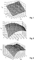
- Fig. 6 are shown several measured values of the efficiency of a power supply module 4 as a function of output voltage U and output current I MN of the power supply module 4, as they can be determined for example in a measuring step of the method according to the invention.
- the Fig. 7 shows a linear approximation of the efficiency Fig. 6
- Fig. 8 is a quadratic approximation of the efficiency Fig. 6
- Fig. 9 a cubic approximation of the efficiency Fig. 6 shown.
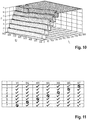
- a three-dimensional representation of a table with approximately 1400 x 4900 entries is shown in which the optimization result determined in the optimization step 105 is included, wherein in the optimization step 105, a number n of active power modules 4 is determined, which, ignoring aging effects and component tolerances identical Output current I M1 , I M2 , I NM have.
- the charging current I L is distributed in equal parts to a number n of active power supply modules 4. Therefore, only the number n of the active power supply modules 4 must be stored in the table.
- the actual overall efficiency of the charging device 3 or the actual efficiency of the individual energy supply modules 4 can be determined.
- the output current I MN and the output voltage U or the efficiency ⁇ N of the individual power supply modules 4 can then be determined from these measurements.
- a possible flowchart for such a measurement sequence is the example of a charging device 3 with a total of seven power supply modules M1, M2, M3, M4, M5, M6, M7 in FIG Fig. 11 shown.
- the operating state of the individual power supply modules M1, M2, M3, M4, M5, M6, M7 is shown in seven successive time steps T, wherein a hook is an active power supply module M1, M2, M3, M4, M5, M6, M7 and a crossed-out circle denotes an inactive power supply module M1, M2, M3, M4, M5, M6, M7.
Landscapes
- Engineering & Computer Science (AREA)
- Power Engineering (AREA)
- Transportation (AREA)
- Mechanical Engineering (AREA)
- Charge And Discharge Circuits For Batteries Or The Like (AREA)
- Secondary Cells (AREA)
- Life Sciences & Earth Sciences (AREA)
- Electric Propulsion And Braking For Vehicles (AREA)
- Ecology (AREA)
- Environmental Sciences (AREA)
- Biodiversity & Conservation Biology (AREA)
- Environmental & Geological Engineering (AREA)
- Atmospheric Sciences (AREA)
Abstract
- In einem Optimierungsschritt (105) wird für mehrere vorgegebene Arbeitspunkte jeweils eine Verteilung des Ladestroms (IL) auf die parallel geschalteten Energieversorgungsmodule (4) ermittelt, bei welcher die Ladevorrichtung (3) einen maximalen Gesamtwirkungsgrad aufweist;
- In einem dem Optimierungsschritt (105) nachfolgenden Ladeschritt (113) wird in Abhängigkeit von einem vorgegebenen Ladestrom (IL) und einer vorgegebenen Ladespannung (U) eine Verteilung des Ladestroms (IL) auf die einzelnen Energieversorgungsmodule (4) der Ladevorrichtung (3) ausgewählt, bei welcher die Ladevorrichtung (3) einen maximalen Gesamtwirkungsgrad aufweist.
Description
- Die Erfindung betrifft ein Verfahren zum Laden eines Energiespeichers eines Fahrzeugs mit einer Ladevorrichtung, die in einem Arbeitspunkt einen Ladestrom und eine Ladespannung bereitstellt, wobei die Ladevorrichtung mehrere parallel geschaltete Energieversorgungsmodule aufweist.
- Das Verfahren kann beispielsweise zum Laden von Elektrofahrzeugen oder Plug-In-Hybrid-Fahrzeugen Anwendung finden.
- Bei einer Ladevorrichtung der eingangs genannten Art sind mehrere Energieversorgungsmodule parallelgeschaltet, so dass sich die von den Energieversorgungsmodulen bereitgestellten Ausgangsströme zu dem Ladestrom der Ladevorrichtung addieren. Der Wirkungsgrad eines Energieversorgungsmoduls hängt von dem Ausgangsstrom des jeweiligen Energieversorgungsmoduls und der Ladespannung der Ladevorrichtung ab. Verändert sich nun der Ladestrom bzw. die Ladespannung während des Ladens des Energiespeichers, so ändert sich auch der Gesamtwirkungsgrad der Ladevorrichtung.
- Grundsätzlich ist es wünschenswert, die Ladevorrichtung derart zu betreiben, dass ihr Gesamtwirkungsgrad möglichst hoch ist. Vor diesem Hintergrund stellt sich die Aufgabe, einen Betrieb einer Ladevorrichtung mit mehreren parallelgeschalteten Energieversorgungsmodulen bei hohem Gesamtwirkungsgrad zu ermöglichen.
- Vorgeschlagen wird zur Lösung der Aufgabe ein Verfahren zum Laden eines Energiespeichers eines Fahrzeugs mit einer Ladevorrichtung, die in einem Arbeitspunkt einen Ladestrom und eine Ladespannung bereitstellt, wobei die Ladevorrichtung mehrere parallel geschaltete Energieversorgungsmodule aufweist, mit den folgenden Verfahrensschritten:
- In einem Optimierungsschritt wird für mehrere vorgegebene Arbeitspunkte jeweils eine Verteilung des Ladestroms auf die parallel geschalteten Energieversorgungsmodule ermittelt, bei welcher die Ladevorrichtung einen maximalen Gesamtwirkungsgrad aufweist;
- In einem dem Optimierungsschritt nachfolgenden Ladeschritt wird in Abhängigkeit von einem vorgegebenen Ladestrom und einer vorgegebenen Ladespannung eine Verteilung des Ladestroms auf die einzelnen Energieversorgungsmodule der Ladevorrichtung ausgewählt, bei welcher die Ladevorrichtung einen maximalen Gesamtwirkungsgrad aufweist.
- Erfindungsgemäß werden in dem Optimierungsschritt mehrere mögliche Arbeitspunkte der Ladevorrichtung betrachtet, d.h. mehrere Kombinationen aus Ladestrom und Ladespannung. Für die betrachteten Arbeitspunkte wird jeweils eine Verteilung des Ladestroms auf die einzelnen Energieversorgungsmodule bestimmt, bei welcher der Gesamtwirkungsgrad der Ladevorrichtung, d.h. der Wirkungsgrad der Parallelschaltung der Energieversorgungsmodule, maximal ist. In dem Ladeschritt erfolgt dann in Abhängigkeit von dem gewünschten Arbeitspunkt, d.h. in Abhängigkeit von dem gewünschten Ladestrom und der gewünschten Ladespannung, eine Auswahl der Verteilung, die für diesen Arbeitspunkt im Optimierungsschritt ermittelt worden ist. Auf diese Weise kann der Betrieb der Ladevorrichtung beim Laden des Energiespeichers des Fahrzeugs, beispielsweise einer Batterie oder eines Akkumulators, stets mit hohem Gesamtwirkungsgrad erfolgen.
- Bevorzugt wird der Optimierungsschritt durchgeführt, bevor das Laden des Energiespeichers erfolgt, d.h. bevor der Energiespeicher mit der Ladevorrichtung verbunden wird. Insofern kann der Optimierungsschritt vorab durchgeführt werden, so dass während des eigentlichen Ladens in dem Ladeschritt lediglich eine Auswahl aus den vorab bestimmten Strom-Verteilungen erfolgen kann.
- Gemäß einer vorteilhaften Ausgestaltung ist vorgesehen, dass in einem dem Optimierungsschritt vorhergehenden Approximationsschritt eine Approximation des Wirkungsgrads eines einzelnen Energieversorgungsmoduls in Abhängigkeit von einer Ausgangsspannung und einem Ausgangsstrom des Energieversorgungsmoduls ermittelt wird. Durch die Bereitstellung dieser Approximation wird es möglich, für beliebige Kombinationen von Ausgangsspannung und Ausgangsstrom eines einzelnen Energieversorgungsmoduls einen näherungsweisen Wirkungsgrad des Energieversorgungsmoduls anzugeben.
- Bevorzugt ist es, wenn die Approximation in dem Approximationsschritt mittels linearer Approximation oder quadratischer Approximation oder kubischer Approximation erfolgt.
- Gemäß einer vorteilhaften Ausgestaltung ist vorgesehen, dass in einem dem Approximationsschritt vorhergehenden Messschritt der Wirkungsgrad des Energieversorgungsmoduls für mehrere Modularbeitspunkte ermittelt wird, wobei die Modularbeitspunkte jeweils eine Ausgangsspannung und einen Ausgangsstrom des Energieversorgungsmoduls umfassen. Der Wirkungsgrad des Energieversorgungsmoduls kann als Quotient von Ausgangsleistung und Eingangsleistung des Energieversorgungsmoduls bestimmt werden. Der Messschritt wird bevorzugt als Teil eines dem aktuellen Ladeschritt vorhergehenden Ladevorgangs, beispielsweise beim vorhergehenden Laden eines anderen Energiespeichers eines anderen Fahrzeugs, durchgeführt. Optional kann der in dem Messschritt ermittelte Wirkungsgrad des Energieversorgungsmoduls für mehrere Modularbeitspunkte in einem Modulspeicher des Energieversorgungsmoduls gespeichert werden. Um den Speicherbedarf zu reduzieren, können in dem Messchritt Stützstellen, z. B. für eine Newton-Approximation, in dem Modulspeicher gespeichert werden.
- Als vorteilhaft hat es sich erwiesen, wenn in dem Optimierungsschritt eine Anzahl aktiver Energieversorgungsmodule ermittelt wird, wobei die aktiven Energieversorgungsmodule einen identischen Ausgangsstrom aufweisen. Eine derartige Ausgestaltung bringt den Vorteil mit sich, dass die Energieversorgungsmodule auf einen identischen Arbeitspunkt eingestellt werden können, d.h. eine identische Vorgabe für einen Ausgangsstrom und eine Ausgangsspannung erhalten können und lediglich die Anzahl der aktiven Energieversorgungsmodule eingestellt werden muss. Eine derartige Ausgestaltung ist insbesondere dann von Vorteil, wenn die Ladevorrichtung baugleiche Energieversorgungsmodule aufweist.
- In diesem Zusammenhang ist es bevorzugt, wenn in dem Optimierungsschritt ausgehend von der ermittelten Anzahl aktiver Energieversorgungsmodule die Verteilung des Ladestroms auf die aktiven Energieversorgungsmodule mittels eines Gradientenverfahrens ermittelt wird. Die Aufteilung des Ladestroms auf eine ermittelte Anzahl von aktiven Energieversorgungsmodulen zu gleichen Teilen kann als Startpunkt genutzt werden. Ausgehend von diesem Startpunkt kann die Verteilung des Ladestroms auf die einzelnen Energieversorgungsmodule durch das Gradientenverfahren optimiert werden.
- Gemäß einer vorteilhaften Ausgestaltung ist vorgesehen, dass in dem Optimierungsschritt eine Tabelle angelegt wird, die eine Verteilung des Ladestroms auf die parallel geschalteten Energieversorgungsmodule für verschiedene Arbeitspunkte umfasst, wobei die Auswahl in dem Ladeschritt anhand der Tabelle erfolgt. Insofern kann in der Tabelle für jeden Arbeitspunkt eine Verteilung des Ladestroms auf die einzelnen Energieversorgungsmodule gespeichert werden, bei der ein maximaler Gesamtwirkungsgrad der Ladevorrichtung erreicht werden kann. In dem Ladeschritt ist eine Berechnung nicht erforderlich. Vielmehr kann in Abhängigkeit von dem gewünschten Arbeitspunkt eine entsprechende Verteilung des Ladestroms auf die einzelnen Energieversorgungsmodule aus der Tabelle ausgelesen und eingestellt werden. Die in der Tabelle gespeicherten Verteilung kann für jedes Energieversorgungsmodul einen dem Energieversorgungsmodule zugewiesenen Teil-Ladestrom umfassen, wobei die Teil-Ladeströme identisch oder verschieden sind. Die Verwendung einer solchen Tabelle erfordert zwar einen gewissen Speicheraufwand, bringt aber den Vorteil mit sich, dass in dem Ladeschritt nur ein geringer Rechenaufwand entsteht.
- Gemäß einer alternativ vorteilhaften Ausgestaltung ist vorgesehen, dass in dem Ladeschritt die Auswahl der Verteilung des Ladestroms auf die einzelnen Energieversorgungsmodule mittels eines Klassifizierers, insbesondere eines Entscheidungsbaum-Klassifizierers, erfolgt. Beispielsweise kann der Klassifizierer eine Anzahl aktiver Energieversorgungsmodule ermitteln, insbesondere wobei die aktiven Energieversorgungsmodule einen identischen Ausgangsstrom aufweisen. Bevorzugt wird der Klassifizierer in einem Trainingsschritt zwischen dem Optimierungsschritt und dem Ladeschritt trainiert.
- Gemäß einer vorteilhaften Ausgestaltung wird in dem Ladeschritt der tatsächliche Gesamtwirkungsgrad der Ladevorrichtung ermittelt. Zur Ermittlung des Gesamtwirkungsgrad der Ladevorrichtung kann eine Messung des Ladestroms und der Ladespannung erfolgen. Zudem können Eingangsspannungen und Eingangsströme der parallelgeschalteten Energieversorgungsmodule gemessen werden. Durch die Ermittlung des tatsächlichen Gesamtwirkungsgrad der Ladevorrichtung wird es möglich, eine Differenz zwischen dem in dem Optimierungsschritt ermittelten Maximum des Gesamtwirkungsgrad und dem tatsächlichen Gesamtwirkungsgrad zu bestimmen.
- Gemäß einer vorteilhaften Ausgestaltung wird in dem Ladeschritt der tatsächliche Wirkungsgrad der einzelnen Energieversorgungsmodule ermittelt. Zur Ermittlung des Wirkungsgrads der einzelnen Energieversorgungsmodule kann eine Messung des Ausgangsstroms und der Ausgangsspannung der Energieversorgungsmodule erfolgen. Zudem können Eingangsspannungen und Eingangsströme der parallelgeschalteten Energieversorgungsmodule gemessen werden. Alternativ können mehrere Messungen des Ladestroms und der Ladespannung der Ladevorrichtung erfolgen, wobei unterschiedliche Energieversorgungsmodule aktiviert sind und aus diesen Messungen der Ausgangsstrom und die Ausgangsspannung bzw. der Wirkungsgrad der einzelnen Energieversorgungsmodule ermittelt werden. Durch die Ermittlung des tatsächlichen Wirkungsgrads der Energieversorgungsmodule wird es möglich, die Güte der einzelnen Energieversorgungsmodule zu ermitteln und/oder ein Alterungsverhalten der einzelnen Energieversorgungsmodule zu beobachten und/oder mögliche Ausfälle einzelner Energieversorgungsmodule vorherzusagen.
- Bevorzugt weisen die parallelgeschalteten Energieversorgungsmodule einen Gleichspannungswandler (engl. DC-DC Converter) auf. Über einen Ausgang des Gleichspannungswandlers kann der Ausgangsstrom und die Ausgangsspannung des Energieversorgungsmoduls abgegeben werden.
- Bevorzugt können die Energieversorgungsmodule einen Ausgangsstrom im Bereich von 0 A bis 100 A, besonders bevorzugt von 0 A bis 50 A abgeben. Bevorzugt ist die Ausgangsspannung der Energieversorgungsmodule, und damit die Ladespannung, in einem Bereich zwischen 0 V und 1000 V, beispielsweise in einem Bereich zwischen 0 V und 950 V, einstellbar.
- Weitere Einzelheiten und Vorteile des erfindungsgemäßen Verfahrens sollen nachfolgend anhand der in den Figuren gezeigten Ausführungsbeispiele beschrieben werden. Hierin zeigt:
- Fig. 1
- eine modulare Ladevorrichtung zum Laden eines Energiespeichers eines Fahrzeugs in einem Blockdiagramm;
- Fig. 2
- ein Diagramm des Wirkungsgrads eines Energieversorgungsmoduls der Ladevorrichtung aus
Fig. 1 in Abhängigkeit von Ausgangsspannung und Ausgangsstrom des Energieversorgungsmoduls; - Fig. 3-4
- Ablaufdiagramme der Verfahrensschritte eines Verfahrens zum Laden eines Energiespeichers eines Fahrzeugs, die vor dem Laden durchgeführt werden;
- Fig. 5
- ein Ablaufdiagramm des Ladeschritts eines Verfahrens zum Laden eines Energiespeichers eines Fahrzeugs;
- Fig. 6
- ein exemplarischer Wirkungsgrad eines Energieversorgungsmoduls in Abhängigkeit von Ausgangsspannung und Ausgangsstrom in einem Diagramm;
- Fig. 7
- eine lineare Approximation des Wirkungsgrads aus
Fig. 6 ; - Fig. 8
- eine quadratische Approximation des Wirkungsgrads aus
Fig. 6 ; - Fig. 9
- eine kubische Approximation des Wirkungsgrads aus
Fig. 6 ; - Fig. 10
- eine dreidimensionale Darstellung einer Tabelle, die eine Verteilung des Ladestroms auf die parallel geschalteten Energieversorgungsmodule für verschiedene Arbeitspunkte umfasst;
- Fig. 11
- ein Testplan zur Ermittlung des Wirkungsgrads eines Energieversorgungsmoduls anhand von Messungen des Ladestroms und der Ladespannung der Ladevorrichtung.
- In der
Fig. 1 ist ein Blockdiagramm eines Ausführungsbeispiels einer Ladevorrichtung 3 dargestellt, die geeignet ist, einen Energiespeicher 2 eines Fahrzeugs 1, beispielsweise eines Elektrofahrzeugs oder eines Plug-In-Hybrid-Fahrzeugs, zu laden. Die Ladevorrichtung 3 weist mehrere baugleiche Energieversorgungsmodule 4 auf, die parallelgeschaltet sind. Die Energieversorgungsmodule 4 umfassen jeweils einen Gleichspannungswandler, über dessen Ausgang ein Ausgangsstrom IM1, IM2, IMN und eine Ausgangsspannung U bereitgestellt werden. Insofern kann die Ladevorrichtung 4 zum Laden des Energiespeichers 2 einen als Gleichstrom ausgebildeten Ladestrom IL bereitstellen, welcher der Summe der Ausgangsströme IM1, IM2, IMN der Energieversorgungsmodule 4 entspricht. Die Ladevorrichtung 3 gemäß dem Ausführungsbeispiel ist als Gleichspannungs-Hochleistungsladevorrichtung ausgestaltet und kann einen Ladestrom IL im Bereich von 0 A bis 500 A bei einer Ladespannung U von 0 V bis 1000 V bereitstellen. - In der
Fig. 2 ist beispielhaft der Wirkungsgrad ηN eines Energieversorgungsmoduls 4 in Abhängigkeit von dem Ausgangsstrom IMN und der Ausgangs- bzw. Ladespannung U dargestellt. Es lässt sich erkennen, dass der Wirkungsgrad ηN mit steigendem Ausgangsstrom IMN zunächst ein Maximum annimmt und dann bei weiterer Erhöhung des Ausgangsstroms IMN abnimmt. Zudem steigt der Wirkungsgrad ηN mit steigender Ausgangs- bzw. Ladespannung U. - Da es beim Betrieb der Ladevorrichtung 3 wünschenswert ist, dass ihr Gesamtwirkungsgrad möglichst hoch ist, wird die Ladevorrichtung 3 mit einem Verfahren gemäß einem Ausführungsbeispiel der Erfindung betrieben. Bei diesem Verfahren wird in einem Optimierungsschritt für mehrere vorgegebene Arbeitspunkte jeweils eine Verteilung des Ladestroms IL auf die parallel geschalteten Energieversorgungsmodule 4 ermittelt, bei welcher die Ladevorrichtung 3 einen maximalen Gesamtwirkungsgrad aufweist. In einem dem Optimierungsschritt nachfolgenden Ladeschritt wird dann in Abhängigkeit von einem vorgegebenen Ladestrom IL und einer vorgegebenen Ladespannung U eine Verteilung des Ladestroms IL auf die einzelnen Energieversorgungsmodule 4 der Ladevorrichtung 3 ausgewählt, bei welcher die Ladevorrichtung 3 einen maximalen Gesamtwirkungsgrad aufweist. Dieses Verfahren soll nachfolgend anhand der Darstellungen in
Fig. 3, 4 und5 erläutert werden. - Die
Fig. 3 zeigt in einem ersten Ablaufdiagramm einen Optimierungsschritt 105 des Verfahrens, der bevorzugt vor dem eigentlichen Laden des Energiespeichers 2 durchgeführt wird. Das bedeutet, dass dieser Verfahrensschritte durchgeführt werden kann, bevor eine elektrische Verbindung zwischen der Ladevorrichtung 3 und dem Energiespeicher 2 des Fahrzeugs 1 hergestellt wird. Vor diesem Optimierungsschritt 105 wird ein inFig. 3 nicht dargestellter Approximationsschritt durchgeführt, in welchem eine Approximation des Wirkungsgrads ηN eines einzelnen Energieversorgungsmoduls 4 in Abhängigkeit von der Ausgangsspannung U und dem Ausgangsstrom IMN des Energieversorgungsmoduls 4 ermittelt wird. In einem dem Approximationsschritt vorhergehenden Messschritt, der inFig. 3 ebenfalls nicht gezeigt ist, wird der Wirkungsgrad ηN des Energieversorgungsmoduls 4 für mehrere Modularbeitspunkte ermittelt. Diese Modularbeitspunkte sind jeweils durch eine Ausgangsspannung U und einen Ausgangsstrom INM definiert. Der Approximationsschritt 105 wird durchgeführt, um den Wirkungsgrad ηN des Energieversorgungsmoduls 4 auch für solche Modularbeitspunkte angeben zu können, für welche keine Messungen in dem Messschritt durchgeführt wurden. Die Approximation kann beispielsweise mittels linearer Approximation oder quadratischer Approximation oder kubischer Approximation erfolgen, wobei auf diese Möglichkeiten noch eingegangen werden wird. - In dem Approximationsschritt 105 erfolgt zunächst in einem ersten Teilschritt 101 die Approximation von Verlusten für eine vorgegebene Ladespannung U und einen vorgegebenen Ladestrom IL anhand von Messdaten von Ausgangsspannung U, Ausgangsstrom INM und Wirkungsgrad ηN der Energieversorgungsmodule 4. In einem zweiten Teilschritt 102 wird für diesen Arbeitspunkt eine Optimierung durchgeführt, als deren Ergebnis 103 eine Verteilung des Ladestroms IL auf die parallel geschalteten Energieversorgungsmodule 4 ermittelt wird, bei welcher der Gesamtwirkungsgrad der Ladevorrichtung 3 - also die Parallelschaltung der Energieversorgungsmodule 4 - maximal ist. Diese Ermittlung kann mit Methoden der linearen oder nichtlinearen, insbesondere quadratischen, Programmierung oder symmetrischer Verlustberechnung oder genetischer Algorithmen erfolgen. Der erste Teilschritt 101 und der zweite Teilschritt 102 werden iterativ für mehrere Arbeitspunkte durchgeführt, vgl. Schleife 104. Als Ergebnis 106 des Optimierungsschritts 105 wird für mehrere vorgegebene Arbeitspunkte jeweils eine Verteilung des Ladestroms IL auf die parallel geschalteten Energieversorgungsmodule 4 bereitgestellt, bei welcher die Ladevorrichtung 3 einen maximalen Gesamtwirkungsgrad aufweist.
- Die
Fig. 4 zeigt einen Trainingsschritt 107, der bevorzugt vor dem eigentlichen Laden des Energiespeichers 2 durchgeführt wird. Auf Grundlage der in dem Optimierungsschritt 105 ermittelten Verteilung, also dem Ergebnis 106 der Optimierung für mehrere Arbeitspunkte der Ladevorrichtung 3, wird in dem Trainingsschritt 107 ein Klassifizierer trainiert, der während des Ladens zur Auswahl der geeigneten Verteilung herangezogen werden kann. Als Ergebnis 108 des Trainingsschritts 107 wird der trainierte Klassifizierer in der Ladevorrichtung 3, insbesondere in einer Speichereinheit der Ladevorrichtung 3, gespeichert. Alternativ kann das Ergebnis 106 der Optimierung in einer Tabelle gespeichert werden, die beim späteren Laden ausgelesen werden kann. Gemäß einer weiteren Alternative kann der Optimierungsschritt 105 während des Ladens des Energiespeichers 2 durchgeführt werden. Insofern können der Optimierungsschritt 105 und der Ladeschritt durchgeführt werden, während der Energiespeicher 2 mit der Ladevorrichtung 3 verbunden ist. - Anhand der Darstellung in
Fig. 5 soll nunmehr der Ablauf des Ausführungsbeispiels des Verfahrens beschrieben werden, wenn der Energiespeicher 2 mit der Ladevorrichtung 3 verbunden ist. Ausgehend von einem Startzustand 109 wird der Klassifizierer in einem Konfigurationsschritt 110 initialisiert. Dies kann beispielsweise dadurch erfolgen, dass das Ergebnis 108 des Trainingsschritts 107 aus einer Speichereinheit der Ladevorrichtung 3 ausgelesen wird. In einem Initialisierungsschritt 111 wird eine Schleifenvariable auf einen Startwert gesetzt. - In einem Abfrageschritt 112 wird der aktuelle Arbeitspunkt der Ladevorrichtung 3 ermittelt, d.h. der tatsächliche Ladestrom IL und die tatsächliche Ladespannung U. In einem dem Abfrageschritt 112 nachfolgenden Ladeschritt 113 wird in Abhängigkeit von dem Ladestrom IL und der Ladespannung U eine Verteilung des Ladestroms IL auf die einzelnen Energieversorgungsmodule 4 der Ladevorrichtung 3 ausgewählt, bei welcher die Ladevorrichtung 3 einen maximalen Gesamtwirkungsgrad aufweist. Bevorzugt erfolgt die Auswahl dieser Verteilung mittels des in dem Trainingsschritts 107 trainierten Klassifizierers, der beispielsweise als Entscheidungsbaum-Klassifizierer ausgestaltet sein kann. Alternativ kann die Auswahl durch Auslesen einer in der Ladevorrichtung 3 gespeicherten Tabelle erfolgen.
- Wie in
Fig. 5 durch die Schleife 114 angedeutet ist, werden der Abfrageschritt 112 und der Ladeschritt 113 periodisch wiederholt, sodass die Verteilung des Ladestroms IL auf die Energieversorgungsmodule 4 bei etwaigen Änderungen des Arbeitspunkts der Ladevorrichtung 3 entsprechend nachgeführt werden kann. - In
Fig. 6 sind mehrere Messwerte des Wirkungsgrads eines Energieversorgungsmoduls 4 in Abhängigkeit von Ausgangsspannung U und Ausgangsstrom IMN des Energieversorgungsmoduls 4 dargestellt, wie sie beispielsweise in einem Messschritt des erfindungsgemäßen Verfahrens ermittelt werden können. - Die
Fig. 7 zeigt eine lineare Approximation des Wirkungsgrads ausFig. 6 . InFig. 8 ist eine quadratische Approximation des Wirkungsgrads ausFig. 6 und inFig. 9 eine kubische Approximation des Wirkungsgrads ausFig. 6 dargestellt. - In der
Fig. 10 ist eine dreidimensionale Darstellung einer Tabelle mit ca. 1400 x 4900 Einträgen gezeigt, in welcher das in dem Optimierungsschritt 105 ermittelte Optimierungsergebnis enthalten ist, wobei in dem Optimierungsschritt 105 eine Anzahl n aktiver Energieversorgungsmodule 4 ermittelt wird, die unter Vernachlässigung von Alterungseffekten und Bauteiltoleranzen einen identischen Ausgangsstrom IM1, IM2, INM aufweisen. Insofern wird der Ladestrom IL zu gleichen Teilen auf eine Anzahl n von aktiven Energieversorgungsmodulen 4 verteilt. In der Tabelle muss daher lediglich die Anzahl n der aktiven Energieversorgungsmodule 4 gespeichert werden. - Optional kann bei dem Ausführungsbeispiel des erfindungsgemäßen Verfahrens in dem Ladeschritt 113 der tatsächliche Gesamtwirkungsgrad der Ladevorrichtung 3 bzw. der tatsächliche Wirkungsgrad der einzelnen Energieversorgungsmodule 4 ermittelt werden. Die Ermittlung des Wirkungsgrads ηN der einzelnen Energieversorgungsmodule 4 können mehrere Messungen des Ladestroms IL und der Ladespannung U der Ladevorrichtung 3 durchgeführt werden, wobei unterschiedliche Energieversorgungsmodule 4 aktiviert sind. Aus diesen Messungen kann dann der Ausgangsstrom IMN und die Ausgangsspannung U bzw. der Wirkungsgrad ηN der einzelnen Energieversorgungsmodule 4 ermittelt werden. Ein möglicher Ablaufplan für eine solche Messsequenz ist am Beispiel einer Ladevorrichtung 3 mit insgesamt sieben Energieversorgungsmodulen M1, M2, M3, M4, M5, M6, M7 in
Fig. 11 gezeigt. Hierbei ist der Betriebszustand der einzelnen Energieversorgungsmodule M1, M2, M3, M4, M5, M6, M7 in sieben aufeinanderfolgenden Zeitschritten T dargestellt, wobei ein Haken ein aktives Energieversorgungsmodul M1, M2, M3, M4, M5, M6, M7 und ein durchgestrichener Kreis ein inaktives Energieversorgungsmodul M1, M2, M3, M4, M5, M6, M7 kennzeichnet. Nachdem diese sieben Messungen durchgeführt sind, kann der Wirkungsgrad jedes einzelnen Energieversorgungsmoduls M1, M2, M3, M4, M5, M6, M7 berechnet werden. Durch die Ermittlung des tatsächlichen Wirkungsgrads der Energieversorgungsmodule M1, M2, M3, M4, M5, M6, M7 ist es möglich, die Güte der einzelnen Energieversorgungsmodule M1, M2, M3, M4, M5, M6, M7 zu ermitteln und/oder ein Alterungsverhalten der einzelnen Energieversorgungsmodule M1, M2, M3, M4, M5, M6, M7 zu beobachten und/oder mögliche Ausfälle einzelner Energieversorgungsmodule M1, M2, M3, M4, M5, M6, M7 vorherzusagen.
Claims (10)
- Verfahren zum Laden eines Energiespeichers (2) eines Fahrzeugs (1) mit einer Ladevorrichtung (3), die in einem Arbeitspunkt einen Ladestrom (IL) und eine Ladespannung (U) bereitstellt, wobei die Ladevorrichtung (3) mehrere parallel geschaltete Energieversorgungsmodule (4) aufweist, mit den folgenden Verfahrensschritten:- In einem Optimierungsschritt (105) wird für mehrere vorgegebene Arbeitspunkte jeweils eine Verteilung des Ladestroms (IL) auf die parallel geschalteten Energieversorgungsmodule (4) ermittelt, bei welcher die Ladevorrichtung (3) einen maximalen Gesamtwirkungsgrad aufweist;- In einem dem Optimierungsschritt (105) nachfolgenden Ladeschritt (113) wird in Abhängigkeit von einem vorgegebenen Ladestrom (IL) und einer vorgegebenen Ladespannung (U) eine Verteilung des Ladestroms (IL) auf die einzelnen Energieversorgungsmodule (4) der Ladevorrichtung (3) ausgewählt, bei welcher die Ladevorrichtung (3) einen maximalen Gesamtwirkungsgrad aufweist.
- Verfahren nach Anspruch 1, dadurch gekennzeichnet, dass in einem dem Optimierungsschritt (105) vorhergehenden Approximationsschritt eine Approximation des Wirkungsgrads (ηN) eines einzelnen Energieversorgungsmoduls (4) in Abhängigkeit von einer Ausgangsspannung (U) und einem Ausgangsstrom (IM1, IM2, IMN) des Energieversorgungsmoduls (4) ermittelt wird.
- Verfahren nach Anspruch 2, dadurch gekennzeichnet, dass in dem Approximationsschritt die Approximation mittels linearer Approximation oder quadratischer Approximation oder kubischer Approximation erfolgt.
- Verfahren nach einem der Ansprüche 2 oder 3, dadurch gekennzeichnet, dass in einem dem Approximationsschritt vorhergehenden Messschritt der Wirkungsgrad (ηN) des Energieversorgungsmoduls (4) für mehrere Modularbeitspunkte ermittelt wird, wobei die Modularbeitspunkte jeweils eine Ausgangsspannung (U) und einen Ausgangsstrom (IM1, IM2, IMN) des Energieversorgungsmoduls (4) umfassen.
- Verfahren nach einem der vorhergehenden Ansprüche, dadurch gekennzeichnet, dass in dem Optimierungsschritt (105) eine Anzahl (n) aktiver Energieversorgungsmodule (4) ermittelt wird, wobei die aktiven Energieversorgungsmodule (4) einen identischen Ausgangsstrom (IM1, IM2, IMN) aufweisen.
- Verfahren nach Anspruch 5, dadurch gekennzeichnet, dass in dem Optimierungsschritt (105) ausgehend von der ermittelten Anzahl (n) aktiver Energieversorgungsmodule (4) die Verteilung des Ladestroms (IL) auf die aktiven Energieversorgungsmodule (4) mittels eines Gradientenverfahrens ermittelt wird.
- Verfahren nach einem der vorhergehenden Ansprüche, dadurch gekennzeichnet, dass in dem Optimierungsschritt (105) eine Tabelle angelegt wird, die eine Verteilung des Ladestroms (IL) auf die parallel geschalteten Energieversorgungsmodule (4) für verschiedene Arbeitspunkte umfasst, wobei die Auswahl in dem Ladeschritt (113) anhand der Tabelle erfolgt.
- Verfahren nach einem der Ansprüche 1 bis 6, dadurch gekennzeichnet, dass in dem Ladeschritt (113) die Auswahl der Verteilung des Ladestroms (IL) auf die einzelnen Energieversorgungsmodule (4) mittels eines Klassifizierers, insbesondere eines Entscheidungsbaum-Klassifizierers, erfolgt.
- Verfahren nach einem der vorhergehenden Ansprüche, dadurch gekennzeichnet, dass in dem Ladeschritt (113) der tatsächliche Gesamtwirkungsgrad der Ladevorrichtung (3) ermittelt wird.
- Verfahren nach einem der vorhergehenden Ansprüche, dadurch gekennzeichnet, dass in dem Ladeschritt (113) der tatsächliche Wirkungsgrad (ηN) der einzelnen Energieversorgungsmodule (4) ermittelt wird.
Applications Claiming Priority (1)
| Application Number | Priority Date | Filing Date | Title |
|---|---|---|---|
| DE102018105841.1A DE102018105841B4 (de) | 2018-03-14 | 2018-03-14 | Verfahren zum Laden eines Energiespeichers eines Fahrzeugs mit einer modularen Ladevorrichtung bei hohem Gesamtwirkungsgrad |
Publications (2)
| Publication Number | Publication Date |
|---|---|
| EP3539816A1 true EP3539816A1 (de) | 2019-09-18 |
| EP3539816B1 EP3539816B1 (de) | 2021-07-21 |
Family
ID=64401955
Family Applications (1)
| Application Number | Title | Priority Date | Filing Date |
|---|---|---|---|
| EP18020605.4A Active EP3539816B1 (de) | 2018-03-14 | 2018-11-14 | Verfahren zum laden eines energiespeichers eines fahrzeugs mit einer modularen ladevorrichtung bei hohem gesamtwirkungsgrad |
Country Status (6)
| Country | Link |
|---|---|
| US (1) | US11117485B2 (de) |
| EP (1) | EP3539816B1 (de) |
| CN (1) | CN110271435B (de) |
| AU (1) | AU2018282349B2 (de) |
| DE (1) | DE102018105841B4 (de) |
| PT (1) | PT3539816T (de) |
Cited By (1)
| Publication number | Priority date | Publication date | Assignee | Title |
|---|---|---|---|---|
| WO2023036894A1 (de) * | 2021-09-08 | 2023-03-16 | Adaptive Balancing Power GmbH | Booster-funktionalität für eine ladestation zum laden von elektrofahrzeugen |
Families Citing this family (9)
| Publication number | Priority date | Publication date | Assignee | Title |
|---|---|---|---|---|
| DE102018104408B4 (de) * | 2018-02-27 | 2024-12-05 | Dr. Ing. H.C. F. Porsche Aktiengesellschaft | Verfahren und System zum Erkennen eines Fahrzeugtyps eines Fahrzeugs |
| US11069926B1 (en) * | 2019-02-14 | 2021-07-20 | Vcritonc Alpha, Inc. | Controlling ongoing battery system usage via parametric linear approximation |
| CN112356728B (zh) * | 2020-10-19 | 2022-05-06 | 开迈斯新能源科技有限公司 | 直流充电桩功率均衡和电源模块能效寻优控制方法 |
| CN112910061B (zh) * | 2021-04-07 | 2022-10-25 | 科世达(上海)机电有限公司 | 一种充电系统负载均衡的控制方法、装置及介质 |
| US11469999B1 (en) | 2021-07-30 | 2022-10-11 | Cisco Technology, Inc. | Systems and methods for determining energy efficiency quotients |
| US11689043B2 (en) | 2021-10-31 | 2023-06-27 | Beta Air, Llc | Systems and methods for regulating charging of an electric aircraft |
| DE102023130955A1 (de) * | 2023-11-08 | 2025-05-08 | Compleo Charging Solutions Gmbh & Co. Kg | Schnellladestation für Elektrofahrzeuge |
| DE102023130911A1 (de) * | 2023-11-08 | 2025-05-08 | Compleo Charging Solutions Gmbh & Co. Kg | Schnellladestation für Elektrofahrzeuge |
| DE102023212485A1 (de) * | 2023-12-11 | 2025-06-12 | Robert Bosch Gesellschaft mit beschränkter Haftung | Vorrichtung und Verfahren zur Regelung einer Ladevorrichtung, Ladevorrichtung |
Citations (9)
| Publication number | Priority date | Publication date | Assignee | Title |
|---|---|---|---|---|
| US6154381A (en) * | 1999-06-30 | 2000-11-28 | General Motors Corporation | High efficiency power system with plural parallel DC/DC converters |
| US6166934A (en) * | 1999-06-30 | 2000-12-26 | General Motors Corporation | High efficiency power system with plural parallel DC/DC converters |
| EP1143591A2 (de) * | 2000-03-30 | 2001-10-10 | Robert Bosch Gmbh | Verfahren und Vorrichtung zur Regelung des Parallelbetriebes von Gleichspannungswandlern |
| EP1578010A2 (de) * | 2004-03-18 | 2005-09-21 | Robert Bosch Gmbh | Verfahren und Vorrichtung zur Wirkungsgradverbesserung parallelgeschalteter Gleichspannungswandler |
| EP2485349A1 (de) * | 2009-10-02 | 2012-08-08 | Panasonic Corporation | Leistungsverteilungsvorrichtung und leistungsverteilungssystem damit |
| US20130085623A1 (en) * | 2011-09-29 | 2013-04-04 | International Business Machines Corporation | Power supply device and control method therefor |
| EP3088989A1 (de) * | 2015-04-30 | 2016-11-02 | ABB Technology AG | Usv-betrieb mit hoher wandlereffizienz |
| WO2017094247A1 (ja) * | 2015-11-30 | 2017-06-08 | パナソニックIpマネジメント株式会社 | 電源装置、電源装置の制御方法、および電源装置制御プログラム |
| US20180050597A1 (en) * | 2016-08-16 | 2018-02-22 | Ford Global Technologies, Llc | Electrified vehicle power conversion for low voltage bus |
Family Cites Families (8)
| Publication number | Priority date | Publication date | Assignee | Title |
|---|---|---|---|---|
| US6184661B1 (en) * | 1999-06-22 | 2001-02-06 | C. E. Niehoff & Co. | Regulator with alternator output current and input drive power control |
| US7895455B2 (en) | 2007-06-25 | 2011-02-22 | Hewlett-Packard Development Company, L.P. | Dynamic converter control for efficient operation |
| KR101164629B1 (ko) * | 2007-10-16 | 2012-07-11 | 한국과학기술원 | 직렬 연결 배터리 스트링을 위한 2단 전하 균일 방법 및장치 |
| US8918656B2 (en) * | 2009-06-30 | 2014-12-23 | Dell Products, Lp | Power supply engagement and method therefor |
| DE102011089312B4 (de) * | 2011-12-20 | 2026-07-16 | Robert Bosch Gmbh | System und Verfahren zum Laden der Energiespeicherzellen einer Energiespeichereinrichtung |
| WO2013104409A1 (de) * | 2012-01-09 | 2013-07-18 | Siemens Aktiengesellschaft | Ladeeinrichtung |
| EP2624400A1 (de) * | 2012-02-06 | 2013-08-07 | ABB Technology AG | Wandler einer Batterieladestation |
| CN105471044B (zh) * | 2015-12-31 | 2018-01-09 | 普天新能源有限责任公司 | 充电系统控制方法和装置 |
-
2018
- 2018-03-14 DE DE102018105841.1A patent/DE102018105841B4/de active Active
- 2018-11-14 EP EP18020605.4A patent/EP3539816B1/de active Active
- 2018-11-14 PT PT180206054T patent/PT3539816T/pt unknown
- 2018-12-19 AU AU2018282349A patent/AU2018282349B2/en active Active
-
2019
- 2019-03-07 US US16/295,338 patent/US11117485B2/en active Active
- 2019-03-12 CN CN201910185218.1A patent/CN110271435B/zh active Active
Patent Citations (9)
| Publication number | Priority date | Publication date | Assignee | Title |
|---|---|---|---|---|
| US6154381A (en) * | 1999-06-30 | 2000-11-28 | General Motors Corporation | High efficiency power system with plural parallel DC/DC converters |
| US6166934A (en) * | 1999-06-30 | 2000-12-26 | General Motors Corporation | High efficiency power system with plural parallel DC/DC converters |
| EP1143591A2 (de) * | 2000-03-30 | 2001-10-10 | Robert Bosch Gmbh | Verfahren und Vorrichtung zur Regelung des Parallelbetriebes von Gleichspannungswandlern |
| EP1578010A2 (de) * | 2004-03-18 | 2005-09-21 | Robert Bosch Gmbh | Verfahren und Vorrichtung zur Wirkungsgradverbesserung parallelgeschalteter Gleichspannungswandler |
| EP2485349A1 (de) * | 2009-10-02 | 2012-08-08 | Panasonic Corporation | Leistungsverteilungsvorrichtung und leistungsverteilungssystem damit |
| US20130085623A1 (en) * | 2011-09-29 | 2013-04-04 | International Business Machines Corporation | Power supply device and control method therefor |
| EP3088989A1 (de) * | 2015-04-30 | 2016-11-02 | ABB Technology AG | Usv-betrieb mit hoher wandlereffizienz |
| WO2017094247A1 (ja) * | 2015-11-30 | 2017-06-08 | パナソニックIpマネジメント株式会社 | 電源装置、電源装置の制御方法、および電源装置制御プログラム |
| US20180050597A1 (en) * | 2016-08-16 | 2018-02-22 | Ford Global Technologies, Llc | Electrified vehicle power conversion for low voltage bus |
Cited By (1)
| Publication number | Priority date | Publication date | Assignee | Title |
|---|---|---|---|---|
| WO2023036894A1 (de) * | 2021-09-08 | 2023-03-16 | Adaptive Balancing Power GmbH | Booster-funktionalität für eine ladestation zum laden von elektrofahrzeugen |
Also Published As
| Publication number | Publication date |
|---|---|
| PT3539816T (pt) | 2021-08-26 |
| DE102018105841A1 (de) | 2019-09-19 |
| AU2018282349B2 (en) | 2020-05-21 |
| AU2018282349A1 (en) | 2019-10-03 |
| DE102018105841B4 (de) | 2024-01-25 |
| US11117485B2 (en) | 2021-09-14 |
| CN110271435A (zh) | 2019-09-24 |
| CN110271435B (zh) | 2022-09-16 |
| EP3539816B1 (de) | 2021-07-21 |
| US20190283619A1 (en) | 2019-09-19 |
Similar Documents
| Publication | Publication Date | Title |
|---|---|---|
| EP3539816B1 (de) | Verfahren zum laden eines energiespeichers eines fahrzeugs mit einer modularen ladevorrichtung bei hohem gesamtwirkungsgrad | |
| DE102017222975A1 (de) | Steuervorrichtung, Gleichgewichtskorrekturvorrichtung, elektrisches Speichersystem und Einrichtung | |
| DE102009005218A1 (de) | Schneller Suchalgorithmus zum Auffinden einer Anfangs-Diffusionsspannung bei elektrochemischen Sytemen | |
| DE102022200867A1 (de) | Verfahren und Vorrichtung zum Laden einer mehrzelligen Batterie | |
| DE102015221807A1 (de) | Verfahren zum Betrieb einer Batterie und Batterie | |
| EP4559069A2 (de) | Verfahren zur inbetriebnahme, formierung und alterung eines modularen batteriespeichersystems | |
| WO2023208635A1 (de) | Verfahren zur charakterisierung und/oder optimierung wenigstens eines energiespeichermoduls | |
| DE102017201622A1 (de) | Verfahren zum Betrieb eines Energiespeichersystems und Energiespeichersystem | |
| DE102018200540A1 (de) | Verfahren zum Betreiben eines Kraftfahrzeugbordnetzes | |
| WO2019101443A1 (de) | Verfahren zum betreiben einer elektrischen energiespeichereinrichtung für ein kraftfahrzeug sowie entsprechende energiespeichereinrichtung | |
| DE102020121612A1 (de) | Verfahren zur Bestimmung eines Ladezustands einer Batterie, Batterie und Fahrzeug | |
| EP2859366A1 (de) | Verfahren und vorrichtung zur ermittlung des innenwiderstandes von batteriezellen einer batterie | |
| EP2810815A1 (de) | Energiespeichersystem und Verfahren zur Spannungsanpassung eines Energiespeichers | |
| DE102017201061B4 (de) | Verfahren zum Betreiben eines hybriden Energiespeichersystems | |
| DE102008004368A1 (de) | Verfahren zur Bestimmung einer zur Verfügung stehenden Leistung, elektrischen Arbeit und/oder Ladungsmenge eines elektrischen Speichers und entsprechende Vorrichtung | |
| DE102019006573A1 (de) | Verfahren zum Betreiben eines elektrischen Energiespeichers eines zumindest teilweise elektrisch betriebenen Kraftfahrzeugs auf Basis von Belastungsdaten des elektrischen Energiespeichers; sowie Batteriemanagementsystem | |
| EP4505572B1 (de) | Verfahren zum aufladen eines wiederaufladbaren energiespeichers | |
| DE102020110155A1 (de) | Batteriewiderstandsmessvorrichtung | |
| EP3977586A1 (de) | Verfahren zum betreiben eines elektrischen energiespeichers, elektrischer energiespeicher und vorrichtung | |
| DE102019208047A1 (de) | Verfahren zum Laden eines elektrischen Energiespeichers, elektrischer Energiespeicher und Vorrichtung | |
| DE102014015194A1 (de) | Verfahren zum Erwärmen einer Batterie sowie Batterie, insbesondere für einen Kraftwagen | |
| DE102018104414A1 (de) | Verfahren zur elektrischen Aufladung eines Energiespeichers | |
| DE102019215052A1 (de) | Ladevorrichtung und Verfahren zum Laden eines elektrischen Energiespeichers | |
| DE102023106721A1 (de) | Verfahren, Messanordnung und Kraftfahrzeug zum Ermitteln einer Kapazität einer Batterieeinheit | |
| DE102019210213A1 (de) | Verfahren und Steuervorrichtung zum Betreiben zumindest einer Batteriezelle eines Batteriesystems eines Kraftfahrzeug |
Legal Events
| Date | Code | Title | Description |
|---|---|---|---|
| PUAI | Public reference made under article 153(3) epc to a published international application that has entered the european phase |
Free format text: ORIGINAL CODE: 0009012 |
|
| STAA | Information on the status of an ep patent application or granted ep patent |
Free format text: STATUS: THE APPLICATION HAS BEEN PUBLISHED |
|
| AK | Designated contracting states |
Kind code of ref document: A1 Designated state(s): AL AT BE BG CH CY CZ DE DK EE ES FI FR GB GR HR HU IE IS IT LI LT LU LV MC MK MT NL NO PL PT RO RS SE SI SK SM TR |
|
| AX | Request for extension of the european patent |
Extension state: BA ME |
|
| STAA | Information on the status of an ep patent application or granted ep patent |
Free format text: STATUS: REQUEST FOR EXAMINATION WAS MADE |
|
| 17P | Request for examination filed |
Effective date: 20200318 |
|
| RBV | Designated contracting states (corrected) |
Designated state(s): AL AT BE BG CH CY CZ DE DK EE ES FI FR GB GR HR HU IE IS IT LI LT LU LV MC MK MT NL NO PL PT RO RS SE SI SK SM TR |
|
| STAA | Information on the status of an ep patent application or granted ep patent |
Free format text: STATUS: EXAMINATION IS IN PROGRESS |
|
| 17Q | First examination report despatched |
Effective date: 20200814 |
|
| GRAP | Despatch of communication of intention to grant a patent |
Free format text: ORIGINAL CODE: EPIDOSNIGR1 |
|
| STAA | Information on the status of an ep patent application or granted ep patent |
Free format text: STATUS: GRANT OF PATENT IS INTENDED |
|
| INTG | Intention to grant announced |
Effective date: 20210420 |
|
| GRAS | Grant fee paid |
Free format text: ORIGINAL CODE: EPIDOSNIGR3 |
|
| GRAA | (expected) grant |
Free format text: ORIGINAL CODE: 0009210 |
|
| STAA | Information on the status of an ep patent application or granted ep patent |
Free format text: STATUS: THE PATENT HAS BEEN GRANTED |
|
| AK | Designated contracting states |
Kind code of ref document: B1 Designated state(s): AL AT BE BG CH CY CZ DE DK EE ES FI FR GB GR HR HU IE IS IT LI LT LU LV MC MK MT NL NO PL PT RO RS SE SI SK SM TR |
|
| REG | Reference to a national code |
Ref country code: GB Ref legal event code: FG4D Free format text: NOT ENGLISH |
|
| REG | Reference to a national code |
Ref country code: CH Ref legal event code: EP |
|
| REG | Reference to a national code |
Ref country code: DE Ref legal event code: R096 Ref document number: 502018006166 Country of ref document: DE |
|
| REG | Reference to a national code |
Ref country code: AT Ref legal event code: REF Ref document number: 1412309 Country of ref document: AT Kind code of ref document: T Effective date: 20210815 |
|
| REG | Reference to a national code |
Ref country code: IE Ref legal event code: FG4D Free format text: LANGUAGE OF EP DOCUMENT: GERMAN |
|
| REG | Reference to a national code |
Ref country code: PT Ref legal event code: SC4A Ref document number: 3539816 Country of ref document: PT Date of ref document: 20210826 Kind code of ref document: T Free format text: AVAILABILITY OF NATIONAL TRANSLATION Effective date: 20210820 |
|
| REG | Reference to a national code |
Ref country code: LT Ref legal event code: MG9D |
|
| REG | Reference to a national code |
Ref country code: NL Ref legal event code: MP Effective date: 20210721 |
|
| PG25 | Lapsed in a contracting state [announced via postgrant information from national office to epo] |
Ref country code: SE Free format text: LAPSE BECAUSE OF FAILURE TO SUBMIT A TRANSLATION OF THE DESCRIPTION OR TO PAY THE FEE WITHIN THE PRESCRIBED TIME-LIMIT Effective date: 20210721 Ref country code: RS Free format text: LAPSE BECAUSE OF FAILURE TO SUBMIT A TRANSLATION OF THE DESCRIPTION OR TO PAY THE FEE WITHIN THE PRESCRIBED TIME-LIMIT Effective date: 20210721 Ref country code: HR Free format text: LAPSE BECAUSE OF FAILURE TO SUBMIT A TRANSLATION OF THE DESCRIPTION OR TO PAY THE FEE WITHIN THE PRESCRIBED TIME-LIMIT Effective date: 20210721 Ref country code: ES Free format text: LAPSE BECAUSE OF FAILURE TO SUBMIT A TRANSLATION OF THE DESCRIPTION OR TO PAY THE FEE WITHIN THE PRESCRIBED TIME-LIMIT Effective date: 20210721 Ref country code: FI Free format text: LAPSE BECAUSE OF FAILURE TO SUBMIT A TRANSLATION OF THE DESCRIPTION OR TO PAY THE FEE WITHIN THE PRESCRIBED TIME-LIMIT Effective date: 20210721 Ref country code: BG Free format text: LAPSE BECAUSE OF FAILURE TO SUBMIT A TRANSLATION OF THE DESCRIPTION OR TO PAY THE FEE WITHIN THE PRESCRIBED TIME-LIMIT Effective date: 20211021 Ref country code: LT Free format text: LAPSE BECAUSE OF FAILURE TO SUBMIT A TRANSLATION OF THE DESCRIPTION OR TO PAY THE FEE WITHIN THE PRESCRIBED TIME-LIMIT Effective date: 20210721 Ref country code: NO Free format text: LAPSE BECAUSE OF FAILURE TO SUBMIT A TRANSLATION OF THE DESCRIPTION OR TO PAY THE FEE WITHIN THE PRESCRIBED TIME-LIMIT Effective date: 20211021 Ref country code: NL Free format text: LAPSE BECAUSE OF FAILURE TO SUBMIT A TRANSLATION OF THE DESCRIPTION OR TO PAY THE FEE WITHIN THE PRESCRIBED TIME-LIMIT Effective date: 20210721 |
|
| PG25 | Lapsed in a contracting state [announced via postgrant information from national office to epo] |
Ref country code: PL Free format text: LAPSE BECAUSE OF FAILURE TO SUBMIT A TRANSLATION OF THE DESCRIPTION OR TO PAY THE FEE WITHIN THE PRESCRIBED TIME-LIMIT Effective date: 20210721 Ref country code: LV Free format text: LAPSE BECAUSE OF FAILURE TO SUBMIT A TRANSLATION OF THE DESCRIPTION OR TO PAY THE FEE WITHIN THE PRESCRIBED TIME-LIMIT Effective date: 20210721 Ref country code: GR Free format text: LAPSE BECAUSE OF FAILURE TO SUBMIT A TRANSLATION OF THE DESCRIPTION OR TO PAY THE FEE WITHIN THE PRESCRIBED TIME-LIMIT Effective date: 20211022 |
|
| REG | Reference to a national code |
Ref country code: DE Ref legal event code: R097 Ref document number: 502018006166 Country of ref document: DE |
|
| PG25 | Lapsed in a contracting state [announced via postgrant information from national office to epo] |
Ref country code: DK Free format text: LAPSE BECAUSE OF FAILURE TO SUBMIT A TRANSLATION OF THE DESCRIPTION OR TO PAY THE FEE WITHIN THE PRESCRIBED TIME-LIMIT Effective date: 20210721 |
|
| PLBE | No opposition filed within time limit |
Free format text: ORIGINAL CODE: 0009261 |
|
| STAA | Information on the status of an ep patent application or granted ep patent |
Free format text: STATUS: NO OPPOSITION FILED WITHIN TIME LIMIT |
|
| PG25 | Lapsed in a contracting state [announced via postgrant information from national office to epo] |
Ref country code: SM Free format text: LAPSE BECAUSE OF FAILURE TO SUBMIT A TRANSLATION OF THE DESCRIPTION OR TO PAY THE FEE WITHIN THE PRESCRIBED TIME-LIMIT Effective date: 20210721 Ref country code: SK Free format text: LAPSE BECAUSE OF FAILURE TO SUBMIT A TRANSLATION OF THE DESCRIPTION OR TO PAY THE FEE WITHIN THE PRESCRIBED TIME-LIMIT Effective date: 20210721 Ref country code: RO Free format text: LAPSE BECAUSE OF FAILURE TO SUBMIT A TRANSLATION OF THE DESCRIPTION OR TO PAY THE FEE WITHIN THE PRESCRIBED TIME-LIMIT Effective date: 20210721 Ref country code: EE Free format text: LAPSE BECAUSE OF FAILURE TO SUBMIT A TRANSLATION OF THE DESCRIPTION OR TO PAY THE FEE WITHIN THE PRESCRIBED TIME-LIMIT Effective date: 20210721 Ref country code: CZ Free format text: LAPSE BECAUSE OF FAILURE TO SUBMIT A TRANSLATION OF THE DESCRIPTION OR TO PAY THE FEE WITHIN THE PRESCRIBED TIME-LIMIT Effective date: 20210721 Ref country code: AL Free format text: LAPSE BECAUSE OF FAILURE TO SUBMIT A TRANSLATION OF THE DESCRIPTION OR TO PAY THE FEE WITHIN THE PRESCRIBED TIME-LIMIT Effective date: 20210721 |
|
| 26N | No opposition filed |
Effective date: 20220422 |
|
| PG25 | Lapsed in a contracting state [announced via postgrant information from national office to epo] |
Ref country code: MC Free format text: LAPSE BECAUSE OF FAILURE TO SUBMIT A TRANSLATION OF THE DESCRIPTION OR TO PAY THE FEE WITHIN THE PRESCRIBED TIME-LIMIT Effective date: 20210721 |
|
| PG25 | Lapsed in a contracting state [announced via postgrant information from national office to epo] |
Ref country code: LU Free format text: LAPSE BECAUSE OF NON-PAYMENT OF DUE FEES Effective date: 20211114 Ref country code: BE Free format text: LAPSE BECAUSE OF NON-PAYMENT OF DUE FEES Effective date: 20211130 |
|
| REG | Reference to a national code |
Ref country code: BE Ref legal event code: MM Effective date: 20211130 |
|
| PG25 | Lapsed in a contracting state [announced via postgrant information from national office to epo] |
Ref country code: IE Free format text: LAPSE BECAUSE OF NON-PAYMENT OF DUE FEES Effective date: 20211114 |
|
| PG25 | Lapsed in a contracting state [announced via postgrant information from national office to epo] |
Ref country code: CY Free format text: LAPSE BECAUSE OF FAILURE TO SUBMIT A TRANSLATION OF THE DESCRIPTION OR TO PAY THE FEE WITHIN THE PRESCRIBED TIME-LIMIT Effective date: 20210721 |
|
| P01 | Opt-out of the competence of the unified patent court (upc) registered |
Effective date: 20230526 |
|
| PG25 | Lapsed in a contracting state [announced via postgrant information from national office to epo] |
Ref country code: HU Free format text: LAPSE BECAUSE OF FAILURE TO SUBMIT A TRANSLATION OF THE DESCRIPTION OR TO PAY THE FEE WITHIN THE PRESCRIBED TIME-LIMIT; INVALID AB INITIO Effective date: 20181114 |
|
| PGFP | Annual fee paid to national office [announced via postgrant information from national office to epo] |
Ref country code: PT Payment date: 20231102 Year of fee payment: 6 Ref country code: IT Payment date: 20231124 Year of fee payment: 6 |
|
| PG25 | Lapsed in a contracting state [announced via postgrant information from national office to epo] |
Ref country code: MK Free format text: LAPSE BECAUSE OF FAILURE TO SUBMIT A TRANSLATION OF THE DESCRIPTION OR TO PAY THE FEE WITHIN THE PRESCRIBED TIME-LIMIT Effective date: 20210721 |
|
| PG25 | Lapsed in a contracting state [announced via postgrant information from national office to epo] |
Ref country code: MT Free format text: LAPSE BECAUSE OF FAILURE TO SUBMIT A TRANSLATION OF THE DESCRIPTION OR TO PAY THE FEE WITHIN THE PRESCRIBED TIME-LIMIT Effective date: 20210721 |
|
| REG | Reference to a national code |
Ref country code: AT Ref legal event code: MM01 Ref document number: 1412309 Country of ref document: AT Kind code of ref document: T Effective date: 20231114 |
|
| PG25 | Lapsed in a contracting state [announced via postgrant information from national office to epo] |
Ref country code: AT Free format text: LAPSE BECAUSE OF NON-PAYMENT OF DUE FEES Effective date: 20231114 |
|
| PG25 | Lapsed in a contracting state [announced via postgrant information from national office to epo] |
Ref country code: AT Free format text: LAPSE BECAUSE OF NON-PAYMENT OF DUE FEES Effective date: 20231114 |
|
| PG25 | Lapsed in a contracting state [announced via postgrant information from national office to epo] |
Ref country code: PT Free format text: LAPSE BECAUSE OF NON-PAYMENT OF DUE FEES Effective date: 20250514 |
|
| PG25 | Lapsed in a contracting state [announced via postgrant information from national office to epo] |
Ref country code: IT Free format text: LAPSE BECAUSE OF NON-PAYMENT OF DUE FEES Effective date: 20241114 |
|
| REG | Reference to a national code |
Ref country code: CH Ref legal event code: U11 Free format text: ST27 STATUS EVENT CODE: U-0-0-U10-U11 (AS PROVIDED BY THE NATIONAL OFFICE) Effective date: 20251201 |
|
| PG25 | Lapsed in a contracting state [announced via postgrant information from national office to epo] |
Ref country code: TR Free format text: LAPSE BECAUSE OF FAILURE TO SUBMIT A TRANSLATION OF THE DESCRIPTION OR TO PAY THE FEE WITHIN THE PRESCRIBED TIME-LIMIT Effective date: 20210721 |
|
| PGFP | Annual fee paid to national office [announced via postgrant information from national office to epo] |
Ref country code: DE Payment date: 20251124 Year of fee payment: 8 |
|
| PGFP | Annual fee paid to national office [announced via postgrant information from national office to epo] |
Ref country code: GB Payment date: 20251121 Year of fee payment: 8 |
|
| PGFP | Annual fee paid to national office [announced via postgrant information from national office to epo] |
Ref country code: FR Payment date: 20251126 Year of fee payment: 8 |
|
| PGFP | Annual fee paid to national office [announced via postgrant information from national office to epo] |
Ref country code: CH Payment date: 20251201 Year of fee payment: 8 |
|
| PGFP | Annual fee paid to national office [announced via postgrant information from national office to epo] |
Ref country code: AT Payment date: 20260410 Year of fee payment: 5 |