EP3539781A1 - Image recording control apparatus, image recording apparatus, and method for identifying arrangement of recording operation units - Google Patents
Image recording control apparatus, image recording apparatus, and method for identifying arrangement of recording operation units Download PDFInfo
- Publication number
- EP3539781A1 EP3539781A1 EP17868812.3A EP17868812A EP3539781A1 EP 3539781 A1 EP3539781 A1 EP 3539781A1 EP 17868812 A EP17868812 A EP 17868812A EP 3539781 A1 EP3539781 A1 EP 3539781A1
- Authority
- EP
- European Patent Office
- Prior art keywords
- signal
- unit
- control
- input
- predetermined number
- Prior art date
- Legal status (The legal status is an assumption and is not a legal conclusion. Google has not performed a legal analysis and makes no representation as to the accuracy of the status listed.)
- Granted
Links
Images







Classifications
-
- B—PERFORMING OPERATIONS; TRANSPORTING
- B41—PRINTING; LINING MACHINES; TYPEWRITERS; STAMPS
- B41J—TYPEWRITERS; SELECTIVE PRINTING MECHANISMS, i.e. MECHANISMS PRINTING OTHERWISE THAN FROM A FORME; CORRECTION OF TYPOGRAPHICAL ERRORS
- B41J2/00—Typewriters or selective printing mechanisms characterised by the printing or marking process for which they are designed
- B41J2/005—Typewriters or selective printing mechanisms characterised by the printing or marking process for which they are designed characterised by bringing liquid or particles selectively into contact with a printing material
- B41J2/01—Ink jet
- B41J2/015—Ink jet characterised by the jet generation process
- B41J2/04—Ink jet characterised by the jet generation process generating single droplets or particles on demand
- B41J2/045—Ink jet characterised by the jet generation process generating single droplets or particles on demand by pressure, e.g. electromechanical transducers
- B41J2/04501—Control methods or devices therefor, e.g. driver circuits, control circuits
- B41J2/04581—Control methods or devices therefor, e.g. driver circuits, control circuits controlling heads based on piezoelectric elements
-
- B—PERFORMING OPERATIONS; TRANSPORTING
- B41—PRINTING; LINING MACHINES; TYPEWRITERS; STAMPS
- B41J—TYPEWRITERS; SELECTIVE PRINTING MECHANISMS, i.e. MECHANISMS PRINTING OTHERWISE THAN FROM A FORME; CORRECTION OF TYPOGRAPHICAL ERRORS
- B41J2/00—Typewriters or selective printing mechanisms characterised by the printing or marking process for which they are designed
- B41J2/005—Typewriters or selective printing mechanisms characterised by the printing or marking process for which they are designed characterised by bringing liquid or particles selectively into contact with a printing material
- B41J2/01—Ink jet
- B41J2/015—Ink jet characterised by the jet generation process
- B41J2/04—Ink jet characterised by the jet generation process generating single droplets or particles on demand
- B41J2/045—Ink jet characterised by the jet generation process generating single droplets or particles on demand by pressure, e.g. electromechanical transducers
- B41J2/04501—Control methods or devices therefor, e.g. driver circuits, control circuits
- B41J2/04555—Control methods or devices therefor, e.g. driver circuits, control circuits detecting current
-
- B—PERFORMING OPERATIONS; TRANSPORTING
- B41—PRINTING; LINING MACHINES; TYPEWRITERS; STAMPS
- B41J—TYPEWRITERS; SELECTIVE PRINTING MECHANISMS, i.e. MECHANISMS PRINTING OTHERWISE THAN FROM A FORME; CORRECTION OF TYPOGRAPHICAL ERRORS
- B41J2202/00—Embodiments of or processes related to ink-jet or thermal heads
- B41J2202/01—Embodiments of or processes related to ink-jet heads
- B41J2202/20—Modules
-
- B—PERFORMING OPERATIONS; TRANSPORTING
- B41—PRINTING; LINING MACHINES; TYPEWRITERS; STAMPS
- B41J—TYPEWRITERS; SELECTIVE PRINTING MECHANISMS, i.e. MECHANISMS PRINTING OTHERWISE THAN FROM A FORME; CORRECTION OF TYPOGRAPHICAL ERRORS
- B41J2202/00—Embodiments of or processes related to ink-jet or thermal heads
- B41J2202/01—Embodiments of or processes related to ink-jet heads
- B41J2202/21—Line printing
Definitions
- the present invention relates to an image recording control apparatus, an image recording apparatus, and a method for identifying arrangement of recording operation units.
- image recording apparatuses which each arrange a plurality of recording elements and record an image on recording mediums by controlling the image recording operation of each of the recording elements.
- Such image recording apparatuses can improve the recording speed by increasing the number of recording elements and enabling the image recording operation for a wider range at once.
- Patent document 1 discloses a technique of providing a bypass path of data to a plurality of drive substrates connected in series, inputting serial data including the drive signal of each drive substrate from a control substrate simultaneously in a parallel manner, and extracting the data part corresponding to the identification number of each drive substrate in the drive substrate to perform the drive operation.
- a synchronization signal, a predetermined drive voltage, a ground voltage and the like, for which a same signal (voltage) is supplied to each recording operation unit and drive substrate, are transmitted from a single supply source to each recording operation unit and drive substrate separately.
- Patent Document 1 Japanese Patent Application Laid Open Publication No. 2008-12909
- An object of the present invention is to provide an image recording control apparatus, an image recording apparatus and a method for identifying the arrangement of recording operation units which can perform setting regarding the operation control of a plurality of recording operation units easily and appropriately without requiring addition or change of a large configuration.
- the invention described in claim 1 is an image recording control apparatus, including: a predetermined number of driving units which respectively drive the predetermined number of recording operation units which perform a recording operation by a plurality of recording elements, the predetermined number being two or more; a control unit which performs a control operation of the predetermined number of driving units based on a content of the recording operation; a first signal path which connects the control unit and the predetermined number of driving units in parallel; and a second signal path through which a control signal is input from an input end to the driving unit that is uppermost in an order determined according to arrangement of the predetermined number of recording operation units among the predetermined number of driving units, and which connects the predetermined number of driving units to each other so that the control signal is transmitted in the order to the driving unit that is lowermost in the order, wherein at least an upstream side driving unit from the uppermost driving unit to the driving unit which is connected immediately above the lowermost driving unit among the predetermined number of driving units has a switching unit which switches whether or not to output
- the invention described in claim 2 is the image recording control apparatus described in claim 1, wherein the control unit sets and controls the switching state by the switching unit, and obtains the information regarding the input status of the control signal through the first signal path for each setting pattern of the switching state.
- the invention described in claim 3 is the image recording control apparatus described in claim 1 or 2, wherein, when a first control signal input from the input end side is not output to the downstream side, the switching unit outputs a second control signal to the downstream side.
- the invention described in claim 4 is the image recording control apparatus described in claim 3, wherein the control unit identifies the arrangement of the predetermined number of recording operation units by causing each of the switching unit to perform switching in order in a state in which the first control signal different from the second control signal determined in advance is input from the input end, and obtaining a type of the control signal input to each of at least the upstream side driving unit as the information regarding the input status from at least the upstream side driving unit through the first signal path.
- the invention described in claim 5 is the image recording control apparatus described in claim 3 or 4, wherein the first control signal is a predetermined constant voltage signal, and the second control signal is a constant voltage signal of a voltage different from the first control signal.
- the invention described in claim 6 is the image recording control apparatus described in claim 1 or 2, wherein, when a first control signal input from the input end side is not output to the downstream side, the switching unit does not output the control signal to the downstream side of the switching unit.
- the invention described in claim 7 is the image recording control apparatus described in claim 6, wherein the control unit identifies the arrangement of the predetermined number of recording operation units by causing each of the switching unit to perform switching in order in a state in which the first control signal is input from the input end, and obtaining whether or not the first control signal is input to each of at least the upstream side driving unit as the information regarding the input status from at least the upstream side driving unit through the first signal path.
- the invention described in claim 8 is the image recording control apparatus described in claim 1, when a first control signal is input from the input end side, the switching unit changes the switching state after a predetermined time elapses.
- the invention described in claim 9 is the image recording control apparatus described in claim 8, wherein the control unit obtains information corresponding to an input period of the first control signal as the information regarding the input status from at least the upstream side driving unit.
- the invention described in claim 10 is the image recording control apparatus described in claim 8 or 9, wherein the first control signal is a signal which changes a content of the signal each the predetermined time, and the control unit identifies the arrangement of the predetermined number of recording operation units by obtaining the content of the first control signal until elapse of the predetermined time from input of the first control signal as the information regarding the input status from at least the upstream side driving unit through the first signal path.
- the first control signal is a signal which changes a content of the signal each the predetermined time
- the control unit identifies the arrangement of the predetermined number of recording operation units by obtaining the content of the first control signal until elapse of the predetermined time from input of the first control signal as the information regarding the input status from at least the upstream side driving unit through the first signal path.
- the invention described in claim 11 is the image recording control apparatus described in any one of claims 8 to 10, wherein the driving unit having the switching unit has a switching control unit which causes the switching unit to change the switching state based on the input control signal.
- the invention described in claim 12 is the image recording control apparatus described in any one of claims 1 to 11, wherein each of the predetermined number of driving units has the switching unit.
- the invention described in claim 13 is the image recording control apparatus described in any one of claims 1 to 12, wherein the second signal path is provided along a signal line which is used for transmission of a predetermined control signal regarding whether or not to perform the recording operation.
- the invention described in claim 14 is the image recording control apparatus described in any one of claims 1 to 13, including a signal output unit which inputs a control signal to the input end, wherein the signal output unit determines the control signal to be input to the input end based on control of the control unit.
- the invention described in claim 15 is the image recording control apparatus described in claim 14, wherein the signal output unit is a programmable logic controller.
- the invention described in claim 16 is the image recording control apparatus described in any one of claims 1 to 15, wherein the second signal path is subjected to termination processing at an end on the downstream side.
- the invention described in claim 17 is the image recording control apparatus described in any one of claims 1 to 16, wherein the first signal path has a hub and a network cable which connects the control unit and the predetermined number of driving units via the hub, and the predetermined number of driving units have a communication unit which performs communication by identifying each of the driving units.
- the invention described in claim 18 is the image recording control apparatus described in any one of claims 1 to 17, including a plurality of arrangements each of which is the arrangement of the predetermined number of recording operation units, wherein the second signal path is provided to each of the plurality of arrangements, and allows the control signal to be selectively output for each of the plurality of arrangements, and the control unit determines the arrangement to which the recording operation unit corresponding to the driving unit belongs by obtaining, from the driving unit through the first signal path, the information regarding the input status of the control signal which is input to the driving unit for each of the plurality of arrangements.
- the invention described in claim 19 is an image recording apparatus, including; the image recording control apparatus according to any one of claims 1 to 18; and the predetermined number of recording operation units.
- the invention described in claim 20 is a method for identifying arrangement of recording operation units by an image recording control apparatus that includes: a predetermined number of driving units which respectively drive the predetermined number of the recording operation units that are provided in a predetermined arrangement and perform a recording operation corresponding to the arrangement by a plurality of recording elements, the predetermined number being two or more; a control unit which performs a control operation of the predetermined number of driving units based on a content of the recording operation; a first signal path which connects the control unit and the predetermined number of driving units in parallel; and a second signal path through which a control signal is input from an input end to the driving unit that is uppermost in an order corresponding to the arrangement of the predetermined number of recording operation units among the predetermined number of driving units, and which connects the predetermined number of driving units to each other so that the control signal is transmitted in the order to the driving unit that is lowermost in the order, wherein at least an upstream side driving unit from the uppermost driving unit to the driving unit which is connected immediately above the lowermost driving
- FIG. 1 is an entire perspective view of an inkjet recording apparatus 1 in a first embodiment.
- the inkjet recording apparatus 1 (image recording apparatus) includes a conveyance unit 10, image recording units 20 and the like.
- the conveyance unit 10 moves a recording medium P at a predetermined conveyance speed in a predetermined conveyance direction while making the recording medium P face the ink ejection surface in a range where the image recording units 20 perform the image recording operation (ink ejection operation).
- the conveyance unit 10 includes an endless conveyance belt, a motor and the like, for example, places the recording medium P on the outer circumferential surface of the conveyance belt and rotates the conveyance belt by the motor.
- the image recording units 20 in the embodiment are formed of four image recording units 20C, 20M, 20Y and 20K which respectively eject ink of four (a plurality of) colors of C (cyan), M (magenta), Y (yellow) and K (black). These four image recording units 20C, 20M, 20Y and 20K are provided at positions which are different from each other in the conveyance direction. The arrangement order of the image recording units 20C, 20M, 20Y and 20K is determined as needed so that the optimum color expression can be made when the ink ejection positions overlap each other.
- Each of the image recording units 20 includes a predetermined number of (seven in the embodiment) head modules 21a to 21g (driving units) (hereinafter, also collectively described as head modules 21), the predetermined number being two or more, and a predetermined number of sets of recording heads 23 (see FIG. 2 , recording operation units) among which a prescribed number of recording heads 23 are provided at a position (conveyance surface side of the head module 21) corresponding to each of the predetermined number of head modules 21 and facing the conveyance surface (recording medium P).
- the image recording unit 20 By ejecting ink from the openings of a plurality of nozzles (recording elements) in the recording heads 23 (by causing the recording heads 23 to perform recording operation), the image recording unit 20 makes ink land on the recording medium P conveyed while facing the nozzle openings (ink ejection surface), and records an image on the recording medium P.
- the recording heads 23 are attached to carriages 22 at different positions in the width direction orthogonal to the conveyance direction in the conveyance surface.
- the head module 21 corresponding to each set of recording heads 23 is provided at a position on the carriage 22 corresponding to the set of the recording heads 23.
- Each of the head modules 21 has a driving circuit 42 (see FIG. 2 ) which drives the corresponding recording heads 23, and the entire recording heads 23 included in all of the head modules 21 belonging to one image recording unit 20 are provided so that the width direction component of arrangement range providing the nozzle openings in a predetermined arrangement pattern is a predetermined width in the width direction.
- the number (above prescribed number) of recording heads 23 which are provided so as to correspond to each of the head modules 21a to 21g is not especially limited as long as the driving circuit 42 can perform driving all at once.
- Each of the image recording units 20 is fixed at the time of image recording, and forms a line head which records a two-dimensional image by one-pass method by ejecting ink at once over the above-mentioned predetermined width to the recording medium P while moving the recording medium P in the conveyance direction.
- the predetermined width is determined according to the recordable width of the recording medium P of the maximum width which is the conveyance target by the conveyance unit 10.
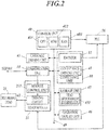
- FIG. 2 is a block diagram showing the functional configuration of the inkjet recording apparatus 1 in the embodiment.
- the inkjet recording apparatus 1 includes a control unit 40, an encoder 11 and a conveyance driving unit 41 of the conveyance unit 10, a driving circuit 42 and a module control unit 211 (communication unit, switching control unit) of the head module 21, a carriage driving unit 43, a communication unit 44, a storage unit 45, an operation display unit 46, a bus 49, a PLC 56 (Programmable Logic Controller) (signal output unit) and the like.
- the control unit 40 integrally controls the operation of the inkjet recording apparatus 1, and performs control operation of causing each component such as the head modules 21 to perform various operations (based on the contents of recording operation).
- the control unit 40 includes a CPU 401 (Central Processing Unit), a ROM 402 (Read Only Memory), a RAM 403 (Random Access Memory) and the like, and the CPU 401 performs various types of arithmetic processing in the RAM 403 as a working memory space.
- the ROM 402 stores initial setting data, various types of control programs, and the like. The CPU 401 reads them as needed, loads them in the RAM 403 and uses the data and executes the programs.
- the conveyance driving unit 41 has a conveyance member of the conveyance unit 10, for example, a motor which moves the endless belt and the like, and moves the belt at a desired speed.
- the encoder 11 is attached to the rotation shaft of this motor, and outputs a pulse signal each time the belt moves for a predetermined movement amount.
- the pulse signal is used for identifying the movement speed, the position and the like of the belt.
- the driving circuit 42 and the module control unit 211 are provided to each of the head modules 21.
- the module control unit 211 transmits/receives a signal to and from the control unit 40 via the communication unit 44.
- the driving circuit 42 performs the driving operation for ink ejection from each recording head 23 on the basis of image data of the recording target in each head module 21.
- each of the recording heads 23 has a configuration of deforming the wall surface of the ink chamber connecting to the nozzle, thereby changing the pressure of ink in the ink chamber and ejecting ink from the nozzle.
- the driving circuit 42 performs output operation of a voltage waveform so as to apply the voltage in a predetermined pattern (voltage waveform) to the piezoelectric element provided along the wall surface of the ink chamber.
- the piezoelectric element deforms according to the voltage waveform, and the wall surface of the ink chamber deforms according to this deformation.
- the module control unit 211 controls the operation of the driving circuit 42 in each of the head modules 21.
- the module control unit 211 receives control data corresponding to the image of the recording target from the control unit 40 and outputs the data to the driving circuit 42 at an appropriate timing.
- the module control unit 211 performs switching control of an after-mentioned switching unit 2121 (see FIG. 4 ) and transmission/reception of information with the control unit 40 for specification of the position of the head module 21.
- module control unit 211 a microcomputer having a CPU, a RAM and a storage unit is used.
- the carriage driving unit 43 moves the carriage 22 of each of the image recording units 20, and moves the recording heads 23 attached to the carriage 22 together.
- the carriage driving unit 43 performs the operation of moving back the recording heads 23 (head modules 21) from the position facing the conveyance surface in a case where adjustment of the head module 21 or the recording heads 23 is performed, or a trouble occurs for cleaning or conveyance of the recording medium, and the like.
- the communication unit 44 performs communication with a computer such as an external data server and a printer server through a network cable (LAN cable or the like).
- the control unit 40 obtains a recording instruction of an image, image data targeted by the recording, setting information regarding the recording operation and the like through the communication unit 44, and outputs status information of the image recording operation and the like.
- the communication unit 44 can communicate with the module control unit 211 of each of the head modules 21 which is connected to the network through hubs 51 to 55 (see FIG. 3 ) as mentioned later.
- the control unit 40 outputs the driving control signal of the head module 21, image recording data and the like (recording control signal) for image recording through the communication unit 44.
- the communication path for communication with an external computer and the communication path for communication with the head module 21 may be provided independently.
- the storage unit 45 stores image data processed for image recording operation and the like.
- the storage unit 45 for example, a DRAM used for temporary storage, a nonvolatile memory or the like is used.
- the storage unit 45 stores head arrangement information 451 regarding actual arrangement order of the plurality of head modules 21. When the control signal for image recording operation is distributed and output to each of the head modules 21, the head arrangement information 451 is loaded in the RAM 403 to be used by the CPU 401 as needed.
- the operation display unit 46 receives user's input operation to output the operation signal to the control unit 40, and displays the menu screen regarding received contents and the status display screen regarding the image recording operation and the like.
- the operation display unit 46 for example, a liquid display screen or the like on which a touch panel is overlaid is used.
- the operation display unit 46 may include a push button switch, an LED lamp or the like.
- the bus 49 is a communication path connecting the control unit 40 with each component.
- the PLC 56 (Programmable Logic Controller) outputs the control signal to each of the head modules 21.
- the PLC 56 has a microcomputer, for example, directly connected to the control unit 40 and the encoder 11, and performs the signal output operation based on the control signal from the control unit 40.
- FIG. 3 is a schematic view for explaining the signal wiring to each of the head modules 21.
- the module control units 211 (see FIG. 4 ) in the respective head modules 21 are connected in parallel through the network to the control unit 40 which controls the image recording via the hubs 51 to 55 through network cables 61 such as LAN cables.
- the head modules 21 are specified by setting respective IP addresses, and can communicate with the control unit 40 individually and in parallel.
- the control unit 40 transmits the recording control signal for ink ejection from each nozzle corresponding to image data to each of the head modules 21 through this network connection.
- the hubs 51 to 55 and the network cables 61 form a first signal path.
- the control unit 40 is directly connected with the PLC 56 as mentioned above, and a control signal is output to the PLC 56 from the control unit 40.
- the PLC 56 outputs the signal to the image recording units 20Y, 20M, 20C and 20K by chain cables 62 (second signal path) through the signal distributor 57.
- each of the chain cables 62 connects a plurality of head modules 21 (driving units) to each other in series in the order which is determined according to the arrangement of the recording heads 23 on the carriage 22, and can transmit the signal to all the head modules 21 in the order.
- a termination unit 58 (terminator) is provided to the end on the output side (downstream side) of the head module 21 which is lowermost in the order, and termination processing is performed to prevent problems such as reflection of the signal.
- the PLC 56 in the embodiment outputs each of three types of signals which are a print enable signal (predetermined control signal regarding whether or not to perform the recording operation), an encoder signal and a head position search signal by a high voltage signal VH or a low voltage signal VL.
- the chain cables 62 transmit these three types of signals by respective independent signal lines (that is, the signal line of head position search signal is along the signal line of the print enable signal).
- the encoder signal input from the encoder 11 of the conveyance unit 10 is input to the PLC 56.
- the encoder signal is a signal which is output according to the conveyance amount (movement distance) of the recording medium P by the conveyance unit 10, and the signal is output each time the motor moving the conveyance belt rotates by a predetermined rotation angle, for example.
- the signal distributer 57 can output a predetermined signal from an end (input end) of the chain cable 62 corresponding to the head module 21 which is the uppermost in the above-mentioned order (that is, head) in any of the image recording units 20 of C, M, Y and K colors selectively.
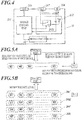
- FIG. 4 is a view for explaining the signal wiring in the head module 21.
- the head module 21 the above-mentioned module control unit 211, the FPGA 212 (Field-Programmable Gate Array) and the driving circuit 42 are provided.
- the head module 21 also includes a communication connection terminal 215, an input terminal 216 and an output terminal 217.
- the network cables 61 connected to the hubs 52 to 55 are connected to module control units 211 through communication connection terminals 215, and transmit signals which are transmitted and received by the module control units 211.
- Each of the module control units 211 includes a CPU (Central Processing Unit), a RAM (Random Access Memory) and the like, and performs, at appropriate timings, output to the driving circuit 42 which applies voltage to a load which determines whether or not to eject ink from each nozzle, that is, the piezoelectric element for deforming the ink chamber connected to the nozzle and generating pressure change of ink inside the ink chamber, or the like on the basis of the input driving data.
- a CPU Central Processing Unit
- RAM Random Access Memory
- the FPGA 212 outputs the print enable signal determining whether or not to operate the driving circuit 42 and the encoder signal to the driving circuit through the chain cable 62 from the PLC 56. Such a signal is input to the input terminal 216, and then branched before input to the FPGA 212. The branched signal is output from the output terminal 217 directly, and transmitted to the head module 21 (or termination unit 58 when the signal is output from the output terminal 217 of the head module 21 which is lowermost in the order, the same applies hereinafter) which is immediately below the head module 21 in the arrangement order among the plurality of head modules 21 which are connected in series.
- the chain cable 62 also transmits an after-mentioned head position search signal.
- the head position search signal is input to the FPGA 212 and branched.
- One of the branched signals is input to the switching unit 2121, and the other is input to the module control unit 211.
- the switching unit 2121 includes a switching element for example, a MOSFET (CMOS) or the like, which switches the connection (performs switching operation) according to the control signal from the module control unit 211.
- the switching unit 2121 switches whether or not to output the head position search signal input from the input terminal 216 (input end side of the chain cable 62) to the output terminal 217 (downstream side of the chain cable 62).
- CMOS MOSFET
- the switching unit 2121 outputs, without change, the head position search signal input from the input terminal 216 or interrupts the head position search signal and outputs the input voltage from a constant voltage source Vcc, which supplies the voltage equal to the above-mentioned high voltage signal VH, to the output terminal 217.
- control unit 40 in order to output image data (driving data) individually to each of the head modules 21 from the control unit 40, the control unit 40 needs to recognize the relative positional relationship between the head modules 21, that is, the arrangement order and the color of ink ejected by the recording heads 23 which are operated by each of the head modules 21.
- the relative positional relationship between heads is narrowed down by the control unit 40 obtaining information on the signal level of the head position search signal which was input from each of the module control units 211 in a state in which the control unit 40 causes the PLC 56 to output the head position search signal.
- FIGS. 5A, 5B , 6A and 6B are views for explaining the position specification operation of head module 21.
- the control unit 40 causes all the module control units 211 to output, without change, the head position search signal, which was input from the input terminal 216, to the downstream side from the output terminal 217 by the switching unit 2121, and respond the voltage level (information regarding input status) of the input head position search signal.
- the control unit 40 specifies the ink color ejected by the image recording unit 20 to which the head module 21 indicated by each IP address (last three digits are displayed in the embodiment) belongs.
- the control unit 40 causes the PLC 56 to output the low voltage signal VL (first control signal, predetermined constant voltage signal) as the head position search signal to each of the image recording units 20, the control unit 40 outputs a control signal to the module control unit 211 of any one head module 21 among the head modules 21 belonging to each of the image recording units 20 to change the switching state by the switching unit 2121 and output the voltage (that is, high voltage signal VH) of the constant voltage source Vcc instead of the input low voltage signal VL. Then, the control unit 40 transmits a request to notify the voltage level of input head position search signal (information regarding input status) to each of the module control units 211.
- VL first control signal, predetermined constant voltage signal
- the voltage level of the head position search signal notified from each of the module control units 211 is the low voltage signal VL as for the head module 21 which caused the above-mentioned switching unit 2121 to perform the switching operation and the head module(s) 21 on the upstream side (input end side) of the head module 21, and the voltage level of the head position search signal is the high voltage signal VH (second control signal, constant voltage signal of a voltage different from the first control signal) as for the head module(s) 21 on the downstream side (termination unit 58 side) of the head module 21 which caused the switching unit 2121 to perform the switching operation.
- VH second control signal, constant voltage signal of a voltage different from the first control signal
- the head modules 21 can be divided into two groups of the upstream side groups 20Ca, 20Ma, 20Ya and 20Ka and the downstream side groups 20Cb, 20Mb, 20Yb and 20Kb by the arrangement order in each of the image recording units 20.
- the arrangement position of the head module 21 is identified uniquely.
- the arrangement order of all the head modules 21 are finally determined by repeating the similar operation for each group classified in such a way.
- FIG. 7 is a flowchart showing a control procedure by the control unit 40 of the head position specification processing executed by the inkjet recording apparatus 1 in the first embodiment.
- the head position specification processing is activated and executed by the user at the time of assembly inspection of the inkjet recording apparatus 1, installing, replacement of the head module 21 and the like.
- control unit 40 invokes and executes image recording unit specification processing (step S101). Then, the control unit 40 invokes and executes head arrangement order specification processing (step S102).
- control unit 40 On the basis of the specified head position information, the control unit 40 stores the relative positional information of each of the head modules 21 in association with specification information of the module control unit 211 by the control unit 40 such as the IP address (step S103). The control unit 40 ends the head position specification processing.
- FIG. 8 is a flowchart showing a control procedure by the control unit 40 of the image recording unit specification processing invoked in the head position specification processing.
- the control unit 40 causes the PLC 56 to output a high voltage signal VH as the head position search signal through the chain cable 62 to the image recording unit 20C which ejects ink of C color, and causes the PLC 56 to output a low voltage signal VL as the head position search signal through the chain cables 62 to the image recording units 20M, 20Y and 20K which eject ink of the other colors (step S301).
- the control unit 40 requests all the module control units 211 to provide the voltage level information (that is, information regarding the input status of the head position search signal (control signal)) of the head position search signal (step S302).
- the control unit 40 obtains the voltage level information which was output from each of the module control units 211, and identifies the IP addresses of the head modules 21 to which the high voltage signal VH was input, that is, the head modules 21 belonging to the image recording unit 20C (step S303).
- the control unit 40 causes the PLC 56 to output the high voltage signal VH as the head position search signal through the chain cable 62 to the image recording unit 20M which ejects ink of M color, and causes the PLC 56 to output the low voltage signal VL as the head position search signal through the chain cables 62 to the image recording units 20C, 20Y and 20K which eject ink of the other colors (step S304).
- the control unit 40 requests all the module control units 211 to provide the voltage level information of the head position search signal (step S305).
- the control unit 40 obtains the voltage level information which was output from each of the module control units 211, and identifies the IP addresses of the head modules 21 to which the high voltage signal VH was input, that is, the head modules 21 belonging to the image recording unit 20M (step S306).
- the control unit 40 causes the PLC 56 to output the high voltage signal VH as the head position search signal through the chain cable 62 to the image recording unit 20Y which ejects ink of Y color, and causes the PLC 56 to output the low voltage signal VL as the head position search signal through the chain cables 62 to the image recording units 20C, 20M and 20K which eject ink of the other colors (step S307).
- the control unit 40 requests all the module control units 211 to provide the voltage level information of the head position search signal (step S308).
- the control unit 40 obtains the voltage level information which was output from each of the module control units 211, and identifies the IP addresses of the head modules 21 to which the high voltage signal VH was input, that is, the head modules 21 belonging to the image recording unit 20Y (step S309).
- the control unit 40 causes the PLC 56 to output the high voltage signal VH as the head position search signal through the chain cable 62 to the image recording unit 20K which ejects ink of K color, and causes the PLC 56 to output the low voltage signal VL as the head position search signal through the chain cables 62 to the image recording units 20C, 20M and 20Y which eject ink of the other colors (step S310).
- the control unit 40 requests all the module control units 211 to provide the voltage level information of the head position search signal (step S311).
- the control unit 40 obtains the voltage level information which was output from each of the module control units 211, and identifies the IP addresses of the head modules 21 to which the high voltage signal VH was input, that is, the head modules 21 belonging to the image recording unit 20K (step S312).
- control unit 40 ends the image recording unit specification processing, and returns the processing to the head position specification processing.
- steps S310 to S312 may be omitted and the control unit 40 may simply identify, among the head modules 21, the remaining head modules 21 which are not identified as belonging to any of the image recording units 20C, 20M and 20Y in each processing of steps S303, S306 and S309 as the head modules 21 belonging to the image recording unit 20K.
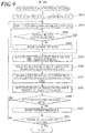
- FIG. 9 is a flowchart showing a control procedure by the control unit 40 of the head arrangement order specification processing invoked in the head position specification processing.
- Each process of the head arrangement order specification processing forms an identification step of the present invention.
- the control unit 40 When the head arrangement order specification processing is invoked, the control unit 40 outputs a control signal to the PLC 56 to output a low voltage signal VL as the head position search signal through the chain cables 62 to all the image recording units 20 (step S501).
- the control unit 40 selects one of the head modules 21 belonging to each of the image recording units 20 (step S502).
- the control unit 40 determines whether or not the selected head modules 21 include a head module 21 which has the arrangement order (position) already identified (step S503). If it is determined that the selected head modules 21 include a head module 21 which has the arrangement order already identified (step S503; YES), the control unit 40 changes the head module 21 to be selected from the identified head module 21 (step S504), and returns the processing to step S503.
- the control unit 40 If it is determined that the selected head modules 21 do not include a head module 21 which has the arrangement order already identified (step S503; NO), the control unit 40 outputs a switching operation instruction of switching unit 2121 to the module control unit 211 of each of the selected head modules 21 to change the switching state, and causes each of the module control units 211 to output a high voltage signal VH (output voltage of constant voltage source Vcc) from the output terminal 217 instead of the input head position search signal (step S505). The control unit 40 requests all the head modules 21 to provide the voltage level information of the input head position search signal (step S506).
- the control unit 40 obtains the voltage level information from the module control unit 211 of each of the head modules 21, and divides, according to high/low of the voltage level, the group including the selected head modules 21 (for the first time, a single group including all the head modules 21 in each of the image recording units 20) (step S507).
- the control unit 40 outputs a reset instruction of the switching operation of switching unit 2121 to the module control unit 211 of each of the selected head modules 21 to return the switching state, leading to a state of outputting the input head position search signal without change from the output terminal 217 (state of making the head position search signal pass through) (step S508).
- the control unit 40 determines, for the divided groups, whether or not there is generated a group including only one head module 21 (step S509). If it is determined that such a group is generated (step S509; YES), the control unit 40 identifies the arrangement order of the head module 21 of the group (step S510). The control unit 40 determines whether or not the positions (arrangement order) of all the head modules 21 are identified (step S511). If it is determined that the positions of all the head modules 21 are not identified (step S511; NO), the processing of the control unit 40 returns to step S502. If it is determined that the positions of all the head modules 21 are identified (step S511; YES), the control unit 40 ends the head arrangement order specification processing and returns the processing to the head position specification processing.
- step S509 if it is determined that the group including only one head module 21 is not newly generated (step S509; NO), the processing of the control unit 40 returns to step S502.
- step S509 if the group including two head modules 21 is divided into two, both of the positions (arrangement order) of the two head modules 21 are identified.
- the IP address is dynamically assigned to each of the head modules 21 by using DHCP or the like, it is preferable that various settings such as a lease period are maintained so that the IP address is not changed when the inkjet recording apparatus 1 is activated again after the period during which the power supply to the inkjet recording apparatus 1 is stopped.
- the MAC address (physical address) and the arrangement of each of the head modules 21 may be stored so as to be associated with each other by obtaining an ARP table or the like, and when the apparatus is activated again, the association between the IP address and the arrangement of the head module 21 may be updated with only the operation of the control unit 40 by updating the ARP table.
- the arrangement information of the identified head module 21 may be transmitted to each of the head modules 21 from the control unit 40 and stored, and when the apparatus is activated again, the information may be obtained in association with the IP address from each of the head modules 21.
- an inkjet recording apparatus 1 in the first embodiment includes: seven head modules 21 that respectively drive a predetermined number (seven in the embodiment) of sets of recording heads 23 each set of which includes a prescribed number of recording heads 23 and performs recording operation, the predetermined number being two or more; a control unit 40 which performs control operation of seven head modules 21 on the basis of the contents of the recording operation; network cables 61 and hubs 51 to 55 as a first signal path connecting the control unit 40 and the seven head modules 21 in parallel; and chain cable 62 as a second signal path through which a control signal is input to the head module 21 which is uppermost (on the side closest to the PLC 56) in the order determined according to the arrangement of the seven sets of recording heads 23 among the seven head modules 21 from the input end connected to the signal distributer 57, and which connects the seven head modules 21 to each other so that the control signal can be transmitted in the order to the head module 21 which is lowermost (on the side closest to the termination unit 58) in the order at least.
- Each of at least six head modules 21 (upstream side driving unit) (all the seven head modules 21 in the embodiment) from the uppermost head module 21 to the head module 21 connected immediately above the lowermost head module 21 among the seven head modules 21 has a switching unit 2121 which switches whether or not to output the control signal transmitted through the second signal path from the PLC 56 side (input terminal 216) to the downstream side (output terminal 217) which is on the opposite side (the termination unit 58 side) to the PLC 56 side.
- the control unit 40 obtains, through the first signal path, information regarding the input status (that is, whether or not the low voltage signal VL was input) of the control signal to each of at least six head modules 21 (all the seven head modules 21 in a case where the six upstream side driving units are not identified in advance as in the embodiment) other than the lowermost head module 21 in the arrangement order by the chain cable 62 corresponding to the switching state of the switching unit 2121 in each of the seven head modules 21, identifies the arrangement of the seven sets of recording heads 23, and outputs the recording control signal based on the content of the recording operation corresponding to the arrangement of the recording heads 23 to each of the seven head modules 21 through the first signal path.
- the network cables 61 and chain cable 62 two-dimensionally connected to the head modules 21 and obtaining information on the input control signal corresponding to the switching state of the switching unit 2121 of each of the head modules 21, the actual arrangement positions of the recording heads 23 and each corresponding head module 21 are specified even in a case where the actual arrangement of each (set of) recording heads 23 is not known and an arbitrary identification number is assigned to each head module 21 corresponding to the recording heads 23.
- each of the head modules 21 does not need to perform the setting processing operation of the identification number or the identification mark considering the arrangement position, and, by only the simple switching operation, the control unit 40 which requires the information on the arrangement order can perform processing and management regarding the setting of the arrangement order all together at the time of transmitting image data. Accordingly, in this inkjet recording apparatus 1, it is possible to avoid setting management errors without requiring addition or change of a large configuration, and obtain the arrangement information of the recording heads 23 and the head module 21 corresponding to the recording heads 23 easily and appropriately, perform setting regarding control of the image recording operation and use the information for the image recording operation.
- the control unit 40 controls the setting of the switching state by the switching unit 2121, and obtains the information regarding the input status of the control signal through the first signal path (network connection) for each setting pattern of the switching state. Accordingly, the control unit 40 intensively sets an appropriate switching pattern of the switching unit 2121 and obtains the arrangement information of the head module 21 efficiently.
- the switching unit 2121 In a case where the switching state of the switching unit 2121 changes and the control signal (low voltage signal VL) input from the PLC 56 side (input terminal 216) is not output to the downstream side (output terminal 217), the switching unit 2121 outputs the voltage signal from the constant voltage source Vcc to the downstream side. Accordingly, the detection signal (voltage level) on the downstream side of the switching unit 2121 is determined appropriately, and can be more clearly and surely distinguished from the signal on the upstream side (PLC 56 side).
- the control unit 40 causes each of the switching units 2121 to perform switching in order (the order mentioned here is not fixed but determined as needed according to the state of group division as mentioned above) in a state in which the low voltage signal VL different from the high voltage signal VH output by the constant voltage source Vcc determined in advance is input from the input end (PLC 56 side) of the chain cable 62 of the second signal path.
- the control unit 40 then obtains the type of the control signal which was input to each of the seven head modules 21 as the information regarding the input status from each of the seven head modules 21 through the first signal path, and thereby identifies the arrangement of the seven sets of recording heads 23.
- the arrangement order of each of the head modules 21 (that is, arrangement positions of the recording heads 23) is specified by only the simple switching operation of switching the input voltage signal and the voltage signal from the constant voltage source Vcc which supplies the voltage different from the input voltage signal.
- Vcc constant voltage source
- the first control signal input from the PLC 56 side is a predetermined constant voltage signal (low voltage signal VL), and the second control signal output to the downstream side instead of the first control signal by the switching unit 2121 is a constant voltage signal (high voltage signal VH) of the voltage different from the first control signal. Since such a signal makes it possible to identify the signal type easily only by the determination of signal level, the processing such as reading determination of the signal waveform pattern is not necessary, and especially, it is possible to more simplify the contents of processing operation in the head module 21.
- Each of the seven head modules 21 has a switching unit 2121.
- the head module 21 of a same configuration it is possible to provide the head module 21 at an arbitrary arrangement order position with respect to the control unit 40 and the recording heads 23 as needed, and reduce the cost and trouble for manufacturing and replacement work (especially, in a case where the head module 21 is replaced together with the recording heads 23). Even by such a same configuration, it is possible to surely identify the arrangement order by the chain cable 62 of each of the head modules 21 in the inkjet recording apparatus 1 in the embodiment.
- the chain cable 62 of the second signal path is provided along the signal line used for transmission of the print enable signal regarding whether or not to perform the recording operation.
- the inkjet recording apparatus 1 includes a PLC 56 which inputs a control signal such as a low voltage signal VL through the signal distributer 57 to the input end of the chain cable 62 of the second signal path.
- the PLC 56 determines the control signal to be input to the chain cable 62 on the basis of the control by the control unit 40.
- the low voltage signal VL and the like can be output as the head position search signal by using the PLC 56 (programmable logic controller), it is possible to identify the arrangement of the recording heads 23 and the arrangement order of the head module 21 corresponding to the recording heads 23 without complicating the configuration and the processing by using (multiple uses) the PLC 56 which is provided for the output control of important signals such as a print enable signal.
- the PLC 56 programmable logic controller
- the end on the downstream side of the second signal path (chain cable 62) is subjected to the termination processing by the termination unit 58.
- the control unit 40 since information is directly obtained from each of the head modules 21 through the first signal path (network cables 61 and hubs 51 to 55), the control unit 40 does not need to perform confirmation and processing of the signal from the chain cable 62, and especially does not need to perform processing of confirming which head module 21 performed the data changing processing or the like from the data that is input in series.
- the first signal path has hubs 51 to 55 and network cables 61 which connect the control unit 40 and the seven head modules 21 via the hubs 51 to 55, and each of the seven head modules 21 has a module control unit 211 which identifies the head module 21 and performs communication.
- the image data, command data and the like which are output separately to each of the head modules 21 from the control unit 40 side can be distributed and transmitted to each of the head modules 21 at a high speed efficiently by a normal network connection, it is possible to increase the speed of the image recording operation easily.
- the IP address does not represent the actual arrangement positions of the recording heads 23 in such a network connection, by identifying the arrangement order of the head module 21 as mentioned above, it is possible to easily associate the IP address with the information on the arrangement position of the recording heads 23 and enable appropriate image data transmission.
- the inkjet recording apparatus 1 includes four rows of arrangements of seven sets of recording heads 23 according to the respective colors of C, M, Y and K.
- the chain cables 62 of the second signal path are provided to the respective arrangements of four rows, and can selectively output the control signal for each arrangement.
- the control unit 40 obtains information regarding the input status (type) of the control signal input to the head module 21 for each arrangement of four rows from the head module 21 through the first signal path, and thereby determines the arrangement (that is, the color of ejected ink) to which the recording heads 23 corresponding to the head module 21 belong.
- this inkjet recording apparatus 1 it is possible to easily and separately identify the head modules 21 for the image recording unit corresponding to ink of each of the plurality of colors. Accordingly, after identifying the image recording unit 20, the arrangement order of the head module 21 (arrangement positions of recording heads 23) belonging to each of the image recording units 20 can be easily identified as mentioned above.
- the inkjet recording apparatus 1 in the embodiment includes each configuration (which includes a control unit 40, a head module 21, hubs 51 to 55, network cables 61 and chain cable 62, and may include the PLC 56, the termination unit 58 and the like) for the above-mentioned image recording control as the image recording control apparatus, and seven sets of recording heads 23.
- each configuration which includes a control unit 40, a head module 21, hubs 51 to 55, network cables 61 and chain cable 62, and may include the PLC 56, the termination unit 58 and the like
- the image recording control apparatus and seven sets of recording heads 23.
- FIG. 10 is a schematic view for explaining the signal wiring to each of the head modules 21 in the inkjet recording apparatus 1 in the second embodiment.
- control signal is not output from the head modules 21 which are the lowermost head modules in the connection orders among the head modules 21 connected by the chain cables 62, that is, located on the most downstream side, and termination processing is performed by the termination units 218 included in the respective head modules 21.
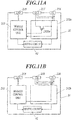
- FIGS. 11A and 11B are views for explaining the signal wiring in the head module 21 of the inkjet recording apparatus 1 in the second embodiment.
- the configuration is different between the head module 21 which is the lowermost head module in the connection order and the other head modules (six head modules) among the head modules 21 connected through the chain cable 62.
- a switching unit 2121a to the FPGA 212a instead of the switching unit 2121 in the FPGA 212 of the head module 21 in the inkjet recording apparatus 1 in the first embodiment.
- the switching unit 2121a simply switches whether or not to output, from the output terminal 217, the control signal input from the input terminal 216 on the basis of the control of the module control unit 211. Accordingly, in a case where the switching element (for example, MOSFET) of the switching unit 2121a is turned off (released), the control signal is not output from the output terminal 217.
- the termination unit 218 is provided instead of the output terminal 217, and the control signal is not output to the downstream side.
- the FPGA212b does not have the switching unit 2121a, the head position search signal input from the input terminal 216 is simply divided into two similarly to the other signals transmitted through the chain cable 62 (print enable signal and encoder signal). One of the divided signals is input to the termination unit 218 and the other is input to the module control unit 211.
- the arrangement of the head module 21, that is, the recording heads 23 is identified by using information regarding whether or not there was input to each head module 21 (presence/absence of input) of the control signal (low voltage signal VL) which was input from the PLC 56 according to the switching state of the switching unit 2121a.
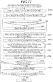
- FIG. 12 is a flowchart showing a control procedure by the control unit 40 of head arrangement order specification processing invoked when the head position specification processing is executed in the inkjet recording apparatus 1 in the embodiment.
- the head arrangement order specification is same as the head arrangement order specification in the first embodiment except for that the processing of step S501 is divided into steps S501a and S501b which are respectively arranged at the head of processing and after processing of step S505.
- the explanation is omitted by providing same reference numerals to same processing contents.
- control unit 40 causes the PLC 56 to output a high voltage signal VH to all the image recording units 20 to initialize the input signal to each of the head modules 21 (step S501a). The processing of the control unit 40 then proceeds to step S502.
- the control unit 40 causes the PLC 56 to output a low voltage signal VL to all the image recording units 20 after changing the switching unit 2121a of the selected head module 21 to the switching state, that is, the turning off (released state) of the switching element in the embodiment in the processing of step S505 (step S501b). The processing of the control unit 40 then proceeds to step S506.
- this head module 21, to which the instruction was input in the processing of step S505 may return an error signal indicating not having the switching unit 2121a to the control unit 40.
- the head module 21 is identified as the head module which is the lowermost in the order for not having the switching unit 2121a (identified as the only one head module 21 in the group on the lower side of the group including the head module 21).
- the control unit 40 may omit the processing of steps S501b to S508.
- the control unit 40 may request each of the head modules 21 to provide information regarding whether or not the head module 21 has the switching unit 2121a in advance, and identify the head module 21 returning the information of not having the switching unit 2121a, that is, the head module 21 which is the lowermost in the arrangement order.
- the lowermost head module 21 may be excluded from the selection target for switching of the switching unit 2121a from first, and may be excluded from the target to request to provide the voltage level information of the head position search signal.
- the switching unit 2121a is a switching element which switches on and off, by using that the downstream side of the switching element in the released state is maintained in a floating state, it is possible to obtain presence/absence of input of the control signal (low voltage sig al VL) to each of the head modules 21 on the basis of the switching state of voltage level after initialization, and obtain the positional relationship (arrangement order) of the head module 21.
- initialization may be performed with a ground voltage or a low voltage signal VL close to the ground voltage and a high voltage signal VH may be output after the selective switching of the switching element so that the position of the head module 21 (recording heads 23) corresponding to the switching element (switching unit 2121a) is obtained.
- the switching unit 2121a in a case where the switching unit 2121a does not output the first control signal (low voltage signal VL) input from the input end side (PLC 56 side, input terminal 216) to the downstream side (output terminal 217), the switching element is released and the control signal is not output to the downstream side of the switching unit 2121a.
- VL low voltage signal
- the control unit 40 causes each of the switching units 2121a to perform switching in order in a state in which the first control signal (low voltage signal VL) is input from the input end (PLC 56), and identifies the arrangement of the seven recording heads 23 by obtaining the presence/absence of input of the first control signal to each of at least the six head modules 21 (upstream side driving units) from the uppermost head module 21 to the head module 21 which is immediately above the lowermost head module 21 in the arrangement order as the information regarding input status from these six (or all of the seven) head modules 21 through the first signal path.
- the first control signal low voltage signal VL
- PLC 56 input end
- the switching unit 2121a may not be provided to the head modules 21 each of which is the lowermost in the arrangement order. In this case, the arrangement order of each of the head modules 21 can be identified similarly. If it is possible to identify in advance that the head module 21 not provided with the switching unit 2121a is the head module 21 which is the lowermost in the arrangement order, the head module 21 can be excluded from the identification processing of the arrangement order by the above-mentioned method, and the processing can be omitted one time.
- the module control unit 211 of the head module 21 not only changes the switching state of the switching unit 2121 at the timing when the instruction is obtained from the control unit 40, but also performs switching of the switching unit 2121 based on the control signal which was input through the chain cable 62.
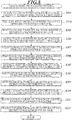
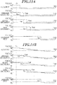
- FIGS. 13A and 13B are views for explaining the change in the switching states of switching unit 2121 and the input/output levels of the signal through the chain cable 62 in the inkjet recording apparatus 1 in the embodiment.
- each of the switching units 2121 when a low voltage signal VL is input as an input signal Vin in a case where the switching state is set (changed) so as to output the supplied voltage from the constant voltage source Vcc, each of the switching units 2121 returns the switching state with delay of a predetermined time, to a state in which the input signal Vin is transmitted and output as the output signal Vout.
- the head modules 21 have different timings (input periods) of switching the voltage level of the output signal Vout to the low voltage signal VL in accordance with the connection order of the head modules 21 through the chain cable 62. Accordingly, the differences of the timings directly indicate the connection orders through the chain cable 62.
- FIG. 14 is a flowchart showing a control procedure by the control unit 40 of the head arrangement order specification processing invoked in the head position specification processing in the inkjet recording apparatus 1 in the embodiment.
- control unit 40 causes the PLC 56 to output the high voltage signal VH to all the image recording units 20 (step S521).
- the control unit 40 outputs a control signal to all the head modules 21 to cause all the switching units 2121 to switch to the output state of the supplied voltage (that is, high voltage signal VH) from the constant voltage source Vcc (step S522).
- the control unit 40 outputs, to all the head modules 21, the instruction to return the switching state of the switching unit 2121 after elapse of the predetermined time from detection of the low voltage signal VL, into a state of outputting the signal input from the input terminal 216 to the output terminal 217 (step S523).
- the module control unit 211 of the head module 21 may hold the setting of operating the switching unit 2121 in such a way from start, or may have a circuit enabling the switching unit 2121 to perform such switching automatically. In this case, the processing of step S523 is omitted.
- the control unit 40 causes the PLC 56 to output a low voltage signal VL to all the image recording units 20 (step S524).
- the control unit 40 requests all the head modules 21 to provide the voltage level information of the head position search signal (step S525).
- the control unit 40 identifies the position (order) of the head module 21 in accordance with the order of switching of the head position search signal to the low voltage signal VL (step S526).
- the control unit 40 determines whether the voltage level of the head position search signal obtained from every head module 21 switched to the low voltage signal VL (step S527). If it is determined that the voltage level was not switched (step S527; NO), the processing of the control unit 40 returns to step S525. If it is determined that the voltage level was switched (step S527; YES), the control unit 40 ends the head arrangement order specification processing, and returns the processing to the head position specification processing.
- step S527 proceeds to NO, the timing to execute the processing of step S525 may be after the elapse of the above-mentioned predetermined time from the processing of previous step S525.
- FIG. 13B is a view for explaining the change in the switching states of switching unit 2121 and the input/output levels of the signal through the chain cable 62 in the modification example.
- the control unit 40 causes the PLC 56 to output the head position search signal changing the voltage value in a step manner each predetermined time.
- the PLC 56 may output signals obtained by pulse width modulation (PWM) between the high voltage signal VH and the low voltage signal VL instead of actually outputting direct current signals (constant voltage signals) of voltage values which are different from each other.
- PWM pulse width modulation
- the minimum required number of steps of the voltage value is the number smaller than the number of head modules 21 by 1.
- the output voltage from the PLC 56 may be simply gradually decreased continuously.
- the switching unit 2121 operates with a delay of predetermined time from detection of the input signal Vin of the voltage other than the high voltage signal VH, and outputs the input signal Vin as the output signal Vout.
- the voltage level average voltage value in a case of PWM control
- the control unit 40 can identify the arrangement order of the head module 21 and the recording heads 23 by obtaining the information regarding the voltage level.
- FIG. 15 is a flowchart showing a control procedure by the control unit 40 of the head arrangement order specification processing for the position specification operation in the modification example.
- the head arrangement order specification processing is same as the head arrangement order specification processing in the third embodiment except for that the processing of steps S525 and S527 is omitted and the processing of steps S523, S524 and s526 are replaced with steps S523a, S524a and S526a, and the explanation thereof is omitted by providing same reference numerals to the same processing contents.
- the control unit 40 After the head arrangement order specification processing is invoked and the processing of steps S521 and S522 are executed in order, the control unit 40 outputs, to all the head modules 21, an instruction to change the switching state of the switching unit 2121 after elapse of a predetermined time from detection of the signal other than the high voltage signal VH (less than the high voltage signal VH in the modification example), into a state of outputting the head position search signal, which was input to the input terminal 216, to the output terminal 217.
- the control unit 40 obtains a voltage value (average voltage) in the predetermined time from detection of the signal other than the high voltage signal VH, and requests output of the voltage level information to the control unit 40 (step S523a).
- the control unit 40 causes the PLC 56 to output the head position search signal decreasing the voltage value in a step manner each above-mentioned predetermined time (step S524a).
- the control unit 40 receives information of the voltage value input from each of the head modules 21, and identifies the arrangement order of the head module 21 and the recording heads 23 in accordance with the order of the voltage value (decreasing order in the modification example) (step S526a).
- the control unit 40 ends the head arrangement order specification processing and returns the processing to the head position specification processing.
- the switching unit 2121 changes the state of switching after a predetermined time elapsed by the control of the module control unit 211.
- the processing can be simplified. Since such processing does not need to cause each of the head modules 21 to hold the arrangement order itself or perform complicated processing, it is not necessary to greatly complicate the configuration of the head module 21 or the contents of the processing operation.
- the control unit 40 obtains the data of the input timing (information corresponding to the input period) of the first control signal as the information regarding the input status from each of the head modules 21.
- each of the head modules 21 (module control units 211) outputs the signal indicating that the first control signal was detected to the control unit 40 at the detection timing of the first control signal (or request timing from the control unit 40 immediately after the detection timing), and changes the switching state of the switching unit 2121 after elapse of the predetermined time from the detection timing.
- the control unit 40 it is possible to easily and surely identify the arrangement order of each of the head modules 21 by the control unit 40 without requiring the complicated processing in the head module 21.
- the head module 21 having the switching unit 2121 has a module control unit 211 which causes the switching unit 2121 to change the switching state on the basis of the input control signal.
- a module control unit 211 which causes the switching unit 2121 to change the switching state on the basis of the input control signal.
- the first control signal is a signal changing the signal contents each predetermined time
- the control unit 40 identifies the arrangement of the seven recording heads 23 by obtaining, as the information regarding the input status, the contents of the first control signal until the elapse of the predetermined time from input of the first control signal, from each of the head modules 21 through the first signal path.
- the inkjet recording apparatus 1 it is sufficient that the voltage level in the first period when the first control signal was detected is obtained from each of the head modules 21 one time.
- the inkjet recording apparatus 1 it is possible to surely obtain the information regarding the arrangement order of the head module 21 while more decreasing the processing of the control unit 40.
- the contents of signal to change there is only performed changing the duty ratio by the PWM control between the low voltage signal VL and the high voltage signal VH, and thereby it is possible to obtain necessary information by easy processing without applying a large load.
- the USB cable may be used to connect each of the head modules 21 to the control unit 40 directly or through a USB hub or the like.
- the module control unit 211 of the head module 21 which caused the switching operation is classified to a set in which the head position search signal is a low voltage signal VL, and the processing is repeated until all the head modules 21, including the head module 21, are divided into separate groups each of which has a single component.
- This head module 21 is on the most downstream side in the set in which the head position search signal is the low voltage signal VL. Accordingly, the arrangement order of the head module 21 which caused the switching operation may be determined in order by counting the number of the other head modules 21 to which the low voltage signal VL was input and the number of head modules 21 to which the high voltage signal VH was input.
- the print enable signal, the encoder signal and the head position search signal are transmitted through respective independent signal lines.
- the signal line transmitting the head position search signal the signal line transmitting the print enable signal or the encoder signal may be used and the operation may be performed by switching which signal is to be supplied from the PLC 56 by control of the control unit 40 or the like.
- the switching unit 2121 performs the switching operation, the switching is performed so that the high voltage signal VH is output from the constant voltage source Vcc.
- the input signal may be inverted between the high voltage and the low voltage by providing an inverter or the like to the switching side.
- the switching unit 2121 may not be provided to the last head module 21 connected in order by the chain cable 62. That is, the switching unit 2121 is provided to the head modules 21 from the head module 21 at the head in the connection order (PLC 56 side) to the head module 21 which is connected immediately ahead of the last (termination unit 58) head module 21 among the head modules 21 connected by the chain cable 62.
- the switching unit 2121 has a hardware configuration having the switching element.
- the module control unit 211 may determine whether or not to output (invert to other signal), to downstream side, the head position search signal which was input according to the control signal from the control unit 40 so that, when the head position search signal is input, whether to output the head position search signal is switched (the inverted head position search signal or the head position search signal which is not changed is output) on the basis of the determination.
- the head position search signal is not limited to the signal of a constant voltage shown in the embodiments.
- the head position search signal may be a predetermined period signal or a signal differentiating the phase such as sine wave or pulse wave or a signal inverting the positive/negative of the voltage.
- the alternating current component attenuates promptly on the downstream side by the termination unit 58 even if the switching unit 2121 merely switches whether or not to output the head position search signal to the downstream side as in the inkjet recording apparatus 1 in the second embodiment.
- each of the head modules 21 returns the switching state of the switching unit 2121 by counting the predetermined delay time spontaneously on the basis of the control signal input.
- each of the head modules 21 may not count the delay time, and the switching state of the switching unit 2121 may be returned in a case where the output voltage level is a low voltage signal VL at the same time as or immediately after output of the voltage level information (before the next request by the control unit 40 to provide the voltage level information) when the voltage level information is requested at a predetermined time interval by the control unit 40.
- the switching unit 2121 may not switch to the output of the voltage signal supplied from the constant voltage source Vcc, and the output (transmission) of the voltage signal input from the input terminal 216 may be switched on/off.
- the head module 21 which is not provided with the switching unit 2121 may be used as the head module 21 which is the last in the order.
- the head arrangement order specification processing shown in FIGS. 14 and 15 it is possible to obtain the arrangement order of all the head modules 21.
- the head module 21 may be excluded from the output target of each instruction in the processing of steps S523 and S523a, request in the processing of step S525, and the like.
- the head position search signal is output from the PLC 56.
- the control unit 40 may control other voltage generation circuits or the like to output the head position search signal.
- the termination processing is performed by providing the termination unit 58 to the end on the downstream side of the chain cable 62.
- the end on the downstream side of the chain cable 62 may be connected to the control unit 40 to input the head position search signal and the like to the control unit 40.
- the termination unit 58 may not be provided to the end on the downstream side of the chain cable 62, and the insulating member or the like may be simply used into a released state.
- the head modules 21 corresponding to respective recording heads 23 which eject ink of four colors of C, M, Y and K are connected through respective different chain cables 62.
- all the head modules 21 may be connected through the chain cable 62 in a line in a case where all the recording head 23 are attached to a same carriage 22, for example.
- the inkjet recording apparatus arranging a plurality of nozzles which eject ink is described as an example.
- the present invention can also be applied to other image recording apparatuses such as an LED printer which arranges a plurality of LED light emitting elements, as long as the apparatus has a similar configuration.
- the present invention can be used for an image recording control apparatus, an image recording apparatus and a method for identifying arrangement of recording operation units.
Landscapes
- Ink Jet (AREA)
- Accessory Devices And Overall Control Thereof (AREA)
- Particle Formation And Scattering Control In Inkjet Printers (AREA)
Abstract
Description
- The present invention relates to an image recording control apparatus, an image recording apparatus, and a method for identifying arrangement of recording operation units.
- There have been conventionally image recording apparatuses which each arrange a plurality of recording elements and record an image on recording mediums by controlling the image recording operation of each of the recording elements. Such image recording apparatuses can improve the recording speed by increasing the number of recording elements and enabling the image recording operation for a wider range at once. For such image recording apparatuses, there is a technique of decreasing the trouble and cost caused by the generation of defects of recording elements and improving the efficiency by arranging a plurality of recording heads in each of which a predetermined number of recording elements are arranged, and enabling separate adjustment and replacement of each of the recording heads.
- In order to record images at high speed in an image recording apparatus which arranges, in such a way, a plurality of recording heads or a plurality of recording operation units each of which is a unit of one or a plurality of recording heads, it is necessary to input image data, that is, a drive signal of each recording head to each of the recording operation units from a print server or the like at high speed.
Patent document 1 discloses a technique of providing a bypass path of data to a plurality of drive substrates connected in series, inputting serial data including the drive signal of each drive substrate from a control substrate simultaneously in a parallel manner, and extracting the data part corresponding to the identification number of each drive substrate in the drive substrate to perform the drive operation. - On the other hand, a synchronization signal, a predetermined drive voltage, a ground voltage and the like, for which a same signal (voltage) is supplied to each recording operation unit and drive substrate, are transmitted from a single supply source to each recording operation unit and drive substrate separately.
- Patent Document 1: Japanese Patent Application Laid Open Publication No.
2008-12909 - However, in order to extract image data for an appropriate portion corresponding to the arrangement of each recording operation unit in a plurality of recording operation units, it is necessary to have information regarding the relative positional relationship between each recording operation unit and the other recording operation units. This relative positional information such as the arrangement order of recording operation units and relative coordinates is obtained by using a DIP switch or the like for a user of the image recording apparatus to perform manual setting, and acquiring, with a print server, the signal corresponding to the setting of the DIP switch from the driver or the like which drives each recording operation unit. Since such setting bothers the user, there is a problem that error easily occurs especially in a case where a large number of recording operation units are provided and in a case where the recording operation units are partially replaced.
- An object of the present invention is to provide an image recording control apparatus, an image recording apparatus and a method for identifying the arrangement of recording operation units which can perform setting regarding the operation control of a plurality of recording operation units easily and appropriately without requiring addition or change of a large configuration.
- In order to achieve the above object, the invention described in
claim 1 is an image recording control apparatus, including: a predetermined number of driving units which respectively drive the predetermined number of recording operation units which perform a recording operation by a plurality of recording elements, the predetermined number being two or more; a control unit which performs a control operation of the predetermined number of driving units based on a content of the recording operation; a first signal path which connects the control unit and the predetermined number of driving units in parallel; and a second signal path through which a control signal is input from an input end to the driving unit that is uppermost in an order determined according to arrangement of the predetermined number of recording operation units among the predetermined number of driving units, and which connects the predetermined number of driving units to each other so that the control signal is transmitted in the order to the driving unit that is lowermost in the order, wherein at least an upstream side driving unit from the uppermost driving unit to the driving unit which is connected immediately above the lowermost driving unit among the predetermined number of driving units has a switching unit which switches whether or not to output the control signal transmitted through the second signal path from an input end side to a downstream side opposite to the input end side, the control unit identifies the arrangement of the predetermined number of recording operation units by obtaining, through the first signal path, information regarding an input status of the control signal to at least the upstream side driving unit through the second signal path corresponding to a switching state of the switching unit, and the control unit outputs a recording control signal based on the content of the recording operation corresponding to the arrangement to each of the predetermined number of driving units through the first signal path. - The invention described in claim 2 is the image recording control apparatus described in
claim 1, wherein the control unit sets and controls the switching state by the switching unit, and obtains the information regarding the input status of the control signal through the first signal path for each setting pattern of the switching state. - The invention described in
claim 3 is the image recording control apparatus described inclaim 1 or 2, wherein, when a first control signal input from the input end side is not output to the downstream side, the switching unit outputs a second control signal to the downstream side. - The invention described in
claim 4 is the image recording control apparatus described inclaim 3, wherein the control unit identifies the arrangement of the predetermined number of recording operation units by causing each of the switching unit to perform switching in order in a state in which the first control signal different from the second control signal determined in advance is input from the input end, and obtaining a type of the control signal input to each of at least the upstream side driving unit as the information regarding the input status from at least the upstream side driving unit through the first signal path. - The invention described in
claim 5 is the image recording control apparatus described inclaim - The invention described in claim 6 is the image recording control apparatus described in
claim 1 or 2, wherein, when a first control signal input from the input end side is not output to the downstream side, the switching unit does not output the control signal to the downstream side of the switching unit. - The invention described in claim 7 is the image recording control apparatus described in claim 6, wherein the control unit identifies the arrangement of the predetermined number of recording operation units by causing each of the switching unit to perform switching in order in a state in which the first control signal is input from the input end, and obtaining whether or not the first control signal is input to each of at least the upstream side driving unit as the information regarding the input status from at least the upstream side driving unit through the first signal path.
- The invention described in claim 8 is the image recording control apparatus described in
claim 1, when a first control signal is input from the input end side, the switching unit changes the switching state after a predetermined time elapses. - The invention described in
claim 9 is the image recording control apparatus described in claim 8, wherein the control unit obtains information corresponding to an input period of the first control signal as the information regarding the input status from at least the upstream side driving unit. - The invention described in
claim 10 is the image recording control apparatus described inclaim 8 or 9, wherein the first control signal is a signal which changes a content of the signal each the predetermined time, and the control unit identifies the arrangement of the predetermined number of recording operation units by obtaining the content of the first control signal until elapse of the predetermined time from input of the first control signal as the information regarding the input status from at least the upstream side driving unit through the first signal path. - The invention described in
claim 11 is the image recording control apparatus described in any one of claims 8 to 10, wherein the driving unit having the switching unit has a switching control unit which causes the switching unit to change the switching state based on the input control signal. - The invention described in claim 12 is the image recording control apparatus described in any one of
claims 1 to 11, wherein each of the predetermined number of driving units has the switching unit. - The invention described in claim 13 is the image recording control apparatus described in any one of
claims 1 to 12, wherein the second signal path is provided along a signal line which is used for transmission of a predetermined control signal regarding whether or not to perform the recording operation. - The invention described in claim 14 is the image recording control apparatus described in any one of
claims 1 to 13, including a signal output unit which inputs a control signal to the input end, wherein the signal output unit determines the control signal to be input to the input end based on control of the control unit. - The invention described in claim 15 is the image recording control apparatus described in claim 14, wherein the signal output unit is a programmable logic controller.
- The invention described in claim 16 is the image recording control apparatus described in any one of
claims 1 to 15, wherein the second signal path is subjected to termination processing at an end on the downstream side. - The invention described in claim 17 is the image recording control apparatus described in any one of
claims 1 to 16, wherein the first signal path has a hub and a network cable which connects the control unit and the predetermined number of driving units via the hub, and the predetermined number of driving units have a communication unit which performs communication by identifying each of the driving units. - The invention described in claim 18 is the image recording control apparatus described in any one of
claims 1 to 17, including a plurality of arrangements each of which is the arrangement of the predetermined number of recording operation units, wherein the second signal path is provided to each of the plurality of arrangements, and allows the control signal to be selectively output for each of the plurality of arrangements, and the control unit determines the arrangement to which the recording operation unit corresponding to the driving unit belongs by obtaining, from the driving unit through the first signal path, the information regarding the input status of the control signal which is input to the driving unit for each of the plurality of arrangements. - The invention described in claim 19 is an image recording apparatus, including; the image recording control apparatus according to any one of
claims 1 to 18; and the predetermined number of recording operation units. - The invention described in
claim 20 is a method for identifying arrangement of recording operation units by an image recording control apparatus that includes: a predetermined number of driving units which respectively drive the predetermined number of the recording operation units that are provided in a predetermined arrangement and perform a recording operation corresponding to the arrangement by a plurality of recording elements, the predetermined number being two or more; a control unit which performs a control operation of the predetermined number of driving units based on a content of the recording operation; a first signal path which connects the control unit and the predetermined number of driving units in parallel; and a second signal path through which a control signal is input from an input end to the driving unit that is uppermost in an order corresponding to the arrangement of the predetermined number of recording operation units among the predetermined number of driving units, and which connects the predetermined number of driving units to each other so that the control signal is transmitted in the order to the driving unit that is lowermost in the order, wherein at least an upstream side driving unit from the uppermost driving unit to the driving unit which is connected immediately above the lowermost driving unit among the predetermined number of driving units has a switching unit which switches whether or not to output the control signal transmitted through the second signal path from an input end side to a downstream side opposite to the input end side, the control unit outputs a recording control signal based on the content of the recording operation corresponding to the arrangement to each of the predetermined number of driving units through the first signal path, the method including an identification step of identifying the arrangement of the predetermined number of recording operation units by obtaining, through the first signal path, information regarding an input status of the control signal to at least the upstream side driving unit through the second signal path corresponding to a switching state of the switching unit. - According to the present invention, there is an effect that it is possible to obtain setting regarding the operation control of a plurality of recording operation units easily and appropriately without requiring addition or change of a large configuration.
-
- [
FIG. 1 ] This is an entire perspective view showing an inkjet recording apparatus in an embodiment of the present invention. - [
FIG. 2 ] This is a block diagram showing a functional configuration of the inkjet recording apparatus. - [
FIG. 3 ] This is a schematic view for explaining signal wiring to each head module. - [
FIG. 4 ] This is a view for explaining signal wiring in the head module. - [
FIG. 5A ] This is a view for explaining the specification operation of the position of head module. - [
FIG. 5B ] This is a view for explaining the specification operation of the position of head module. - [
FIG. 6A ] This is a view for explaining the specification operation of the position of head module. - [
FIG. 6B ] This is a view for explaining the specification operation of the position of head module. - [
FIG. 7 ] This is a flowchart showing a control procedure of head position specification processing executed by the inkjet recording apparatus. - [
FIG. 8 ] This is a flowchart showing a control procedure of image recording unit specification processing. - [
FIG. 9 ] This is a flowchart showing a control procedure of head arrangement order specification processing. - [
FIG. 10 ] This is a schematic view for explaining signal wiring to each head module in an inkjet recording apparatus in a second embodiment. - [
FIG. 11A ] This is a view for explaining signal wiring in the head module in the inkjet recording apparatus in the second embodiment. - [
FIG. 11B ] This is a view for explaining signal wiring in the head module in the inkjet recording apparatus in the second embodiment. - [
FIG. 12 ] This is a flowchart showing a control procedure of head arrangement order specification processing invoked in the inkjet recording apparatus in the second embodiment. - [
FIG. 13A ] This is a view for explaining input/output levels of a signal through a chain cable and changes in the switching state of the switching unit in an inkjet recording apparatus in a third embodiment. - [
FIG. 13B ] This is a view for explaining a modification example of input/output levels of a signal through a chain cable and changes in the switching state of the switching unit in the inkjet recording apparatus in the third embodiment. - [
FIG. 14 ] This is a flowchart showing a control procedure of head arrangement order specification processing invoked in the inkjet recording apparatus in the third embodiment. - [
FIG. 15 ] This is a flowchart showing a control procedure of head arrangement order specification processing in position specification operation in a modification example. - Hereinafter, an embodiment of the present invention will be described on the basis of the drawings.
-
FIG. 1 is an entire perspective view of aninkjet recording apparatus 1 in a first embodiment. - The inkjet recording apparatus 1 (image recording apparatus) includes a
conveyance unit 10,image recording units 20 and the like. - The
conveyance unit 10 moves a recording medium P at a predetermined conveyance speed in a predetermined conveyance direction while making the recording medium P face the ink ejection surface in a range where theimage recording units 20 perform the image recording operation (ink ejection operation). Theconveyance unit 10 includes an endless conveyance belt, a motor and the like, for example, places the recording medium P on the outer circumferential surface of the conveyance belt and rotates the conveyance belt by the motor. - Though the number (number of colors) of
image recording units 20 is not especially limited, theimage recording units 20 in the embodiment are formed of fourimage recording units image recording units image recording units - Each of the
image recording units 20 includes a predetermined number of (seven in the embodiment)head modules 21a to 21g (driving units) (hereinafter, also collectively described as head modules 21), the predetermined number being two or more, and a predetermined number of sets of recording heads 23 (seeFIG. 2 , recording operation units) among which a prescribed number of recording heads 23 are provided at a position (conveyance surface side of the head module 21) corresponding to each of the predetermined number ofhead modules 21 and facing the conveyance surface (recording medium P). By ejecting ink from the openings of a plurality of nozzles (recording elements) in the recording heads 23 (by causing the recording heads 23 to perform recording operation), theimage recording unit 20 makes ink land on the recording medium P conveyed while facing the nozzle openings (ink ejection surface), and records an image on the recording medium P. - The recording heads 23 are attached to
carriages 22 at different positions in the width direction orthogonal to the conveyance direction in the conveyance surface. Thehead module 21 corresponding to each set of recording heads 23 is provided at a position on thecarriage 22 corresponding to the set of the recording heads 23. Each of thehead modules 21 has a driving circuit 42 (seeFIG. 2 ) which drives the corresponding recording heads 23, and the entire recording heads 23 included in all of thehead modules 21 belonging to oneimage recording unit 20 are provided so that the width direction component of arrangement range providing the nozzle openings in a predetermined arrangement pattern is a predetermined width in the width direction. The number (above prescribed number) of recording heads 23 which are provided so as to correspond to each of thehead modules 21a to 21g is not especially limited as long as the drivingcircuit 42 can perform driving all at once. - Four rows of such arrangement of recording heads 23 (arrangement of recording operation units) are respectively provided for
image recording units - Each of the
image recording units 20 is fixed at the time of image recording, and forms a line head which records a two-dimensional image by one-pass method by ejecting ink at once over the above-mentioned predetermined width to the recording medium P while moving the recording medium P in the conveyance direction. The predetermined width is determined according to the recordable width of the recording medium P of the maximum width which is the conveyance target by theconveyance unit 10. -
FIG. 2 is a block diagram showing the functional configuration of theinkjet recording apparatus 1 in the embodiment. - The
inkjet recording apparatus 1 includes acontrol unit 40, anencoder 11 and aconveyance driving unit 41 of theconveyance unit 10, a drivingcircuit 42 and a module control unit 211 (communication unit, switching control unit) of thehead module 21, acarriage driving unit 43, acommunication unit 44, astorage unit 45, anoperation display unit 46, abus 49, a PLC 56 (Programmable Logic Controller) (signal output unit) and the like. - The
control unit 40 integrally controls the operation of theinkjet recording apparatus 1, and performs control operation of causing each component such as thehead modules 21 to perform various operations (based on the contents of recording operation). Thecontrol unit 40 includes a CPU 401 (Central Processing Unit), a ROM 402 (Read Only Memory), a RAM 403 (Random Access Memory) and the like, and theCPU 401 performs various types of arithmetic processing in theRAM 403 as a working memory space. TheROM 402 stores initial setting data, various types of control programs, and the like. TheCPU 401 reads them as needed, loads them in theRAM 403 and uses the data and executes the programs. - The
conveyance driving unit 41 has a conveyance member of theconveyance unit 10, for example, a motor which moves the endless belt and the like, and moves the belt at a desired speed. - The
encoder 11 is attached to the rotation shaft of this motor, and outputs a pulse signal each time the belt moves for a predetermined movement amount. The pulse signal is used for identifying the movement speed, the position and the like of the belt. - The driving
circuit 42 and themodule control unit 211 are provided to each of thehead modules 21. In the embodiment, themodule control unit 211 transmits/receives a signal to and from thecontrol unit 40 via thecommunication unit 44. - The driving
circuit 42 performs the driving operation for ink ejection from eachrecording head 23 on the basis of image data of the recording target in eachhead module 21. In the embodiment, for example, each of the recording heads 23 has a configuration of deforming the wall surface of the ink chamber connecting to the nozzle, thereby changing the pressure of ink in the ink chamber and ejecting ink from the nozzle. The drivingcircuit 42 performs output operation of a voltage waveform so as to apply the voltage in a predetermined pattern (voltage waveform) to the piezoelectric element provided along the wall surface of the ink chamber. Thus, the piezoelectric element deforms according to the voltage waveform, and the wall surface of the ink chamber deforms according to this deformation. - The
module control unit 211 controls the operation of the drivingcircuit 42 in each of thehead modules 21. Themodule control unit 211 receives control data corresponding to the image of the recording target from thecontrol unit 40 and outputs the data to the drivingcircuit 42 at an appropriate timing. Themodule control unit 211 performs switching control of an after-mentioned switching unit 2121 (seeFIG. 4 ) and transmission/reception of information with thecontrol unit 40 for specification of the position of thehead module 21. - As the
module control unit 211, a microcomputer having a CPU, a RAM and a storage unit is used. - The
carriage driving unit 43 moves thecarriage 22 of each of theimage recording units 20, and moves the recording heads 23 attached to thecarriage 22 together. Thecarriage driving unit 43 performs the operation of moving back the recording heads 23 (head modules 21) from the position facing the conveyance surface in a case where adjustment of thehead module 21 or the recording heads 23 is performed, or a trouble occurs for cleaning or conveyance of the recording medium, and the like. - The
communication unit 44 performs communication with a computer such as an external data server and a printer server through a network cable (LAN cable or the like). Thecontrol unit 40 obtains a recording instruction of an image, image data targeted by the recording, setting information regarding the recording operation and the like through thecommunication unit 44, and outputs status information of the image recording operation and the like. Thecommunication unit 44 can communicate with themodule control unit 211 of each of thehead modules 21 which is connected to the network throughhubs 51 to 55 (seeFIG. 3 ) as mentioned later. Thecontrol unit 40 outputs the driving control signal of thehead module 21, image recording data and the like (recording control signal) for image recording through thecommunication unit 44. The communication path for communication with an external computer and the communication path for communication with thehead module 21 may be provided independently. - The
storage unit 45 stores image data processed for image recording operation and the like. As thestorage unit 45, for example, a DRAM used for temporary storage, a nonvolatile memory or the like is used. Thestorage unit 45 stores headarrangement information 451 regarding actual arrangement order of the plurality ofhead modules 21. When the control signal for image recording operation is distributed and output to each of thehead modules 21, thehead arrangement information 451 is loaded in theRAM 403 to be used by theCPU 401 as needed. - The
operation display unit 46 receives user's input operation to output the operation signal to thecontrol unit 40, and displays the menu screen regarding received contents and the status display screen regarding the image recording operation and the like. As theoperation display unit 46, for example, a liquid display screen or the like on which a touch panel is overlaid is used. Theoperation display unit 46 may include a push button switch, an LED lamp or the like. - The
bus 49 is a communication path connecting thecontrol unit 40 with each component. - The PLC 56 (Programmable Logic Controller) outputs the control signal to each of the
head modules 21. ThePLC 56 has a microcomputer, for example, directly connected to thecontrol unit 40 and theencoder 11, and performs the signal output operation based on the control signal from thecontrol unit 40. - Next, the connection of the signal line in the
inkjet recording apparatus 1 in the first embodiment will be described. -
FIG. 3 is a schematic view for explaining the signal wiring to each of thehead modules 21. - In the
inkjet recording apparatus 1, the module control units 211 (seeFIG. 4 ) in therespective head modules 21 are connected in parallel through the network to thecontrol unit 40 which controls the image recording via thehubs 51 to 55 throughnetwork cables 61 such as LAN cables. Thehead modules 21 are specified by setting respective IP addresses, and can communicate with thecontrol unit 40 individually and in parallel. Thecontrol unit 40 transmits the recording control signal for ink ejection from each nozzle corresponding to image data to each of thehead modules 21 through this network connection. - The
hubs 51 to 55 and thenetwork cables 61 form a first signal path. - The
control unit 40 is directly connected with thePLC 56 as mentioned above, and a control signal is output to thePLC 56 from thecontrol unit 40. - The
PLC 56 outputs the signal to theimage recording units signal distributor 57. In theimage recording unit 20, each of thechain cables 62 connects a plurality of head modules 21 (driving units) to each other in series in the order which is determined according to the arrangement of the recording heads 23 on thecarriage 22, and can transmit the signal to all thehead modules 21 in the order. A termination unit 58 (terminator) is provided to the end on the output side (downstream side) of thehead module 21 which is lowermost in the order, and termination processing is performed to prevent problems such as reflection of the signal. ThePLC 56 in the embodiment outputs each of three types of signals which are a print enable signal (predetermined control signal regarding whether or not to perform the recording operation), an encoder signal and a head position search signal by a high voltage signal VH or a low voltage signal VL. Thechain cables 62 transmit these three types of signals by respective independent signal lines (that is, the signal line of head position search signal is along the signal line of the print enable signal). - The encoder signal input from the
encoder 11 of theconveyance unit 10 is input to thePLC 56. The encoder signal is a signal which is output according to the conveyance amount (movement distance) of the recording medium P by theconveyance unit 10, and the signal is output each time the motor moving the conveyance belt rotates by a predetermined rotation angle, for example. By the encoder signal being output to each of theimage recording units 20 through thePLC 56 and thesignal distributor 57, the difference in position along the conveyance direction between thehead modules 21 is reflected, and timings of driving operation for ink ejection are respectively set. - The
signal distributer 57 can output a predetermined signal from an end (input end) of thechain cable 62 corresponding to thehead module 21 which is the uppermost in the above-mentioned order (that is, head) in any of theimage recording units 20 of C, M, Y and K colors selectively. -
FIG. 4 is a view for explaining the signal wiring in thehead module 21. - In the
head module 21, the above-mentionedmodule control unit 211, the FPGA 212 (Field-Programmable Gate Array) and the drivingcircuit 42 are provided. Thehead module 21 also includes acommunication connection terminal 215, aninput terminal 216 and anoutput terminal 217. - The
network cables 61 connected to thehubs 52 to 55 are connected tomodule control units 211 throughcommunication connection terminals 215, and transmit signals which are transmitted and received by themodule control units 211. Each of themodule control units 211 includes a CPU (Central Processing Unit), a RAM (Random Access Memory) and the like, and performs, at appropriate timings, output to the drivingcircuit 42 which applies voltage to a load which determines whether or not to eject ink from each nozzle, that is, the piezoelectric element for deforming the ink chamber connected to the nozzle and generating pressure change of ink inside the ink chamber, or the like on the basis of the input driving data. - The
FPGA 212 outputs the print enable signal determining whether or not to operate the drivingcircuit 42 and the encoder signal to the driving circuit through thechain cable 62 from thePLC 56. Such a signal is input to theinput terminal 216, and then branched before input to theFPGA 212. The branched signal is output from theoutput terminal 217 directly, and transmitted to the head module 21 (ortermination unit 58 when the signal is output from theoutput terminal 217 of thehead module 21 which is lowermost in the order, the same applies hereinafter) which is immediately below thehead module 21 in the arrangement order among the plurality ofhead modules 21 which are connected in series. - The
chain cable 62 also transmits an after-mentioned head position search signal. The head position search signal is input to theFPGA 212 and branched. One of the branched signals is input to theswitching unit 2121, and the other is input to themodule control unit 211. Theswitching unit 2121 includes a switching element for example, a MOSFET (CMOS) or the like, which switches the connection (performs switching operation) according to the control signal from themodule control unit 211. Theswitching unit 2121 switches whether or not to output the head position search signal input from the input terminal 216 (input end side of the chain cable 62) to the output terminal 217 (downstream side of the chain cable 62). Specifically, according to the switching state, theswitching unit 2121 outputs, without change, the head position search signal input from theinput terminal 216 or interrupts the head position search signal and outputs the input voltage from a constant voltage source Vcc, which supplies the voltage equal to the above-mentioned high voltage signal VH, to theoutput terminal 217. - Next, the position specification operation of the
head module 21 in theinkjet recording apparatus 1 in the first embodiment will be described. - As mentioned above, in order to output image data (driving data) individually to each of the
head modules 21 from thecontrol unit 40, thecontrol unit 40 needs to recognize the relative positional relationship between thehead modules 21, that is, the arrangement order and the color of ink ejected by the recording heads 23 which are operated by each of thehead modules 21. - In the
inkjet recording apparatus 1, the relative positional relationship between heads is narrowed down by thecontrol unit 40 obtaining information on the signal level of the head position search signal which was input from each of themodule control units 211 in a state in which thecontrol unit 40 causes thePLC 56 to output the head position search signal. -
FIGS. 5A, 5B ,6A and 6B are views for explaining the position specification operation ofhead module 21. - As shown in
FIG 5A , in a state in which the high voltage signal VH is output to only a singleimage recording unit 20 by thesignal distributer 57 and a low voltage signal VL is output to the otherimage recording units 20, thecontrol unit 40 causes all themodule control units 211 to output, without change, the head position search signal, which was input from theinput terminal 216, to the downstream side from theoutput terminal 217 by theswitching unit 2121, and respond the voltage level (information regarding input status) of the input head position search signal. By switching theimage recording unit 20 to output the high voltage signal VH in order for all the image recording units 20 (four times in the embodiment) or for image recording units other than the last image recording unit (three times) and executing the above process, as shown inFIG 5B , thecontrol unit 40 specifies the ink color ejected by theimage recording unit 20 to which thehead module 21 indicated by each IP address (last three digits are displayed in the embodiment) belongs. - Next, as shown in
FIG 6A , while thecontrol unit 40 causes thePLC 56 to output the low voltage signal VL (first control signal, predetermined constant voltage signal) as the head position search signal to each of theimage recording units 20, thecontrol unit 40 outputs a control signal to themodule control unit 211 of any onehead module 21 among thehead modules 21 belonging to each of theimage recording units 20 to change the switching state by theswitching unit 2121 and output the voltage (that is, high voltage signal VH) of the constant voltage source Vcc instead of the input low voltage signal VL. Then, thecontrol unit 40 transmits a request to notify the voltage level of input head position search signal (information regarding input status) to each of themodule control units 211. - The voltage level of the head position search signal notified from each of the
module control units 211 is the low voltage signal VL as for thehead module 21 which caused the above-mentionedswitching unit 2121 to perform the switching operation and the head module(s) 21 on the upstream side (input end side) of thehead module 21, and the voltage level of the head position search signal is the high voltage signal VH (second control signal, constant voltage signal of a voltage different from the first control signal) as for the head module(s) 21 on the downstream side (termination unit 58 side) of thehead module 21 which caused theswitching unit 2121 to perform the switching operation. That is, as shown inFIG 6B , thehead modules 21 can be divided into two groups of the upstream side groups 20Ca, 20Ma, 20Ya and 20Ka and the downstream side groups 20Cb, 20Mb, 20Yb and 20Kb by the arrangement order in each of theimage recording units 20. When there is only onehead module 21 forming the group as in the No. 010 of thehead module 21 in the downstream side group 20Kb, the arrangement position of thehead module 21 is identified uniquely. - The arrangement order of all the
head modules 21 are finally determined by repeating the similar operation for each group classified in such a way. -
FIG. 7 is a flowchart showing a control procedure by thecontrol unit 40 of the head position specification processing executed by theinkjet recording apparatus 1 in the first embodiment. - The head position specification processing is activated and executed by the user at the time of assembly inspection of the
inkjet recording apparatus 1, installing, replacement of thehead module 21 and the like. - When the head position specification processing is started, the
control unit 40 invokes and executes image recording unit specification processing (step S101). Then, thecontrol unit 40 invokes and executes head arrangement order specification processing (step S102). - On the basis of the specified head position information, the
control unit 40 stores the relative positional information of each of thehead modules 21 in association with specification information of themodule control unit 211 by thecontrol unit 40 such as the IP address (step S103). Thecontrol unit 40 ends the head position specification processing. -
FIG. 8 is a flowchart showing a control procedure by thecontrol unit 40 of the image recording unit specification processing invoked in the head position specification processing. - When the image recording unit specification processing is invoked, the
control unit 40 causes thePLC 56 to output a high voltage signal VH as the head position search signal through thechain cable 62 to theimage recording unit 20C which ejects ink of C color, and causes thePLC 56 to output a low voltage signal VL as the head position search signal through thechain cables 62 to theimage recording units control unit 40 requests all themodule control units 211 to provide the voltage level information (that is, information regarding the input status of the head position search signal (control signal)) of the head position search signal (step S302). Thecontrol unit 40 obtains the voltage level information which was output from each of themodule control units 211, and identifies the IP addresses of thehead modules 21 to which the high voltage signal VH was input, that is, thehead modules 21 belonging to theimage recording unit 20C (step S303). - The
control unit 40 causes thePLC 56 to output the high voltage signal VH as the head position search signal through thechain cable 62 to theimage recording unit 20M which ejects ink of M color, and causes thePLC 56 to output the low voltage signal VL as the head position search signal through thechain cables 62 to theimage recording units control unit 40 requests all themodule control units 211 to provide the voltage level information of the head position search signal (step S305). Thecontrol unit 40 obtains the voltage level information which was output from each of themodule control units 211, and identifies the IP addresses of thehead modules 21 to which the high voltage signal VH was input, that is, thehead modules 21 belonging to theimage recording unit 20M (step S306). - The
control unit 40 causes thePLC 56 to output the high voltage signal VH as the head position search signal through thechain cable 62 to theimage recording unit 20Y which ejects ink of Y color, and causes thePLC 56 to output the low voltage signal VL as the head position search signal through thechain cables 62 to theimage recording units control unit 40 requests all themodule control units 211 to provide the voltage level information of the head position search signal (step S308). Thecontrol unit 40 obtains the voltage level information which was output from each of themodule control units 211, and identifies the IP addresses of thehead modules 21 to which the high voltage signal VH was input, that is, thehead modules 21 belonging to theimage recording unit 20Y (step S309). - The
control unit 40 causes thePLC 56 to output the high voltage signal VH as the head position search signal through thechain cable 62 to theimage recording unit 20K which ejects ink of K color, and causes thePLC 56 to output the low voltage signal VL as the head position search signal through thechain cables 62 to theimage recording units control unit 40 requests all themodule control units 211 to provide the voltage level information of the head position search signal (step S311). Thecontrol unit 40 obtains the voltage level information which was output from each of themodule control units 211, and identifies the IP addresses of thehead modules 21 to which the high voltage signal VH was input, that is, thehead modules 21 belonging to theimage recording unit 20K (step S312). - Then, the
control unit 40 ends the image recording unit specification processing, and returns the processing to the head position specification processing. - The processing of steps S310 to S312 may be omitted and the
control unit 40 may simply identify, among thehead modules 21, the remaininghead modules 21 which are not identified as belonging to any of theimage recording units head modules 21 belonging to theimage recording unit 20K. -
FIG. 9 is a flowchart showing a control procedure by thecontrol unit 40 of the head arrangement order specification processing invoked in the head position specification processing. - Each process of the head arrangement order specification processing forms an identification step of the present invention.
- When the head arrangement order specification processing is invoked, the
control unit 40 outputs a control signal to thePLC 56 to output a low voltage signal VL as the head position search signal through thechain cables 62 to all the image recording units 20 (step S501). Thecontrol unit 40 selects one of thehead modules 21 belonging to each of the image recording units 20 (step S502). Thecontrol unit 40 determines whether or not the selectedhead modules 21 include ahead module 21 which has the arrangement order (position) already identified (step S503). If it is determined that the selectedhead modules 21 include ahead module 21 which has the arrangement order already identified (step S503; YES), thecontrol unit 40 changes thehead module 21 to be selected from the identified head module 21 (step S504), and returns the processing to step S503. - If it is determined that the selected
head modules 21 do not include ahead module 21 which has the arrangement order already identified (step S503; NO), thecontrol unit 40 outputs a switching operation instruction ofswitching unit 2121 to themodule control unit 211 of each of the selectedhead modules 21 to change the switching state, and causes each of themodule control units 211 to output a high voltage signal VH (output voltage of constant voltage source Vcc) from theoutput terminal 217 instead of the input head position search signal (step S505). Thecontrol unit 40 requests all thehead modules 21 to provide the voltage level information of the input head position search signal (step S506). Thecontrol unit 40 obtains the voltage level information from themodule control unit 211 of each of thehead modules 21, and divides, according to high/low of the voltage level, the group including the selected head modules 21 (for the first time, a single group including all thehead modules 21 in each of the image recording units 20) (step S507). Thecontrol unit 40 outputs a reset instruction of the switching operation ofswitching unit 2121 to themodule control unit 211 of each of the selectedhead modules 21 to return the switching state, leading to a state of outputting the input head position search signal without change from the output terminal 217 (state of making the head position search signal pass through) (step S508). - The
control unit 40 determines, for the divided groups, whether or not there is generated a group including only one head module 21 (step S509). If it is determined that such a group is generated (step S509; YES), thecontrol unit 40 identifies the arrangement order of thehead module 21 of the group (step S510). Thecontrol unit 40 determines whether or not the positions (arrangement order) of all thehead modules 21 are identified (step S511). If it is determined that the positions of all thehead modules 21 are not identified (step S511; NO), the processing of thecontrol unit 40 returns to step S502. If it is determined that the positions of all thehead modules 21 are identified (step S511; YES), thecontrol unit 40 ends the head arrangement order specification processing and returns the processing to the head position specification processing. - In the determination processing of step S509, if it is determined that the group including only one
head module 21 is not newly generated (step S509; NO), the processing of thecontrol unit 40 returns to step S502. - In the determination processing of step S509, if the group including two
head modules 21 is divided into two, both of the positions (arrangement order) of the twohead modules 21 are identified. - In a case where the IP address is dynamically assigned to each of the
head modules 21 by using DHCP or the like, it is preferable that various settings such as a lease period are maintained so that the IP address is not changed when theinkjet recording apparatus 1 is activated again after the period during which the power supply to theinkjet recording apparatus 1 is stopped. Alternatively, for a case where the IP address is changed, the MAC address (physical address) and the arrangement of each of thehead modules 21 may be stored so as to be associated with each other by obtaining an ARP table or the like, and when the apparatus is activated again, the association between the IP address and the arrangement of thehead module 21 may be updated with only the operation of thecontrol unit 40 by updating the ARP table. - Alternatively, the arrangement information of the identified
head module 21 may be transmitted to each of thehead modules 21 from thecontrol unit 40 and stored, and when the apparatus is activated again, the information may be obtained in association with the IP address from each of thehead modules 21. - As described above, an
inkjet recording apparatus 1 in the first embodiment includes: sevenhead modules 21 that respectively drive a predetermined number (seven in the embodiment) of sets of recording heads 23 each set of which includes a prescribed number of recording heads 23 and performs recording operation, the predetermined number being two or more; acontrol unit 40 which performs control operation of sevenhead modules 21 on the basis of the contents of the recording operation;network cables 61 andhubs 51 to 55 as a first signal path connecting thecontrol unit 40 and the sevenhead modules 21 in parallel; andchain cable 62 as a second signal path through which a control signal is input to thehead module 21 which is uppermost (on the side closest to the PLC 56) in the order determined according to the arrangement of the seven sets of recording heads 23 among the sevenhead modules 21 from the input end connected to thesignal distributer 57, and which connects the sevenhead modules 21 to each other so that the control signal can be transmitted in the order to thehead module 21 which is lowermost (on the side closest to the termination unit 58) in the order at least. Each of at least six head modules 21 (upstream side driving unit) (all the sevenhead modules 21 in the embodiment) from theuppermost head module 21 to thehead module 21 connected immediately above thelowermost head module 21 among the sevenhead modules 21 has aswitching unit 2121 which switches whether or not to output the control signal transmitted through the second signal path from thePLC 56 side (input terminal 216) to the downstream side (output terminal 217) which is on the opposite side (thetermination unit 58 side) to thePLC 56 side. Thecontrol unit 40 obtains, through the first signal path, information regarding the input status (that is, whether or not the low voltage signal VL was input) of the control signal to each of at least six head modules 21 (all the sevenhead modules 21 in a case where the six upstream side driving units are not identified in advance as in the embodiment) other than thelowermost head module 21 in the arrangement order by thechain cable 62 corresponding to the switching state of theswitching unit 2121 in each of the sevenhead modules 21, identifies the arrangement of the seven sets of recording heads 23, and outputs the recording control signal based on the content of the recording operation corresponding to the arrangement of the recording heads 23 to each of the sevenhead modules 21 through the first signal path. - In such a way, by using the
network cables 61 andchain cable 62 two-dimensionally connected to thehead modules 21 and obtaining information on the input control signal corresponding to the switching state of theswitching unit 2121 of each of thehead modules 21, the actual arrangement positions of the recording heads 23 and eachcorresponding head module 21 are specified even in a case where the actual arrangement of each (set of) recording heads 23 is not known and an arbitrary identification number is assigned to eachhead module 21 corresponding to the recording heads 23. At this time, each of the head modules 21 (module control units 211) does not need to perform the setting processing operation of the identification number or the identification mark considering the arrangement position, and, by only the simple switching operation, thecontrol unit 40 which requires the information on the arrangement order can perform processing and management regarding the setting of the arrangement order all together at the time of transmitting image data. Accordingly, in thisinkjet recording apparatus 1, it is possible to avoid setting management errors without requiring addition or change of a large configuration, and obtain the arrangement information of the recording heads 23 and thehead module 21 corresponding to the recording heads 23 easily and appropriately, perform setting regarding control of the image recording operation and use the information for the image recording operation. - The
control unit 40 controls the setting of the switching state by theswitching unit 2121, and obtains the information regarding the input status of the control signal through the first signal path (network connection) for each setting pattern of the switching state. Accordingly, thecontrol unit 40 intensively sets an appropriate switching pattern of theswitching unit 2121 and obtains the arrangement information of thehead module 21 efficiently. - In a case where the switching state of the
switching unit 2121 changes and the control signal (low voltage signal VL) input from thePLC 56 side (input terminal 216) is not output to the downstream side (output terminal 217), theswitching unit 2121 outputs the voltage signal from the constant voltage source Vcc to the downstream side. Accordingly, the detection signal (voltage level) on the downstream side of theswitching unit 2121 is determined appropriately, and can be more clearly and surely distinguished from the signal on the upstream side (PLC 56 side). - The
control unit 40 causes each of the switchingunits 2121 to perform switching in order (the order mentioned here is not fixed but determined as needed according to the state of group division as mentioned above) in a state in which the low voltage signal VL different from the high voltage signal VH output by the constant voltage source Vcc determined in advance is input from the input end (PLC 56 side) of thechain cable 62 of the second signal path. Thecontrol unit 40 then obtains the type of the control signal which was input to each of the sevenhead modules 21 as the information regarding the input status from each of the sevenhead modules 21 through the first signal path, and thereby identifies the arrangement of the seven sets of recording heads 23. - In such a way, the arrangement order of each of the head modules 21 (that is, arrangement positions of the recording heads 23) is specified by only the simple switching operation of switching the input voltage signal and the voltage signal from the constant voltage source Vcc which supplies the voltage different from the input voltage signal. Thus, it is possible to obtain the arrangement information of the recording heads 23 and the
head module 21 corresponding to the recording heads 23 easily and appropriately and use the information for the image recording operation. - The first control signal input from the
PLC 56 side is a predetermined constant voltage signal (low voltage signal VL), and the second control signal output to the downstream side instead of the first control signal by theswitching unit 2121 is a constant voltage signal (high voltage signal VH) of the voltage different from the first control signal. Since such a signal makes it possible to identify the signal type easily only by the determination of signal level, the processing such as reading determination of the signal waveform pattern is not necessary, and especially, it is possible to more simplify the contents of processing operation in thehead module 21. - Each of the seven
head modules 21 has aswitching unit 2121. In such a way, by using thehead module 21 of a same configuration, it is possible to provide thehead module 21 at an arbitrary arrangement order position with respect to thecontrol unit 40 and the recording heads 23 as needed, and reduce the cost and trouble for manufacturing and replacement work (especially, in a case where thehead module 21 is replaced together with the recording heads 23). Even by such a same configuration, it is possible to surely identify the arrangement order by thechain cable 62 of each of thehead modules 21 in theinkjet recording apparatus 1 in the embodiment. - The
chain cable 62 of the second signal path is provided along the signal line used for transmission of the print enable signal regarding whether or not to perform the recording operation. By providing a similar dedicated line additionally to the conventional line in such a way, it is possible to easily obtain the arrangement information of the recording heads 23 and thehead module 21 corresponding to the recording heads 23. - The
inkjet recording apparatus 1 includes aPLC 56 which inputs a control signal such as a low voltage signal VL through thesignal distributer 57 to the input end of thechain cable 62 of the second signal path. ThePLC 56 determines the control signal to be input to thechain cable 62 on the basis of the control by thecontrol unit 40. - In such a way, it is possible to stably output the appropriate voltage signal to each of the
head modules 21 by the configuration in which thecontrol unit 40 does not directly perform the signal output to thechain cable 62 of the second signal path. - Since the low voltage signal VL and the like can be output as the head position search signal by using the PLC 56 (programmable logic controller), it is possible to identify the arrangement of the recording heads 23 and the arrangement order of the
head module 21 corresponding to the recording heads 23 without complicating the configuration and the processing by using (multiple uses) thePLC 56 which is provided for the output control of important signals such as a print enable signal. - The end on the downstream side of the second signal path (chain cable 62) is subjected to the termination processing by the
termination unit 58. As mentioned above, since information is directly obtained from each of thehead modules 21 through the first signal path (network cables 61 andhubs 51 to 55), thecontrol unit 40 does not need to perform confirmation and processing of the signal from thechain cable 62, and especially does not need to perform processing of confirming whichhead module 21 performed the data changing processing or the like from the data that is input in series. - The first signal path has
hubs 51 to 55 andnetwork cables 61 which connect thecontrol unit 40 and the sevenhead modules 21 via thehubs 51 to 55, and each of the sevenhead modules 21 has amodule control unit 211 which identifies thehead module 21 and performs communication. - Thus, since the image data, command data and the like which are output separately to each of the
head modules 21 from thecontrol unit 40 side can be distributed and transmitted to each of thehead modules 21 at a high speed efficiently by a normal network connection, it is possible to increase the speed of the image recording operation easily. Since the IP address does not represent the actual arrangement positions of the recording heads 23 in such a network connection, by identifying the arrangement order of thehead module 21 as mentioned above, it is possible to easily associate the IP address with the information on the arrangement position of the recording heads 23 and enable appropriate image data transmission. - The
inkjet recording apparatus 1 includes four rows of arrangements of seven sets of recording heads 23 according to the respective colors of C, M, Y and K. Thechain cables 62 of the second signal path are provided to the respective arrangements of four rows, and can selectively output the control signal for each arrangement. Thecontrol unit 40 obtains information regarding the input status (type) of the control signal input to thehead module 21 for each arrangement of four rows from thehead module 21 through the first signal path, and thereby determines the arrangement (that is, the color of ejected ink) to which the recording heads 23 corresponding to thehead module 21 belong. - In such a way, in this
inkjet recording apparatus 1, it is possible to easily and separately identify thehead modules 21 for the image recording unit corresponding to ink of each of the plurality of colors. Accordingly, after identifying theimage recording unit 20, the arrangement order of the head module 21 (arrangement positions of recording heads 23) belonging to each of theimage recording units 20 can be easily identified as mentioned above. - The
inkjet recording apparatus 1 in the embodiment includes each configuration (which includes acontrol unit 40, ahead module 21,hubs 51 to 55,network cables 61 andchain cable 62, and may include thePLC 56, thetermination unit 58 and the like) for the above-mentioned image recording control as the image recording control apparatus, and seven sets of recording heads 23. By easily identifying and using the arrangement order of thehead modules 21 corresponding to the arrangement positions of respective recording heads 23 in such aninkjet recording apparatus 1, it is possible to easily and accurately identify the arrangement of the head modules 21 (recording heads 23 and the corresponding driving circuits 42) in theimage recording unit 20 of theinkjet recording apparatus 1, and transmit the image data and the like. Thus, there is no trouble of setting for the user at the time of assembly inspection of theinkjet recording apparatus 1, replacement of thehead module 21 and the like, and it is possible to prevent the generation of errors at the time of manual setting. - By identifying the arrangement of the plurality of recording heads 23 and the
corresponding head module 21 with the above-mentioned arrangement identification method of the recording heads 23, it is possible to avoid setting errors and management errors, easily and appropriately obtain the arrangement information of the recording heads 23 and thehead module 21 corresponding to the recording heads 23, perform setting for control of the image recording operation, and use this for the mage recording operation, without requiring addition or change of a large configuration. - Next, an
inkjet recording apparatus 1 in a second embodiment will be described. - The outer appearance and the functional configuration of the
inkjet recording apparatus 1 in the second embodiment will be respectively same as those shown inFIG 1 andFIG 2 , and the explanation thereof is omitted by using same reference numerals. -
FIG. 10 is a schematic view for explaining the signal wiring to each of thehead modules 21 in theinkjet recording apparatus 1 in the second embodiment. - In the
inkjet recording apparatus 1 in the embodiment, the control signal is not output from thehead modules 21 which are the lowermost head modules in the connection orders among thehead modules 21 connected by thechain cables 62, that is, located on the most downstream side, and termination processing is performed by thetermination units 218 included in therespective head modules 21. -
FIGS. 11A and 11B are views for explaining the signal wiring in thehead module 21 of theinkjet recording apparatus 1 in the second embodiment. - In the
inkjet recording apparatus 1 in the embodiment, the configuration is different between thehead module 21 which is the lowermost head module in the connection order and the other head modules (six head modules) among thehead modules 21 connected through thechain cable 62. - As shown in
FIG 11A , in each of thehead modules 21 other than thelowermost head module 21 in the connection order, there is provided aswitching unit 2121a to theFPGA 212a instead of theswitching unit 2121 in theFPGA 212 of thehead module 21 in theinkjet recording apparatus 1 in the first embodiment. Theswitching unit 2121a simply switches whether or not to output, from theoutput terminal 217, the control signal input from theinput terminal 216 on the basis of the control of themodule control unit 211. Accordingly, in a case where the switching element (for example, MOSFET) of theswitching unit 2121a is turned off (released), the control signal is not output from theoutput terminal 217. - As shown in
FIG 11B , in thehead module 21 which is the lowermost in the connection order, as mentioned above, thetermination unit 218 is provided instead of theoutput terminal 217, and the control signal is not output to the downstream side. Further, in thishead module 21, the FPGA212b does not have theswitching unit 2121a, the head position search signal input from theinput terminal 216 is simply divided into two similarly to the other signals transmitted through the chain cable 62 (print enable signal and encoder signal). One of the divided signals is input to thetermination unit 218 and the other is input to themodule control unit 211. - Next, the position specification operation of the recording heads 23 and the
head module 21 corresponding to the recording heads 23 in theinkjet recording apparatus 1 in the second embodiment will be described. - In the
inkjet recording apparatus 1 in the embodiment, the arrangement of thehead module 21, that is, the recording heads 23 is identified by using information regarding whether or not there was input to each head module 21 (presence/absence of input) of the control signal (low voltage signal VL) which was input from thePLC 56 according to the switching state of theswitching unit 2121a. -
FIG. 12 is a flowchart showing a control procedure by thecontrol unit 40 of head arrangement order specification processing invoked when the head position specification processing is executed in theinkjet recording apparatus 1 in the embodiment. - The head arrangement order specification is same as the head arrangement order specification in the first embodiment except for that the processing of step S501 is divided into steps S501a and S501b which are respectively arranged at the head of processing and after processing of step S505. The explanation is omitted by providing same reference numerals to same processing contents.
- When the head arrangement order specification processing is invoked, the
control unit 40 causes thePLC 56 to output a high voltage signal VH to all theimage recording units 20 to initialize the input signal to each of the head modules 21 (step S501a). The processing of thecontrol unit 40 then proceeds to step S502. - The
control unit 40 causes thePLC 56 to output a low voltage signal VL to all theimage recording units 20 after changing theswitching unit 2121a of the selectedhead module 21 to the switching state, that is, the turning off (released state) of the switching element in the embodiment in the processing of step S505 (step S501b). The processing of thecontrol unit 40 then proceeds to step S506. - In a case where the
head module 21 not having theswitching unit 2121a is selected in the processing of step S503, thishead module 21, to which the instruction was input in the processing of step S505, may return an error signal indicating not having theswitching unit 2121a to thecontrol unit 40. In this case, thehead module 21 is identified as the head module which is the lowermost in the order for not having theswitching unit 2121a (identified as the only onehead module 21 in the group on the lower side of the group including the head module 21). Thus, thecontrol unit 40 may omit the processing of steps S501b to S508. - Alternatively, before executing (invoking) the head arrangement order specification processing, the
control unit 40 may request each of thehead modules 21 to provide information regarding whether or not thehead module 21 has theswitching unit 2121a in advance, and identify thehead module 21 returning the information of not having theswitching unit 2121a, that is, thehead module 21 which is the lowermost in the arrangement order. In this case, in the head arrangement order specification processing, thelowermost head module 21 may be excluded from the selection target for switching of theswitching unit 2121a from first, and may be excluded from the target to request to provide the voltage level information of the head position search signal. - In such a way, in a case where the
switching unit 2121a is a switching element which switches on and off, by using that the downstream side of the switching element in the released state is maintained in a floating state, it is possible to obtain presence/absence of input of the control signal (low voltage sig al VL) to each of thehead modules 21 on the basis of the switching state of voltage level after initialization, and obtain the positional relationship (arrangement order) of thehead module 21. In a case of a circuit which easily gets grounded due to the electric charges running away from the downstream side of the switching element in the released state, initialization may be performed with a ground voltage or a low voltage signal VL close to the ground voltage and a high voltage signal VH may be output after the selective switching of the switching element so that the position of the head module 21 (recording heads 23) corresponding to the switching element (switchingunit 2121a) is obtained. - As described above, in the
inkjet recording apparatus 1 in the second embodiment, in a case where theswitching unit 2121a does not output the first control signal (low voltage signal VL) input from the input end side (PLC 56 side, input terminal 216) to the downstream side (output terminal 217), the switching element is released and the control signal is not output to the downstream side of theswitching unit 2121a. - Thus, it is not necessary to supply the voltage from the constant voltage source Vcc to each of the switching
units 2121a (FPGA 212a). Thus, it is possible to reduce the circuit design, size and cost of thehead module 21, for example, reduce the number of wiring, and reduce the operation power and the like. - The
control unit 40 causes each of the switchingunits 2121a to perform switching in order in a state in which the first control signal (low voltage signal VL) is input from the input end (PLC 56), and identifies the arrangement of the seven recording heads 23 by obtaining the presence/absence of input of the first control signal to each of at least the six head modules 21 (upstream side driving units) from theuppermost head module 21 to thehead module 21 which is immediately above thelowermost head module 21 in the arrangement order as the information regarding input status from these six (or all of the seven)head modules 21 through the first signal path. - In such a way, even in a configuration not outputting any control signal in a case where the
switching unit 2121a does not output the input first control signal, it is possible to identify the arrangement order of thehead module 21 on the basis of the presence/absence of input of the first control signal to each of thehead modules 21 similarly to the first embodiment. Thus, it is not necessary to supply the voltage from the constant voltage source Vcc to each of thehead modules 21, and the configuration of thehead module 21 is simplified. - The
switching unit 2121a may not be provided to thehead modules 21 each of which is the lowermost in the arrangement order. In this case, the arrangement order of each of thehead modules 21 can be identified similarly. If it is possible to identify in advance that thehead module 21 not provided with theswitching unit 2121a is thehead module 21 which is the lowermost in the arrangement order, thehead module 21 can be excluded from the identification processing of the arrangement order by the above-mentioned method, and the processing can be omitted one time. - Next, an inkjet recording apparatus in a third embodiment will be described.
- Since the configuration of the
inkjet recording apparatus 1 in the third embodiment is same as that of theinkjet recording apparatus 1 in the first embodiment, the detailed explanation thereof is omitted by using same reference numerals. - Next, the position specification operation of the recording heads 23 and the
head module 21 corresponding to the recording heads 23 in theinkjet recording apparatus 1 in the third embodiment will be described. - In the
inkjet recording apparatus 1 in the embodiment, themodule control unit 211 of thehead module 21 not only changes the switching state of theswitching unit 2121 at the timing when the instruction is obtained from thecontrol unit 40, but also performs switching of theswitching unit 2121 based on the control signal which was input through thechain cable 62. -
FIGS. 13A and 13B are views for explaining the change in the switching states of switchingunit 2121 and the input/output levels of the signal through thechain cable 62 in theinkjet recording apparatus 1 in the embodiment. - As shown in
FIG 13A , in theinkjet recording apparatus 1 in the embodiment, when a low voltage signal VL is input as an input signal Vin in a case where the switching state is set (changed) so as to output the supplied voltage from the constant voltage source Vcc, each of the switchingunits 2121 returns the switching state with delay of a predetermined time, to a state in which the input signal Vin is transmitted and output as the output signal Vout. As a result, thehead modules 21 have different timings (input periods) of switching the voltage level of the output signal Vout to the low voltage signal VL in accordance with the connection order of thehead modules 21 through thechain cable 62. Accordingly, the differences of the timings directly indicate the connection orders through thechain cable 62. -
FIG. 14 is a flowchart showing a control procedure by thecontrol unit 40 of the head arrangement order specification processing invoked in the head position specification processing in theinkjet recording apparatus 1 in the embodiment. - When the head arrangement order specification processing is invoked, the
control unit 40 causes thePLC 56 to output the high voltage signal VH to all the image recording units 20 (step S521). Thecontrol unit 40 outputs a control signal to all thehead modules 21 to cause all theswitching units 2121 to switch to the output state of the supplied voltage (that is, high voltage signal VH) from the constant voltage source Vcc (step S522). - The
control unit 40 outputs, to all thehead modules 21, the instruction to return the switching state of theswitching unit 2121 after elapse of the predetermined time from detection of the low voltage signal VL, into a state of outputting the signal input from theinput terminal 216 to the output terminal 217 (step S523). Themodule control unit 211 of thehead module 21 may hold the setting of operating theswitching unit 2121 in such a way from start, or may have a circuit enabling theswitching unit 2121 to perform such switching automatically. In this case, the processing of step S523 is omitted. - The
control unit 40 causes thePLC 56 to output a low voltage signal VL to all the image recording units 20 (step S524). Thecontrol unit 40 requests all thehead modules 21 to provide the voltage level information of the head position search signal (step S525). Thecontrol unit 40 identifies the position (order) of thehead module 21 in accordance with the order of switching of the head position search signal to the low voltage signal VL (step S526). When the information indicating that the signal was changed to the low voltage signal VL was once obtained for ahead module 21, it is not necessary to further repeat the request of voltage level information from thehead module 21. - The
control unit 40 determines whether the voltage level of the head position search signal obtained from everyhead module 21 switched to the low voltage signal VL (step S527). If it is determined that the voltage level was not switched (step S527; NO), the processing of thecontrol unit 40 returns to step S525. If it is determined that the voltage level was switched (step S527; YES), thecontrol unit 40 ends the head arrangement order specification processing, and returns the processing to the head position specification processing. - If the processing of step S527 proceeds to NO, the timing to execute the processing of step S525 may be after the elapse of the above-mentioned predetermined time from the processing of previous step S525.
- Next, a modification example of the position specification operation of the recording heads 23 and the
head module 21 corresponding to the recording heads 23 in theinkjet recording apparatus 1 in the third embodiment will be described. -
FIG. 13B is a view for explaining the change in the switching states of switchingunit 2121 and the input/output levels of the signal through thechain cable 62 in the modification example. - In the position specification operation of the modification example, the
control unit 40 causes thePLC 56 to output the head position search signal changing the voltage value in a step manner each predetermined time. In this case, thePLC 56 may output signals obtained by pulse width modulation (PWM) between the high voltage signal VH and the low voltage signal VL instead of actually outputting direct current signals (constant voltage signals) of voltage values which are different from each other. In this modification example, the minimum required number of steps of the voltage value is the number smaller than the number ofhead modules 21 by 1. Alternatively, the output voltage from thePLC 56 may be simply gradually decreased continuously. - With respect to the head position search signal, in each of the
head modules 21, theswitching unit 2121 operates with a delay of predetermined time from detection of the input signal Vin of the voltage other than the high voltage signal VH, and outputs the input signal Vin as the output signal Vout. Thereby, the voltage level (average voltage value in a case of PWM control) of the input signal Vin from the detection of the voltage value other than the high voltage signal VH until the operation of theswitching unit 2121 is different for each of thehead modules 21. Thecontrol unit 40 can identify the arrangement order of thehead module 21 and the recording heads 23 by obtaining the information regarding the voltage level. -
FIG. 15 is a flowchart showing a control procedure by thecontrol unit 40 of the head arrangement order specification processing for the position specification operation in the modification example. - The head arrangement order specification processing is same as the head arrangement order specification processing in the third embodiment except for that the processing of steps S525 and S527 is omitted and the processing of steps S523, S524 and s526 are replaced with steps S523a, S524a and S526a, and the explanation thereof is omitted by providing same reference numerals to the same processing contents.
- After the head arrangement order specification processing is invoked and the processing of steps S521 and S522 are executed in order, the
control unit 40 outputs, to all thehead modules 21, an instruction to change the switching state of theswitching unit 2121 after elapse of a predetermined time from detection of the signal other than the high voltage signal VH (less than the high voltage signal VH in the modification example), into a state of outputting the head position search signal, which was input to theinput terminal 216, to theoutput terminal 217. Thecontrol unit 40 obtains a voltage value (average voltage) in the predetermined time from detection of the signal other than the high voltage signal VH, and requests output of the voltage level information to the control unit 40 (step S523a). - The
control unit 40 causes thePLC 56 to output the head position search signal decreasing the voltage value in a step manner each above-mentioned predetermined time (step S524a). Thecontrol unit 40 receives information of the voltage value input from each of thehead modules 21, and identifies the arrangement order of thehead module 21 and the recording heads 23 in accordance with the order of the voltage value (decreasing order in the modification example) (step S526a). Thecontrol unit 40 ends the head arrangement order specification processing and returns the processing to the head position specification processing. - As described above, in the
inkjet recording apparatus 1 in the third embodiment, when the first control signal (low voltage signal VL) is input from the input end side, theswitching unit 2121 changes the state of switching after a predetermined time elapsed by the control of themodule control unit 211. By having a configuration in which the voltage level to output is changed according to the arrangement order in each of thehead modules 21 in such a way, it is possible to identify the arrangement order of all thehead modules 21 by inputting the first control signal one time. Accordingly, the processing can be simplified. Since such processing does not need to cause each of thehead modules 21 to hold the arrangement order itself or perform complicated processing, it is not necessary to greatly complicate the configuration of thehead module 21 or the contents of the processing operation. - The
control unit 40 obtains the data of the input timing (information corresponding to the input period) of the first control signal as the information regarding the input status from each of thehead modules 21. - Thus, it is sufficient that each of the head modules 21 (module control units 211) outputs the signal indicating that the first control signal was detected to the
control unit 40 at the detection timing of the first control signal (or request timing from thecontrol unit 40 immediately after the detection timing), and changes the switching state of theswitching unit 2121 after elapse of the predetermined time from the detection timing. Thus, it is possible to easily and surely identify the arrangement order of each of thehead modules 21 by thecontrol unit 40 without requiring the complicated processing in thehead module 21. - The
head module 21 having theswitching unit 2121 has amodule control unit 211 which causes theswitching unit 2121 to change the switching state on the basis of the input control signal. Thus, in comparison to forming and using an electrical electronic circuit which causes theswitching unit 2121 to perform the switching operation after a predetermined delay time in each of thehead modules 21, such processing can be performed more easily. As themodule control unit 211, there can be directly used a unit which is used for reception of the recording control signal for the driving operation of therecording head 23 by the drivingcircuit 42 and the operation for output of information regarding the switching state of theswitching unit 2121 to thecontrol unit 40, and the processing load thereon is not greatly increased. Thus, it is possible to suppress the increase of cost and size of thehead module 21. - In the modification example of the
inkjet recording apparatus 1 in the embodiment, the first control signal is a signal changing the signal contents each predetermined time, and thecontrol unit 40 identifies the arrangement of the seven recording heads 23 by obtaining, as the information regarding the input status, the contents of the first control signal until the elapse of the predetermined time from input of the first control signal, from each of thehead modules 21 through the first signal path. - In such a way, it is sufficient that the voltage level in the first period when the first control signal was detected is obtained from each of the
head modules 21 one time. Thus, in theinkjet recording apparatus 1, it is possible to surely obtain the information regarding the arrangement order of thehead module 21 while more decreasing the processing of thecontrol unit 40. Furthermore, as the contents of signal to change, there is only performed changing the duty ratio by the PWM control between the low voltage signal VL and the high voltage signal VH, and thereby it is possible to obtain necessary information by easy processing without applying a large load. - The present invention is not limited to the above embodiments, and various modifications can be made.
- For example, in the above embodiments, though identification of each of the
head modules 21 using the IP address was performed by using the LAN cable, the USB cable may be used to connect each of thehead modules 21 to thecontrol unit 40 directly or through a USB hub or the like. - In the above embodiments, the
module control unit 211 of thehead module 21 which caused the switching operation is classified to a set in which the head position search signal is a low voltage signal VL, and the processing is repeated until all thehead modules 21, including thehead module 21, are divided into separate groups each of which has a single component. Thishead module 21 is on the most downstream side in the set in which the head position search signal is the low voltage signal VL. Accordingly, the arrangement order of thehead module 21 which caused the switching operation may be determined in order by counting the number of theother head modules 21 to which the low voltage signal VL was input and the number ofhead modules 21 to which the high voltage signal VH was input. - In the above embodiments, the print enable signal, the encoder signal and the head position search signal are transmitted through respective independent signal lines. However, as a part of them, especially as the signal line transmitting the head position search signal, the signal line transmitting the print enable signal or the encoder signal may be used and the operation may be performed by switching which signal is to be supplied from the
PLC 56 by control of thecontrol unit 40 or the like. - In the embodiments, in a case where the
switching unit 2121 performs the switching operation, the switching is performed so that the high voltage signal VH is output from the constant voltage source Vcc. However, the input signal may be inverted between the high voltage and the low voltage by providing an inverter or the like to the switching side. Theswitching unit 2121 may not be provided to thelast head module 21 connected in order by thechain cable 62. That is, theswitching unit 2121 is provided to thehead modules 21 from thehead module 21 at the head in the connection order (PLC 56 side) to thehead module 21 which is connected immediately ahead of the last (termination unit 58)head module 21 among thehead modules 21 connected by thechain cable 62. - In the above embodiments, the
switching unit 2121 has a hardware configuration having the switching element. However, themodule control unit 211 may determine whether or not to output (invert to other signal), to downstream side, the head position search signal which was input according to the control signal from thecontrol unit 40 so that, when the head position search signal is input, whether to output the head position search signal is switched (the inverted head position search signal or the head position search signal which is not changed is output) on the basis of the determination. - The head position search signal is not limited to the signal of a constant voltage shown in the embodiments. The head position search signal may be a predetermined period signal or a signal differentiating the phase such as sine wave or pulse wave or a signal inverting the positive/negative of the voltage. In a case of such a signal including an alternating current component, the alternating current component attenuates promptly on the downstream side by the
termination unit 58 even if theswitching unit 2121 merely switches whether or not to output the head position search signal to the downstream side as in theinkjet recording apparatus 1 in the second embodiment. Thus, it is not necessary to initialize, in advance, the signal input to thehead modules 21 on thechain cable 62, that is, all thehead modules 21 as in the processing of step S501a. - In the third embodiment, each of the
head modules 21 returns the switching state of theswitching unit 2121 by counting the predetermined delay time spontaneously on the basis of the control signal input. However, each of thehead modules 21 may not count the delay time, and the switching state of theswitching unit 2121 may be returned in a case where the output voltage level is a low voltage signal VL at the same time as or immediately after output of the voltage level information (before the next request by thecontrol unit 40 to provide the voltage level information) when the voltage level information is requested at a predetermined time interval by thecontrol unit 40. - Even in the
inkjet recording apparatus 1 in the third embodiment, theswitching unit 2121 may not switch to the output of the voltage signal supplied from the constant voltage source Vcc, and the output (transmission) of the voltage signal input from theinput terminal 216 may be switched on/off. - Similarly, in the
inkjet recording apparatus 1 in the third embodiment, thehead module 21 which is not provided with theswitching unit 2121 may be used as thehead module 21 which is the last in the order. In this case, by executing the head arrangement order specification processing shown inFIGS. 14 and15 , it is possible to obtain the arrangement order of all thehead modules 21. As described in the specification operation of the head position for theinkjet recording apparatus 1 in the second embodiment, in a case where the IP address of thehead module 21 is identified in advance, thehead module 21 may be excluded from the output target of each instruction in the processing of steps S523 and S523a, request in the processing of step S525, and the like. - In the embodiments, the head position search signal is output from the
PLC 56. However, thecontrol unit 40 may control other voltage generation circuits or the like to output the head position search signal. - In the embodiments, the termination processing is performed by providing the
termination unit 58 to the end on the downstream side of thechain cable 62. However, the end on the downstream side of thechain cable 62 may be connected to thecontrol unit 40 to input the head position search signal and the like to thecontrol unit 40. Even in a case where the end on the downstream side of thechain cable 62 is not connected to thecontrol unit 40, if there is no problem in signal reflection since only the direct current voltage is applied to thechain cable 62 for the head position search signal, for example, thetermination unit 58 may not be provided to the end on the downstream side of thechain cable 62, and the insulating member or the like may be simply used into a released state. - In the embodiments, the
head modules 21 corresponding to respective recording heads 23 which eject ink of four colors of C, M, Y and K are connected through respectivedifferent chain cables 62. However, all thehead modules 21 may be connected through thechain cable 62 in a line in a case where all therecording head 23 are attached to asame carriage 22, for example. - In the above embodiments, the inkjet recording apparatus arranging a plurality of nozzles which eject ink is described as an example. However, the present invention can also be applied to other image recording apparatuses such as an LED printer which arranges a plurality of LED light emitting elements, as long as the apparatus has a similar configuration.
- As for the other specific details such as the configuration, wiring, control contents and the procedure shown in the embodiments, modification can be made as needed within the scope of the present invention.
- The present invention can be used for an image recording control apparatus, an image recording apparatus and a method for identifying arrangement of recording operation units.
-
- 1 inkjet recording apparatus
- 10 conveyance unit
- 11 encoder
- 20, 20C, 20M, 20Y, 20K image recording unit
- 20Ca, 20Ma, 20Ya, 20Ka upstream side group
- 20Cb, 20Mb, 20Yb, 20Kb downstream side group
- 21 head module
- 211 module control unit
- 212 FPGA
- 2121 switching unit
- 215 communication connection terminal
- 216 input terminal
- 217 output terminal
- 21a-21g head module
- 22 carriage
- 23 recording head
- 40 control unit
- 401 CPU
- 402 ROM
- 403 RAM
- 41 conveyance driving unit
- 42 driving circuit
- 43 carriage driving unit
- 44 communication unit
- 45 storage unit
- 451 head arrangement information
- 46 operatio display unit
- 49 bus
- 51-55 hub
- 56 PLC
- 57 signal distributer
- 58 termination unit
- 61 network cable
- 62 chain cable
- P recording medium
Claims (20)
- An image recording control apparatus, comprising:a predetermined number of driving units which respectively drive the predetermined number of recording operation units which perform a recording operation by a plurality of recording elements, the predetermined number being two or more;a control unit which performs a control operation of the predetermined number of driving units based on a content of the recording operation;a first signal path which connects the control unit and the predetermined number of driving units in parallel; anda second signal path through which a control signal is input from an input end to the driving unit that is uppermost in an order determined according to arrangement of the predetermined number of recording operation units among the predetermined number of driving units, and which connects the predetermined number of driving units to each other so that the control signal is transmitted in the order to the driving unit that is lowermost in the order, whereinat least an upstream side driving unit from the uppermost driving unit to the driving unit which is connected immediately above the lowermost driving unit among the predetermined number of driving units has a switching unit which switches whether or not to output the control signal transmitted through the second signal path from an input end side to a downstream side opposite to the input end side,the control unit identifies the arrangement of the predetermined number of recording operation units by obtaining, through the first signal path, information regarding an input status of the control signal to at least the upstream side driving unit through the second signal path corresponding to a switching state of the switching unit, andthe control unit outputs a recording control signal based on the content of the recording operation corresponding to the arrangement to each of the predetermined number of driving units through the first signal path.
- The image recording control apparatus according to claim 1, wherein the control unit sets and controls the switching state by the switching unit, and obtains the information regarding the input status of the control signal through the first signal path for each setting pattern of the switching state.
- The image recording control apparatus according to claim 1 or 2, wherein, when a first control signal input from the input end side is not output to the downstream side, the switching unit outputs a second control signal to the downstream side.
- The image recording control apparatus according to claim 3, wherein the control unit identifies the arrangement of the predetermined number of recording operation units by causing each of the switching unit to perform switching in order in a state in which the first control signal different from the second control signal determined in advance is input from the input end, and obtaining a type of the control signal input to each of at least the upstream side driving unit as the information regarding the input status from at least the upstream side driving unit through the first signal path.
- The image recording control apparatus according to claim 3 or 4, wherein the first control signal is a predetermined constant voltage signal, and the second control signal is a constant voltage signal of a voltage different from the first control signal.
- The image recording control apparatus according to claim 1 or 2, wherein, when a first control signal input from the input end side is not output to the downstream side, the switching unit does not output the control signal to the downstream side of the switching unit.
- The image recording control apparatus according to claim 6, wherein the control unit identifies the arrangement of the predetermined number of recording operation units by causing each of the switching unit to perform switching in order in a state in which the first control signal is input from the input end, and obtaining whether or not the first control signal is input to each of at least the upstream side driving unit as the information regarding the input status from at least the upstream side driving unit through the first signal path.
- The image recording control apparatus according to claim 1, wherein, when a first control signal is input from the input end side, the switching unit changes the switching state after a predetermined time elapses.
- The image recording control apparatus according to claim 8, wherein the control unit obtains information corresponding to an input period of the first control signal as the information regarding the input status from at least the upstream side driving unit.
- The image recording control apparatus according to claim 8 or 9, wherein
the first control signal is a signal which changes a content of the signal each the predetermined time, and
the control unit identifies the arrangement of the predetermined number of recording operation units by obtaining the content of the first control signal until elapse of the predetermined time from input of the first control signal as the information regarding the input status from at least the upstream side driving unit through the first signal path. - The image recording control apparatus according to any one of claims 8 to 10, wherein the driving unit having the switching unit has a switching control unit which causes the switching unit to change the switching state based on the input control signal.
- The image recording control apparatus according to any one of claims 1 to 11, wherein each of the predetermined number of driving units has the switching unit.
- The image recording control apparatus according to any one of claims 1 to 12, wherein the second signal path is provided along a signal line which is used for transmission of a predetermined control signal regarding whether or not to perform the recording operation.
- The image recording control apparatus according to any one of claims 1 to 13, comprising a signal output unit which inputs a control signal to the input end, wherein the signal output unit determines the control signal to be input to the input end based on control of the control unit.
- The image recording control apparatus according to claim 14, wherein the signal output unit is a programmable logic controller.
- The image recording control apparatus according to any one of claims 1 to 15, wherein the second signal path is subjected to termination processing at an end on the downstream side.
- The image recording control apparatus according to any one of claims 1 to 16, wherein
the first signal path has a hub and a network cable which connects the control unit and the predetermined number of driving units via the hub, and
the predetermined number of driving units have a communication unit which performs communication by identifying each of the driving units. - The image recording control apparatus according to any one of claims 1 to 17, comprising a plurality of arrangements each of which is the arrangement of the predetermined number of recording operation units, wherein
the second signal path is provided to each of the plurality of arrangements, and allows the control signal to be selectively output for each of the plurality of arrangements, and
the control unit determines the arrangement to which the recording operation unit corresponding to the driving unit belongs by obtaining, from the driving unit through the first signal path, the information regarding the input status of the control signal which is input to the driving unit for each of the plurality of arrangements. - An image recording apparatus, comprising;
the image recording control apparatus according to any one of claims 1 to 18; and
the predetermined number of recording operation units. - A method for identifying arrangement of recording operation units by an image recording control apparatus that includes: a predetermined number of driving units which respectively drive the predetermined number of the recording operation units that are provided in a predetermined arrangement and perform a recording operation corresponding to the arrangement by a plurality of recording elements, the predetermined number being two or more; a control unit which performs a control operation of the predetermined number of driving units based on a content of the recording operation; a first signal path which connects the control unit and the predetermined number of driving units in parallel; and a second signal path through which a control signal is input from an input end to the driving unit that is uppermost in an order corresponding to the arrangement of the predetermined number of recording operation units among the predetermined number of driving units, and which connects the predetermined number of driving units to each other so that the control signal is transmitted in the order to the driving unit that is lowermost in the order, wherein at least an upstream side driving unit from the uppermost driving unit to the driving unit which is connected immediately above the lowermost driving unit among the predetermined number of driving units has a switching unit which switches whether or not to output the control signal transmitted through the second signal path from an input end side to a downstream side opposite to the input end side, the control unit outputs a recording control signal based on the content of the recording operation corresponding to the arrangement to each of the predetermined number of driving units through the first signal path, the method comprising an identification step of identifying the arrangement of the predetermined number of recording operation units by obtaining, through the first signal path, information regarding an input status of the control signal to at least the upstream side driving unit through the second signal path corresponding to a switching state of the switching unit.
Applications Claiming Priority (2)
| Application Number | Priority Date | Filing Date | Title |
|---|---|---|---|
| JP2016221279 | 2016-11-14 | ||
| PCT/JP2017/040025 WO2018088378A1 (en) | 2016-11-14 | 2017-11-07 | Image recording control apparatus, image recording apparatus, and method for identifying arrangement of recording operation units |
Publications (3)
| Publication Number | Publication Date |
|---|---|
| EP3539781A1 true EP3539781A1 (en) | 2019-09-18 |
| EP3539781A4 EP3539781A4 (en) | 2019-10-09 |
| EP3539781B1 EP3539781B1 (en) | 2020-08-12 |
Family
ID=62109300
Family Applications (1)
| Application Number | Title | Priority Date | Filing Date |
|---|---|---|---|
| EP17868812.3A Active EP3539781B1 (en) | 2016-11-14 | 2017-11-07 | Image recording control apparatus, image recording apparatus, and method for identifying arrangement of recording operation units |
Country Status (3)
| Country | Link |
|---|---|
| EP (1) | EP3539781B1 (en) |
| JP (1) | JP6962331B2 (en) |
| WO (1) | WO2018088378A1 (en) |
Families Citing this family (1)
| Publication number | Priority date | Publication date | Assignee | Title |
|---|---|---|---|---|
| US11385587B2 (en) * | 2020-04-02 | 2022-07-12 | Canon Kabushiki Kaisha | Image forming apparatus |
Family Cites Families (6)
| Publication number | Priority date | Publication date | Assignee | Title |
|---|---|---|---|---|
| WO2005110764A1 (en) * | 2004-04-13 | 2005-11-24 | Lexmark International, Inc. | Micro-miniature fluid jetting device |
| JP5160749B2 (en) * | 2005-06-01 | 2013-03-13 | キヤノンファインテック株式会社 | Information processing apparatus, printing system, printing method, and program |
| JP2007001208A (en) * | 2005-06-24 | 2007-01-11 | Canon Inc | Liquid storage container, liquid supply system including the container, method for manufacturing the container, circuit board for the container, liquid storage cartridge, and recording apparatus |
| JP5024081B2 (en) * | 2008-01-31 | 2012-09-12 | セイコーエプソン株式会社 | Recording system and recording apparatus |
| JP2010076191A (en) * | 2008-09-25 | 2010-04-08 | Fujifilm Corp | Liquid droplet discharge control apparatus and liquid droplet dischrging apparatus |
| JP5900394B2 (en) * | 2013-03-22 | 2016-04-06 | セイコーエプソン株式会社 | Liquid ejection device |
-
2017
- 2017-11-07 JP JP2018550201A patent/JP6962331B2/en active Active
- 2017-11-07 EP EP17868812.3A patent/EP3539781B1/en active Active
- 2017-11-07 WO PCT/JP2017/040025 patent/WO2018088378A1/en not_active Ceased
Also Published As
| Publication number | Publication date |
|---|---|
| EP3539781A4 (en) | 2019-10-09 |
| WO2018088378A1 (en) | 2018-05-17 |
| JPWO2018088378A1 (en) | 2019-10-03 |
| EP3539781B1 (en) | 2020-08-12 |
| JP6962331B2 (en) | 2021-11-05 |
Similar Documents
| Publication | Publication Date | Title |
|---|---|---|
| US10265950B2 (en) | Inkjet head control apparatus and inkjet printer | |
| US10160203B2 (en) | Printhead fire signal control | |
| JP6390408B2 (en) | Image forming apparatus and program | |
| US8496315B2 (en) | Registration adjustment value determination method, recording system, and registration adjustment method | |
| US7874630B2 (en) | Recording system having a plurality of controllers arranged respectively for a plurality of recording heads | |
| CN107073939B (en) | Printheads and Inkjet Printers | |
| US9630402B2 (en) | Ink jet head and printing apparatus | |
| US7901020B2 (en) | Printing apparatus and printing method | |
| EP3539781B1 (en) | Image recording control apparatus, image recording apparatus, and method for identifying arrangement of recording operation units | |
| CN106325021B (en) | Image forming apparatus, control method thereof, and non-transitory computer-readable storage medium | |
| JP2016137590A (en) | Image forming apparatus and program | |
| JP2018051953A (en) | Liquid ejection device | |
| EP3134264B1 (en) | Selecting nozzles | |
| US20090289984A1 (en) | Printing method, printing apparatus, printing system, and storage medium | |
| JP2013082146A (en) | Recording apparatus and processing method thereof | |
| EP3674085A1 (en) | Image forming device and image forming control method | |
| JP5338547B2 (en) | Fluid ejecting apparatus and fluid ejecting method | |
| US8240800B2 (en) | Droplet ejection device | |
| JP2016028882A (en) | Data transfer device, data transfer method, and image forming device comprising data transfer device | |
| JP2010076147A (en) | Liquid droplet ejection control apparatus and liquid droplet ejecting apparatus | |
| JP7516925B2 (en) | LIQUID EJECTION SYSTEM, LIQUID EJECTION METHOD, AND PROGRAM | |
| JP2009029044A (en) | Image forming apparatus, image forming method, and image forming program | |
| US20090278889A1 (en) | Print controlling method and related printer | |
| JP6967923B2 (en) | Inkjet printers and printing systems | |
| JP2024067758A (en) | Image forming apparatus, image forming system, image forming method and program |
Legal Events
| Date | Code | Title | Description |
|---|---|---|---|
| STAA | Information on the status of an ep patent application or granted ep patent |
Free format text: STATUS: THE INTERNATIONAL PUBLICATION HAS BEEN MADE |
|
| PUAI | Public reference made under article 153(3) epc to a published international application that has entered the european phase |
Free format text: ORIGINAL CODE: 0009012 |
|
| STAA | Information on the status of an ep patent application or granted ep patent |
Free format text: STATUS: REQUEST FOR EXAMINATION WAS MADE |
|
| 17P | Request for examination filed |
Effective date: 20190411 |
|
| AK | Designated contracting states |
Kind code of ref document: A1 Designated state(s): AL AT BE BG CH CY CZ DE DK EE ES FI FR GB GR HR HU IE IS IT LI LT LU LV MC MK MT NL NO PL PT RO RS SE SI SK SM TR |
|
| AX | Request for extension of the european patent |
Extension state: BA ME |
|
| A4 | Supplementary search report drawn up and despatched |
Effective date: 20190909 |
|
| RIC1 | Information provided on ipc code assigned before grant |
Ipc: B41J 2/155 20060101ALI20190903BHEP Ipc: B41J 2/14 20060101AFI20190903BHEP |
|
| DAV | Request for validation of the european patent (deleted) | ||
| DAX | Request for extension of the european patent (deleted) | ||
| GRAP | Despatch of communication of intention to grant a patent |
Free format text: ORIGINAL CODE: EPIDOSNIGR1 |
|
| STAA | Information on the status of an ep patent application or granted ep patent |
Free format text: STATUS: GRANT OF PATENT IS INTENDED |
|
| RIC1 | Information provided on ipc code assigned before grant |
Ipc: B41J 2/045 20060101ALI20200401BHEP Ipc: B41J 2/155 20060101ALI20200401BHEP Ipc: B41J 2/14 20060101AFI20200401BHEP |
|
| INTG | Intention to grant announced |
Effective date: 20200417 |
|
| GRAS | Grant fee paid |
Free format text: ORIGINAL CODE: EPIDOSNIGR3 |
|
| GRAA | (expected) grant |
Free format text: ORIGINAL CODE: 0009210 |
|
| STAA | Information on the status of an ep patent application or granted ep patent |
Free format text: STATUS: THE PATENT HAS BEEN GRANTED |
|
| AK | Designated contracting states |
Kind code of ref document: B1 Designated state(s): AL AT BE BG CH CY CZ DE DK EE ES FI FR GB GR HR HU IE IS IT LI LT LU LV MC MK MT NL NO PL PT RO RS SE SI SK SM TR |
|
| REG | Reference to a national code |
Ref country code: CH Ref legal event code: EP |
|
| REG | Reference to a national code |
Ref country code: IE Ref legal event code: FG4D |
|
| REG | Reference to a national code |
Ref country code: DE Ref legal event code: R096 Ref document number: 602017021723 Country of ref document: DE |
|
| REG | Reference to a national code |
Ref country code: AT Ref legal event code: REF Ref document number: 1301178 Country of ref document: AT Kind code of ref document: T Effective date: 20200915 |
|
| REG | Reference to a national code |
Ref country code: LT Ref legal event code: MG4D |
|
| REG | Reference to a national code |
Ref country code: NL Ref legal event code: MP Effective date: 20200812 |
|
| PG25 | Lapsed in a contracting state [announced via postgrant information from national office to epo] |
Ref country code: HR Free format text: LAPSE BECAUSE OF FAILURE TO SUBMIT A TRANSLATION OF THE DESCRIPTION OR TO PAY THE FEE WITHIN THE PRESCRIBED TIME-LIMIT Effective date: 20200812 Ref country code: BG Free format text: LAPSE BECAUSE OF FAILURE TO SUBMIT A TRANSLATION OF THE DESCRIPTION OR TO PAY THE FEE WITHIN THE PRESCRIBED TIME-LIMIT Effective date: 20201112 Ref country code: LT Free format text: LAPSE BECAUSE OF FAILURE TO SUBMIT A TRANSLATION OF THE DESCRIPTION OR TO PAY THE FEE WITHIN THE PRESCRIBED TIME-LIMIT Effective date: 20200812 Ref country code: NO Free format text: LAPSE BECAUSE OF FAILURE TO SUBMIT A TRANSLATION OF THE DESCRIPTION OR TO PAY THE FEE WITHIN THE PRESCRIBED TIME-LIMIT Effective date: 20201112 Ref country code: SE Free format text: LAPSE BECAUSE OF FAILURE TO SUBMIT A TRANSLATION OF THE DESCRIPTION OR TO PAY THE FEE WITHIN THE PRESCRIBED TIME-LIMIT Effective date: 20200812 Ref country code: GR Free format text: LAPSE BECAUSE OF FAILURE TO SUBMIT A TRANSLATION OF THE DESCRIPTION OR TO PAY THE FEE WITHIN THE PRESCRIBED TIME-LIMIT Effective date: 20201113 Ref country code: FI Free format text: LAPSE BECAUSE OF FAILURE TO SUBMIT A TRANSLATION OF THE DESCRIPTION OR TO PAY THE FEE WITHIN THE PRESCRIBED TIME-LIMIT Effective date: 20200812 |
|
| REG | Reference to a national code |
Ref country code: AT Ref legal event code: MK05 Ref document number: 1301178 Country of ref document: AT Kind code of ref document: T Effective date: 20200812 |
|
| PG25 | Lapsed in a contracting state [announced via postgrant information from national office to epo] |
Ref country code: PL Free format text: LAPSE BECAUSE OF FAILURE TO SUBMIT A TRANSLATION OF THE DESCRIPTION OR TO PAY THE FEE WITHIN THE PRESCRIBED TIME-LIMIT Effective date: 20200812 Ref country code: NL Free format text: LAPSE BECAUSE OF FAILURE TO SUBMIT A TRANSLATION OF THE DESCRIPTION OR TO PAY THE FEE WITHIN THE PRESCRIBED TIME-LIMIT Effective date: 20200812 Ref country code: LV Free format text: LAPSE BECAUSE OF FAILURE TO SUBMIT A TRANSLATION OF THE DESCRIPTION OR TO PAY THE FEE WITHIN THE PRESCRIBED TIME-LIMIT Effective date: 20200812 Ref country code: RS Free format text: LAPSE BECAUSE OF FAILURE TO SUBMIT A TRANSLATION OF THE DESCRIPTION OR TO PAY THE FEE WITHIN THE PRESCRIBED TIME-LIMIT Effective date: 20200812 Ref country code: IS Free format text: LAPSE BECAUSE OF FAILURE TO SUBMIT A TRANSLATION OF THE DESCRIPTION OR TO PAY THE FEE WITHIN THE PRESCRIBED TIME-LIMIT Effective date: 20201212 |
|
| PG25 | Lapsed in a contracting state [announced via postgrant information from national office to epo] |
Ref country code: CZ Free format text: LAPSE BECAUSE OF FAILURE TO SUBMIT A TRANSLATION OF THE DESCRIPTION OR TO PAY THE FEE WITHIN THE PRESCRIBED TIME-LIMIT Effective date: 20200812 Ref country code: DK Free format text: LAPSE BECAUSE OF FAILURE TO SUBMIT A TRANSLATION OF THE DESCRIPTION OR TO PAY THE FEE WITHIN THE PRESCRIBED TIME-LIMIT Effective date: 20200812 Ref country code: RO Free format text: LAPSE BECAUSE OF FAILURE TO SUBMIT A TRANSLATION OF THE DESCRIPTION OR TO PAY THE FEE WITHIN THE PRESCRIBED TIME-LIMIT Effective date: 20200812 Ref country code: EE Free format text: LAPSE BECAUSE OF FAILURE TO SUBMIT A TRANSLATION OF THE DESCRIPTION OR TO PAY THE FEE WITHIN THE PRESCRIBED TIME-LIMIT Effective date: 20200812 Ref country code: SM Free format text: LAPSE BECAUSE OF FAILURE TO SUBMIT A TRANSLATION OF THE DESCRIPTION OR TO PAY THE FEE WITHIN THE PRESCRIBED TIME-LIMIT Effective date: 20200812 |
|
| REG | Reference to a national code |
Ref country code: DE Ref legal event code: R097 Ref document number: 602017021723 Country of ref document: DE |
|
| PG25 | Lapsed in a contracting state [announced via postgrant information from national office to epo] |
Ref country code: AT Free format text: LAPSE BECAUSE OF FAILURE TO SUBMIT A TRANSLATION OF THE DESCRIPTION OR TO PAY THE FEE WITHIN THE PRESCRIBED TIME-LIMIT Effective date: 20200812 Ref country code: AL Free format text: LAPSE BECAUSE OF FAILURE TO SUBMIT A TRANSLATION OF THE DESCRIPTION OR TO PAY THE FEE WITHIN THE PRESCRIBED TIME-LIMIT Effective date: 20200812 Ref country code: ES Free format text: LAPSE BECAUSE OF FAILURE TO SUBMIT A TRANSLATION OF THE DESCRIPTION OR TO PAY THE FEE WITHIN THE PRESCRIBED TIME-LIMIT Effective date: 20200812 |
|
| REG | Reference to a national code |
Ref country code: DE Ref legal event code: R119 Ref document number: 602017021723 Country of ref document: DE |
|
| PLBE | No opposition filed within time limit |
Free format text: ORIGINAL CODE: 0009261 |
|
| STAA | Information on the status of an ep patent application or granted ep patent |
Free format text: STATUS: NO OPPOSITION FILED WITHIN TIME LIMIT |
|
| PG25 | Lapsed in a contracting state [announced via postgrant information from national office to epo] |
Ref country code: MC Free format text: LAPSE BECAUSE OF FAILURE TO SUBMIT A TRANSLATION OF THE DESCRIPTION OR TO PAY THE FEE WITHIN THE PRESCRIBED TIME-LIMIT Effective date: 20200812 Ref country code: SK Free format text: LAPSE BECAUSE OF FAILURE TO SUBMIT A TRANSLATION OF THE DESCRIPTION OR TO PAY THE FEE WITHIN THE PRESCRIBED TIME-LIMIT Effective date: 20200812 |
|
| REG | Reference to a national code |
Ref country code: CH Ref legal event code: PL |
|
| 26N | No opposition filed |
Effective date: 20210514 |
|
| PG25 | Lapsed in a contracting state [announced via postgrant information from national office to epo] |
Ref country code: LU Free format text: LAPSE BECAUSE OF NON-PAYMENT OF DUE FEES Effective date: 20201107 |
|
| REG | Reference to a national code |
Ref country code: BE Ref legal event code: MM Effective date: 20201130 |
|
| PG25 | Lapsed in a contracting state [announced via postgrant information from national office to epo] |
Ref country code: LI Free format text: LAPSE BECAUSE OF NON-PAYMENT OF DUE FEES Effective date: 20201130 Ref country code: CH Free format text: LAPSE BECAUSE OF NON-PAYMENT OF DUE FEES Effective date: 20201130 Ref country code: SI Free format text: LAPSE BECAUSE OF FAILURE TO SUBMIT A TRANSLATION OF THE DESCRIPTION OR TO PAY THE FEE WITHIN THE PRESCRIBED TIME-LIMIT Effective date: 20200812 |
|
| PG25 | Lapsed in a contracting state [announced via postgrant information from national office to epo] |
Ref country code: IE Free format text: LAPSE BECAUSE OF NON-PAYMENT OF DUE FEES Effective date: 20201107 |
|
| PG25 | Lapsed in a contracting state [announced via postgrant information from national office to epo] |
Ref country code: DE Free format text: LAPSE BECAUSE OF NON-PAYMENT OF DUE FEES Effective date: 20210601 |
|
| PG25 | Lapsed in a contracting state [announced via postgrant information from national office to epo] |
Ref country code: MT Free format text: LAPSE BECAUSE OF FAILURE TO SUBMIT A TRANSLATION OF THE DESCRIPTION OR TO PAY THE FEE WITHIN THE PRESCRIBED TIME-LIMIT Effective date: 20200812 Ref country code: CY Free format text: LAPSE BECAUSE OF FAILURE TO SUBMIT A TRANSLATION OF THE DESCRIPTION OR TO PAY THE FEE WITHIN THE PRESCRIBED TIME-LIMIT Effective date: 20200812 |
|
| PG25 | Lapsed in a contracting state [announced via postgrant information from national office to epo] |
Ref country code: MK Free format text: LAPSE BECAUSE OF FAILURE TO SUBMIT A TRANSLATION OF THE DESCRIPTION OR TO PAY THE FEE WITHIN THE PRESCRIBED TIME-LIMIT Effective date: 20200812 |
|
| GBPC | Gb: european patent ceased through non-payment of renewal fee |
Effective date: 20211107 |
|
| PG25 | Lapsed in a contracting state [announced via postgrant information from national office to epo] |
Ref country code: PT Free format text: LAPSE BECAUSE OF FAILURE TO SUBMIT A TRANSLATION OF THE DESCRIPTION OR TO PAY THE FEE WITHIN THE PRESCRIBED TIME-LIMIT Effective date: 20200812 Ref country code: BE Free format text: LAPSE BECAUSE OF NON-PAYMENT OF DUE FEES Effective date: 20201130 |
|
| PG25 | Lapsed in a contracting state [announced via postgrant information from national office to epo] |
Ref country code: GB Free format text: LAPSE BECAUSE OF NON-PAYMENT OF DUE FEES Effective date: 20211107 |
|
| P01 | Opt-out of the competence of the unified patent court (upc) registered |
Effective date: 20230510 |
|
| PGFP | Annual fee paid to national office [announced via postgrant information from national office to epo] |
Ref country code: FR Payment date: 20250908 Year of fee payment: 9 |
|
| PGFP | Annual fee paid to national office [announced via postgrant information from national office to epo] |
Ref country code: IT Payment date: 20251022 Year of fee payment: 9 |
|
| PGFP | Annual fee paid to national office [announced via postgrant information from national office to epo] |
Ref country code: TR Payment date: 20251031 Year of fee payment: 9 |