EP3539745A1 - Molded article and manufacturing method thereof - Google Patents
Molded article and manufacturing method thereof Download PDFInfo
- Publication number
- EP3539745A1 EP3539745A1 EP19160142.6A EP19160142A EP3539745A1 EP 3539745 A1 EP3539745 A1 EP 3539745A1 EP 19160142 A EP19160142 A EP 19160142A EP 3539745 A1 EP3539745 A1 EP 3539745A1
- Authority
- EP
- European Patent Office
- Prior art keywords
- wood
- resin substrate
- molded article
- tray
- wood insert
- Prior art date
- Legal status (The legal status is an assumption and is not a legal conclusion. Google has not performed a legal analysis and makes no representation as to the accuracy of the status listed.)
- Pending
Links
- 238000004519 manufacturing process Methods 0.000 title claims description 13
- 239000002023 wood Substances 0.000 claims abstract description 260
- 239000000758 substrate Substances 0.000 claims abstract description 217
- 239000011347 resin Substances 0.000 claims abstract description 99
- 229920005989 resin Polymers 0.000 claims abstract description 99
- 239000002131 composite material Substances 0.000 claims abstract description 29
- 238000005304 joining Methods 0.000 claims abstract description 6
- 238000000465 moulding Methods 0.000 claims description 67
- 239000012778 molding material Substances 0.000 claims description 24
- 230000002093 peripheral effect Effects 0.000 claims description 18
- 239000007787 solid Substances 0.000 claims description 6
- 230000005484 gravity Effects 0.000 description 10
- 230000000694 effects Effects 0.000 description 9
- 238000001746 injection moulding Methods 0.000 description 6
- 230000000149 penetrating effect Effects 0.000 description 6
- -1 polypropylene Polymers 0.000 description 5
- 239000000843 powder Substances 0.000 description 5
- 239000004743 Polypropylene Substances 0.000 description 4
- 230000003247 decreasing effect Effects 0.000 description 4
- 238000002347 injection Methods 0.000 description 4
- 239000007924 injection Substances 0.000 description 4
- 239000011120 plywood Substances 0.000 description 4
- 229920001155 polypropylene Polymers 0.000 description 4
- 230000002787 reinforcement Effects 0.000 description 4
- 239000012779 reinforcing material Substances 0.000 description 4
- 238000000034 method Methods 0.000 description 3
- PPBRXRYQALVLMV-UHFFFAOYSA-N Styrene Chemical compound C=CC1=CC=CC=C1 PPBRXRYQALVLMV-UHFFFAOYSA-N 0.000 description 2
- 239000004925 Acrylic resin Substances 0.000 description 1
- 229920000178 Acrylic resin Polymers 0.000 description 1
- 229920000049 Carbon (fiber) Polymers 0.000 description 1
- 241000218645 Cedrus Species 0.000 description 1
- 241000218691 Cupressaceae Species 0.000 description 1
- 241001070947 Fagus Species 0.000 description 1
- 235000010099 Fagus sylvatica Nutrition 0.000 description 1
- 235000008331 Pinus X rigitaeda Nutrition 0.000 description 1
- 241000018646 Pinus brutia Species 0.000 description 1
- 235000011613 Pinus brutia Nutrition 0.000 description 1
- 229930182556 Polyacetal Natural products 0.000 description 1
- 241000190020 Zelkova serrata Species 0.000 description 1
- 229920000122 acrylonitrile butadiene styrene Polymers 0.000 description 1
- 239000004917 carbon fiber Substances 0.000 description 1
- 230000006835 compression Effects 0.000 description 1
- 238000007906 compression Methods 0.000 description 1
- 239000000835 fiber Substances 0.000 description 1
- 239000000945 filler Substances 0.000 description 1
- 235000021189 garnishes Nutrition 0.000 description 1
- 239000003365 glass fiber Substances 0.000 description 1
- VNWKTOKETHGBQD-UHFFFAOYSA-N methane Chemical compound C VNWKTOKETHGBQD-UHFFFAOYSA-N 0.000 description 1
- 238000012986 modification Methods 0.000 description 1
- 230000004048 modification Effects 0.000 description 1
- 229920006122 polyamide resin Polymers 0.000 description 1
- 229920005668 polycarbonate resin Polymers 0.000 description 1
- 239000004431 polycarbonate resin Substances 0.000 description 1
- 229920001225 polyester resin Polymers 0.000 description 1
- 239000004645 polyester resin Substances 0.000 description 1
- 229920013716 polyethylene resin Polymers 0.000 description 1
- 229920006324 polyoxymethylene Polymers 0.000 description 1
- 239000004800 polyvinyl chloride Substances 0.000 description 1
- 229920000915 polyvinyl chloride Polymers 0.000 description 1
- 238000003860 storage Methods 0.000 description 1
- 229920003002 synthetic resin Polymers 0.000 description 1
- 239000000057 synthetic resin Substances 0.000 description 1
- 239000000454 talc Substances 0.000 description 1
- 229910052623 talc Inorganic materials 0.000 description 1
Images



Classifications
-
- B—PERFORMING OPERATIONS; TRANSPORTING
- B29—WORKING OF PLASTICS; WORKING OF SUBSTANCES IN A PLASTIC STATE IN GENERAL
- B29C—SHAPING OR JOINING OF PLASTICS; SHAPING OF MATERIAL IN A PLASTIC STATE, NOT OTHERWISE PROVIDED FOR; AFTER-TREATMENT OF THE SHAPED PRODUCTS, e.g. REPAIRING
- B29C45/00—Injection moulding, i.e. forcing the required volume of moulding material through a nozzle into a closed mould; Apparatus therefor
- B29C45/14—Injection moulding, i.e. forcing the required volume of moulding material through a nozzle into a closed mould; Apparatus therefor incorporating preformed parts or layers, e.g. injection moulding around inserts or for coating articles
- B29C45/14311—Injection moulding, i.e. forcing the required volume of moulding material through a nozzle into a closed mould; Apparatus therefor incorporating preformed parts or layers, e.g. injection moulding around inserts or for coating articles using means for bonding the coating to the articles
-
- B—PERFORMING OPERATIONS; TRANSPORTING
- B29—WORKING OF PLASTICS; WORKING OF SUBSTANCES IN A PLASTIC STATE IN GENERAL
- B29C—SHAPING OR JOINING OF PLASTICS; SHAPING OF MATERIAL IN A PLASTIC STATE, NOT OTHERWISE PROVIDED FOR; AFTER-TREATMENT OF THE SHAPED PRODUCTS, e.g. REPAIRING
- B29C45/00—Injection moulding, i.e. forcing the required volume of moulding material through a nozzle into a closed mould; Apparatus therefor
- B29C45/14—Injection moulding, i.e. forcing the required volume of moulding material through a nozzle into a closed mould; Apparatus therefor incorporating preformed parts or layers, e.g. injection moulding around inserts or for coating articles
- B29C45/14065—Positioning or centering articles in the mould
-
- B—PERFORMING OPERATIONS; TRANSPORTING
- B27—WORKING OR PRESERVING WOOD OR SIMILAR MATERIAL; NAILING OR STAPLING MACHINES IN GENERAL
- B27M—WORKING OF WOOD NOT PROVIDED FOR IN SUBCLASSES B27B - B27L; MANUFACTURE OF SPECIFIC WOODEN ARTICLES
- B27M3/00—Manufacture or reconditioning of specific semi-finished or finished articles
-
- B—PERFORMING OPERATIONS; TRANSPORTING
- B29—WORKING OF PLASTICS; WORKING OF SUBSTANCES IN A PLASTIC STATE IN GENERAL
- B29C—SHAPING OR JOINING OF PLASTICS; SHAPING OF MATERIAL IN A PLASTIC STATE, NOT OTHERWISE PROVIDED FOR; AFTER-TREATMENT OF THE SHAPED PRODUCTS, e.g. REPAIRING
- B29C45/00—Injection moulding, i.e. forcing the required volume of moulding material through a nozzle into a closed mould; Apparatus therefor
- B29C45/14—Injection moulding, i.e. forcing the required volume of moulding material through a nozzle into a closed mould; Apparatus therefor incorporating preformed parts or layers, e.g. injection moulding around inserts or for coating articles
-
- B—PERFORMING OPERATIONS; TRANSPORTING
- B29—WORKING OF PLASTICS; WORKING OF SUBSTANCES IN A PLASTIC STATE IN GENERAL
- B29C—SHAPING OR JOINING OF PLASTICS; SHAPING OF MATERIAL IN A PLASTIC STATE, NOT OTHERWISE PROVIDED FOR; AFTER-TREATMENT OF THE SHAPED PRODUCTS, e.g. REPAIRING
- B29C45/00—Injection moulding, i.e. forcing the required volume of moulding material through a nozzle into a closed mould; Apparatus therefor
- B29C45/14—Injection moulding, i.e. forcing the required volume of moulding material through a nozzle into a closed mould; Apparatus therefor incorporating preformed parts or layers, e.g. injection moulding around inserts or for coating articles
- B29C45/14336—Coating a portion of the article, e.g. the edge of the article
-
- B—PERFORMING OPERATIONS; TRANSPORTING
- B29—WORKING OF PLASTICS; WORKING OF SUBSTANCES IN A PLASTIC STATE IN GENERAL
- B29C—SHAPING OR JOINING OF PLASTICS; SHAPING OF MATERIAL IN A PLASTIC STATE, NOT OTHERWISE PROVIDED FOR; AFTER-TREATMENT OF THE SHAPED PRODUCTS, e.g. REPAIRING
- B29C45/00—Injection moulding, i.e. forcing the required volume of moulding material through a nozzle into a closed mould; Apparatus therefor
- B29C45/14—Injection moulding, i.e. forcing the required volume of moulding material through a nozzle into a closed mould; Apparatus therefor incorporating preformed parts or layers, e.g. injection moulding around inserts or for coating articles
- B29C45/14065—Positioning or centering articles in the mould
- B29C2045/14122—Positioning or centering articles in the mould using fixed mould wall projections for centering the insert
-
- B—PERFORMING OPERATIONS; TRANSPORTING
- B29—WORKING OF PLASTICS; WORKING OF SUBSTANCES IN A PLASTIC STATE IN GENERAL
- B29C—SHAPING OR JOINING OF PLASTICS; SHAPING OF MATERIAL IN A PLASTIC STATE, NOT OTHERWISE PROVIDED FOR; AFTER-TREATMENT OF THE SHAPED PRODUCTS, e.g. REPAIRING
- B29C45/00—Injection moulding, i.e. forcing the required volume of moulding material through a nozzle into a closed mould; Apparatus therefor
- B29C45/14—Injection moulding, i.e. forcing the required volume of moulding material through a nozzle into a closed mould; Apparatus therefor incorporating preformed parts or layers, e.g. injection moulding around inserts or for coating articles
- B29C45/14311—Injection moulding, i.e. forcing the required volume of moulding material through a nozzle into a closed mould; Apparatus therefor incorporating preformed parts or layers, e.g. injection moulding around inserts or for coating articles using means for bonding the coating to the articles
- B29C2045/14327—Injection moulding, i.e. forcing the required volume of moulding material through a nozzle into a closed mould; Apparatus therefor incorporating preformed parts or layers, e.g. injection moulding around inserts or for coating articles using means for bonding the coating to the articles anchoring by forcing the material to pass through a hole in the article
-
- B—PERFORMING OPERATIONS; TRANSPORTING
- B29—WORKING OF PLASTICS; WORKING OF SUBSTANCES IN A PLASTIC STATE IN GENERAL
- B29K—INDEXING SCHEME ASSOCIATED WITH SUBCLASSES B29B, B29C OR B29D, RELATING TO MOULDING MATERIALS OR TO MATERIALS FOR MOULDS, REINFORCEMENTS, FILLERS OR PREFORMED PARTS, e.g. INSERTS
- B29K2711/00—Use of natural products or their composites, not provided for in groups B29K2601/00 - B29K2709/00, for preformed parts, e.g. for inserts
- B29K2711/14—Wood, e.g. woodboard or fibreboard
-
- B—PERFORMING OPERATIONS; TRANSPORTING
- B29—WORKING OF PLASTICS; WORKING OF SUBSTANCES IN A PLASTIC STATE IN GENERAL
- B29L—INDEXING SCHEME ASSOCIATED WITH SUBCLASS B29C, RELATING TO PARTICULAR ARTICLES
- B29L2031/00—Other particular articles
- B29L2031/712—Containers; Packaging elements or accessories, Packages
- B29L2031/7146—Battery-cases
Definitions
- the present disclosure relates to a molded article and a manufacturing method of the molded article. More particularly, the present disclosure relates to a composite molded article having a composite wall portion that is composed of a resin substrate and a wood insert embedded in the resin substrate, and a manufacturing method of the composite molded article.
- Such a composite molded article is taught, for example, by JP2008-1339A and JP2015-157431A .
- the molded article taught by JP2008-1339A is directed to a resin platform or pallet of a hand truck.
- the resin pallet is reinforced by reinforcement members embedded therein.
- the resin pallet reinforced by the reinforced members may preferably be formed by insert molding (injection molding).
- wood members may be used as the reinforcement members in order to reduce a weight of the resin pallet.
- the wood members when the wood members are embedded in the resin pallet by insert molding, the wood members embedded in the resin substrate may be compressed due to an injection pressure of a molding material (resin), so as to be decreased in bulk.
- the manufactured resin pallet may be increased in weight because the molding material may be increased in volume by an amount corresponding to a decrease of the wood members in bulk. This may increase the weight of the resin pallet.
- the molded article taught by JP2015-157431A is directed to a composite vehicular interior part.
- the interior part has a laminated structure in which a wood sheet layer is combined with a synthetic resin substrate layer.
- Such an interior part may be formed by insert molding (injection molding).
- the wood sheet layer may be compressed due to an injection pressure of a molding material (resin) of the substrate layer, so as to be decreased in bulk (i.e., thinned and densified).
- the manufactured interior part may be increased in weight because the molding material may be increased in volume by an amount corresponding to a decrease of the wood sheet layer.
- the compressed and thinned wood sheet layer tends to be deformed or warped, so as to be decreased in strength (rigidity) and appearance.
- the manufactured composite interior party may be decreased in strength and appearance.
- a molded article may include a composite wall portion that is composed of a resin substrate and a wood insert embedded in the resin substrate.
- the wood insert is integrated with the resin substrate in a boundary portion defined as a joining portion of an end surface of the wood insert and an end surface of the resin substrate with its inner and outer surfaces substantially exposed on inner and outer surfaces of the composite wall portion.
- the resin substrate may have a plurality of ribs that are configured to extend along the wood insert beyond the boundary portion at the inner surface of the composite wall portion.
- the wood insert is integrated with the resin substrate in the boundary portion formed between the end surface of the wood insert and the end surface of the resin substrate with its upper and lower surfaces substantially exposed on both surfaces of the composite wall portion. Therefore, the wood insert is securely connected to the resin substrate with a substantial connecting strength. Further, the composite wall portion (the molded article) may have a good appearance. Further, the composite wall portion (the molded article) may be reduced in weight due to the embedded wood insert because the wood insert is smaller than the resin substrate in specific gravity. Further, the plurality of ribs may function to reinforce the composite wall portion. This may lead to increased rigidity of the composite wall portion.
- a manufacturing method of a molded article having a composite wall portion that is composed of a resin substrate and a wood insert embedded in the resin substrate may include the steps of providing a molding die unit having a first die and a second die, attaching the wood insert to the first die in a condition in which the molding die unit is opened, closing the molding die unit in order to form a molding cavity having a first cavity portion in which the resin substrate is molded and a second cavity portion in which the wood insert is previously positioned, and injecting a molding material into the first cavity portion, so as to mold the resin substrate and to combine the molded resin substrate with the wood insert in a cavity boundary corresponding to an end surface of the wood insert.
- a ratio of a thickness of the wood insert in its peripheral portion to a predetermined thickness of the resin substrate to be molded in its peripheral portion is determined to a range of not less than 0.8 or more.
- the molding material injected into the first cavity portion may substantially be prevented from entering the second cavity portion, i.e., prevented from wrapping around the wood insert positioned in the second cavity portion, during molding. Therefore, the method may produce the molded article in which the wood insert is integrated with the resin substrate in a boundary portion formed between the end surface of the wood insert and the end surface of the resin substrate with its upper and lower surfaces substantially exposed on both surfaces of the composite wall portion. Further, the wood insert may be prevented from being compressed by the molding material.
- a battery tray 2 ( FIGS. 1 to 4 ) on which a battery VT is positioned is exemplified as the molded article.
- forward and backward, rightward and leftward, and upward and downward in the drawings may respectively correspond to forward and backward, rightward and leftward, and upward and downward of a vehicle to which the battery tray 2 is attached.
- a longitudinal (front-back) direction, a vertical direction and a lateral direction in the description may respectively referred to as a longitudinal (front-back) direction, a vertical direction and a lateral direction of the vehicle or the battery tray 2.
- the battery tray 2 may be positioned in an engine compartment, a space under a seat, a luggage storage area, a space under a front side step or other such spaces.
- the battery VT to be positioned on the battery tray 2 may be a rectangular parallelepiped heavy device having four (right and left, front and rear) elongated flanged portions formed in four lower peripheries (only the left flanged portion 2v is shown for simplification).
- the battery VT positioned on the battery tray 2 may be secured to the battery tray 2 via a fixture mechanism 5, so as to be integrated with the battery tray 2.
- the battery tray 2 may have a rectangular open-sided tray main body 4.
- the tray main body 4 may be composed of a resin substrate and a wood insert embedded in the resin substrate in order to reduce in weight and to increase in strength and rigidity. That is, the tray main body 4 may be composed of the resin substrate of which a portion is replaced with the wood insert.
- the resin substrate may include horizontal substrate portions 21 and 22 and a vertical substrate portion 8.
- the wood insert may include wood members 10, 11 and 12.
- the horizontal substrate portions 21 and 22 (the resin substrate) and the embedded wood members 10, 11 and 12 (the wood insert) may constitute a plate-shaped tray bottom portion 6.
- the tray bottom portion 6 may be referred to as a (resin-wood) composite wall portion.
- the wood members 10, 11 and 12 may preferably be embedded in the horizontal substrate portions 21 and 22 in such a way that their upper and lower (inner and outer) surfaces may be exposed on both surfaces (i.e., an upper or inner surface 6U and a lower or outer surface 6D) of the tray bottom portion 6.
- the vertical substrate portion 8 (the resin substrate) may extend along a front and back sides and a right side of the tray bottom portion 6, so as to form a tray wall portion. Therefore, the vertical substrate portion 8 may be herein after referred to as the tray wall portion 8. Further, the tray wall portion 8 may be referred to as a (resin) solid wall portion.
- the tray main body 4 may be formed by insert molding (injection molding) using various resins.
- the resins are a polypropylene resin, a polyethylene resin, ABS resin, a polycarbonate resin, a polyester resin, a polyamide resin, a polyacetal resin, an acrylic resin, a styrene resin and a polyvinyl chloride resin.
- the resins may respectively be used independently or in combination.
- the resins may contain reinforcing materials (filler), e.g., wood powder, metallic powder (particulate or fiber), talc, carbon fiber and glass fiber.
- the reinforcing materials having 2 mm or less (more preferably 150 micrometer or less) in size may preferably be used.
- a mixing ratio of the resins and the reinforcing materials may preferably be 80:20 to 60:40.
- the resins containing the reinforcing materials may increase the molded resin substrate in specific gravity.
- the polypropylene resin (specific gravity of 0.9) containing an appropriate amount of wood powder may substantially be increased from 0.9 to about 1.0 in specific gravity.
- the polypropylene resin containing an appropriate amount of metallic powder may substantially be increased from 0.9 to about 1.2 in specific gravity.
- the tray wall portion 8 (the solid wall portion) may extend along a periphery (the front and back sides and the right side) of the tray bottom portion 6, so as to surround the battery VT positioned on the battery tray 2 (the tray bottom portion 6) on three sides.
- the tray wall portion 8 may be composed of a front tray wall portion 8a, a rear tray wall portion 8b and a right tray wall portion 8c, so as to have a U-shape as viewed from above. Therefore, the battery VT may be introduced into the battery tray 2 at a left side (i.e., an open side).
- the tray wall portion 8 (the front tray wall portion 8a, the rear tray wall portion 8b and the right tray wall portion 8c) may have a plurality of horizontal elongated protrusions 8d and a plurality of vertical reinforcement ribs 8e that are respectively formed in an inner surface thereof.
- the elongated protrusions 8d may horizontally extend along the tray wall portion 8, so as to be positioned substantially parallel to the bottom portion 6 at the same height as each other.
- the elongated protrusions 8d may be configured such that the flanged portions (except for the left flanged portion 2v) formed in the battery VT can fit in a space formed between the elongated protrusions 8d and the tray bottom portion 6 when the battery VT is positioned on the battery tray 2.
- the reinforcement ribs 8e may be positioned on the elongated protrusions 8d, so as to be laterally juxtaposed to each other at certain intervals.
- the tray bottom portion 6 (the composite wall portion) may be composed of the horizontal substrate portions 21 and 22 (which may respectively be referred to as a first horizontal substrate portion 21 and a second horizontal substrate portion 22) and the wood members 10, 11 and 12 (which may respectively be referred to as a first (front) wood member 10, a second (back) wood member 11 and a third (left) wood member 12).
- the first to third wood members 10, 11 and 12 may be integrated with the first and second horizontal substrate portions 21 and 22 and the tray wall portion 8 in boundary portions or connecting portions 31, 32 and 33.
- the tray bottom portion 6 may be divided to a right (first) or battery holding portion 6a and a left (second) or battery guiding portion 6b between which a boundary line is formed.
- the battery holding portion 6a may include the first horizontal substrate portion 21 and the first and second wood members 10 and 11.
- the battery guiding portion 6b may include the second horizontal substrate portion 22 and the third wood member 12.
- the second horizontal substrate portion 22 may substantially be divided into three portions, i.e., a front second horizontal substrate portion 22a, a back second horizontal substrate portion 22b and a left second horizontal substrate portion 22c via the third wood member 12.
- the resin substrate may have a plurality of retainer ribs 40, 41 and 42 (which may respectively referred to as first to third retainer ribs 40, 41 and 42) that are integrally formed therein.
- the first and second retainer ribs 40 and 41 may be configured to extend along the wood members 10, 11 and 12 beyond the connecting portions 31, 32 and 33 at the upper surface 6U of the tray bottom portion 6.
- the first and second retainer ribs 40 and 41 may respectively have anchor portions 50 and 51 that are respectively formed therein as projections that project into and penetrate the wood members 10, 11 and 12 in a thickness direction ( FIGS. 5 to 7 ), so as to be securely connected to the wood members 10, 11 and 12.
- the third retainer ribs 42 may be configured to extend along the wood members 10, 11 and 12 at the lower surface 6D of the tray bottom portion 6.
- the horizontal substrate portions 21 and 22 may have a plurality of (three in this embodiment) attachment bases 7a, 7b and 7c that are respectively formed in the first horizontal substrate portion 21, the front second horizontal substrate portion 22a and the back second horizontal substrate portion 22b.
- the seating bases 7a, 7b and 7c are vertically projected at the lower surface 6D of the tray bottom portion 6 ( FIG. 2 ).
- the attachment bases 7a, 7b and 7c may function as attachment portions to secure the battery tray 2 to a vehicle body (not shown) by bolting.
- the horizontal substrate portions 21 and 22 may have a pair of connecting holes 5H for the fixture mechanism 5.
- the connecting holes 5H may respectively formed in the front second horizontal substrate portion 22a and the back second horizontal substrate portion 22b (i.e., the battery guiding portion 6b of the tray bottom portion 6).
- the wood members 10, 11 and 12 constituting the tray bottom portion 6 may respectively be referred to as the first (front), second (back) and third (left) wood members 10, 11 and 12.
- each of the first and second wood members 10 and 11 may be formed of a rectangular plate-shaped wood member having a substantially uniform thickness.
- the third wood member 12 may be formed as a longitudinally elongated slim rectangular plate-shaped member having a substantially uniform thickness.
- the wood members 10, 11 and 12 may respectively have a plurality of through holes H formed therein such that the anchor portions 50 and 51 may be formed within the through holes H during the insert molding (injection molding) of the tray main body 4.
- the type of the wood members 10, 11 and 12 is not specially limited.
- the wood members 10, 11 and 12 may respectively be made of a needle leaf tree such as cedar, Japanese cypress and pine and a broad-leaf tree such as Japanese zelkova and beech.
- the wood members 10, 11 and 12 may respectively be made of solid wood or laminated wood, plywood or other such improved wood.
- the wood members 10, 11 and 12 may preferably be made of wood having specific gravity smaller than the resin substrate (the substrate portions 21 and 22).
- the wood members 10, 11 and 12 may be made of wood having specific gravity less than 1.0 (preferably 0.4 to 0.7) when the resin substrate has specific gravity of 1.0 or more.
- the tray bottom portion 6 may include the horizontal substrate portions 21 and 22 and the first to third wood members 10, 11 and 12. As shown in FIGS. 3 and 4 , the first to third wood members 10, 11 and 12 may be embedded in the horizontal substrate portions 21 and 22 with their upper and lower (inner and outer) surfaces exposed on the inner surface 6U and the outer surface 6D of the tray bottom portion 6. Further, in the battery holding portion 6a of the tray bottom portion 6, the first and second wood members 10 and 11 may respectively be longitudinally oppositely positioned across the first horizontal substrate portion 21.
- the third wood member 12 may be positioned in a longitudinally central portion of the second horizontal substrate portion 22, i.e., positioned between the front second horizontal substrate portion 22a and the back second horizontal substrate portion 22b.
- the first to third wood members 10, 11 and 12 may respectively be integrated with the first and second horizontal substrate portions 21 and 22 and the tray wall portion 8 in the boundary portions or connecting portions 31, 32 and 33 (which may respectively be referred to as a first (front) connecting portion 31, a second (back) connecting portion 32 and a third (left) connecting portion 33). That is, the tray bottom portion 6 may have the first to third connecting portions 31, 32 and 33 in which the first to third wood members 10, 11 and 12 are connected to the first and second horizontal substrate portions 21 and 22 and the tray wall portion 8.
- the first connecting portion 31 may be positioned around the first wood member 10, so as to connect the first wood member 10 to the first horizontal substrate portion 21, the second horizontal substrate portion 22 (the front second horizontal substrate portion 22a) and the tray wall portion 8.
- the second connecting portion 32 may be positioned around the second wood member 11, so as to connect the second wood member 11 to the first horizontal substrate portion 21, the second horizontal substrate portion 22 (the back second horizontal substrate portion 22b) and the tray wall portion 8. Further, the third connecting portion 33 may be positioned around the third wood member 12, so as to connect the third wood member 12 to the first horizontal substrate portion 21 and the second horizontal substrate portion 22 (the front second horizontal substrate portion 22a, the back second horizontal substrate portion 22b and the left second horizontal substrate portion 22c).
- the first to third wood members 10, 11 and 12 may respectively have the same peripheral structure, i.e., the same structure in their peripheral portions extending along the first to third connecting portions 31, 32 and 33.
- the first and second horizontal substrate portions 21 and 22 may respectively have the same peripheral structure, i.e., the same structure in their peripheral portions extending along the first to third connecting portions 31, 32 and 33. Therefore, the structures of the first wood member 10 and the first horizontal substrate portion 21 may be described as a representative of the first to third wood members 10, 11 and 12 and the first and second horizontal substrate portions 21 and 22.
- the first connecting portion 31 may be defined as a joining portion of an end surface 10E of the first wood member 10 and an end surface 21E of the first horizontal substrate portion 21.
- the end surface 10E of the first wood member 10 may be formed as a vertical surface substantially perpendicular to upper and lower surfaces of the first wood member 10 (i.e., perpendicular to the both surfaces of the tray bottom portion 6).
- the end surface 21E of the first horizontal substrate portion 21 may be defined as a vertical surface substantially perpendicular to upper and lower surfaces of the first horizontal substrate portion 21 (i.e., perpendicular to the both surfaces of the tray bottom portion 6) and corresponding to the end surface 10E of the first wood member 10.
- the first wood member 10 may have a thickness T1 in the peripheral portion adjacent to the first connecting portion 31.
- the first horizontal substrate portion 21 may have a thickness T2 (a predetermined thickness) in the peripheral portion adjacent to the first connecting portion 31.
- the thickness T1 may be determined to be substantially equal to the thickness T2. That is, a ratio of the thickness T1 to the thickness T2 may be determined to approximately 1.0 with an allowable margin of error of plus or minus 5%.
- the first wood member 10 may have a substantially uniform thickness over the entire area thereof. That is, the first wood member 10 may have a thickness equal to the thickness T1 over the entire area thereof (except for the through holes H).
- the ratio of the thickness T1 to the thickness T2 may be determined to a range of not less than 0.7 and not greater than 1.0, preferably not less than 0.8 and not greater than 1.0.
- the resin substrate (the first and second horizontal substrate portions 21 and 22 and the vertical substrate portion 8) may have the first retainer ribs 40, the second retainer ribs 41 and the third retainer ribs 42 that are integrally formed therein in order to reinforce the tray bottom portion 6.
- the first and second retainer ribs 40 and 41 may be configured to extend along the first to third wood members 10, 11 and 12 at the upper surface 6U of the tray bottom portion 6.
- the first and second retainer ribs 40 and 41 may be positioned on the tray bottom portion 6 (the battery holding portion 6a and the battery guiding portion 6b) in a symmetrical fashion about a lateral axis.
- the first retainer ribs 40 may respectively be formed in the front tray wall portion 8a and the rear tray wall portion 8b so as to longitudinally extend along the first and second wood members 10 and 11 beyond the first and second connecting portions 31 and 32. Further, the first retainer ribs 40 formed in the front tray wall portion 8a and the first retainer ribs 40 formed in the rear tray wall portion 8b may respectively be referred to as the front first retainer ribs 40 and the rear first retainer ribs 40.
- the front first retainer ribs 40 may be laterally aligned at certain intervals. Similarly, the rear first retainer ribs 40 may be laterally aligned at certain intervals. Further, each of the front and rear first retainer ribs 40 may preferably have a triangular shape as viewed from above.
- the second retainer ribs 41 may respectively be formed in the right tray wall portion 8c so as to laterally extend along the first and second wood members 10 and 11 beyond the first and second connecting portions 31 and 32. Further, the second retainer ribs 41 formed in the right tray wall portion 8c and extending over the first wood member 10 may be referred to as the right-front second retainer ribs 41. Conversely, the second retainer ribs 41 formed in the right tray wall portion 8c and extending over the second wood member 11 may be referred to as the right-rear second retainer ribs 41.
- the (right-front and right-rear) second retainer ribs 41 may be positioned longitudinally adjacent to each other at certain intervals. Further, each of the second retainer ribs 41 may have a triangular shape as viewed from above.
- the resin substrate (the first and second horizontal substrate portions 21 and 22 and the vertical substrate portion 8) may have a longitudinal bridging rib extending between the front tray wall portion 8a and the rear tray wall portion 8b at the upper surface 6U of the tray bottom portion 6 along the boundary line formed between the battery holding portion 6a and the battery guiding portion 6b of the tray bottom portion 6.
- Some of the second retainer ribs 41 may be formed in the longitudinal bridging rib so as to extend along the first to third wood members 10, 11 and 12. Further, the second retainer ribs 41 extending over the third wood member 12 may be referred to as the left-central second retainer ribs 41.
- the second retainer ribs 41 extending over the first and second wood members 10 and 11 may respectively be referred to as the left-front second retainer ribs 41 and the left-rear second retainer ribs 41.
- the left-central second retainer ribs 41, the left-front second retainer ribs 41 and the left-rear second retainer ribs 41 may respectively be positioned longitudinally adjacent to each other at certain intervals.
- the left-front second retainer ribs 41 and the left-rear second retainer ribs 41 may respectively include special second retainer ribs 41a and 41b that extend over the entire width of the battery holding portion 6a of the tray bottom portion 6.
- the third retainer ribs 42 may be formed in the first horizontal substrate portion 21 and the vertical substrate portion 8 (the front, rear and right tray wall portions 8a, 8b and 8c) so as to extend along the first and second wood members 10 and 11 at the inner surface 6D of the tray bottom portion 6. Further, unlike the first and second retainer ribs 40 and 41, the third retainer ribs 42 may be formed as specially arranged continuous ribs that are positioned on the tray bottom portion 6 (the battery holding portion 6a) in a symmetrical fashion about the lateral axis.
- the third retainer ribs 42 may be configured to partially overlap the first retainer ribs 40 and the second retainer ribs 41 with the first and second wood members 10 and 11 interleaved therebetween.
- the third retainer ribs 42 may include six diagonal first rib sections 42a, four diagonal second rib sections 42b, two transverse third rib sections 42c and three longitudinal fourth rib sections 42d that intersect with each other.
- the third rib sections 42c may be configured to be vertically aligned with the special second retainer ribs 41a and 41b of the second retainer ribs 41 with the first and second wood members 10 and 11 interleaved therebetween.
- one of the fourth rib sections 42d may be configured to be vertically aligned with the bridging rib formed in the resin substrate at the upper surface 6U of the tray bottom portion 6 with the first, second and third wood members 10 and 11 interleaved therebetween.
- the third retainer ribs 42 may preferably be formed so as to be continuous with the attachment bases 7a, 7b and 7c.
- the first and second retainer ribs 40 and 41 may respectively have the anchor portions 50 and 51 penetrating the first to third wood members 10, 11 and 12 in the thickness direction ( FIGS. 5 to 7 ).
- the anchor portions 50 formed in the first retainer ribs 40 may be configured to penetrate the first wood member 10 (the second wood member 11) and to be integrated with the third retainer ribs 42 in the lower surface 6D of the tray bottom portion 6.
- the anchor portions 51 formed in the second retainer ribs 41 may be configured to penetrate the third wood member 12 and to reach the lower surface 6D of the tray bottom portion 6.
- a molding machine (an injection molding machine) MM may be used in order to manufacture the battery tray 2 (the tray main body 4).
- the molding machine MM may include a molding die unit having an upper or first die 11m and a lower or second die 12m.
- the first die 11m and the second die 12m may be configured to define a molding cavity 14m between an inner surface 11s of the first die 11m and an inner surface 12s of the second die 12m when the molding die unit is closed.
- the molding cavity 14m may have a profile or shape corresponding to the tray main body 4 (the tray bottom portion 6 and the tray wall portion 8).
- the molding cavity 14m may be composed of a first cavity portion 114m in which the resin substrate (the horizontal substrate portions 21 and 22 and the vertical substrate portion 8) is molded and a second cavity portion 214m in which the first to third wood members 10, 11 and 12 (only the first wood member 10 is shown) are previously positioned.
- the molding cavity 14m (the first cavity portion 114m) may have a height equal to the thickness T2 of the first horizontal substrate portion 21 ( FIG. 6 ).
- the first die 11m may have a plurality of temporarily holding devices 16m formed in the inner surface 11s thereof and configured to temporarily hold the first to third wood members 10, 11 and 12 on the first die 11m until the molding die unit is closed.
- various types of pins may preferably be used as the temporarily holding devices 16m.
- the first to third wood members 10, 11 and 12 (only the first wood member 10 is shown) to be positioned in the molding cavity 14m (the second cavity portion 214m) may be temporarily held on the inner surface 11s with the pins stuck therein.
- the first to third wood members 10, 11 and 12 may be temporarily held on the first die 11m using the temporarily holding devices 16m in a condition in which the molding die unit is opened ( FIG. 8 ). Thereafter, the molding die unit is closed in order to form the molding cavity 14m, i.e., the first cavity portion 114m and the second cavity portion 214m in which the first to third wood members 10, 11 and 12 are positioned ( FIG. 9 ). Further, as shown in FIG. 9 , in the molding cavity 14m thus formed, the first cavity portion 114m may be separated from the second cavity portion 214m by cavity boundaries B corresponding to the end surface 10E of the first wood member 10.
- a molding material (resin) M may be injected into the molding cavity 14m (the first cavity portion 114m), so as to mold the resin substrate, i.e., the horizontal substrate portions 21 and 22 and the vertical substrate portion 8.
- the molded resin substrate may be combined with the wood insert in the cavity boundaries B, so that the tray main body 4 may be formed as a unit.
- the resin substrate (the horizontal substrate portions 21 and 22 and the vertical substrate portion 8) may be combined with the wood insert (the first to third wood members 10, 11 and 12).
- the first to third retainer ribs 40, 41 and 42 and the anchor portions 50 and 51 may be simultaneously formed.
- the first wood member 10 may have a thickness T3 in the peripheral portion (the end surface 10E) thereof.
- a ratio of the thickness T3 to a predetermined height of the molding cavity 14m (which correspond to the thickness T2 of the first horizontal substrate portion 21) may be determined to approximately 1.0 with an allowable margin of error of plus or minus 5%. Therefore, the molding material M may be prevented from entering the second cavity portion 214m, i.e., prevented from wrapping around the first wood member 10 positioned in the second cavity portion 214m, during molding, so that the first wood member 10 may be prevented from being compressed in the thickness direction by the molding material M.
- the first to third wood members 10, 11 and 12 may be connected to the horizontal substrate portions 21 and 22 and the vertical substrate portion 8 in the connecting portions 31, 32 and 33 which are defined as joining portions of end surfaces of the first to third wood members 10, 11 and 12 (e.g., the end surface 10E of the first wood member 10) and end surfaces of the horizontal substrate portions 21 and 22 (e.g., the end surface 21E of the first horizontal substrate portion 21).
- the molding material M may be prevented from being excessively entering the second cavity portion 214m, so that the molded battery tray 2 may be prevented from being excessively increased in weight. Further, the first wood member 10 may be prevented from being excessively compressed by the molding material M penetrating into the second cavity portion 214m. As a result, the first wood member 10 may be prevented from being warped.
- the battery VT may be laterally slid or moved along the battery guiding portion 6b of the tray bottom portion 6 from left so as to be positioned on the battery holding portion 6a of the tray bottom portion 6. Thereafter, the battery VT may be connected to the battery tray 2 by the fixture mechanism 5.
- the fixture mechanism 5 may have an upper or first fixture plate 5a, a lower or second fixture plate 5b and bolts BT and screws.
- the first fixture plate 5a and the second fixture plate 5b may be applied to the battery tray 2 with the left flanged portion 2v and the battery guiding portion 6b interleaved therebetween.
- the first fixture plate 5a and the second fixture plate 5b thus positioned may be connected to each other by the bolts BT passed through the connecting holes 5H formed in the battery guiding portion 6b and the screws, so that the battery VT is secured to the battery tray 2.
- the battery VT is integrated with the battery tray 2 while it is positioned on the tray bottom portion 6.
- the battery tray 2 to which the battery VT is secured may then be attached to the vehicle body by bolting using the attachment bases 7a, 7b and 7c respectively formed in the tray bottom portion 6.
- the first to third wood members 10, 11 and 12 may be connected to the horizontal substrate portions 21 and 22 and the vertical substrate portion 8 in the connecting portions 31, 32 and 33 which are defined as the joining portions of the end surfaces of the first to third wood members 10, 11 and 12 (e.g., the end surface 10E of the first wood member 10) and the end surfaces of the horizontal substrate portions 21 and 22 (e.g., the end surface 21E of the first horizontal substrate portion 21). Therefore, the first to third wood members 10, 11 and 12 may be securely connected to the horizontal substrate portions 21 and 22 and the vertical substrate portion 8 with a substantial connecting strength.
- the molded battery tray 2 may have the first to third retainer ribs 40, 41 and 42.
- the first and second retainer ribs 40 and 41 may extend along the wood members 10, 11 and 12 at the upper surface 6U of the tray bottom portion 6.
- the third retainer ribs 42 may extend along the wood members 10, 11 and 12 at the lower surface 6D of the tray bottom portion 6.
- the tray bottom portion 6 may be effectively reinforced by the first to third retainer ribs 40, 41 and 42.
- the tray bottom portion 6 (the battery tray 2) may have increased rigidity.
- the molding material M may be prevented from entering the second cavity portion 214m, i.e., prevented from wrapping around the first wood member 10 positioned in the second cavity portion 214m, during molding. Therefore, in the molded battery tray 2 manufactured by the method, the first to third wood members 10, 11 and 12 may be embedded in the horizontal substrate portions 21 and 22 with their upper and lower surfaces substantially completely exposed on the inner surface 6U and the outer surface 6D of the tray bottom portion 6. Further, the first wood member 10 may be prevented from being compressed by the molding material M. In addition, the first to third wood members 10, 11 and 12 may be positioned on the inner surface 11s of the first die 11m using the temporarily holding device 16m. Therefore, the first to third wood members 10, 11 and 12 may be easily changed in arrangement as necessary.
- Tests were performed using example molded articles (Examples 1-4) and control molded articles (Control 1-4) in order to evaluate a lightening effect of wood members (wood insert) on the example molded articles and an amount of molding material wrapping around the wood members during molding. Results are shown in Table 1 and Table 2.
- each of the example molded articles of Examples 1 to 4 has a lightning effect. This means that when a ratio of a thickness of a wood member (before molding) to a thickness of a substrate portion falls within a range of 0.8 to 1.25 (80% to 125%), a molded article formed using such a wood member may have a lightening effect.
- the example molded article of Example 3 has a weight of 620 grams whereas the molded article for comparison has a weight of 658 grams.
- the example molded article of Example 3 is determined to have a lightening effect.
- Each of the example molded articles of Examples 1, 2 and 4 and the control molded articles of Controls 1 to 3 is determined in the same manner as the example molded article of Example 1.
- each of the example molded articles of Examples 1 to 4 the molding material may substantially be prevented from wrapping around the wood member during molding whereas in each of the control molded articles of Controls 1 to 4, the molding material may considerably wrap around the wood member during molding.
- upper and lower (inner and outer) surfaces of the wood member are substantially completely exposed.
- each of the example molded articles of Examples 1 to 4 has a good appearance in addition to a lightening effect.
- the molding material can be completely prevented from wrapping around the wood member during molding, so that the ratio of the thickness of the wood member to the thickness of the substrate portion can be kept to 1.00 (i.e., 100%) even after molding.
- the example molded article of Example 3 has an excellent appearance in addition to a lightening effect.
- the first wood member 10 and the first horizontal substrate portion 21 may respectively be replaced with a modified first wood member 10A and a modified first horizontal substrate portion 21A.
- the modified first wood member 10A and the modified first horizontal substrate portion 21A may be integrated with each other via a modified first connecting portion 31A.
- the modified first wood member 10A may have a plurality of anchor devices 52 formed in an end surface thereof.
- Each of the anchor devices 52 may be formed as a projection having a T-shape in transverse cross section. Further, each of the anchor devices 52 may be configured to engage each of recesses formed in an end surface of the modified first horizontal substrate portion 21A.
- the modified first wood member 10A may be securely integrated with the modified first horizontal substrate portion 21A in the modified first connecting portion 31A due to engagement of the anchor devices 52 formed in the modified first wood member 10A and the recesses formed in the modified first horizontal substrate portion 21A.
- the first wood member 10 and the first horizontal substrate portion 21 may respectively be replaced with a modified first wood member 10B and a modified first horizontal substrate portion 21B.
- the modified first wood member 10B and the modified first horizontal substrate portion 21B may be integrated with each other via a modified first connecting portion 31B.
- the modified first wood member 10B may have an anchor device 53 formed in and along an end surface thereof.
- the anchor device 53 may be formed as a wedge-shaped engagement projection.
- the anchor device 53 may be configured to fit in a recess 21H formed in an end surface of the modified first horizontal substrate portion 21B and having a V-shape in vertical cross section.
- the modified first wood member 10B may be securely integrated with the modified first horizontal substrate portion 21B in the modified first connecting portion 31B due to engagement of the anchor device 53 formed in the modified first wood member 10B and the recess 21H formed in the modified first horizontal substrate portion 21B.
- the first wood member 10 and the first horizontal substrate portion 21 may respectively be replaced with a modified first wood member 10C and a modified first horizontal substrate portion 21C.
- the modified first wood member 10C and the modified first horizontal substrate portion 21C may be integrated with each other via a modified first connecting portion 31C.
- the modified first wood member 10C may have an anchor device 10H formed in and along an end surface thereof.
- the anchor device 10H may be formed as a recess formed in an end surface of the modified first wood member 10C and having a V-shape in vertical cross section. Further, the anchor device 10H may be configured to engage a wedge-shaped engagement projection 54 formed in an end surface of the modified first horizontal substrate portion 21C.
- the modified first wood member 10C may be securely integrated with the modified first horizontal substrate portion 21C in the modified first connecting portion 31C due to engagement of the anchor device 10H formed in the modified first wood member 10C and the engagement projection 54 formed in the modified first horizontal substrate portion 21C.
- the first wood member 10 and the first horizontal substrate portion 21 may respectively be replaced with a modified first wood member 10D and a modified first horizontal substrate portion 21D.
- the modified first wood member 10D and the modified first horizontal substrate portion 21D may be integrated with each other via a modified first connecting portion 31D.
- the modified first wood member 10D may have an anchor device 55 formed in and along an end surface thereof.
- the anchor device 55 may be formed as an oblique surface.
- the anchor device 55 may be configured to engage an oblique surface 56 formed in an end surface of the modified first horizontal substrate portion 21D.
- the modified first wood member 10D may be securely integrated with the modified first horizontal substrate portion 21D in the modified first connecting portion 31D due to engagement of the anchor device 55 (oblique surface) formed in the modified first wood member 10D and the oblique surface 56 formed in the modified first horizontal substrate portion 21D.
- the pair of retainer ribs 43a and 43b and the pair of retainer ribs 43c and 43d may preferably be longitudinally symmetrically formed so as to extend along the modified first wood member 10E.
- the retainer ribs 43a, 43b, 43c and 43d thus arranged may function to combine the modified first horizontal substrate portion 21E and the modified tray wall portion 8E with the modified first wood member 10E, so as to reinforce the tray bottom portion 6.
- first to third retainer ribs 40, 41 and 42 formed in the resin substrate may be changed in shape, size, number and arrangement as necessary. Further, the first to third retainer ribs 40, 41 and 42 may be used in combination with additional ribs, e.g., the retainer ribs 43a, 43b, 43c and 43d and/or the retainer ribs 44a and 44b in the modified forms. Naturally, the first to third retainer ribs 40, 41 and 42 may be partially or completely omitted as necessary.
Landscapes
- Engineering & Computer Science (AREA)
- Manufacturing & Machinery (AREA)
- Mechanical Engineering (AREA)
- Life Sciences & Earth Sciences (AREA)
- Wood Science & Technology (AREA)
- Forests & Forestry (AREA)
- Injection Moulding Of Plastics Or The Like (AREA)
- Battery Mounting, Suspending (AREA)
Abstract
Description
- The present disclosure relates to a molded article and a manufacturing method of the molded article. More particularly, the present disclosure relates to a composite molded article having a composite wall portion that is composed of a resin substrate and a wood insert embedded in the resin substrate, and a manufacturing method of the composite molded article.
- Such a composite molded article is taught, for example, by
JP2008-1339A JP2015-157431A JP2008-1339A - Conversely, the molded article taught by
JP2015-157431A - Thus, there is a need in the art to provide an improved composite molded article, and a manufacturing method of the composite molded article.
- For example, in one aspect of the present disclosure, a molded article may include a composite wall portion that is composed of a resin substrate and a wood insert embedded in the resin substrate. The wood insert is integrated with the resin substrate in a boundary portion defined as a joining portion of an end surface of the wood insert and an end surface of the resin substrate with its inner and outer surfaces substantially exposed on inner and outer surfaces of the composite wall portion. Optionally, the resin substrate may have a plurality of ribs that are configured to extend along the wood insert beyond the boundary portion at the inner surface of the composite wall portion.
- According to the aspect, the wood insert is integrated with the resin substrate in the boundary portion formed between the end surface of the wood insert and the end surface of the resin substrate with its upper and lower surfaces substantially exposed on both surfaces of the composite wall portion. Therefore, the wood insert is securely connected to the resin substrate with a substantial connecting strength. Further, the composite wall portion (the molded article) may have a good appearance. Further, the composite wall portion (the molded article) may be reduced in weight due to the embedded wood insert because the wood insert is smaller than the resin substrate in specific gravity. Further, the plurality of ribs may function to reinforce the composite wall portion. This may lead to increased rigidity of the composite wall portion.
- In another aspect of the present disclosure, a manufacturing method of a molded article having a composite wall portion that is composed of a resin substrate and a wood insert embedded in the resin substrate is provided. The method may include the steps of providing a molding die unit having a first die and a second die, attaching the wood insert to the first die in a condition in which the molding die unit is opened, closing the molding die unit in order to form a molding cavity having a first cavity portion in which the resin substrate is molded and a second cavity portion in which the wood insert is previously positioned, and injecting a molding material into the first cavity portion, so as to mold the resin substrate and to combine the molded resin substrate with the wood insert in a cavity boundary corresponding to an end surface of the wood insert. A ratio of a thickness of the wood insert in its peripheral portion to a predetermined thickness of the resin substrate to be molded in its peripheral portion is determined to a range of not less than 0.8 or more.
- According to the aspect, the molding material injected into the first cavity portion may substantially be prevented from entering the second cavity portion, i.e., prevented from wrapping around the wood insert positioned in the second cavity portion, during molding. Therefore, the method may produce the molded article in which the wood insert is integrated with the resin substrate in a boundary portion formed between the end surface of the wood insert and the end surface of the resin substrate with its upper and lower surfaces substantially exposed on both surfaces of the composite wall portion. Further, the wood insert may be prevented from being compressed by the molding material.
- Other objects, features and advantages of the present disclosure will be readily understood after reading the following detailed description together with the accompanying drawings and the claims.
-
FIG. 1 is a perspective view of a battery tray (molded article) according to a representative embodiment of the present disclosure, in which a battery is positioned thereon; -
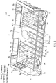
FIG. 2 is a perspective view of the battery tray; -
FIG. 3 is a plan view of the battery tray; -
FIG. 4 is a bottom view of the battery tray; -
FIG. 5 is an enlarged view of a boxed portion V inFIG. 3 ; -
FIG. 6 is a cross-sectional view taken along line VI-VI ofFIG. 3 ; -
FIG. 7 is a cross-sectional view taken along line VII-VII ofFIG. 3 ; -
FIG. 8 is a partially cross-sectional view of a molding machine, which view shows a condition in which a wood member is temporarily secured to an upper die of a molding die unit of the molding machine; -
FIG. 9 is a partially cross-sectional view of the molding machine, which view shows a condition in which the molding die unit is closed; -
FIG. 10 is a partially plan view of a battery tray according to a first modified form, in which a wood insert has anchor devices; -
FIG. 11 is a partially cross-sectional view of a battery tray according to a second modified form, in which a wood insert has anchor devices; -
FIG. 12 is a partially cross-sectional view of a battery tray according to a third modified form, in which a wood insert has anchor devices; -
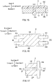
FIG. 13 is a partially cross-sectional view of a battery tray according to a fourth modified form, in which a wood insert has anchor devices; -
FIG. 14 is a partially cross-sectional view of a battery tray according to a fifth modified form, in which a resin substrate has anchor portions that are different from the anchor portions formed in the resin substrate in the embodiment; -
FIG. 15 is a partially cross-sectional view of a battery tray according to a sixth modified form, in which a resin substrate has anchor portions that are different from the anchor portions formed in the resin substrate of the embodiment; -
FIG. 16 is a partially plan view of a battery tray according to a seventh modified form, in which a resin substrate has ribs that are different from the ribs formed in the resin substrate of the embodiment; and -
FIG. 17 is a partially plan view of a battery tray according to a eighth modified form, in which a resin substrate has ribs that are different from the ribs formed in the resin substrate of the embodiment. - In the following, a molded article according to a representative embodiment of the present disclosure and a manufacturing method thereof will be described with reference to
FIGS. 1 to 9 . - In this embodiment, a battery tray 2 (
FIGS. 1 to 4 ) on which a battery VT is positioned is exemplified as the molded article. Further, forward and backward, rightward and leftward, and upward and downward in the drawings may respectively correspond to forward and backward, rightward and leftward, and upward and downward of a vehicle to which thebattery tray 2 is attached. Further, a longitudinal (front-back) direction, a vertical direction and a lateral direction in the description may respectively referred to as a longitudinal (front-back) direction, a vertical direction and a lateral direction of the vehicle or thebattery tray 2. - Generally, the
battery tray 2 may be positioned in an engine compartment, a space under a seat, a luggage storage area, a space under a front side step or other such spaces. Further, as shown inFIG. 1 , the battery VT to be positioned on thebattery tray 2 may be a rectangular parallelepiped heavy device having four (right and left, front and rear) elongated flanged portions formed in four lower peripheries (only the left flangedportion 2v is shown for simplification). The battery VT positioned on thebattery tray 2 may be secured to thebattery tray 2 via afixture mechanism 5, so as to be integrated with thebattery tray 2. - As shown in
FIG. 2 , thebattery tray 2 may have a rectangular open-sided traymain body 4. The traymain body 4 may be composed of a resin substrate and a wood insert embedded in the resin substrate in order to reduce in weight and to increase in strength and rigidity. That is, the traymain body 4 may be composed of the resin substrate of which a portion is replaced with the wood insert. The resin substrate may includehorizontal substrate portions vertical substrate portion 8. Conversely, the wood insert may includewood members horizontal substrate portions 21 and 22 (the resin substrate) and the embeddedwood members tray bottom portion 6. Thetray bottom portion 6 may be referred to as a (resin-wood) composite wall portion. Further, as shown inFIGS. 3 and4 , thewood members horizontal substrate portions inner surface 6U and a lower orouter surface 6D) of thetray bottom portion 6. Conversely, the vertical substrate portion 8 (the resin substrate) may extend along a front and back sides and a right side of thetray bottom portion 6, so as to form a tray wall portion. Therefore, thevertical substrate portion 8 may be herein after referred to as thetray wall portion 8. Further, thetray wall portion 8 may be referred to as a (resin) solid wall portion. - The tray
main body 4 may be formed by insert molding (injection molding) using various resins. Examples of the resins are a polypropylene resin, a polyethylene resin, ABS resin, a polycarbonate resin, a polyester resin, a polyamide resin, a polyacetal resin, an acrylic resin, a styrene resin and a polyvinyl chloride resin. Further, the resins may respectively be used independently or in combination. Further, the resins may contain reinforcing materials (filler), e.g., wood powder, metallic powder (particulate or fiber), talc, carbon fiber and glass fiber. The reinforcing materials having 2 mm or less (more preferably 150 micrometer or less) in size may preferably be used. Further, a mixing ratio of the resins and the reinforcing materials may preferably be 80:20 to 60:40. Generally, the resins containing the reinforcing materials may increase the molded resin substrate in specific gravity. For example, the polypropylene resin (specific gravity of 0.9) containing an appropriate amount of wood powder may substantially be increased from 0.9 to about 1.0 in specific gravity. Similarly, the polypropylene resin containing an appropriate amount of metallic powder may substantially be increased from 0.9 to about 1.2 in specific gravity. - As shown in
FIG. 2 , the tray wall portion 8 (the solid wall portion) may extend along a periphery (the front and back sides and the right side) of thetray bottom portion 6, so as to surround the battery VT positioned on the battery tray 2 (the tray bottom portion 6) on three sides. Thetray wall portion 8 may be composed of a fronttray wall portion 8a, a reartray wall portion 8b and a righttray wall portion 8c, so as to have a U-shape as viewed from above. Therefore, the battery VT may be introduced into thebattery tray 2 at a left side (i.e., an open side). - Further, the tray wall portion 8 (the front
tray wall portion 8a, the reartray wall portion 8b and the righttray wall portion 8c) may have a plurality of horizontalelongated protrusions 8d and a plurality ofvertical reinforcement ribs 8e that are respectively formed in an inner surface thereof. Theelongated protrusions 8d may horizontally extend along thetray wall portion 8, so as to be positioned substantially parallel to thebottom portion 6 at the same height as each other. Further, theelongated protrusions 8d may be configured such that the flanged portions (except for the leftflanged portion 2v) formed in the battery VT can fit in a space formed between theelongated protrusions 8d and thetray bottom portion 6 when the battery VT is positioned on thebattery tray 2. Thereinforcement ribs 8e may be positioned on theelongated protrusions 8d, so as to be laterally juxtaposed to each other at certain intervals. - The tray bottom portion 6 (the composite wall portion) may be composed of the
horizontal substrate portions 21 and 22 (which may respectively be referred to as a firsthorizontal substrate portion 21 and a second horizontal substrate portion 22) and thewood members wood member 10, a second (back)wood member 11 and a third (left) wood member 12). The first tothird wood members horizontal substrate portions tray wall portion 8 in boundary portions or connectingportions FIG. 3 , thetray bottom portion 6 may be divided to a right (first) orbattery holding portion 6a and a left (second) orbattery guiding portion 6b between which a boundary line is formed. Thebattery holding portion 6a may include the firsthorizontal substrate portion 21 and the first andsecond wood members battery guiding portion 6b may include the secondhorizontal substrate portion 22 and thethird wood member 12. Further, the secondhorizontal substrate portion 22 may substantially be divided into three portions, i.e., a front secondhorizontal substrate portion 22a, a back secondhorizontal substrate portion 22b and a left secondhorizontal substrate portion 22c via thethird wood member 12. - The resin substrate (the
horizontal substrate portions retainer ribs third retainer ribs FIG. 3 , the first andsecond retainer ribs wood members portions upper surface 6U of thetray bottom portion 6. The first andsecond retainer ribs anchor portions wood members FIGS. 5 to 7 ), so as to be securely connected to thewood members FIG. 4 , thethird retainer ribs 42 may be configured to extend along thewood members lower surface 6D of thetray bottom portion 6. - As shown in
FIGS. 2 to 4 , thehorizontal substrate portions attachment bases horizontal substrate portion 21, the front secondhorizontal substrate portion 22a and the back secondhorizontal substrate portion 22b. The seating bases 7a, 7b and 7c are vertically projected at thelower surface 6D of the tray bottom portion 6 (FIG. 2 ). The attachment bases 7a, 7b and 7c may function as attachment portions to secure thebattery tray 2 to a vehicle body (not shown) by bolting. Further, thehorizontal substrate portions holes 5H for thefixture mechanism 5. In particular, the connectingholes 5H may respectively formed in the front secondhorizontal substrate portion 22a and the back secondhorizontal substrate portion 22b (i.e., thebattery guiding portion 6b of the tray bottom portion 6). - As previously described, the
wood members tray bottom portion 6 may respectively be referred to as the first (front), second (back) and third (left)wood members FIGS. 3 and4 , each of the first andsecond wood members third wood member 12 may be formed as a longitudinally elongated slim rectangular plate-shaped member having a substantially uniform thickness. Further, as shown inFIGS. 6 and 7 , thewood members anchor portions main body 4. - The type of the
wood members wood members wood members wood members substrate portions 21 and 22). For example, thewood members - As previously described, the
tray bottom portion 6 may include thehorizontal substrate portions third wood members FIGS. 3 and4 , the first tothird wood members horizontal substrate portions inner surface 6U and theouter surface 6D of thetray bottom portion 6. Further, in thebattery holding portion 6a of thetray bottom portion 6, the first andsecond wood members horizontal substrate portion 21. Conversely, in thebattery guiding portion 6b of thetray bottom portion 6, thethird wood member 12 may be positioned in a longitudinally central portion of the secondhorizontal substrate portion 22, i.e., positioned between the front secondhorizontal substrate portion 22a and the back secondhorizontal substrate portion 22b. - As previously described, the first to
third wood members horizontal substrate portions tray wall portion 8 in the boundary portions or connectingportions portion 31, a second (back) connectingportion 32 and a third (left) connecting portion 33). That is, thetray bottom portion 6 may have the first to third connectingportions third wood members horizontal substrate portions tray wall portion 8. In particular, the first connectingportion 31 may be positioned around thefirst wood member 10, so as to connect thefirst wood member 10 to the firsthorizontal substrate portion 21, the second horizontal substrate portion 22 (the front secondhorizontal substrate portion 22a) and thetray wall portion 8. The second connectingportion 32 may be positioned around thesecond wood member 11, so as to connect thesecond wood member 11 to the firsthorizontal substrate portion 21, the second horizontal substrate portion 22 (the back secondhorizontal substrate portion 22b) and thetray wall portion 8. Further, the third connectingportion 33 may be positioned around thethird wood member 12, so as to connect thethird wood member 12 to the firsthorizontal substrate portion 21 and the second horizontal substrate portion 22 (the front secondhorizontal substrate portion 22a, the back secondhorizontal substrate portion 22b and the left secondhorizontal substrate portion 22c). - The first to
third wood members portions horizontal substrate portions portions first wood member 10 and the firsthorizontal substrate portion 21 may be described as a representative of the first tothird wood members horizontal substrate portions FIG. 6 , the first connectingportion 31 may be defined as a joining portion of anend surface 10E of thefirst wood member 10 and anend surface 21E of the firsthorizontal substrate portion 21. Theend surface 10E of thefirst wood member 10 may be formed as a vertical surface substantially perpendicular to upper and lower surfaces of the first wood member 10 (i.e., perpendicular to the both surfaces of the tray bottom portion 6). Similarly, theend surface 21E of the firsthorizontal substrate portion 21 may be defined as a vertical surface substantially perpendicular to upper and lower surfaces of the first horizontal substrate portion 21 (i.e., perpendicular to the both surfaces of the tray bottom portion 6) and corresponding to theend surface 10E of thefirst wood member 10. - As shown in
FIG. 6 , thefirst wood member 10 may have a thickness T1 in the peripheral portion adjacent to the first connectingportion 31. Conversely, the firsthorizontal substrate portion 21 may have a thickness T2 (a predetermined thickness) in the peripheral portion adjacent to the first connectingportion 31. The thickness T1 may be determined to be substantially equal to the thickness T2. That is, a ratio of the thickness T1 to the thickness T2 may be determined to approximately 1.0 with an allowable margin of error of plus or minus 5%. Further, in this embodiment, thefirst wood member 10 may have a substantially uniform thickness over the entire area thereof. That is, thefirst wood member 10 may have a thickness equal to the thickness T1 over the entire area thereof (except for the through holes H). Further, the ratio of the thickness T1 to the thickness T2 may be determined to a range of not less than 0.7 and not greater than 1.0, preferably not less than 0.8 and not greater than 1.0. - As previously described, the resin substrate (the first and second
horizontal substrate portions first retainer ribs 40, thesecond retainer ribs 41 and thethird retainer ribs 42 that are integrally formed therein in order to reinforce thetray bottom portion 6. As shown inFIG. 3 , the first andsecond retainer ribs third wood members upper surface 6U of thetray bottom portion 6. Further, the first andsecond retainer ribs battery holding portion 6a and thebattery guiding portion 6b) in a symmetrical fashion about a lateral axis. - The
first retainer ribs 40 may respectively be formed in the fronttray wall portion 8a and the reartray wall portion 8b so as to longitudinally extend along the first andsecond wood members portions first retainer ribs 40 formed in the fronttray wall portion 8a and thefirst retainer ribs 40 formed in the reartray wall portion 8b may respectively be referred to as the frontfirst retainer ribs 40 and the rearfirst retainer ribs 40. The frontfirst retainer ribs 40 may be laterally aligned at certain intervals. Similarly, the rearfirst retainer ribs 40 may be laterally aligned at certain intervals. Further, each of the front and rearfirst retainer ribs 40 may preferably have a triangular shape as viewed from above. - Conversely, the
second retainer ribs 41 may respectively be formed in the righttray wall portion 8c so as to laterally extend along the first andsecond wood members portions second retainer ribs 41 formed in the righttray wall portion 8c and extending over thefirst wood member 10 may be referred to as the right-frontsecond retainer ribs 41. Conversely, thesecond retainer ribs 41 formed in the righttray wall portion 8c and extending over thesecond wood member 11 may be referred to as the right-rearsecond retainer ribs 41. The (right-front and right-rear)second retainer ribs 41 may be positioned longitudinally adjacent to each other at certain intervals. Further, each of thesecond retainer ribs 41 may have a triangular shape as viewed from above. - Further, as shown in
FIGS. 2 and3 , the resin substrate (the first and secondhorizontal substrate portions tray wall portion 8a and the reartray wall portion 8b at theupper surface 6U of thetray bottom portion 6 along the boundary line formed between thebattery holding portion 6a and thebattery guiding portion 6b of thetray bottom portion 6. Some of thesecond retainer ribs 41 may be formed in the longitudinal bridging rib so as to extend along the first tothird wood members second retainer ribs 41 extending over thethird wood member 12 may be referred to as the left-centralsecond retainer ribs 41. Conversely, thesecond retainer ribs 41 extending over the first andsecond wood members second retainer ribs 41 and the left-rearsecond retainer ribs 41. The left-centralsecond retainer ribs 41, the left-frontsecond retainer ribs 41 and the left-rearsecond retainer ribs 41 may respectively be positioned longitudinally adjacent to each other at certain intervals. Further, the left-frontsecond retainer ribs 41 and the left-rearsecond retainer ribs 41 may respectively include specialsecond retainer ribs battery holding portion 6a of thetray bottom portion 6. - As shown in
FIG. 4 , thethird retainer ribs 42 may be formed in the firsthorizontal substrate portion 21 and the vertical substrate portion 8 (the front, rear and righttray wall portions second wood members inner surface 6D of thetray bottom portion 6. Further, unlike the first andsecond retainer ribs third retainer ribs 42 may be formed as specially arranged continuous ribs that are positioned on the tray bottom portion 6 (thebattery holding portion 6a) in a symmetrical fashion about the lateral axis. Thethird retainer ribs 42 may be configured to partially overlap thefirst retainer ribs 40 and thesecond retainer ribs 41 with the first andsecond wood members third retainer ribs 42 may include six diagonalfirst rib sections 42a, four diagonalsecond rib sections 42b, two transversethird rib sections 42c and three longitudinalfourth rib sections 42d that intersect with each other. Thethird rib sections 42c may be configured to be vertically aligned with the specialsecond retainer ribs second retainer ribs 41 with the first andsecond wood members fourth rib sections 42d may be configured to be vertically aligned with the bridging rib formed in the resin substrate at theupper surface 6U of thetray bottom portion 6 with the first, second andthird wood members third retainer ribs 42 may preferably be formed so as to be continuous with theattachment bases - As previously described, the first and
second retainer ribs anchor portions third wood members FIGS. 5 to 7 ). As shown inFIG. 6 , theanchor portions 50 formed in thefirst retainer ribs 40 may be configured to penetrate the first wood member 10 (the second wood member 11) and to be integrated with thethird retainer ribs 42 in thelower surface 6D of thetray bottom portion 6. Conversely, as shown inFIG. 7 , theanchor portions 51 formed in thesecond retainer ribs 41 may be configured to penetrate thethird wood member 12 and to reach thelower surface 6D of thetray bottom portion 6. - A molding machine (an injection molding machine) MM may be used in order to manufacture the battery tray 2 (the tray main body 4). As shown in
FIGS. 8 and 9 , the molding machine MM may include a molding die unit having an upper orfirst die 11m and a lower orsecond die 12m. As shown inFIG. 9 , thefirst die 11m and thesecond die 12m may be configured to define amolding cavity 14m between aninner surface 11s of thefirst die 11m and aninner surface 12s of thesecond die 12m when the molding die unit is closed. Themolding cavity 14m may have a profile or shape corresponding to the tray main body 4 (thetray bottom portion 6 and the tray wall portion 8). Further, themolding cavity 14m may be composed of afirst cavity portion 114m in which the resin substrate (thehorizontal substrate portions second cavity portion 214m in which the first tothird wood members first wood member 10 is shown) are previously positioned. - As shown in
FIG. 9 , themolding cavity 14m (thefirst cavity portion 114m) may have a height equal to the thickness T2 of the first horizontal substrate portion 21 (FIG. 6 ). Further, thefirst die 11m may have a plurality of temporarily holdingdevices 16m formed in theinner surface 11s thereof and configured to temporarily hold the first tothird wood members first die 11m until the molding die unit is closed. Further, various types of pins may preferably be used as the temporarily holdingdevices 16m. The first tothird wood members first wood member 10 is shown) to be positioned in themolding cavity 14m (thesecond cavity portion 214m) may be temporarily held on theinner surface 11s with the pins stuck therein. - In order to mold the battery tray 2 (the tray main body 4) that is composed of the resin substrate and the wood insert embedded in the resin substrate, in a first molding step, the first to
third wood members first die 11m using the temporarily holdingdevices 16m in a condition in which the molding die unit is opened (FIG. 8 ). Thereafter, the molding die unit is closed in order to form themolding cavity 14m, i.e., thefirst cavity portion 114m and thesecond cavity portion 214m in which the first tothird wood members FIG. 9 ). Further, as shown inFIG. 9 , in themolding cavity 14m thus formed, thefirst cavity portion 114m may be separated from thesecond cavity portion 214m by cavity boundaries B corresponding to theend surface 10E of thefirst wood member 10. - Next, in a second molding step, a molding material (resin) M may be injected into the
molding cavity 14m (thefirst cavity portion 114m), so as to mold the resin substrate, i.e., thehorizontal substrate portions vertical substrate portion 8. As a result, the molded resin substrate may be combined with the wood insert in the cavity boundaries B, so that the traymain body 4 may be formed as a unit. In the traymain body 4 thus formed, the resin substrate (thehorizontal substrate portions third wood members third retainer ribs anchor portions - As shown in
FIG. 8 , before molding, thefirst wood member 10 may have a thickness T3 in the peripheral portion (theend surface 10E) thereof. In this embodiment, a ratio of the thickness T3 to a predetermined height of themolding cavity 14m (which correspond to the thickness T2 of the first horizontal substrate portion 21) may be determined to approximately 1.0 with an allowable margin of error of plus or minus 5%. Therefore, the molding material M may be prevented from entering thesecond cavity portion 214m, i.e., prevented from wrapping around thefirst wood member 10 positioned in thesecond cavity portion 214m, during molding, so that thefirst wood member 10 may be prevented from being compressed in the thickness direction by the molding material M. As a result, the moldedbattery tray 2 in which the ratio of the thickness T1 to the thickness T2 is equal to 1.0 may be produced (FIG. 6 ). Therefore, the wood insert (the first tothird wood members horizontal substrate portions inner surface 6U and theouter surface 6D of thetray bottom portion 6. Further, in the moldedbattery tray 2 thus produced, the first tothird wood members horizontal substrate portions vertical substrate portion 8 in the connectingportions third wood members end surface 10E of the first wood member 10) and end surfaces of thehorizontal substrate portions 21 and 22 (e.g., theend surface 21E of the first horizontal substrate portion 21). - Further, the ratio of the thickness T3 to the thickness T2 may be determined to a range of not less than 0.8 and less than 1.0, preferably not less than 0.85 and less than 1.0. When the ratio of the thickness T3 to the thickness T2 falls within such a range, after molding, the ratio of the thickness T1 (
FIG. 6 ) of thefirst wood member 10 to the thickness T2 may be held in a range of not less than 0.7 to less than 1.0 even if thefirst wood member 10 is compressed or thinned due to an injection pressure of the molding material M penetrating into thesecond cavity portion 214m, i.e., protruding onto or wrapping around thefirst wood member 10 positioned in thesecond cavity portion 214m, during molding. That is, the molding material M may be prevented from being excessively entering thesecond cavity portion 214m, so that the moldedbattery tray 2 may be prevented from being excessively increased in weight. Further, thefirst wood member 10 may be prevented from being excessively compressed by the molding material M penetrating into thesecond cavity portion 214m. As a result, thefirst wood member 10 may be prevented from being warped. - Further, the ratio of the thickness T3 to the thickness T2 may be determined to a range of not less than 1.0 and less than 1.6, preferably not less than 1.0 and less than 1.25, as necessary. When the ratio of the peripheral thickness T3 to the peripheral thickness T2 falls within such a range, the
first wood member 10 may be compressed to be reduced in thickness such that the ratio of the peripheral thickness T3 to the peripheral thickness T2 may be reduced to approximately 1.0 when the molding die unit is closed. Therefore, the molding material M may be prevented from entering thesecond cavity portion 214m during molding. As a result, the moldedbattery tray 2 in which the ratio of the thickness T1 to the thickness T2 is equal to 1.0 may be produced (FIG. 6 ). Further, in the moldedbattery tray 2, the wood insert (the first tothird wood members horizontal substrate portions inner surface 6U and theouter surface 6D of thetray bottom portion 6. - In order to secure the battery VT to the
battery tray 2, the battery VT may be laterally slid or moved along thebattery guiding portion 6b of thetray bottom portion 6 from left so as to be positioned on thebattery holding portion 6a of thetray bottom portion 6. Thereafter, the battery VT may be connected to thebattery tray 2 by thefixture mechanism 5. - In particular, as shown in
FIG. 1 , thefixture mechanism 5 may have an upper orfirst fixture plate 5a, a lower orsecond fixture plate 5b and bolts BT and screws. In order to secure the battery VT to thebattery tray 2, thefirst fixture plate 5a and thesecond fixture plate 5b may be applied to thebattery tray 2 with the leftflanged portion 2v and thebattery guiding portion 6b interleaved therebetween. Thefirst fixture plate 5a and thesecond fixture plate 5b thus positioned may be connected to each other by the bolts BT passed through the connectingholes 5H formed in thebattery guiding portion 6b and the screws, so that the battery VT is secured to thebattery tray 2. Thus, the battery VT is integrated with thebattery tray 2 while it is positioned on thetray bottom portion 6. Thebattery tray 2 to which the battery VT is secured may then be attached to the vehicle body by bolting using theattachment bases tray bottom portion 6. - According to the embodiment, the molded
battery tray 2 may be configured such that the first tothird wood members horizontal substrate portions 21 and 22 (the resin substrate) with their upper and lower (inner and outer) surfaces substantially completely exposed on theinner surface 6U and theouter surface 6D of thetray bottom portion 6. Therefore, thebattery tray 2 may have a good appearance. Further, thebattery tray 2 may be reduced in weight due to the embedded first tothird wood members battery tray 2 thus produced, the first tothird wood members horizontal substrate portions vertical substrate portion 8 in the connectingportions third wood members end surface 10E of the first wood member 10) and the end surfaces of thehorizontal substrate portions 21 and 22 (e.g., theend surface 21E of the first horizontal substrate portion 21). Therefore, the first tothird wood members horizontal substrate portions vertical substrate portion 8 with a substantial connecting strength. - Further, the molded
battery tray 2 may have the first tothird retainer ribs second retainer ribs wood members upper surface 6U of thetray bottom portion 6. Conversely, thethird retainer ribs 42 may extend along thewood members lower surface 6D of thetray bottom portion 6. Thus, thetray bottom portion 6 may be effectively reinforced by the first tothird retainer ribs - Further, the first and
second retainer ribs anchor portions anchor portions 50 formed in thefirst retainer ribs 40 may penetrate the first wood member 10 (the second wood member 11), so as to be integrated with thethird retainer ribs 42 in thelower surface 6D of the tray bottom portion. Conversely, theanchor portions 51 formed in thesecond retainer ribs 41 may penetrate thethird wood member 12, so as to terminate in thelower surface 6D of thetray bottom portion 6. Theanchor portions horizontal substrate portions third wood members second retainer ribs second retainer ribs tray bottom portion 6 due to theanchor portions - According to the manufacturing method of the
battery tray 2, the molding material M may be prevented from entering thesecond cavity portion 214m, i.e., prevented from wrapping around thefirst wood member 10 positioned in thesecond cavity portion 214m, during molding. Therefore, in the moldedbattery tray 2 manufactured by the method, the first tothird wood members horizontal substrate portions inner surface 6U and theouter surface 6D of thetray bottom portion 6. Further, thefirst wood member 10 may be prevented from being compressed by the molding material M. In addition, the first tothird wood members inner surface 11s of thefirst die 11m using the temporarily holdingdevice 16m. Therefore, the first tothird wood members - Examples of the molded article will now be described. Further, the following examples are illustrative and should not be construed as limitations of the disclosure.
- Tests were performed using example molded articles (Examples 1-4) and control molded articles (Control 1-4) in order to evaluate a lightening effect of wood members (wood insert) on the example molded articles and an amount of molding material wrapping around the wood members during molding. Results are shown in Table 1 and Table 2.
- Further, a test piece (example molded article) of Example 1 was formed by injection molding (insert molding) using a plywood board (thickness of 2.0 mm; specific gravity of 0.4 to 0.7) as the wood member and a polypropylene resin containing wood powder (specific gravity of 1.02). Further, a molding machine was configured such that a height of a molding cavity may be equal to a thickness (e.g., 2.5 mm) of a substrate portion (resin substrate). Further, an injection pressure of the molding material was set to 40 Mpa (408 kg/cm2). Each of test pieces (example molded articles) of Example 2 to 4 and test pieces (control molded articles) of
Control 1 to 4 was formed in the same manner as Example 1 except that the thickness of the plywood board and the thickness of the substrate portion. Further, a molded article for comparison was formed in the same manner as Example 1 except that the plywood board was omitted.Table 1 Thickness of Substrate Portion (mm) Thickness of Wood Member (mm) Compression Rate (%) Lightening Effect Before Molding After Molding Example 1 2.5 2.0 1.8 10 Yes Example 2 2.3 2.0 1.9 5 Yes Example 3 2.0 2.0 2.0 0 Yes Example 4 2.0 2.5 2.3 8 Yes Control 1 4.0 2.0 1.0 50 No Control 23.5 2.0 1.0 50 No Control 3 3.0 2.0 1.5 25 Yes Control 4 1.5 2.5 - - - Table 2 Ratio of Thickness of Wood Member to Thickness of Substrate Portion (%) Amount of Molding Material Wrapping Around Wood Member Before Molding After Molding Example 1 80 72 Small Example 2 87 83 Small Example 3 100 100 Nothing Example 4 125 115 Nothing Control 1 50 25 Large Control 2 57 29 Large Control 3 67 50 Large Control 4 167 - - - The results shown in Tables 1 and 2 demonstrate that each of the example molded articles of Examples 1 to 4 has a lightning effect. This means that when a ratio of a thickness of a wood member (before molding) to a thickness of a substrate portion falls within a range of 0.8 to 1.25 (80% to 125%), a molded article formed using such a wood member may have a lightening effect. In particular, the example molded article of Example 3 has a weight of 620 grams whereas the molded article for comparison has a weight of 658 grams. Thus, the example molded article of Example 3 is determined to have a lightening effect. Each of the example molded articles of Examples 1, 2 and 4 and the control molded articles of
Controls 1 to 3 is determined in the same manner as the example molded article of Example 1. - Further, the results shown in Tables 1 and 2 demonstrate that each of the control molded articles of
Controls 1 to 3 has no lightning effect except for the control molded article of Control 3. This means that when the ratio of the thickness of the wood member (before molding) to the thickness of the substrate portion is less than about 0.6 (i.e., 60%), a molded article formed using such a wood member has no lightening effect. Further, when the ratio of the thickness of the wood member (before molding) to the thickness of the substrate portion is greater than 1.25 (125%), in particular 1.67 (167%), a molding die unit of the molding machine cannot be closed (Control 4). - Conversely, the results shown in Table 2 demonstrate that in each of the example molded articles of Examples 1 to 4, the molding material may substantially be prevented from wrapping around the wood member during molding whereas in each of the control molded articles of
Controls 1 to 4, the molding material may considerably wrap around the wood member during molding. This means that only when the ratio of the thickness of the wood member to the thickness of the substrate portion is 0.8 (i.e., 80%) or more before molding, the molding material can be effectively prevented from wrapping around the wood member during molding, so that the ratio of the thickness of the wood member to the thickness of the substrate portion can be kept to 0.7 (i.e., 70%) or more after molding. Further, in each of the example molded articles of Examples 1 to 4, upper and lower (inner and outer) surfaces of the wood member are substantially completely exposed. Thus, each of the example molded articles of Examples 1 to 4 has a good appearance in addition to a lightening effect. - Further, in the example molded article of Examples 3 in which the ratio of the thickness of the wood member to the thickness of the substrate portion is 1.0 (i.e., 100%) before molding, the molding material can be completely prevented from wrapping around the wood member during molding, so that the ratio of the thickness of the wood member to the thickness of the substrate portion can be kept to 1.00 (i.e., 100%) even after molding. Thus, the example molded article of Example 3 has an excellent appearance in addition to a lightening effect.
- Naturally, various changes and modifications may be made to the present disclosure without departing from the scope of the disclosure.
- As shown in
FIG. 10 , in a first modified form, thefirst wood member 10 and the firsthorizontal substrate portion 21 may respectively be replaced with a modifiedfirst wood member 10A and a modified firsthorizontal substrate portion 21A. The modifiedfirst wood member 10A and the modified firsthorizontal substrate portion 21A may be integrated with each other via a modified first connectingportion 31A. Further, the modifiedfirst wood member 10A may have a plurality ofanchor devices 52 formed in an end surface thereof. Each of theanchor devices 52 may be formed as a projection having a T-shape in transverse cross section. Further, each of theanchor devices 52 may be configured to engage each of recesses formed in an end surface of the modified firsthorizontal substrate portion 21A. According to the first modified form, the modifiedfirst wood member 10A may be securely integrated with the modified firsthorizontal substrate portion 21A in the modified first connectingportion 31A due to engagement of theanchor devices 52 formed in the modifiedfirst wood member 10A and the recesses formed in the modified firsthorizontal substrate portion 21A. - As shown in
FIG. 11 , in a second modified form, thefirst wood member 10 and the firsthorizontal substrate portion 21 may respectively be replaced with a modifiedfirst wood member 10B and a modified firsthorizontal substrate portion 21B. The modifiedfirst wood member 10B and the modified firsthorizontal substrate portion 21B may be integrated with each other via a modified first connectingportion 31B. Further, the modifiedfirst wood member 10B may have ananchor device 53 formed in and along an end surface thereof. Theanchor device 53 may be formed as a wedge-shaped engagement projection. Further, theanchor device 53 may be configured to fit in arecess 21H formed in an end surface of the modified firsthorizontal substrate portion 21B and having a V-shape in vertical cross section. According to the second modified form, the modifiedfirst wood member 10B may be securely integrated with the modified firsthorizontal substrate portion 21B in the modified first connectingportion 31B due to engagement of theanchor device 53 formed in the modifiedfirst wood member 10B and therecess 21H formed in the modified firsthorizontal substrate portion 21B. - As shown in
FIG. 12 , in a third modified form, thefirst wood member 10 and the firsthorizontal substrate portion 21 may respectively be replaced with a modified first wood member 10C and a modified firsthorizontal substrate portion 21C. The modified first wood member 10C and the modified firsthorizontal substrate portion 21C may be integrated with each other via a modified first connectingportion 31C. Further, the modified first wood member 10C may have ananchor device 10H formed in and along an end surface thereof. Theanchor device 10H may be formed as a recess formed in an end surface of the modified first wood member 10C and having a V-shape in vertical cross section. Further, theanchor device 10H may be configured to engage a wedge-shapedengagement projection 54 formed in an end surface of the modified firsthorizontal substrate portion 21C. According to the third modified form, the modified first wood member 10C may be securely integrated with the modified firsthorizontal substrate portion 21C in the modified first connectingportion 31C due to engagement of theanchor device 10H formed in the modified first wood member 10C and theengagement projection 54 formed in the modified firsthorizontal substrate portion 21C. - As shown in
FIG. 13 , in a fourth modified form, thefirst wood member 10 and the firsthorizontal substrate portion 21 may respectively be replaced with a modifiedfirst wood member 10D and a modified firsthorizontal substrate portion 21D. The modifiedfirst wood member 10D and the modified firsthorizontal substrate portion 21D may be integrated with each other via a modified first connectingportion 31D. Further, the modifiedfirst wood member 10D may have ananchor device 55 formed in and along an end surface thereof. Theanchor device 55 may be formed as an oblique surface. Further, theanchor device 55 may be configured to engage anoblique surface 56 formed in an end surface of the modified firsthorizontal substrate portion 21D. According to the fourth modified form, the modifiedfirst wood member 10D may be securely integrated with the modified firsthorizontal substrate portion 21D in the modified first connectingportion 31D due to engagement of the anchor device 55 (oblique surface) formed in the modifiedfirst wood member 10D and theoblique surface 56 formed in the modified firsthorizontal substrate portion 21D. - As shown in
FIG. 14 , in a fifth modified form, theanchor portions 51 formed in thesecond retainer ribs 41 may be replaced with modified anchor portions 51A. Similar to theanchor portion 51, the modified anchor portions 51A may be configured to penetrate thethird wood member 12 and to reach thelower surface 6D of thetray bottom portion 6. However, the modified anchor portions 51A may have countersunkhead portions 51a that are embedded in thethird wood member 12. The countersunkhead portions 51a of the modified anchor portions 51A may function as retainers or stoppers. Therefore, the modified anchor portions 51A thus constructed may function to more surely or reliably combine the firsthorizontal substrate portion 21 to thethird wood member 12 via thesecond retainer ribs 41. - As shown in
FIG. 15 , in a sixth modified form, theanchor portions 51 formed in thesecond retainer ribs 41 may be replaced with modifiedanchor portions 51B. Similar to theanchor portion 51, the modifiedanchor portions 51B may be configured to penetrate thethird wood member 12 and to reach thelower surface 6D of thetray bottom portion 6. However, the modifiedanchor portions 51B may havehead portions 51b projected on thelower surface 6D of thetray bottom portion 6 and having a substantially semicircular shape in cross section. Thehead portions 51a of the modifiedanchor portions 51B may function as retainers or stoppers. Therefore, the modifiedanchor portions 51B thus constructed may function to more surely or reliably combine the firsthorizontal substrate portion 21 to thethird wood member 12 via thesecond retainer ribs 41. Further, thehead portions 51 may have various shapes, e.g., a square shape, a trapezoidal shape and a triangular shape in cross section. - As shown in
FIG. 16 , in a seventh modified form, thefirst wood member 10, the firsthorizontal substrate portion 21 and thetray wall portion 8 may respectively be replaced with a modifiedfirst wood member 10E, a modified firsthorizontal substrate portion 21E and a modifiedtray wall portion 8E. The modifiedfirst wood member 10E, the modified firsthorizontal substrate portion 21E and the modifiedtray wall portion 8E may be integrated with each other via a modified first connectingportion 31E. Further, the modifiedtray wall portion 8E and the modified firsthorizontal substrate portion 21E may respectively have a pair of (front)retainer ribs retainer ribs second retainer ribs retainer ribs retainer ribs first wood member 10E. Theretainer ribs horizontal substrate portion 21E and the modifiedtray wall portion 8E with the modifiedfirst wood member 10E, so as to reinforce thetray bottom portion 6. - As shown in
FIG. 17 , in an eighth modified form, thefirst wood member 10, the firsthorizontal substrate portion 21, the secondhorizontal substrate portion 22 and thetray wall portion 8 may respectively be replaced with a modifiedfirst wood member 10F, a modified firsthorizontal substrate portion 21F, a modified secondhorizontal substrate portion 22F and a modifiedtray wall portion 8F. The modifiedfirst wood member 10F, the modified firsthorizontal substrate portion 21F, the modified secondhorizontal substrate portion 22F and the modifiedtray wall portion 8F may be integrated with each other via a modified first connectingportion 31F. Further, the modified firsthorizontal substrate portion 21F, the modified secondhorizontal substrate portion 22F and the modifiedtray wall portion 8F may have a pair ofretainer ribs second retainer ribs retainer ribs first wood member 10F. In particular, the pair ofretainer ribs first wood member 10F. Theretainer ribs horizontal substrate portion 21F, the modified secondhorizontal substrate portion 22F and the modifiedtray wall portion 8F with the modifiedfirst wood member 10F, so as to reinforce thetray bottom portion 6. Further, the pair ofretainer ribs anchor portion 50F as necessary. Theanchor portion 50F may preferably be positioned in an intersection point of the pair ofretainer ribs anchor portion 50F may preferably penetrate the first modifiedwood member 10 in its thickness direction. - Further, in the
tray bottom portion 6 of the embodiment, thehorizontal substrate portions 21 and 22 (the resin substrate) and the first tothird wood members horizontal substrate portions third wood members third wood members battery holding portion 6a. However, the first tothird wood members battery holding portion 6a and thebattery guiding portion 6b. Further, in the embodiment, each of the first tothird wood members third wood members - Further, in the embodiment, the
tray wall portion 8 is formed as a portion of the resin substrate. That is, thetray wall portion 8 is formed as the solid wall portion that does not include the wood insert (wood members). However, thetray wall portion 8 may include the wood insert embedded therein. That is, thetray wall portion 8 may be formed as the composite wall portion. - Further, the
anchor portions second retainer ribs anchor portions wood members anchor portions wood members anchor portions anchor portions anchor portions 51A and 51B. Naturally, theanchor portions - Further, the first to
third retainer ribs third retainer ribs retainer ribs retainer ribs third retainer ribs - Further, in the embodiment, the
battery tray 2 is exemplified as the molded article. However, an instrument panel, a pillar garnish, a console and a door trim may be exemplified as the molded article other than thebattery tray 2. - Further, in the manufacturing method of the
battery tray 2, the pins are used as the temporarily holdingdevices 16m, However, various types of wires and hooks and suction devices may be used as the temporarily holdingdevices 16m. Further, in the manufacturing method, the temporarily holdingdevices 16m are formed in theinner surface 11s of thefirst die 11m. However, the temporarily holdingdevices 16m may be formed in theinner surface 12s of thesecond die 12m. Naturally, the temporarily holdingdevices 16m may be omitted as necessary.
Claims (15)
- A molded article comprising a composite wall portion (6) that is composed of a resin substrate (21, 22, 8) and a wood insert (10, 11, 12) embedded in the resin substrate (21, 22, 8),
wherein the wood insert (10, 11, 12) is integrated with the resin substrate (21, 22, 8) in a boundary portion (31, 32, 33) defined as a joining portion of an end surface of the wood insert (10, 11, 12) and an end surface of the resin substrate (21, 22, 8) with its inner and outer surfaces substantially exposed on inner and outer surfaces (6U, 6D) of the composite wall portion (6). - The molded article as described in claim 1, wherein a ratio of a thickness of the wood insert (10, 11, 12) in its peripheral portion adjacent to the boundary portion (31, 32, 33) to a thickness of the resin substrate (21, 22, 8) in its peripheral portion adjacent to the boundary portion (31, 32, 33) is determined to a range of not less than 0.7 or more.
- The molded article as described in claim 2, wherein the wood insert (10, 11, 12) is formed as a plate-shaped member having a substantially uniform thickness.
- The molded article as described in claim 1, wherein the resin substrate (21, 22, 8) has a plurality of ribs (40, 41) that are integrally formed therein, and wherein the plurality of ribs are configured to extend along the wood insert (10, 11, 12) beyond the boundary portion (31, 32, 33) at the inner surface (6U) of the composite wall portion (6).
- The molded article as described in claim 4, wherein the resin substrate (21, 22, 8) has anchor portions (50, 51) that are formed as projections projecting into the wood insert (10, 11, 12).
- The molded article as described in claim 5, wherein the resin substrate (21, 22, 8) has a plurality of additional ribs (42) that are integrally formed therein, and wherein the plurality of additional ribs (42) are configured to extend along the wood insert (10, 11, 12) beyond the boundary portion (31, 32, 33) at the outer surface (6D) of the composite wall portion (6).
- The molded article as described in claim 6, wherein the anchor portions (50, 51) are formed in the plurality of ribs (40, 41), and wherein the anchor portions penetrate the wood insert (10, 11, 12).
- The molded article as described in claim 7, wherein the anchor portions (50, 51) are integrated with the plurality of additional ribs (42).
- The molded article as described in claim 1 further comprising a solid wall portion (8) that is composed of the resin substrate (8),
wherein the molded article is formed as a battery tray (2) having a tray bottom portion corresponding to the composite wall portion (6) and a tray wall portion corresponding to the solid wall portion (8). - The molded article as described in claim 1, wherein the wood insert (10, 11, 12) has an anchor device (53) formed in and along the end surface thereof, wherein the anchor device (53) is formed as a wedge-shaped engagement projection.
- The molded article as described in claim 1, wherein the wood insert (10, 11, 12) has an anchor device (10H) formed in and along the end surface thereof, wherein the anchor device (10H) is formed as a recess having a V-shape in vertical cross section.
- The molded article as described in claim 1, wherein the wood insert (10, 11, 12) has an anchor device (55) formed in and along the end surface thereof, wherein the anchor device (55) is formed as an oblique surface.
- The molded article as described in claim 1, wherein the wood insert (10, 11, 12) has an anchor device (52) formed in and along the end surface thereof, wherein the anchor device (52) is formed as a projection having a T-shape in transverse cross section.
- A manufacturing method of a molded article having a composite wall portion (6) that is composed of a resin substrate (21, 22, 8) and a wood insert (10, 11, 12) embedded in the resin substrate (21, 22, 8), comprising the steps of:providing a molding die unit having a first die (11m) and a second die (12m);attaching the wood insert (10, 11, 12) to the first die (11m) in a condition in which the molding die unit is opened;closing the molding die unit in order to form a molding cavity (14m) having a first cavity portion (114m) in which the resin substrate (21, 22, 8) is molded and a second cavity portion (214m) in which the wood insert (10, 11, 12) is previously positioned; andinjecting a molding material (M) into the first cavity portion (114m), so as to mold the resin substrate (21, 22, 8) and to combine the molded resin substrate (21, 22, 8) with the wood insert (10, 11, 12) in a cavity boundary (B) corresponding to an end surface of the wood insert (10, 11, 12),wherein a ratio of a thickness (T3) of the wood insert (10, 11, 12) in its peripheral portion to a predetermined thickness (T2) of the resin substrate (21, 22, 8) to be molded in its peripheral portion is determined to a range of not less than 0.8 or more.
- The manufacturing method as described in claim 14, wherein the wood insert (10, 11, 12) is attached to the first die (11m) by a plurality of temporarily holding devices (16m) formed in an inner surface (11s) of the first die (11m).
Applications Claiming Priority (1)
| Application Number | Priority Date | Filing Date | Title |
|---|---|---|---|
| JP2018045663A JP6935773B2 (en) | 2018-03-13 | 2018-03-13 | Molded products and manufacturing methods for molded products |
Publications (1)
| Publication Number | Publication Date |
|---|---|
| EP3539745A1 true EP3539745A1 (en) | 2019-09-18 |
Family
ID=65657294
Family Applications (1)
| Application Number | Title | Priority Date | Filing Date |
|---|---|---|---|
| EP19160142.6A Pending EP3539745A1 (en) | 2018-03-13 | 2019-02-28 | Molded article and manufacturing method thereof |
Country Status (4)
| Country | Link |
|---|---|
| US (1) | US10926437B2 (en) |
| EP (1) | EP3539745A1 (en) |
| JP (1) | JP6935773B2 (en) |
| CN (1) | CN110271139B (en) |
Cited By (3)
| Publication number | Priority date | Publication date | Assignee | Title |
|---|---|---|---|---|
| WO2021180778A1 (en) * | 2020-03-12 | 2021-09-16 | Kautex Textron Gmbh & Co. Kg | Functionalised and sealed part |
| WO2024175479A1 (en) * | 2023-02-24 | 2024-08-29 | Jt International Sa | A heating unit for an aerosol generating device |
| WO2024175481A1 (en) * | 2023-02-24 | 2024-08-29 | Jt International Sa | Aerosol generating device |
Citations (9)
| Publication number | Priority date | Publication date | Assignee | Title |
|---|---|---|---|---|
| EP0022043A1 (en) * | 1979-06-29 | 1981-01-07 | ALLIBERT EXPLOITATION Société anonyme dite: | Method of reinforcing articles moulded from a plastics material by means of internal reinforcement members, and a handling case reinforced by applying this method |
| EP0113636A1 (en) * | 1983-01-11 | 1984-07-18 | Allibert Sa. | Method of bending boards |
| DE3805314A1 (en) * | 1988-02-20 | 1989-08-31 | Schlerf Coronet Werke | METHOD AND DEVICE FOR THE PRODUCTION OF CLOTHES AND HANGERS THEREFORE PRODUCED |
| US20040209032A1 (en) * | 2002-07-29 | 2004-10-21 | Vijay Wani | Molded parts with metal or wood surface areas and processes for their production |
| JP2008001339A (en) | 2005-09-22 | 2008-01-10 | Koohan:Kk | Truck body, manufacturing method of truck body, and truck |
| WO2011057662A1 (en) * | 2009-11-11 | 2011-05-19 | Datalogic Automation S.R.L. | Method for injection moulding an external housing of an object, object and apparatus for injection moulding |
| US20130252059A1 (en) * | 2012-03-23 | 2013-09-26 | Lg Hausys, Ltd. | Battery pack case assembly for electric and hybrid vehicles using a plastic composite and method for manufacturing the same |
| KR101476689B1 (en) * | 2013-10-18 | 2014-12-29 | 주식회사 퍼시스 | Molding sub-component for parting lineless wood material goods and Mold apparatus using same that and Method for making it |
| JP2015157431A (en) | 2014-02-25 | 2015-09-03 | 小島プレス工業株式会社 | Manufacturing method of Motoki products |
Family Cites Families (4)
| Publication number | Priority date | Publication date | Assignee | Title |
|---|---|---|---|---|
| US3653973A (en) * | 1968-12-13 | 1972-04-04 | Eagle Picher Ind Inc | Deferred-action battery |
| US4489512A (en) * | 1980-10-03 | 1984-12-25 | Schovee John R | Article for forming a picture frame |
| FR2513176A1 (en) * | 1981-09-18 | 1983-03-25 | Allibert Sa | METHOD FOR HERMETICALLY CLOSING THE FRAMES OF A PIECE OF INSULATED ARMORED PLASTIC MATERIAL AND PARTS OBTAINED ACCORDING TO SAID METHOD |
| JP4258745B2 (en) * | 1997-03-21 | 2009-04-30 | ウッドウェルディング アーゲー | Fastening method for joining element in material having hole or void and joining element for fastening |
-
2018
- 2018-03-13 JP JP2018045663A patent/JP6935773B2/en active Active
-
2019
- 2019-02-21 US US16/282,099 patent/US10926437B2/en active Active
- 2019-02-28 EP EP19160142.6A patent/EP3539745A1/en active Pending
- 2019-03-07 CN CN201910172583.9A patent/CN110271139B/en active Active
Patent Citations (9)
| Publication number | Priority date | Publication date | Assignee | Title |
|---|---|---|---|---|
| EP0022043A1 (en) * | 1979-06-29 | 1981-01-07 | ALLIBERT EXPLOITATION Société anonyme dite: | Method of reinforcing articles moulded from a plastics material by means of internal reinforcement members, and a handling case reinforced by applying this method |
| EP0113636A1 (en) * | 1983-01-11 | 1984-07-18 | Allibert Sa. | Method of bending boards |
| DE3805314A1 (en) * | 1988-02-20 | 1989-08-31 | Schlerf Coronet Werke | METHOD AND DEVICE FOR THE PRODUCTION OF CLOTHES AND HANGERS THEREFORE PRODUCED |
| US20040209032A1 (en) * | 2002-07-29 | 2004-10-21 | Vijay Wani | Molded parts with metal or wood surface areas and processes for their production |
| JP2008001339A (en) | 2005-09-22 | 2008-01-10 | Koohan:Kk | Truck body, manufacturing method of truck body, and truck |
| WO2011057662A1 (en) * | 2009-11-11 | 2011-05-19 | Datalogic Automation S.R.L. | Method for injection moulding an external housing of an object, object and apparatus for injection moulding |
| US20130252059A1 (en) * | 2012-03-23 | 2013-09-26 | Lg Hausys, Ltd. | Battery pack case assembly for electric and hybrid vehicles using a plastic composite and method for manufacturing the same |
| KR101476689B1 (en) * | 2013-10-18 | 2014-12-29 | 주식회사 퍼시스 | Molding sub-component for parting lineless wood material goods and Mold apparatus using same that and Method for making it |
| JP2015157431A (en) | 2014-02-25 | 2015-09-03 | 小島プレス工業株式会社 | Manufacturing method of Motoki products |
Cited By (4)
| Publication number | Priority date | Publication date | Assignee | Title |
|---|---|---|---|---|
| WO2021180778A1 (en) * | 2020-03-12 | 2021-09-16 | Kautex Textron Gmbh & Co. Kg | Functionalised and sealed part |
| US12409898B2 (en) | 2020-03-12 | 2025-09-09 | Kautex Textron Gmbh & Co. Kg | Functionalised and sealed part |
| WO2024175479A1 (en) * | 2023-02-24 | 2024-08-29 | Jt International Sa | A heating unit for an aerosol generating device |
| WO2024175481A1 (en) * | 2023-02-24 | 2024-08-29 | Jt International Sa | Aerosol generating device |
Also Published As
| Publication number | Publication date |
|---|---|
| JP6935773B2 (en) | 2021-09-15 |
| CN110271139B (en) | 2021-08-10 |
| CN110271139A (en) | 2019-09-24 |
| US20190283292A1 (en) | 2019-09-19 |
| US10926437B2 (en) | 2021-02-23 |
| JP2019155733A (en) | 2019-09-19 |
Similar Documents
| Publication | Publication Date | Title |
|---|---|---|
| US10926437B2 (en) | Molded article and manufacturing method thereof | |
| KR102017096B1 (en) | Structural Assembly for Vehicle Seat Back | |
| US4714575A (en) | Method for manufacturing RIM composites | |
| US7045206B1 (en) | Molded panels having a soft pad armrest | |
| US9085265B2 (en) | Flexible interior trim component having an integral skin show surface | |
| US20040115420A1 (en) | Ultrathin structural panel with rigid insert | |
| US8944515B2 (en) | Vehicle seat | |
| EP2661383B1 (en) | Flexible interior trim component with a cover layer | |
| KR102227183B1 (en) | Fastener | |
| US9919464B2 (en) | Article, process and assembly for forming a rigid article encapsulating an oriented glass strand substrate | |
| US20110089713A1 (en) | Vehicle interior part | |
| US8414053B2 (en) | Seat back assembly with integral reinforcement structure | |
| US11097453B2 (en) | Hinge mold process for creating structural forms and shapes | |
| JP2018015977A (en) | Resin molding and method for producing resin molding | |
| KR102092067B1 (en) | Apparatus and method for manufacturing crash pad for car | |
| JP7626624B2 (en) | Cushion pad and manufacturing method thereof | |
| JP2014151854A (en) | Storing structure of board body | |
| KR102598813B1 (en) | trunk board | |
| JP5870798B2 (en) | Molding equipment | |
| KR20160039044A (en) | Seatback frame for vehicle | |
| KR102727121B1 (en) | Roof-lack and Car comprising the same | |
| KR102764268B1 (en) | Roof-lack and Car comprising the same | |
| KR101666492B1 (en) | Composite material cargo box for truck | |
| JPH06190932A (en) | Method for producing fiber-reinforced resin molded body having core material | |
| JP2008074009A (en) | Resin molded product having impact absorbing function and molding method thereof |
Legal Events
| Date | Code | Title | Description |
|---|---|---|---|
| PUAI | Public reference made under article 153(3) epc to a published international application that has entered the european phase |
Free format text: ORIGINAL CODE: 0009012 |
|
| STAA | Information on the status of an ep patent application or granted ep patent |
Free format text: STATUS: THE APPLICATION HAS BEEN PUBLISHED |
|
| AK | Designated contracting states |
Kind code of ref document: A1 Designated state(s): AL AT BE BG CH CY CZ DE DK EE ES FI FR GB GR HR HU IE IS IT LI LT LU LV MC MK MT NL NO PL PT RO RS SE SI SK SM TR |
|
| AX | Request for extension of the european patent |
Extension state: BA ME |
|
| STAA | Information on the status of an ep patent application or granted ep patent |
Free format text: STATUS: REQUEST FOR EXAMINATION WAS MADE |
|
| 17P | Request for examination filed |
Effective date: 20191206 |
|
| RBV | Designated contracting states (corrected) |
Designated state(s): AL AT BE BG CH CY CZ DE DK EE ES FI FR GB GR HR HU IE IS IT LI LT LU LV MC MK MT NL NO PL PT RO RS SE SI SK SM TR |
|
| STAA | Information on the status of an ep patent application or granted ep patent |
Free format text: STATUS: EXAMINATION IS IN PROGRESS |
|
| 17Q | First examination report despatched |
Effective date: 20210621 |