EP3539635B1 - Extracteur d'eau non horizontal - Google Patents
Extracteur d'eau non horizontal Download PDFInfo
- Publication number
- EP3539635B1 EP3539635B1 EP19162339.6A EP19162339A EP3539635B1 EP 3539635 B1 EP3539635 B1 EP 3539635B1 EP 19162339 A EP19162339 A EP 19162339A EP 3539635 B1 EP3539635 B1 EP 3539635B1
- Authority
- EP
- European Patent Office
- Prior art keywords
- flow
- water extractor
- air
- water
- Prior art date
- Legal status (The legal status is an assumption and is not a legal conclusion. Google has not performed a legal analysis and makes no representation as to the accuracy of the status listed.)
- Active
Links
- XLYOFNOQVPJJNP-UHFFFAOYSA-N water Substances O XLYOFNOQVPJJNP-UHFFFAOYSA-N 0.000 title claims description 147
- 238000011144 upstream manufacturing Methods 0.000 claims description 47
- 239000012530 fluid Substances 0.000 claims description 15
- 238000004378 air conditioning Methods 0.000 claims description 13
- 238000000034 method Methods 0.000 claims description 6
- 239000002245 particle Substances 0.000 claims description 2
- 230000005484 gravity Effects 0.000 description 19
- 101000761183 Candida albicans (strain SC5314 / ATCC MYA-2876) Candidapepsin-10 Proteins 0.000 description 16
- 238000001816 cooling Methods 0.000 description 15
- 239000011343 solid material Substances 0.000 description 6
- 239000011157 advanced composite material Substances 0.000 description 4
- 238000013461 design Methods 0.000 description 4
- 238000004519 manufacturing process Methods 0.000 description 3
- 238000003809 water extraction Methods 0.000 description 3
- 230000008859 change Effects 0.000 description 2
- 238000007710 freezing Methods 0.000 description 2
- 230000008014 freezing Effects 0.000 description 2
- 239000007788 liquid Substances 0.000 description 2
- 239000000463 material Substances 0.000 description 2
- 230000002028 premature Effects 0.000 description 2
- 230000009467 reduction Effects 0.000 description 2
- 238000012546 transfer Methods 0.000 description 2
- 239000004696 Poly ether ether ketone Substances 0.000 description 1
- 239000000654 additive Substances 0.000 description 1
- 230000000996 additive effect Effects 0.000 description 1
- 229910052782 aluminium Inorganic materials 0.000 description 1
- XAGFODPZIPBFFR-UHFFFAOYSA-N aluminium Chemical compound [Al] XAGFODPZIPBFFR-UHFFFAOYSA-N 0.000 description 1
- 230000004888 barrier function Effects 0.000 description 1
- 230000005540 biological transmission Effects 0.000 description 1
- 230000001143 conditioned effect Effects 0.000 description 1
- 238000011161 development Methods 0.000 description 1
- 230000009977 dual effect Effects 0.000 description 1
- 230000007613 environmental effect Effects 0.000 description 1
- 239000000284 extract Substances 0.000 description 1
- 238000001914 filtration Methods 0.000 description 1
- 238000001746 injection moulding Methods 0.000 description 1
- 229910052751 metal Inorganic materials 0.000 description 1
- 239000002184 metal Substances 0.000 description 1
- 239000000203 mixture Substances 0.000 description 1
- 238000012986 modification Methods 0.000 description 1
- 230000004048 modification Effects 0.000 description 1
- 239000004033 plastic Substances 0.000 description 1
- 229920002530 polyetherether ketone Polymers 0.000 description 1
- 230000008569 process Effects 0.000 description 1
- 238000012545 processing Methods 0.000 description 1
- 230000004044 response Effects 0.000 description 1
- 229920001169 thermoplastic Polymers 0.000 description 1
- 239000004416 thermosoftening plastic Substances 0.000 description 1
Images


Classifications
-
- B—PERFORMING OPERATIONS; TRANSPORTING
- B64—AIRCRAFT; AVIATION; COSMONAUTICS
- B64D—EQUIPMENT FOR FITTING IN OR TO AIRCRAFT; FLIGHT SUITS; PARACHUTES; ARRANGEMENTS OR MOUNTING OF POWER PLANTS OR PROPULSION TRANSMISSIONS IN AIRCRAFT
- B64D13/00—Arrangements or adaptations of air-treatment apparatus for aircraft crew or passengers, or freight space, or structural parts of the aircraft
- B64D13/06—Arrangements or adaptations of air-treatment apparatus for aircraft crew or passengers, or freight space, or structural parts of the aircraft the air being conditioned
-
- B—PERFORMING OPERATIONS; TRANSPORTING
- B01—PHYSICAL OR CHEMICAL PROCESSES OR APPARATUS IN GENERAL
- B01D—SEPARATION
- B01D45/00—Separating dispersed particles from gases or vapours by gravity, inertia, or centrifugal forces
- B01D45/12—Separating dispersed particles from gases or vapours by gravity, inertia, or centrifugal forces by centrifugal forces
- B01D45/16—Separating dispersed particles from gases or vapours by gravity, inertia, or centrifugal forces by centrifugal forces generated by the winding course of the gas stream, the centrifugal forces being generated solely or partly by mechanical means, e.g. fixed swirl vanes
-
- B—PERFORMING OPERATIONS; TRANSPORTING
- B01—PHYSICAL OR CHEMICAL PROCESSES OR APPARATUS IN GENERAL
- B01D—SEPARATION
- B01D5/00—Condensation of vapours; Recovering volatile solvents by condensation
- B01D5/0057—Condensation of vapours; Recovering volatile solvents by condensation in combination with other processes
- B01D5/0075—Condensation of vapours; Recovering volatile solvents by condensation in combination with other processes with heat exchanging
-
- B—PERFORMING OPERATIONS; TRANSPORTING
- B01—PHYSICAL OR CHEMICAL PROCESSES OR APPARATUS IN GENERAL
- B01D—SEPARATION
- B01D5/00—Condensation of vapours; Recovering volatile solvents by condensation
- B01D5/0078—Condensation of vapours; Recovering volatile solvents by condensation characterised by auxiliary systems or arrangements
- B01D5/0081—Feeding the steam or the vapours
-
- B—PERFORMING OPERATIONS; TRANSPORTING
- B01—PHYSICAL OR CHEMICAL PROCESSES OR APPARATUS IN GENERAL
- B01D—SEPARATION
- B01D53/00—Separation of gases or vapours; Recovering vapours of volatile solvents from gases; Chemical or biological purification of waste gases, e.g. engine exhaust gases, smoke, fumes, flue gases, aerosols
- B01D53/26—Drying gases or vapours
- B01D53/265—Drying gases or vapours by refrigeration (condensation)
-
- F—MECHANICAL ENGINEERING; LIGHTING; HEATING; WEAPONS; BLASTING
- F01—MACHINES OR ENGINES IN GENERAL; ENGINE PLANTS IN GENERAL; STEAM ENGINES
- F01D—NON-POSITIVE DISPLACEMENT MACHINES OR ENGINES, e.g. STEAM TURBINES
- F01D15/00—Adaptations of machines or engines for special use; Combinations of engines with devices driven thereby
- F01D15/005—Adaptations for refrigeration plants
-
- B—PERFORMING OPERATIONS; TRANSPORTING
- B01—PHYSICAL OR CHEMICAL PROCESSES OR APPARATUS IN GENERAL
- B01D—SEPARATION
- B01D2259/00—Type of treatment
- B01D2259/45—Gas separation or purification devices adapted for specific applications
- B01D2259/4566—Gas separation or purification devices adapted for specific applications for use in transportation means
- B01D2259/4575—Gas separation or purification devices adapted for specific applications for use in transportation means in aeroplanes or space ships
-
- B—PERFORMING OPERATIONS; TRANSPORTING
- B64—AIRCRAFT; AVIATION; COSMONAUTICS
- B64D—EQUIPMENT FOR FITTING IN OR TO AIRCRAFT; FLIGHT SUITS; PARACHUTES; ARRANGEMENTS OR MOUNTING OF POWER PLANTS OR PROPULSION TRANSMISSIONS IN AIRCRAFT
- B64D13/00—Arrangements or adaptations of air-treatment apparatus for aircraft crew or passengers, or freight space, or structural parts of the aircraft
- B64D13/06—Arrangements or adaptations of air-treatment apparatus for aircraft crew or passengers, or freight space, or structural parts of the aircraft the air being conditioned
- B64D2013/0603—Environmental Control Systems
- B64D2013/0662—Environmental Control Systems with humidity control
-
- F—MECHANICAL ENGINEERING; LIGHTING; HEATING; WEAPONS; BLASTING
- F24—HEATING; RANGES; VENTILATING
- F24F—AIR-CONDITIONING; AIR-HUMIDIFICATION; VENTILATION; USE OF AIR CURRENTS FOR SCREENING
- F24F3/00—Air-conditioning systems in which conditioned primary air is supplied from one or more central stations to distributing units in the rooms or spaces where it may receive secondary treatment; Apparatus specially designed for such systems
- F24F3/12—Air-conditioning systems in which conditioned primary air is supplied from one or more central stations to distributing units in the rooms or spaces where it may receive secondary treatment; Apparatus specially designed for such systems characterised by the treatment of the air otherwise than by heating and cooling
- F24F3/14—Air-conditioning systems in which conditioned primary air is supplied from one or more central stations to distributing units in the rooms or spaces where it may receive secondary treatment; Apparatus specially designed for such systems characterised by the treatment of the air otherwise than by heating and cooling by humidification; by dehumidification
- F24F2003/144—Air-conditioning systems in which conditioned primary air is supplied from one or more central stations to distributing units in the rooms or spaces where it may receive secondary treatment; Apparatus specially designed for such systems characterised by the treatment of the air otherwise than by heating and cooling by humidification; by dehumidification by dehumidification only
Definitions
- the present disclosure is directed generally to an air conditioning pack ("ACP"), and more specifically, to a water extractor for an ACP.
- ACP air conditioning pack
- Air cycle machines are used as part of ACPs for processing a pressurized air source, such as bleed air from a gas turbine engine of an aircraft.
- ACMs compress air in a compressor section which is discharged to a downstream heat exchanger and further routed to a turbine.
- the turbine extracts energy from the expanded air to drive the compressor.
- the air output from the turbine is utilized as an air supply for a vehicle, such as a cabin of an aircraft.
- ACMs are used to achieve a desired pressure, temperature, and humidity in the air that is transferred to the environmental control system (“ECS”) of the aircraft to provide cooled air to the cabin and a cockpit of the aircraft.
- ECS environmental control system
- the serpentine channel is disposed radially between the outer wall of the body and the inner nozzle and fluidly connects the inlet and the outer chamber.
- the pocket is attached to a portion of the outer wall of the body and is fluidly connected to a portion of the outer chamber.
- the pocket is configured to collect water from a flow of fluid passing through the outer chamber.
- the boss extends from and is fluidly connected to a portion of the pocket.
- the boss includes a second centerline axis such that an angle between the second centerline axis and the first centerline axis is 10 degrees to 45 degrees.
- a method of extracting water from a flow of air includes swirling the flow of air.
- the flow of air is inserted into a water extractor.
- the water extractor includes a first centerline axis passing through a center of the water extractor along a longitudinal direction of the water extractor.
- the swirling flow of air is split into a primary flow of air and a secondary flow of air within the water extractor.
- the secondary flow is diverted into an outer chamber of the water extractor disposed between an inner nozzle and an outer wall of a body of the water extractor.
- Water separated from the secondary flow is received into a pocket fluidly connected to the outer chamber and attached to the outer wall of the body of the water extractor.
- the water received by the pocket is communicated into a boss connected to the pocket.
- the water is drawn from the boss.
- the boss includes a second centerline axis that is set at a first angle relative to the first centerline axis that is 10 degrees to 45 degrees.
- An air conditioning pack for an aircraft includes a condenser, an air cycle machine connected to the condenser, and a water extractor.
- the water extractor includes a body with an outer wall, an inner nozzle, an inlet, an outlet, an outer chamber, a pocket, and a boss.
- the outer wall includes an upstream portion and a downstream portion.
- the inner nozzle is disposed radially inward from the outer wall.
- the upstream and downstream portions of the outer wall are oriented relative to a direction of a flow of fluid through the inner nozzle.
- the inlet is disposed on an upstream end of the body and is fluidly connected to the condenser.
- the outlet is disposed on a downstream end of the body and is fluidly connected to the air cycle machine.
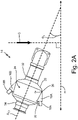
- FIG. 1 is a perspective view of air conditioning pack (“ACP") 10 and shows condenser 12, water extractor 14 (with pocket 16 and boss 18), air cycle machine 20, heat exchanger 22, and direction G of gravity.
- ACP 10 is an air conditioning pack suitable for an aircraft.
- Condenser 12 is a condenser heat exchanger configured to remove water from a flow of air passing through or across condenser 12.
- Water extractor 14 is a device configured to remove condensate from a flow of fluid through water extractor 14.
- water extractor 14 is configured as an inertial particle separator for fluids.
- water extractor 14 and the elements of water extractor 14 can be manufactured through layer-by-layer additive manufacturing, injection molding, fabrication, or other manufacturing techniques.
- a material of water extractor 14 and/or pocket 16 and boss 18 can include metal such as aluminum, plastic, thermoplastic such as carbon-fiber-reinforced polyether ether ketone, or another solid material suitable for passage of a fluid with a temperature of 32° to 500° F (0° to 260° C).
- Pocket 16 is a curved piece of solid material that forms a horizontal basin.
- Boss 18 is an outlet configured for transmission of a fluid.
- ACM 20 is an air cycle machine of an aircraft.
- heat exchanger 22 is a dual heat exchanger configured to transfer heat to or from a fluid (e.g., air) that passes through heat exchanger 22.
- Direction G is representative of a direction of gravity when the aircraft containing ACP 10 is on the ground or in horizontal flight.
- ACP 10 can be fluidly connected to an intermediate or high pressure stage of a gas turbine engine.
- ACP 10 is shown as including a single ACM 20, in other non-limiting embodiments ACP 10 can include a multi-ACM configuration such as a first ACM and a second ACM with first and second cooling inlets, respectively and a first water extractor and a second water extractor connected to the first and second cooling inlets, respectively.
- condenser 12 is connected to heat exchanger 22.
- Condenser 12 is attached and fluidly connected to water extractor 14.
- Water extractor 14 is attached to condenser 12 and is fluidly connected to condenser 12 and ACM 20.
- Pocket 16 is mounted to a portion of water extractor 14.
- water extractor 14 is shown as including one pocket 16 with one boss 18.
- water extractor 14 can include two or more pockets 16 with corresponding bosses 18.
- Boss 18 is attached and connected to pocket 16.
- Boss 18 is fluidly connected to water extractor 14 via pocket 16.
- ACM 20 is fluidly connected to water extractor 14.
- Heat exchanger 22 is mounted within ACP 10 and is fluidly connected to condenser 12.
- boss 18 would be capped and not in use given the orientation of ACP 10 relative to gravity depicted in FIG. 1 .
- Aircraft e.g., commercial aircraft are typically equipped with one or more ACPs 10 that provide pressurized, conditioned air to the cockpit and passenger cabin of the aircraft.
- ACP 10 is supplied with high pressure, hot air either from engines or from electrically driven compressors of the aircraft.
- ACP 10 uses ACM 20 with turbines to cool the supplied air down to freezing temperatures. Upstream of ACM 20, water extractor 14 receives air from condenser 12 and is used to extract any condensed moisture before the moisture enters ACM 20 and freezes on the turbine blades. Water freezing on the turbine blades could cause premature failure of ACM 20 resulting in an in-flight failure of ACM 10. Additional details of ACPs can be found in United States Patent 7,188,488 , which is herein incorporated by reference in its entirety. Additional details of ACMs can be found in United States Patent Application Serial No. 14/180,777 filed on February 14, 2014 , which is herein incorporated by reference in its entirety.
- ACP 10 may be required to be positioned at an angle respective to direction G of gravity, which may require water extractor 14 to also be positioned at an angle respective to a horizontal plane such that an inlet of water extractor 14 is lower than an outlet of water extractor 14. Such an angle with respect to horizontal can reduce water extraction efficiency of water extractor 14 and potentially cause failure of ACM 10 if the water collected by water extractor 14 is not removed from water extractor 14 at a high enough efficiency rate.
- water extractor 14 with pocket 16 and boss 18 enables water extractor 14 to be positioned at an angle with respect to horizontal while maintaining a requisite efficiency of water extractor 14 due to the horizontal placements of pocket 16 and boss 18.
- FIG. 2A is a side view of water extractor 14 and shows pockets 16A and 16B, bosses 18A and 18B, body 24 (with outer wall 26, upstream portion 28, and downstream portion 30), inlet 32, outlet 34, first centerline axis A C1 , direction G of gravity, horizontal plane H, and first angle ⁇ 1 .
- FIG. 2B is a top view of water extractor 14 and shows pocket 16B, boss 18B, and body 24 (with outer wall 26, upstream portion 28, and downstream portion 30), inlet 32, and outlet 34.
- FIGS 2A and 2B include the same or similar elements and will be discussed in unison.
- Body 24 is an enlarged, central portion of water extractor 14.
- Outer wall 26 is a cylindrical barrier of solid material.
- Upstream portion 28 is a portion of body 24 that is located on an upstream end (to the right in FIGS. 2A and 2B ) of body 24.
- Downstream portion 30 is a portion of body 24 that is located on a downstream end (to the left in FIGS. 2A and 2B ) of body 24.
- Inlet 32 and outlet 34 are tubes of solid material that are configured to transport a fluid.
- First centerline axis A C1 is an axis extending longitudinally through a center of water extractor 14.
- Direction G is a direction of gravity relative to ACP 10 (shown in FIG. 1 ) and water extractor 14.
- Horizontal plane H is a plane that is representative of the horizontal direction when the aircraft containing ACP 10 is on the ground or in horizontal flight.
- horizontal plane H is orientated at a 90 degree angle with respect to direction G of gravity.
- First angle ⁇ 1 is an angle between first centerline axis A C1 and horizontal plane H.
- First angle ⁇ 1 is an angle of inclination with respect to horizontal plane H.
- Pocket 16A is mounted to a portion of body 24 and pocket 16B is mounted to another portion of body 24.
- pocket 16A is mounted to a bottom portion of body 24 (a bottom of body 24 as shown in FIG. 2A ) and pocket 16B is mounted to a top portion of body 24 (the top of body 24 as shown in FIG. 2A ).
- Boss 18A extends from and is fluidly connected to pocket 16A.
- Boss 18B extends from and is fluidly connected to pocket 16B.
- Boss 18A is fluidly connected to body 24 via pocket 16A and boss 18B is fluidly connected to body 24 via pocket 16B.
- Body 24 is co-axial with first centerline axis A C1 and is disposed between inlet 32 and outlet 34.
- Body 24 is fluidly connected to inlet 32 and to outlet 34.
- Outer wall 26 extends around a circumference of body 24.
- Upstream portion 28 of body 24 is connected to downstream portion 30.
- Downstream portion 30 of body 24 is positioned downstream of upstream portion 28 relative to a direction of a flow of fluid through water extractor 14, which as shown in FIGS. 2A and 2B as right to left (and slightly upwards).
- Inlet 32 and outlet 34 are attached and fluidly connected to body 24.
- First centerline axis A C1 passes through centers of body 24, inlet 32, and outlet 34 of water extractor 14.
- Direction G of gravity points in a downward direction in FIG. 2A .
- first angle ⁇ 1 is greater than zero degrees meaning that outlet 34 is higher than inlet 32. In one non-limiting embodiment, first angle ⁇ 1 can be 10 degrees to 55 degrees.
- water extractor 14 functions by centrifuging a flow of air passing through water extractor 14 so as to drawn moisture in the flow of air radially outward and into an outer portion of body 24 where the moisture is collected by pocket 16A or pocket 16B.
- Pockets 16A and 16B both include a curved cavity in which moisture is collected and through which the moisture is communicated to bosses 18A and 18B, respectively.
- Bosses 18A and 18B are used to remove collected moisture from pockets 16A and 16B, respectively. In one non-limiting embodiment, only one set of pocket 16A and boss 18A or pocket 16B and boss 18B are used during operation of ACP 10.
- boss 18A would be used to extract water and boss 18b would be capped and not in use given the orientation of ACP 10 relative to gravity depicted in FIG. 2A .
- Body 24 fluidly contains a portion of a flow of air that passes through water extractor 14. As will be discussed further with respect to FIGS. 3A and 3B , moisture in the flow of air passed through water extractor 14 is sent through an outer portion of body 24 so as to be extracted from the flow of air.
- Outer wall 26 contains the flow of air through body 24.
- Upstream portion 28 of body 24 directs a portion of the flow through water extractor 14 into body 24.
- Downstream portion 30 of body 24 directs a portion of the flow within body 24 to outlet 34.
- Inlet 32 receives a flow of air and delivers that air to body 24.
- Outlet 34 receives the flow of air from body 24 and delivers the flow of air out of water extractor 14.
- Water extractor 14 with pocket 16 and boss 18 allows water extractor 14 to be installed in a non-horizontal orientation with no loss of efficiency by providing boss 18 that is located at a low point, or gravitational bottom, of body 24 so as to collect the greatest amount of moisture from body 24.
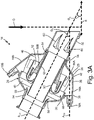
- FIG. 3A is a cross-section view of water extractor 14 taken along 3-3 in FIG. 2B and shows water extractor 14, pocket 16A (with upstream portion 36 and downstream portion 38), pocket 16B, boss 18A, boss 18B, body 24 (with outer wall 26, upstream portion 28, downstream portion 30, gravitational bottom 42, outer chamber 44 (including upstream end 46 and downstream end 48), inner nozzle 50, and serpentine channel 52), annular gap 54, flow guides 56A and 56B, ejector 58, inlet 32 (with vanes 60), outlet 34, first centerline axis A C1 , second centerline axis A C2 , first angle ⁇ 1 , second angle ⁇ 2 , direction G of gravity, and horizontal plane H.
- FIG. 1 is a cross-section view of water extractor 14 taken along 3-3 in FIG. 2B and shows water extractor 14, pocket 16A (with upstream portion 36 and downstream portion 38), pocket 16B, boss 18A, boss 18B, body 24 (with outer wall 26, upstream portion 28, downstream portion 30, gravitation
- FIG. 3B is a cross-section view of water extractor 14 taken along 3-3 in FIG. 2B and shows water extractor 14, pocket 16A, pocket 16B, boss 18A, boss 18B, body 24 (with outer wall 26, gravitational bottom 42, outer chamber 44, inner nozzle 50, and serpentine channel 52), annular gap 54, flow guides 56A and 56B, ejector 58, inlet 32 (with vanes 60), outlet 34, first centerline axis A C1 , initial flow F A , primary flow F 1 , secondary flow F 2 , resultant flow F R , flow F W , and direction G of gravity.
- FIGS. 3A and 3B include the same or similar elements and will generally be discussed in unison.
- a flow of fluid flows through water extractor 14 from the right side or end of water extractor as shown in FIGS. 3A and 3B to the left side or end of water extractor as shown in FIGS. 3A and 3B .
- the term downstream will generally refer to the left end of water extractor 14 as shown in FIGS. 3A and 3B (for example, the end of water extractor 14 where outlet 34 is located).
- the term upstream will generally refer to the right end of water extractor 14 as shown in FIGS. 3A and 3B (for example, the end of water extractor 14 where inlet 32 is located).
- downstream direction will refer to a direction that is right to left as shown in FIGS. 3A and 3B and is generally aligned with first centerline axis A C1 .
- upstream direction will refer to a direction that is left to right as shown in FIGS. 3A and 3B and is generally aligned with first centerline axis A C1 .
- Vanes 60 are fins or blades for imparting swirl or spin on a fluid which passes across vanes 60.
- Second centerline axis A C2 is an axis extending longitudinally through a center of boss 18A.
- Second angle ⁇ 2 is an angle extending between second centerline axis A C2 and first centerline axis A C1 .
- Second angle ⁇ 2 is an angle of declination of second centerline axis A C2 with respect to first centerline axis A C1 .
- second centerline axis A C2 is approximately perpendicular to direction G of gravity and approximately parallel to horizontal plane H.
- Initial flow F A is a flow of cooling air coming from condenser 12 (shown in FIG. 1 ).
- Primary flow F 1 is a flow of air flowing through inner nozzle 50.
- Secondary flow F 2 is a flow of fluid passing through outer chamber 44.
- Secondary flow F 2 is a flow of moisture-laden air.
- Resultant flow F R is a combined flow of air including primary flow F 1 and secondary flow F 2 .
- flow F W is a flow of water.
- flow F W can include part liquid water and part moisture-laden air.
- Pocket 16A is disposed along and on a bottom of body 24 between inlet 32 and outlet 34.
- pocket 16A is attached and connected to gravitational bottom 42 of body 24.
- Pocket 16A is fluidly connected to outer chamber 44 at gravitational bottom 42 of body 24.
- Pockets 16A and 16B are configured to collect water from secondary flow F 2 passing through outer chamber 44.
- Boss 18A extends from pocket 16A and is fluidly connected to pocket 16A.
- Boss 18B extends from pocket 16B and is fluidly connected to pocket 16B.
- Second centerline axis A C2 of boss 18A intersects with first centerline axis A C1 of water extractor 14 at second angle ⁇ 2 .
- the second angle ⁇ 2 is 10 to 45 degrees.
- second angle ⁇ 2 is approximately 26 degrees. In this non-limiting embodiment, second angle ⁇ 2 is greater than or equal to first angle ⁇ 1 . In this non-limiting embodiment, second centerline axis A C2 of boss 18 is perpendicular to direction G of gravity and parallel to horizontal plane H.
- Body 24 of water extractor 14 is attached and is fluidly connected to inlet 32 and outlet 34.
- Outer wall 30 is an exterior of body 24. Outer wall 30 surrounds and encloses outer chamber 44.
- Inlet 32 is fluidly connected to inner nozzle 50 and to outer chamber 44 via serpentine channel 52.
- Inlet 32 is disposed on upstream portion 28 of body 24.
- Outlet 34 is an opening of body 24.
- Outlet 34 is fluidly connected to inner nozzle 50 and to outer chamber 44 via ejector 58.
- Outlet 34 is disposed on downstream portion 30 of body 24.
- Upstream portion 28 is disposed downstream along first centerline axis A C1 relative to inlet 32.
- Downstream portion 30 is disposed upstream along first centerline axis A C1 relative to outlet 34.
- Gravitational bottom 42 is disposed at a bottom-most portion of body 24 relative to the orientation shown in FIGS. 3A and 3B . Being that direction G of gravity is shown as straight down in FIGS. 3A and 3B , gravitational bottom 42 of body 24 is located on the point of body 24 that is furthest downward portion of body 24.
- Outer chamber 44 is disposed in a radially outer portion of body 24. Outer chamber 44 is fluidly connected to pockets 16A and 16B, to bosses 18A and 18B via pockets 16A and 16B, to inlet 32 via serpentine channel 52, and to outlet 34. Outer chamber 44 is encased, or contained, by outer wall 26. Outer chamber 44 extends between outer wall 26 and inner nozzle 50. Upstream end 46 of outer chamber 44 is disposed in downstream portion 30 and is fluidly connected to serpentine channel 52. Downstream end 48 of outer chamber 44 is disposed in upstream portion 28 of body 24 and is fluidly connected to outlet 34. Inner nozzle 50 is disposed radially within outer wall 26 and is physically connected to outer wall 30 via trusses or other physical attachments.
- Inner nozzle 50 is fluidly connected to inlet 32 by way of an upstream end of inner nozzle 50 being disposed in or adjacent to a portion of inlet 32.
- Inner nozzle 50 is fluidly connected to outlet 34 by way of a downstream end of inner nozzle 50 being disposed in or adjacent to a portion of outlet 34.
- Inner nozzle 50 is co-axial with first centerline axis A C1 .
- Serpentine channel 52 is fluidly connected to outer chamber 44 and to inlet 32.
- Serpentine channel 52 is disposed radially between outer wall 26 of body 24 and inner nozzle 50.
- Serpentine channel 52 is disposed radially outwards from and circumferentially surrounds inner nozzle 50.
- Serpentine channel 52 is formed by portions of inner nozzle 50, flow guides 56A and 56B, and outer wall 26.
- Serpentine channel 52 is configured to guide a direction of flow passing through serpentine channel 52 from a downstream direction of water extractor 14, to an upstream direction of water extractor 14, and back to the downstream direction of water extractor 14.
- Annular gap 54 is fluidly connected to inlet 32 and circumferentially extends around an upstream end of inner nozzle 50.
- Annular gap 54 is disposed radially between inner nozzle 50 and a portion of serpentine channel 52.
- Flow guides 56A and 56B are disposed radially outward from inner nozzle 50.
- Flow guides 56A and 56B form contours and edges of serpentine channel 52.
- Ejector 58 is fluidly connected to outer chamber 44 and is disposed radially outward from inner nozzle 50.
- Ejector 58 is disposed radially outward from inner nozzle 50 and radially inward from a portion of outer wall 26 that is near outlet 34.
- Vanes 60 are connected to or formed together with inlet 32. Vanes 60 are disposed along an internal (e.g., radially inward) surface of a portion of inlet 32. Vanes 60 extend radially inward from an internal surface of inlet 32 and in a direction that is off-axis from a main flow direction of inlet 32 such that vanes 60 are configured to impart swirl upon a fluid, such as cooling flow of air, that passes across vanes 60.
- second angle ⁇ 2 is greater than zero, and can include an angle of 10 degrees to 90 degrees, such as an angle of 25 degrees as shown in FIGS. 3A and 3B . Second centerline axis A C2 is oriented approximately perpendicular to direction G of gravity and approximately parallel to horizontal plane H.
- a cooling flow of air is sent from condenser 12 (shown in FIG. 1 ) to water extractor 14.
- the cooling flow of air enters water extractor 14 via inlet 32.
- vanes 60 swirl initial flow F A in order to cause moisture in initial flow F A to move in a radially outward direction.
- a bend in a duct position upstream from inlet 32 can be configured to swirl initial flow F A before initial flow F A enters into water extractor 14. Since the cooling flow of air is swirling as the cooling flow of air enters body 24, moisture in the cooling flow of air is forced centrifugally in a radially outwards direction.
- the cooling flow of air is split into primary flow F 1 and secondary flow F 2 within water extractor 14.
- secondary flow F 2 is diverted through serpentine channel 52 and into outer chamber 44, while first flow F 1 is drawn into and through inner nozzle 50.
- second flow F 2 entering serpentine channel 52 contains a high amount of moisture due to serpentine channel 52 being positioned radially outwards of inner nozzle 50.
- a rate of flow of secondary flow F 2 reduces in response to an increased effective flow area of outer chamber 44.
- moisture from secondary flow F 2 is deposited in the form of moisture droplets onto an inner surface of outer wall 26.
- the moisture droplets deposited onto outer wall 26 are then drawn in a downwards direction due to gravity and are received by pocket 16A.
- moisture or water
- water is received from secondary flow F 2 into pocket 16 by withdrawing water from secondary flow F 2 from upstream end 46 of outer chamber 44.
- water is received from secondary flow F 2 into pocket 16 by withdrawing water from secondary flow F 2 at gravitational bottom 42 of body 24.
- secondary flow F 2 enters annular gap 54 at the same velocity as primary flow F 1 enters inner nozzle 50.
- a volume, or cross-sectional area, of serpentine channel 52 increases rapidly as serpentine channel 52 extends from annular gap 54 to outer chamber 44. This increase in cross-sectional area and/or volume of serpentine channel 52 results in a sudden reduction in velocity of secondary flow F 2 in serpentine channel 52. As such, the suspended water droplets fall out of secondary flow F 2 due to the reduction in velocity and attach to outer wall 26. The water then runs down outer wall 26 to collect in pocket 16A and to exit through boss 18A.
- flow F W communicated through boss 18A can include both liquid water and moisture-laden air.
- secondary flow F 2 continues through outer chamber 44, passes through ejector 58, and is combined with primary flow F 1 flowing through inner nozzle 50.
- Secondary flow F 2 passes through ejector 58, most or all of the moisture has been removed from secondary flow F 2 .
- Primary flow F 1 flowing through inner nozzle 50 contains a higher velocity than secondary flow F 2 coming out of outer chamber 44 which creates a pressure differential to draw or pull secondary flow F 2 out of outer chamber 44 and through ejector 58.
- secondary flow F 2 After secondary flow F 2 passes through ejector 58, secondary flow F 2 enters outlet 34 along with primary flow F 1 . Primary flow F 1 and secondary flow F 2 are rejoined after removing water from secondary flow F 2 to form resultant flow F R of air.
- Resultant flow F R of air is then sent to ACM 20 (shown in FIG. 1 ) that is fluidly connected to water extractor 14.
- pocket 16A By locating pocket 16A at gravitational bottom 42 of body 24, pocket 16A (and therefore boss 18A) is located at a low point of body 24. With pocket 16A being located at the low point of body 24, all of the moisture collected in body 24 gathers into pocket 16A as the moisture drains out of body 24.
- Pocket 16A (and boss 18A) are also located in an ideal flow velocity area of outer chamber 44.
- the ideal flow velocity area of outer chamber 44 is located in the portion of outer chamber 44 where secondary flow F 2 makes its final turn from and out of serpentine channel 52 and into outer chamber 44. At this location, secondary flow F 2 is travelling in generally the same downstream direction as a direction of primary flow F 1 through inner nozzle 50. This portion of secondary flow F 2 does not need to undergo a drastic change in direction to enter into boss 18A via pocket 16A because boss 18A extends generally in a similar direction as the direction of secondary flow F 2 through outer chamber 44. Having pocket 16A being located at the ideal flow velocity area of outer chamber 44 allows the maximum amount of moisture to be removed from secondary flow F 2 to enter into boss 18A via pocket 16A which maximizes the efficiency of water extractor 14.
- Water extractor 14 with pocket 16A and boss 18A allows water extractor 14 to be installed in a non-horizontal orientation with no loss of efficiency by providing pocket 16A (and boss 18A) that is located in the ideal flow velocity area of outer chamber 44 of body 24. Water extractor 14 with pocket 16A and boss 18A provide for increases in efficiency of water extraction from existing amounts near 85% up to new efficiency rates of 95% or greater. Water extractor 14 provides a relatively low cost design change that will allow off-the-shelf ACPs to be installed in non-horizontal angles as needed by individual engine requirements.
Claims (6)
- Procédé d'extraction d'eau d'un flux d'air, le procédé comprenant :le tourbillonnement du flux d'air ;l'insertion du flux d'air dans un extracteur d'eau, dans lequel l'extracteur d'eau comporte un premier axe central passant par un centre de l'extracteur d'eau le long d'une direction longitudinale de l'extracteur d'eau ;la division du flux d'air en un flux principal et un flux secondaire à l'intérieur de l'extracteur d'eau ;le détournement du flux secondaire dans une chambre extérieure de l'extracteur d'eau, dans lequel la chambre extérieure est disposée entre une buse intérieure et une paroi extérieure d'un corps de l'extracteur d'eau ;la réception de l'eau séparée du flux secondaire dans une poche reliée fluidiquement à la chambre extérieure et fixée à la paroi extérieure du corps de l'extracteur d'eau ;la communication de l'eau reçue par la poche dans un bossage relié à la poche ; etl'extraction de l'eau du bossage, dans lequel le bossage comporte un second axe central passant par un centre du bossage, dans lequel le second axe central est à un certain angle par rapport au premier axe central qui est supérieur à zéro degré, et dans lequel le second axe central est orienté parallèlement à un plan horizontal, le plan horizontal (H) étant un plan représentatif de la direction horizontale lorsque l'aéronef contenant un pack de climatisation (10) avec l'extracteur d'eau est au sol ou en vol horizontal, et dans lequel l'angle entre les premier et second axes centraux va de 10 à 45 degrés ; etdans lequel la réception d'eau du flux secondaire dans la poche comprend en outre le retrait d'eau du flux secondaire au niveau d'un fond gravitationnel du corps ; etdans lequel un second angle entre le premier axe central et un plan horizontal est supérieur à zéro degré.
- Procédé selon la revendication 1, comprenant en outre :l'envoi du flux d'air d'un condenseur d'un pack de climatisation à l'extracteur d'eau ;la réunion du flux principal et du flux secondaire dans une sortie de l'extracteur d'eau après avoir retiré l'eau du flux secondaire pour former un flux d'air résultant ; etl'envoi du flux d'air résultant à un groupe turbo-refroidisseur qui est relié fluidiquement à l'extracteur d'eau.
- Pack de climatisation pour aéronef, le pack de climatisation comprenant :un condenseur (12) ;un groupe turbo-refroidisseur (20) en communication fluidique avec le condenseur ; etun extracteur d'eau (14) reliant fluidiquement le condenseur au groupe turbo-refroidisseur, l'extracteur d'eau comprenant :un corps (24) avec une paroi extérieure (26), dans lequel la paroi extérieure comprend une partie amont (28) et une partie aval (30) ;une buse intérieure (50) disposée radialement vers l'intérieur à partir de la paroi extérieure, dans lequel les parties amont et aval de la paroi extérieure sont orientées par rapport à une direction d'un écoulement de fluide à travers la buse intérieure ;une entrée (32) disposée sur une extrémité amont du corps et reliée fluidiquement au condenseur ;une sortie (34) disposée sur une extrémité aval du corps et reliée fluidiquement au groupe turbo-refroidisseur ;une chambre extérieure (44) disposée dans le corps et s'étendant entre la paroi extérieure et la buse intérieure, dans lequel la chambre extérieure est reliée fluidiquement avec l'entrée et la sortie, dans lequel la chambre extérieure comprend une partie amont (46) et une partie aval (48), dans lequel la chambre extérieure est configurée pour recevoir un flux d'air chargé d'humidité depuis l'entrée, et dans lequel la chambre extérieure est configurée pour déposer l'humidité provenant du flux d'air chargé d'humidité sur la paroi extérieure ;une poche (16) reliée à la paroi extérieure du corps, dans lequel la poche comprend une partie amont (36) et une partie aval (38), dans lequel la partie amont de la poche est fixée à la partie amont de la paroi extérieure et est reliée fluidiquement à la partie amont de la chambre extérieure, et dans lequel la poche est configurée pour collecter l'humidité déposée depuis la paroi extérieure ; etun bossage (18) s'étendant depuis la poche, dans lequel le bossage est relié fluidiquement à la partie amont de la chambre extérieure via la poche, dans lequel le bossage est configuré pour extraire l'humidité collectée de la poche ; caractérisé en ce que l'extracteur d'eau comprend en outre un premier axe central (AC1) passant par un centre de la buse intérieure, dans lequel le bossage comprend en outre un second axe central (AC2) passant par un centre du bossage, dans lequel le second axe central est à un certain angle par rapport au premier axe central qui est supérieur à zéro degré, et dans lequel le second axe central est orienté parallèlement à un plan horizontal, le plan horizontal (H) étant un plan représentatif de la direction horizontale lorsque l'aéronef contenant un pack de climatisation (10) avec l'extracteur d'eau est au sol ou en vol horizontal, et dans lequel l'angle entre les premier et second axes centraux va de 10 à 45 degrés ;dans lequel une partie de la poche est reliée à un emplacement de la paroi extérieure du corps qui est au niveau d'un fond gravitationnel (42) de la paroi extérieure du corps ; etdans lequel un angle entre le premier axe central et le plan horizontal est supérieur ou égal à environ 10 degrés.
- Pack de climatisation selon la revendication 3, dans lequel l'extracteur d'eau est configuré comme un séparateur inertiel de particules.
- Pack de climatisation selon l'une quelconque des revendications 3 et 4, comprenant en outre :un canal sinueux (52) disposé radialement entre la buse intérieure et la chambre extérieure ; etun espace annulaire (54) disposé entre le canal sinueux et la buse intérieure, dans lequel l'espace annulaire relie fluidiquement le canal sinueux et l'entrée.
- Pack de climatisation selon la revendication 5, dans lequel le canal sinueux est disposé radialement vers l'extérieur depuis et entoure circonférentiellement la buse intérieure, et dans lequel le canal sinueux est en outre configuré pour guider une direction d'écoulement traversant le canal sinueux depuis une direction aval, vers une directement amont, et à nouveau vers une direction aval.
Applications Claiming Priority (1)
| Application Number | Priority Date | Filing Date | Title |
|---|---|---|---|
| US15/918,733 US10633099B2 (en) | 2018-03-12 | 2018-03-12 | Non-horizontal water extractor |
Publications (2)
| Publication Number | Publication Date |
|---|---|
| EP3539635A1 EP3539635A1 (fr) | 2019-09-18 |
| EP3539635B1 true EP3539635B1 (fr) | 2022-09-21 |
Family
ID=65818182
Family Applications (1)
| Application Number | Title | Priority Date | Filing Date |
|---|---|---|---|
| EP19162339.6A Active EP3539635B1 (fr) | 2018-03-12 | 2019-03-12 | Extracteur d'eau non horizontal |
Country Status (2)
| Country | Link |
|---|---|
| US (1) | US10633099B2 (fr) |
| EP (1) | EP3539635B1 (fr) |
Families Citing this family (6)
| Publication number | Priority date | Publication date | Assignee | Title |
|---|---|---|---|---|
| US11154804B2 (en) | 2018-12-07 | 2021-10-26 | Hamilton Sundstrand Corporation | Water extractors and methods of making water extractors |
| EP3944888A1 (fr) | 2020-07-29 | 2022-02-02 | Hamilton Sundstrand Corporation | Collecteur d'eau annulaire à haute pression comprenant des ailettes de tourbillonnement axiales pour un système de commande environnemental à cycle d'air |
| US11802736B2 (en) | 2020-07-29 | 2023-10-31 | Hamilton Sundstrand Corporation | Annular heat exchanger |
| IT202100015587A1 (it) * | 2021-06-15 | 2022-12-15 | Alfonso Sacco | Velivolo includente un sistema e procedimento di stoccaggio di acqua prelevata dall’ambiente atmosferico |
| US20220411073A1 (en) * | 2021-06-29 | 2022-12-29 | Hamilton Sundstrand Corporation | Centrifugal water collector with conical water scupper |
| US20230347270A1 (en) * | 2022-04-29 | 2023-11-02 | Hamilton Sundstrand Corporation | Mid-pressure water collector (mpwc) with helical flow channel and radial scuppers |
Citations (1)
| Publication number | Priority date | Publication date | Assignee | Title |
|---|---|---|---|---|
| WO2008034681A1 (fr) * | 2006-09-19 | 2008-03-27 | Alstom Technology Ltd | Séparateur d'eau pour installation de turbine à vapeur |
Family Cites Families (28)
| Publication number | Priority date | Publication date | Assignee | Title |
|---|---|---|---|---|
| GB800932A (en) | 1953-06-19 | 1958-09-03 | Sir George Godfrey And Partner | Improvements in or relating to the extraction of liquid, such as water, from air or other gases |
| US3339349A (en) | 1964-08-28 | 1967-09-05 | United Aircraft Corp | Coalescer |
| US3834126A (en) | 1973-01-26 | 1974-09-10 | United Aircraft Corp | Water separator |
| US4224043A (en) | 1978-04-20 | 1980-09-23 | Nfe International, Ltd. | Compact multistage particle separator |
| US4238210A (en) | 1979-04-26 | 1980-12-09 | Siegfried Bulang | Particle-removal apparatus |
| US4681610A (en) * | 1986-02-13 | 1987-07-21 | United Technologies Corporation | High performance water collector |
| FR2642662B1 (fr) | 1989-02-09 | 1992-04-30 | Abg Semca | Dispositif et procede de separation des particules solides presentes dans un gaz et appareil comportant un tel dispositif |
| JP2578964Y2 (ja) | 1993-06-07 | 1998-08-20 | 三菱重工業株式会社 | 波板式気水分離器 |
| JP3857729B2 (ja) | 1996-02-02 | 2006-12-13 | ポール・コーポレーション | 煤フィルタ |
| US6056798A (en) | 1998-05-04 | 2000-05-02 | Air Equipment & Engineering,Inc. | Multi stage separator |
| WO1999059867A1 (fr) | 1998-05-20 | 1999-11-25 | Alliedsignal Inc. | Extracteur d'eau a effet coanda |
| US6524373B2 (en) * | 2000-07-28 | 2003-02-25 | Honeywell International Inc. | Two-stage water extractor |
| US7188488B2 (en) | 2003-03-12 | 2007-03-13 | Hamilton Sundstrand | Pack and a half condensing cycle pack with combined heat exchangers |
| EP1680205A4 (fr) | 2003-08-26 | 2007-07-04 | Hydrogenics Corp | Appareil pour separer un liquide contenu dans un flux de gaz de procede d'un empilement de cellules electrochimiques |
| DE102004036568A1 (de) * | 2004-07-28 | 2006-02-16 | Liebherr-Aerospace Lindenberg Gmbh | Wasserabscheider für Klimaanlagen |
| US7342332B2 (en) | 2004-09-22 | 2008-03-11 | Hamilton Sundstrand Corporation | Air bearing and motor cooling |
| US7470300B2 (en) * | 2005-12-07 | 2008-12-30 | Honeywell International Inc. | Duct wall water extractor |
| US7691185B2 (en) * | 2006-12-14 | 2010-04-06 | Honeywell International Inc. | Recirculating Coanda water extractor |
| US10286407B2 (en) | 2007-11-29 | 2019-05-14 | General Electric Company | Inertial separator |
| US8177475B2 (en) | 2008-05-02 | 2012-05-15 | Honeywell International, Inc. | Contaminant-deflector labyrinth seal and method of operation |
| US8875535B2 (en) * | 2009-12-02 | 2014-11-04 | Hamilton Sundstrand Corporation | Compact condenser module including a tortuous path for removing water droplets from air |
| US8454716B2 (en) | 2011-03-17 | 2013-06-04 | Siemens Energy, Inc. | Variable flow particle separating structure |
| JP5803639B2 (ja) | 2011-12-08 | 2015-11-04 | 株式会社島津製作所 | 水分離器 |
| KR101606489B1 (ko) | 2013-04-15 | 2016-03-25 | 정현욱 | 공기 순환 장치 및 필터 조립체 |
| US9199248B2 (en) | 2013-10-01 | 2015-12-01 | Honeywell International Inc. | Aircraft electronic particle separation system |
| US20150233386A1 (en) | 2014-02-14 | 2015-08-20 | Hamilton Sundstrand Corporation | First stage turbine housing for an air cycle machine |
| US10118116B2 (en) | 2015-01-07 | 2018-11-06 | Hyun-Wook Jeong | Moisture separator and air cycle system with the same |
| US9897093B2 (en) | 2015-03-25 | 2018-02-20 | Hamilton Sundstrand Corporation | Bearing cooling flow and energy recovery systems |
-
2018
- 2018-03-12 US US15/918,733 patent/US10633099B2/en active Active
-
2019
- 2019-03-12 EP EP19162339.6A patent/EP3539635B1/fr active Active
Patent Citations (1)
| Publication number | Priority date | Publication date | Assignee | Title |
|---|---|---|---|---|
| WO2008034681A1 (fr) * | 2006-09-19 | 2008-03-27 | Alstom Technology Ltd | Séparateur d'eau pour installation de turbine à vapeur |
Also Published As
| Publication number | Publication date |
|---|---|
| EP3539635A1 (fr) | 2019-09-18 |
| US20190276155A1 (en) | 2019-09-12 |
| US10633099B2 (en) | 2020-04-28 |
Similar Documents
| Publication | Publication Date | Title |
|---|---|---|
| EP3539635B1 (fr) | Extracteur d'eau non horizontal | |
| US7691185B2 (en) | Recirculating Coanda water extractor | |
| US7591869B2 (en) | Apparatus and method for extracting condensate | |
| EP1305101B1 (fr) | Extracteur d'eau bi-etage | |
| EP3427809B1 (fr) | Extracteur d'eau | |
| EP2617648B1 (fr) | Séparateur de particules carénées | |
| US11839846B2 (en) | High-pressure annular water collector with axial swirl vanes for an air cycle environmental control system | |
| EP3339175B1 (fr) | Circuit de refroidissement de moteur avec séparateur de particules de dommage par corps étranger | |
| EP3586938B1 (fr) | Extracteur d'eau hélicoïdal | |
| US10852078B2 (en) | Droplet heat exchange systems and methods | |
| EP3427812B1 (fr) | Appareil d'extraction d'eau pour système de contrôle d'environnement d'aéronef | |
| EP3412354A1 (fr) | Séparateur d'eau d'entrée tangentielle pour systèmes de contrôle de l'environnement (ecs) d'aéronef | |
| CN107031848A (zh) | 低压包 | |
| EP3662984B1 (fr) | Extracteurs d'eau et procédés de fabrication d'extracteurs d'eau | |
| EP2799124B1 (fr) | Séparateur de particules | |
| US11577181B2 (en) | Forward secant swirl tube | |
| EP4147765A1 (fr) | Séparateur d'eau à pression moyenne intégré | |
| CN113260792B (zh) | 喷射式风机和包含这种风机的运输工具 |
Legal Events
| Date | Code | Title | Description |
|---|---|---|---|
| PUAI | Public reference made under article 153(3) epc to a published international application that has entered the european phase |
Free format text: ORIGINAL CODE: 0009012 |
|
| STAA | Information on the status of an ep patent application or granted ep patent |
Free format text: STATUS: THE APPLICATION HAS BEEN PUBLISHED |
|
| AK | Designated contracting states |
Kind code of ref document: A1 Designated state(s): AL AT BE BG CH CY CZ DE DK EE ES FI FR GB GR HR HU IE IS IT LI LT LU LV MC MK MT NL NO PL PT RO RS SE SI SK SM TR |
|
| AX | Request for extension of the european patent |
Extension state: BA ME |
|
| STAA | Information on the status of an ep patent application or granted ep patent |
Free format text: STATUS: REQUEST FOR EXAMINATION WAS MADE |
|
| 17P | Request for examination filed |
Effective date: 20191120 |
|
| RBV | Designated contracting states (corrected) |
Designated state(s): AL AT BE BG CH CY CZ DE DK EE ES FI FR GB GR HR HU IE IS IT LI LT LU LV MC MK MT NL NO PL PT RO RS SE SI SK SM TR |
|
| STAA | Information on the status of an ep patent application or granted ep patent |
Free format text: STATUS: EXAMINATION IS IN PROGRESS |
|
| 17Q | First examination report despatched |
Effective date: 20201022 |
|
| GRAP | Despatch of communication of intention to grant a patent |
Free format text: ORIGINAL CODE: EPIDOSNIGR1 |
|
| STAA | Information on the status of an ep patent application or granted ep patent |
Free format text: STATUS: GRANT OF PATENT IS INTENDED |
|
| INTG | Intention to grant announced |
Effective date: 20220413 |
|
| RIN1 | Information on inventor provided before grant (corrected) |
Inventor name: MCCORD, PATRICK Inventor name: LOKHANDWALLA, MURTUZA Inventor name: WALSH, KEVIN P. |
|
| GRAS | Grant fee paid |
Free format text: ORIGINAL CODE: EPIDOSNIGR3 |
|
| GRAA | (expected) grant |
Free format text: ORIGINAL CODE: 0009210 |
|
| STAA | Information on the status of an ep patent application or granted ep patent |
Free format text: STATUS: THE PATENT HAS BEEN GRANTED |
|
| AK | Designated contracting states |
Kind code of ref document: B1 Designated state(s): AL AT BE BG CH CY CZ DE DK EE ES FI FR GB GR HR HU IE IS IT LI LT LU LV MC MK MT NL NO PL PT RO RS SE SI SK SM TR |
|
| REG | Reference to a national code |
Ref country code: GB Ref legal event code: FG4D |
|
| REG | Reference to a national code |
Ref country code: CH Ref legal event code: EP |
|
| REG | Reference to a national code |
Ref country code: DE Ref legal event code: R096 Ref document number: 602019019714 Country of ref document: DE |
|
| REG | Reference to a national code |
Ref country code: IE Ref legal event code: FG4D |
|
| REG | Reference to a national code |
Ref country code: AT Ref legal event code: REF Ref document number: 1519682 Country of ref document: AT Kind code of ref document: T Effective date: 20221015 |
|
| REG | Reference to a national code |
Ref country code: LT Ref legal event code: MG9D |
|
| REG | Reference to a national code |
Ref country code: NL Ref legal event code: MP Effective date: 20220921 |
|
| PG25 | Lapsed in a contracting state [announced via postgrant information from national office to epo] |
Ref country code: SE Free format text: LAPSE BECAUSE OF FAILURE TO SUBMIT A TRANSLATION OF THE DESCRIPTION OR TO PAY THE FEE WITHIN THE PRESCRIBED TIME-LIMIT Effective date: 20220921 Ref country code: RS Free format text: LAPSE BECAUSE OF FAILURE TO SUBMIT A TRANSLATION OF THE DESCRIPTION OR TO PAY THE FEE WITHIN THE PRESCRIBED TIME-LIMIT Effective date: 20220921 Ref country code: NO Free format text: LAPSE BECAUSE OF FAILURE TO SUBMIT A TRANSLATION OF THE DESCRIPTION OR TO PAY THE FEE WITHIN THE PRESCRIBED TIME-LIMIT Effective date: 20221221 Ref country code: LV Free format text: LAPSE BECAUSE OF FAILURE TO SUBMIT A TRANSLATION OF THE DESCRIPTION OR TO PAY THE FEE WITHIN THE PRESCRIBED TIME-LIMIT Effective date: 20220921 Ref country code: LT Free format text: LAPSE BECAUSE OF FAILURE TO SUBMIT A TRANSLATION OF THE DESCRIPTION OR TO PAY THE FEE WITHIN THE PRESCRIBED TIME-LIMIT Effective date: 20220921 Ref country code: FI Free format text: LAPSE BECAUSE OF FAILURE TO SUBMIT A TRANSLATION OF THE DESCRIPTION OR TO PAY THE FEE WITHIN THE PRESCRIBED TIME-LIMIT Effective date: 20220921 |
|
| REG | Reference to a national code |
Ref country code: AT Ref legal event code: MK05 Ref document number: 1519682 Country of ref document: AT Kind code of ref document: T Effective date: 20220921 |
|
| PG25 | Lapsed in a contracting state [announced via postgrant information from national office to epo] |
Ref country code: HR Free format text: LAPSE BECAUSE OF FAILURE TO SUBMIT A TRANSLATION OF THE DESCRIPTION OR TO PAY THE FEE WITHIN THE PRESCRIBED TIME-LIMIT Effective date: 20220921 Ref country code: GR Free format text: LAPSE BECAUSE OF FAILURE TO SUBMIT A TRANSLATION OF THE DESCRIPTION OR TO PAY THE FEE WITHIN THE PRESCRIBED TIME-LIMIT Effective date: 20221222 |
|
| PG25 | Lapsed in a contracting state [announced via postgrant information from national office to epo] |
Ref country code: SM Free format text: LAPSE BECAUSE OF FAILURE TO SUBMIT A TRANSLATION OF THE DESCRIPTION OR TO PAY THE FEE WITHIN THE PRESCRIBED TIME-LIMIT Effective date: 20220921 Ref country code: RO Free format text: LAPSE BECAUSE OF FAILURE TO SUBMIT A TRANSLATION OF THE DESCRIPTION OR TO PAY THE FEE WITHIN THE PRESCRIBED TIME-LIMIT Effective date: 20220921 Ref country code: PT Free format text: LAPSE BECAUSE OF FAILURE TO SUBMIT A TRANSLATION OF THE DESCRIPTION OR TO PAY THE FEE WITHIN THE PRESCRIBED TIME-LIMIT Effective date: 20230123 Ref country code: ES Free format text: LAPSE BECAUSE OF FAILURE TO SUBMIT A TRANSLATION OF THE DESCRIPTION OR TO PAY THE FEE WITHIN THE PRESCRIBED TIME-LIMIT Effective date: 20220921 Ref country code: CZ Free format text: LAPSE BECAUSE OF FAILURE TO SUBMIT A TRANSLATION OF THE DESCRIPTION OR TO PAY THE FEE WITHIN THE PRESCRIBED TIME-LIMIT Effective date: 20220921 Ref country code: AT Free format text: LAPSE BECAUSE OF FAILURE TO SUBMIT A TRANSLATION OF THE DESCRIPTION OR TO PAY THE FEE WITHIN THE PRESCRIBED TIME-LIMIT Effective date: 20220921 |
|
| PGFP | Annual fee paid to national office [announced via postgrant information from national office to epo] |
Ref country code: FR Payment date: 20230222 Year of fee payment: 5 |
|
| PG25 | Lapsed in a contracting state [announced via postgrant information from national office to epo] |
Ref country code: SK Free format text: LAPSE BECAUSE OF FAILURE TO SUBMIT A TRANSLATION OF THE DESCRIPTION OR TO PAY THE FEE WITHIN THE PRESCRIBED TIME-LIMIT Effective date: 20220921 Ref country code: PL Free format text: LAPSE BECAUSE OF FAILURE TO SUBMIT A TRANSLATION OF THE DESCRIPTION OR TO PAY THE FEE WITHIN THE PRESCRIBED TIME-LIMIT Effective date: 20220921 Ref country code: IS Free format text: LAPSE BECAUSE OF FAILURE TO SUBMIT A TRANSLATION OF THE DESCRIPTION OR TO PAY THE FEE WITHIN THE PRESCRIBED TIME-LIMIT Effective date: 20230121 Ref country code: EE Free format text: LAPSE BECAUSE OF FAILURE TO SUBMIT A TRANSLATION OF THE DESCRIPTION OR TO PAY THE FEE WITHIN THE PRESCRIBED TIME-LIMIT Effective date: 20220921 |
|
| REG | Reference to a national code |
Ref country code: DE Ref legal event code: R097 Ref document number: 602019019714 Country of ref document: DE |
|
| P01 | Opt-out of the competence of the unified patent court (upc) registered |
Effective date: 20230522 |
|
| PG25 | Lapsed in a contracting state [announced via postgrant information from national office to epo] |
Ref country code: NL Free format text: LAPSE BECAUSE OF FAILURE TO SUBMIT A TRANSLATION OF THE DESCRIPTION OR TO PAY THE FEE WITHIN THE PRESCRIBED TIME-LIMIT Effective date: 20220921 Ref country code: AL Free format text: LAPSE BECAUSE OF FAILURE TO SUBMIT A TRANSLATION OF THE DESCRIPTION OR TO PAY THE FEE WITHIN THE PRESCRIBED TIME-LIMIT Effective date: 20220921 |
|
| PLBE | No opposition filed within time limit |
Free format text: ORIGINAL CODE: 0009261 |
|
| STAA | Information on the status of an ep patent application or granted ep patent |
Free format text: STATUS: NO OPPOSITION FILED WITHIN TIME LIMIT |
|
| PG25 | Lapsed in a contracting state [announced via postgrant information from national office to epo] |
Ref country code: DK Free format text: LAPSE BECAUSE OF FAILURE TO SUBMIT A TRANSLATION OF THE DESCRIPTION OR TO PAY THE FEE WITHIN THE PRESCRIBED TIME-LIMIT Effective date: 20220921 |
|
| 26N | No opposition filed |
Effective date: 20230622 |
|
| PG25 | Lapsed in a contracting state [announced via postgrant information from national office to epo] |
Ref country code: SI Free format text: LAPSE BECAUSE OF FAILURE TO SUBMIT A TRANSLATION OF THE DESCRIPTION OR TO PAY THE FEE WITHIN THE PRESCRIBED TIME-LIMIT Effective date: 20220921 |
|
| PG25 | Lapsed in a contracting state [announced via postgrant information from national office to epo] |
Ref country code: MC Free format text: LAPSE BECAUSE OF FAILURE TO SUBMIT A TRANSLATION OF THE DESCRIPTION OR TO PAY THE FEE WITHIN THE PRESCRIBED TIME-LIMIT Effective date: 20220921 |
|
| REG | Reference to a national code |
Ref country code: CH Ref legal event code: PL |
|
| REG | Reference to a national code |
Ref country code: BE Ref legal event code: MM Effective date: 20230331 |
|
| PG25 | Lapsed in a contracting state [announced via postgrant information from national office to epo] |
Ref country code: LU Free format text: LAPSE BECAUSE OF NON-PAYMENT OF DUE FEES Effective date: 20230312 |
|
| REG | Reference to a national code |
Ref country code: IE Ref legal event code: MM4A |
|
| PG25 | Lapsed in a contracting state [announced via postgrant information from national office to epo] |
Ref country code: LI Free format text: LAPSE BECAUSE OF NON-PAYMENT OF DUE FEES Effective date: 20230331 Ref country code: IE Free format text: LAPSE BECAUSE OF NON-PAYMENT OF DUE FEES Effective date: 20230312 Ref country code: CH Free format text: LAPSE BECAUSE OF NON-PAYMENT OF DUE FEES Effective date: 20230331 |
|
| PG25 | Lapsed in a contracting state [announced via postgrant information from national office to epo] |
Ref country code: BE Free format text: LAPSE BECAUSE OF NON-PAYMENT OF DUE FEES Effective date: 20230331 |
|
| PGFP | Annual fee paid to national office [announced via postgrant information from national office to epo] |
Ref country code: DE Payment date: 20240220 Year of fee payment: 6 Ref country code: GB Payment date: 20240221 Year of fee payment: 6 |