EP3539442B1 - Panier à vaisselle comprenant un support de roulette - Google Patents
Panier à vaisselle comprenant un support de roulette Download PDFInfo
- Publication number
- EP3539442B1 EP3539442B1 EP19161989.9A EP19161989A EP3539442B1 EP 3539442 B1 EP3539442 B1 EP 3539442B1 EP 19161989 A EP19161989 A EP 19161989A EP 3539442 B1 EP3539442 B1 EP 3539442B1
- Authority
- EP
- European Patent Office
- Prior art keywords
- comb
- dishwasher rack
- wheel support
- accordance
- support
- Prior art date
- Legal status (The legal status is an assumption and is not a legal conclusion. Google has not performed a legal analysis and makes no representation as to the accuracy of the status listed.)
- Active
Links
Images

Classifications
-
- A—HUMAN NECESSITIES
- A47—FURNITURE; DOMESTIC ARTICLES OR APPLIANCES; COFFEE MILLS; SPICE MILLS; SUCTION CLEANERS IN GENERAL
- A47L—DOMESTIC WASHING OR CLEANING; SUCTION CLEANERS IN GENERAL
- A47L15/00—Washing or rinsing machines for crockery or tableware
- A47L15/42—Details
- A47L15/50—Racks ; Baskets
- A47L15/507—Arrangements for extracting racks, e.g. roller supports
-
- A—HUMAN NECESSITIES
- A47—FURNITURE; DOMESTIC ARTICLES OR APPLIANCES; COFFEE MILLS; SPICE MILLS; SUCTION CLEANERS IN GENERAL
- A47L—DOMESTIC WASHING OR CLEANING; SUCTION CLEANERS IN GENERAL
- A47L15/00—Washing or rinsing machines for crockery or tableware
- A47L15/42—Details
- A47L15/50—Racks ; Baskets
- A47L15/503—Racks ; Baskets with foldable parts
Definitions
- the present invention relates to a crockery basket and more particularly to a wheel holder for a crockery basket.
- domestic dishwashers include at least one dishwashing basket mounted in translation in a washing tub.
- the washing tank comprises at least two guide rails formed respectively on two side walls of the washing tank.
- rollers are attached to the dish basket and allow the latter to move on the guide rails.
- the casters can be housed in caster holders.
- the longitudinal direction should be understood as being that of the movement of the dish basket; it is therefore parallel to the guide rails.
- the transverse directions are to be understood as being perpendicular to the longitudinal direction.
- the horizontal plane must be understood as being parallel to the plane formed by the bottom of the dish basket and a vertical plane as being perpendicular to the horizontal plane.
- a crockery basket comprises a structure of longitudinal threads and crossed transverse threads making it possible to support the dishes.
- the added thread can be longitudinal, horizontal or vertical.
- the term "attached” should be understood as not forming part of the initial structure of the dish basket insofar as the primary role of the wire insert is not the structural strength of the dish basket. Indeed, the wire insert is specially designed and mounted to allow the attachment and maintenance of a wheel or a wheel support to the dish basket. Too, during the realization of the basket, the latter comprises structural son and added son which are assembled at the same time, without having the same purpose.
- the documents US 2009/0151758 and FR 2 718 006 disclose a crockery basket comprising crisscrossed threads to support the crockery as well as vertical added threads.
- the reported vertical wires are adapted to respectively support hubs on which rollers are mounted.
- the rollers are adapted to cooperate with longitudinal guide rails allowing the translational movement of the dish basket.
- the object of the present invention is to resolve at least one of the aforementioned drawbacks.
- the invention relates to a crockery basket comprising a structure of longitudinal threads and intersecting transverse threads, and a wheel support fixed on one of the two longitudinal sides of the crockery basket.
- the caster support comprises at least one caster adapted to move on a guide rail in a dishwasher tub.
- the roller support comprises at least one fixing zone adapted to accommodate a portion of at least one transverse wire of the dish basket.
- At least one cross wire extends across the entire width of the dish rack.
- Said at least one transverse wire comprises a horizontal part extended on either side by two vertical wings.
- the caster holder includes a lower attachment area and an upper attachment area.
- the lower fixing zone and the upper fixing zone are adapted to house respectively a portion of the horizontal part and a portion of one of the vertical wings of said at least one transverse wire.
- the cross wire extending the full width of the basket is a structural wire of the basket.
- the wheel support is thus fixed to a wire essential to the dish basket, which makes it possible to dispense with the use of added wires in order to fix the wheel support.
- the crockery basket thus formed has an optimized structure.
- the fixing of the wheel support to the dish basket at the level of two fixing zones makes it possible to ensure a good assembly of the roller support to the dish basket and thus to ensure a horizontal translational movement of the fluid and stable dish basket.
- the caster support comprises a vertical side, the upper fixing zone being formed in the vertical side.
- the caster support comprises at least one casing extending perpendicularly to the vertical side towards the interior of the crockery basket, said at least one casing housing said at least one caster.
- the housing helps protect the caster from wear and dirt.
- the formation of the housing towards the inside of the dish basket saves space in the wash tub.
- the crockery basket comprises a comb-shaped element adapted to support crockery and able to occupy an extended position and a folded position.
- the profiled comb element comprises a horizontal wire extended by a fixing wing, and teeth substantially parallel to each other forming an angle with the horizontal wire, the roller support comprising means for supporting the profiled comb element.
- the teeth When the comb-shaped element is in the deployed position, the teeth extend vertically so as to be able to hold in place the dishes placed in the dishes basket. When the comb-shaped element is in the folded down position, the teeth extend in a horizontal direction, which allows space to be saved in the crockery basket which may be useful for example for loading large crockery in the crockery. dish basket.
- the fixing zone of the caster support comprises a first housing communicating with a second housing forming the support means, the first housing being adapted to accommodate a portion of said at least one transverse wire and the second housing being adapted to accommodate a portion of said horizontal wire of the profiled comb element.
- the roller support comprises a locking member making it possible to keep the fixing wing of the comb profiled element fixed when the comb profiled element is in the deployed position.
- the caster support comprises two locking members on either side of the support means.
- the formation of two locking members on either side of the fixing zone makes it possible to make the caster support reversible. Indeed, the caster support can be fixed indifferently to one or the other of the longitudinal sides. When mounting the wheel holder to the dish basket, this eliminates the need to worry about the direction of mounting.
- the roller support comprises a projection adapted to hold in place one of the teeth of the profiled comb element when said profiled comb element is in the folded position.
- the crockery basket comprises two profiled comb elements, said roller support comprising two lower fixing zones, the two lower fixing zones being adapted to house respectively two portions of horizontal wires of the two profiled comb elements.
- the caster support comprises two castors.
- the crockery basket comprises two wheel supports fixed respectively to the two longitudinal sides of the crockery basket, the fixing zone of each wheel support being adapted to accommodate a portion of said at least one transverse wire.
- the arrangement of the wheel supports on either side of the dish basket contributes to the stability and fluidity of the horizontal translational movement of the dish basket.
- Fixing two wheel supports on the same transverse wire also contributes to the stability and fluidity of the horizontal translational movement of the dish basket.
- the dish basket comprises two wheel supports fixed to each of the longitudinal sides of the dish basket.
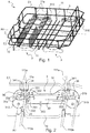
- the figure 1 illustrates a three-dimensional view of a dish basket 1 intended to be mounted in a washing tub of a dishwasher (not shown).
- the crockery basket 1 comprises a structure of longitudinal threads 10 and of transverse threads 11 crossed.
- the dish basket 1 comprises a bottom delimited by two longitudinal sides C1, C2 and two transverse sides. Horizontal portions of the longitudinal threads 10 and of the horizontal portions 110a of the transverse threads 11 form the bottom of the dish basket 1.
- the bottom of the basket is suitable for receiving dishes to be washed.
- the longitudinal threads 10 and the transverse threads 11 are structural threads of the dishwashing basket 1 and in this sense participate in the rigidity of the dishwashing basket and its structural strength.
- the crockery basket 1 comprises profiled comb elements 2 adapted to support and hold the crockery in place.
- comb-shaped element should be understood as designating an element having the shape of a comb, that is to say provided with several teeth, or a row of teeth which are substantially parallel to one another.
- the longitudinal sides C1, C2 are parallel to guide rails (not shown) on which the crockery basket 1 is intended to move.
- the guide rails are conventionally arranged on side walls of the washing tub of the dishwasher.
- At least one wheel support 3 accommodating at least one wheel 310 is fixed to the dish basket 1. Said at least one wheel is intended to move on a guide rail.
- two wheel supports 3 are fixed to each longitudinal side C1, C2 of the dish basket 1.
- the roller supports 3 provided with rollers 310 allow movement in the longitudinal direction of the dish basket 1.
- Each caster support 3 here accommodates two casters 310.
- rollers 310 can vary.
- the caster support 3 comprises a main portion 30 extending in a horizontal plane and extended on either side by a first casing 31a and a second casing 31b.
- Each casing 31a, 31b accommodates a caster 310 allowing the translational movement of the dish basket 1.
- Each caster 310 comprises an axis of rotation A1 or of revolution around which the caster 310 turns.
- the first casing 31a and the second casing 31b play a role of protection against wear and soiling of rollers 310 for example when loading dishes into the dish rack.
- the main portion 30 comprises a first end 301 and a second end 302.
- the caster support 3 also comprises a vertical flank 32 extending perpendicularly to the main portion 30.
- the vertical flank 32 here extends substantially at the same level as' a longitudinal side of the crockery basket, so that the vertical flank 32 does not protrude beyond the width of the crockery basket 1.
- the vertical flank 32 and a longitudinal side C1 or C2 belong substantially to the same vertical plane.
- the first casing 31a and the second casing 31b extend around the axis of revolution A.
- the first casing 31a and the second casing 31b extend perpendicularly to the vertical flank 32 towards the inside of the dish basket 1. This is understood to mean by "inside the dish basket” the bottom of the dish basket 1.
- the wheel support 3 thus configured does not protrude beyond the width of the dish basket, which prevents the wheel support occupying space in width in the washing tub.
- the caster support 3 may not include a casing housing the castors.
- the casters can be directly mounted on the caster support without a casing enveloping said castors.
- the roller supports 3 are attached to transverse threads 11a of the dish basket 1.
- the transverse threads 11a to which the roller supports 3 are attached extend over the entire width of the dish basket 1.
- the transverse threads 11a here have a C-shaped and include a horizontal part 110a extended on either side by two vertical wings 111a.
- transverse son 11a can have a different shape.
- each caster support is fixed to at least one transverse wire 11a, the latter supporting a second caster holder facing the first caster holder.
- the assembly formed is thus symmetrical with respect to a longitudinal median axis A0 of the crockery basket 1.
- the symmetrical arrangement of the roller supports 3 improves the stability and the fluidity of the translational movement of the crockery basket 1.
- each wheel support is attached to two transverse wires supporting a second wheel support facing the first wheel support.
- a wheel support 3 attached to a longitudinal side of the crockery basket 1.
- the description relating to this wheel support 3 is of course valid for all the other wheel supports of the basket. washing up.
- the structure of the caster support 3 according to the embodiment described being symmetrical, the remainder of the description is made for half of the caster support 3 comprising the first casing 31a but obviously remains valid for the other half of the caster.
- caster support 3 comprises the second casing 31b.
- the roller support 3 comprises at least one fixing zone suitable for accommodating at least a portion of a transverse wire 11a.
- the roller support 3 comprises a lower fixing zone 33.
- the lower fixing zone 33 is here formed in the first end 301 of the main portion 30.
- the lower fixing zone 33 here comprises a first housing 330 adapted to accommodate a portion of the horizontal part 111a of the transverse wire 11a.
- the first housing 330 is surmounted by claws 332 intended to hold the horizontal part 111a of the transverse wire 11a in its first housing 330.
- the first housing 330 also communicates with a second housing 331, also called support means and described below.
- the roller support 3 comprises an upper fixing zone 34, formed here in the vertical sidewall 32.
- the upper fixing zone 34 is adapted to accommodate a portion of one of the vertical wings 111a of the wire. transverse 11a.
- the lower fixing zone 33 and the upper fixing zone 34 are here formed in the same plane perpendicular to the longitudinal plane so as to be able to accommodate respectively a portion of the part. horizontal 110a and a portion of a vertical wing 111a of the transverse wire 11a.
- the axis of rotation A1 of the roller 310 housed in the casing 31a does not belong to the plane in which the lower fixing zone 33 and the upper fixing zone 34 are formed. This favors the formation of the casing 31a inwardly. of the dish rack 1.
- the upper fixing zone 34 here comprises hooks 341 adapted to hold the vertical wing 111a in place.
- the lower attachment area 33 and the upper attachment area 34 may be formed elsewhere in the caster holder 3.
- the attachment area 33 may be formed in the middle of the main portion 30 and the The upper attachment area 34 may be formed in the middle of the vertical flank 32.
- the lower attachment area 33 and the upper attachment area 34 may be formed differently. Any other means of attachment can be considered as an alternative.
- two profiled comb elements 2 are fixed to the roller support 3.
- the profiled comb elements 2 can occupy a deployed position illustrated in FIG. figure 3 and a folded-down position shown in figure 4 .
- Each comb-shaped element 2 comprises a horizontal wire 20 extended by a fixing wing 22, and teeth 21 parallel to each other and forming an angle with the horizontal wire 20.
- the teeth 21 are spaced apart so as to be able to accommodate washing up.
- the teeth 21 are here substantially perpendicular to the horizontal wire 20.
- the geometry of the profiled comb element 2 may be different.
- the profiled comb elements 2 When they are in the deployed position, the profiled comb elements 2 are suitable for supporting crockery, for example for holding plates in place. When the comb-shaped element 2 is in the deployed position, the teeth 21 extend vertically so as to be able to hold the dishes placed in the dishes basket in place.
- the teeth 21 extend in a horizontal direction.
- the folded down position is occupied, for example, when the crockery basket is emptied of crockery.
- the second housing 331 of the lower fixing zone 33 is adapted to accommodate a portion of the horizontal wire 20 of the comb-shaped element 2.
- the hook shape at the end of the second housing 331 allows advantageously to keep the horizontal wire 20, while allowing its rotation.
- the first housing 330 and the second housing 331 of the lower fixing zone 33 make it possible to partially block the movement of the roller support 3 fixed on the horizontal part 110a of the transverse wire 11a and on the horizontal wire 20 of the comb profiled element. 2.
- the fixing of the horizontal wire 20 of the comb shaped element 2 can be carried out on a different attachment zone from that of the transverse wire.
- another fixing zone intended to house only the horizontal wire 20 can be formed in the roller support 3.
- the arrangement of the fixing zones and their structure may vary.
- the caster support comprises at least one locking member 36 adapted to keep fixed the fixing wing 22 of the comb profiled element 2.
- the fixing wing 22 is kept locked when the comb profiled element 2 is in position. deployed position.
- two locking members 36 are formed on either side of the lower fixing zone 33.
- the caster support 3 is thus reversible. Indeed, the formation of a locking member 36 on each side of the lower fixing zone 33 makes it possible to fix the roller support 3 indifferently to one or the other of the two longitudinal sides C1, C2 of the dish basket. 1.
- the locking members 36 are clips here, but other variants making it possible to block the movement of the fixing wing 22 can of course be envisaged.
- the number of locking members as well as their arrangement in the caster support may vary.
- At least one housing can be formed in the roller support 3 in order to accommodate a portion of the fixing flange 22 so as to keep it fixed when the profiled comb element 2 is in position. deployed.
- the caster support 3 further comprises a projection 303.
- the projection 303 is here formed substantially in the middle of the main portion 30 of the caster support 3.
- the projection 303 is adapted to hold in place one of the teeth 21 of a comb profiled element 2 when the latter is in the folded position. As shown in figure 4 , a portion of the tooth 21 rests on the projection 303 which allows it to be held in place.
- the other teeth of the comb-shaped element 2 are integral with the same horizontal wire 20 and therefore held in place at the same time.
- projection 303 can be envisaged, for example a hook or a housing cavity.
- the caster support can have other geometric shapes and can be asymmetrical.
- the roller supports can be attached to the dish rack in a completely different arrangement.
Landscapes
- Washing And Drying Of Tableware (AREA)
Description
- La présente invention concerne un panier à vaisselle et plus particulièrement un support de roulette pour panier à vaisselle.
- De manière générale, les lave-vaisselle domestiques comprennent au moins un panier à vaisselle monté en translation dans une cuve de lavage. La cuve de lavage comprend au moins deux rails de guidage ménagés respectivement sur deux parois latérales de la cuve de lavage.
- Classiquement, des roulettes sont fixées au panier à vaisselle et permettent à celui-ci de se déplacer sur les rails de guidage. Les roulettes peuvent être logées dans des support de roulette.
- Dans toute la suite du document, des notions de longitudinal, transversal, horizontal et vertical sont introduites. La direction longitudinale doit être comprise comme étant celle du déplacement du panier à vaisselle ; elle est donc parallèle aux rails de guidage. Les directions transversales doivent être comprises comme étant perpendiculaires à la direction longitudinale. Par ailleurs, le plan horizontal doit être compris comme étant parallèle au plan formé par le fond du panier à vaisselle et un plan vertical comme étant perpendiculaire au plan horizontal.
- Généralement, un panier à vaisselle comprend une structure de fils longitudinaux et de fils transversaux entrecroisés permettant de supporter la vaisselle.
- Il est connu dans l'état de la technique, l'utilisation de fils rapportés afin de fixer une roulette ou le support de roulette logeant la roulette à un côté du panier à vaisselle. Le fil rapporté peut être longitudinal, horizontal ou vertical.
- Le terme « rapporté » doit être compris comme ne faisant pas partie de la structure initiale du panier à vaisselle dans la mesure où le rôle premier du fil rapporté n'est pas la tenue structurelle du panier à vaisselle. En effet, le fil rapporté est spécialement conçu et monté afin de permettre la fixation et le maintien d'une roulette ou d'un support de roulette au panier à vaisselle. Aussi, lors de la réalisation du panier, ce dernier comporte des fils structurels et des fils rapportés qui sont assemblés en même temps, sans pour autant avoir la même finalité.
- Ainsi, les documents
US 2009/0151758 etFR 2 718 006 - L'utilisation de fils rapportés encombre la structure du panier à vaisselle et requiert l'utilisation de fixations supplémentaires destinées à fixer les fils rapportés au panier à vaisselle et au support de roulette. De plus, cela engendre un coût supplémentaire lors de la fabrication du panier à vaisselle dû à l'ajout de matière.
- La présente invention a pour but de résoudre au moins l'un des inconvénients précités.
- Ainsi l'invention porte sur un panier à vaisselle comprenant une structure de fils longitudinaux et de fils transversaux entrecroisés, et un support de roulette fixé sur un des deux côtés longitudinaux du panier à vaisselle. Le support de roulette comporte au moins une roulette adaptée à se déplacer sur un rail de guidage dans une cuve de lave-vaisselle. Le support de roulette comprend au moins une zone de fixation adaptée à loger une portion d'au moins un fil transversal du panier à vaisselle.
- Au moins un fil transversal s'étend sur toute la largeur du panier à vaisselle. Ledit au moins un fil transversal comprend une partie horizontale prolongée de part et d'autre par deux ailes verticales. Le support de roulette comprend une zone de fixation inférieure et une zone de fixation supérieure.
- Selon l'invention, la zone de fixation inférieure et la zone de fixation supérieure sont adaptées à loger respectivement une portion de la partie horizontale et une portion d'une des ailes verticales dudit au moins un fil transversal.
- Le fil transversal s'étendant sur toute la largeur du panier à vaisselle est un fil structurel du panier à vaisselle. Le support de roulette est ainsi fixé sur un fil indispensable au panier à vaisselle, ce qui permet de s'affranchir de l'utilisation de fils rapportés afin de fixer le support de roulette. Le panier à vaisselle ainsi constitué possède une structure optimisée.
- La fixation du support de roulette au panier à vaisselle au niveau de deux zones de fixation permet d'assurer un bon assemblage du support de roulette au panier à vaisselle et ainsi d'assurer un mouvement de translation horizontale du panier à vaisselle fluide et stable.
- Avantageusement, le support de roulette comprend un flanc vertical, la zone de fixation supérieure étant formée dans le flanc vertical.
- Selon une caractéristique, le support de roulette comprend au moins un carter s'étendant perpendiculairement au flanc vertical vers l'intérieur du panier à vaisselle, ledit au moins un carter logeant ladite au moins une roulette.
- Le carter permet de protéger la roulette de l'usure et de la salissure. La formation du carter vers l'intérieur du panier à vaisselle permet un gain d'espace dans la cuve de lavage.
- Selon une autre caractéristique, le panier à vaisselle comprend un élément profilé en peigne adapté à supporter de la vaisselle et pouvant occuper une position déployée et une position rabattue. L'élément profilé en peigne comprend un fil horizontal prolongé par une aile de fixation, et des dents sensiblement parallèles entre elles formant un angle avec le fil horizontal, le support de roulette comportant un moyen de support de l'élément profilé en peigne.
- Lorsque l'élément profilé en peigne est en position déployée, les dents s'étendent verticalement de sorte à pouvoir maintenir en place la vaisselle disposée dans le panier à vaisselle. Lorsque l'élément profilé en peigne est en position rabattue, les dents s'étendent suivant une direction horizontale, ce qui permet un gain d'espace dans le panier à vaisselle pouvant être utile par exemple pour charger de la vaisselle de grande dimension dans le panier à vaisselle.
- Selon une caractéristique, la zone de fixation du support de roulette comprend un premier logement communiquant avec un deuxième logement formant le moyen de support, le premier logement étant adapté à loger une portion dudit au moins un fil transversal et le deuxième logement étant adapté à loger une portion dudit fil horizontal de l'élément profilé en peigne.
- Selon une caractéristique, le support de roulette comprend un organe de blocage permettant de maintenir fixe l'aile de fixation de l'élément profilé en peigne lorsque l'élément profilé en peigne est dans la position déployée.
- En fixant l'élément profilé en peigne au moyen d'un organe de blocage, le mouvement de l'élément profilé en peigne est ainsi bloqué, ce qui permet d'éviter des incidents dus à un mauvais maintien en place de la vaisselle, par exemple chute ou casse de la vaisselle.
- Avantageusement, le support de roulette comprend deux organes de blocage de part et d'autre du moyen de support.
- La formation de deux organes de blocage de part et d'autre de la zone de fixation permet de rendre le support de roulette réversible. En effet, le support de roulette peut être fixé indifféremment à l'un ou l'autre des côtés longitudinaux. Lors du montage du support de roulette au panier à vaisselle, cela permet de ne pas se soucier du sens de montage.
- Selon une caractéristique, le support de roulette comprend une saillie adaptée à maintenir en place l'une des dents de l'élément profilé en peigne lorsque ledit élément profilé en peigne est en position rabattue.
- Selon une autre caractéristique, le panier à vaisselle comprend deux éléments profilés en peigne, ledit support de roulette comprenant deux zones de fixation inférieures, les deux zones de fixation inférieures étant adaptées à loger respectivement deux portions de fils horizontaux des deux éléments profilés en peigne.
- Avantageusement, le support de roulette comporte deux roulettes.
- Cela participe à fluidifier le mouvement de translation horizontale du panier à vaisselle.
- Selon une caractéristique, le panier à vaisselle comprend deux supports de roulette fixés respectivement sur les deux côtés longitudinaux du panier à vaisselle, la zone de fixation de chaque support de roulette étant adaptée à loger une portion dudit au moins un fil transversal.
- La disposition des supports de roulette de part et d'autre du panier à vaisselle participe à la stabilité et à la fluidité du mouvement de translation horizontale du panier à vaisselle.
- La fixation de deux supports de roulette sur un même fil transversal participe également à la stabilité et à la fluidité du mouvement de translation horizontale du panier à vaisselle.
- Selon une autre caractéristique, le panier à vaisselle comprend deux supports de roulette fixés sur chacun des côtés longitudinaux du panier à vaisselle.
- D'autres particularités et avantages de l'invention apparaîtront encore dans la description ci-après.
- Aux dessins annexés, donnés à titre d'exemples non limitatifs :
- la
figure 1 est une vue tridimensionnelle d'un panier à vaisselle comprenant des supports de roulette selon un mode de réalisation conforme à l'invention ; - la
figure 2 est une vue de détail de l'un des supports de roulette de lafigure 1 fixé à deux fils transversaux du panier à vaisselle ; - la
figure 3 est une vue de détail de l'un des supports de roulette de lafigure 1 fixé à deux fils transversaux et à deux éléments profilés en peigne en position déployée ; et - la
figure 4 est une vue de détail analogue à celle de lafigure 3 et dans laquelle les deux éléments profilés en peigne sont en position rabattue. - La
figure 1 illustre une vue tridimensionnelle d'un panier à vaisselle 1 destiné à être monté dans une cuve de lavage d'un lave-vaisselle (non représentés). Le panier à vaisselle 1 comprend une structure de fils longitudinaux 10 et de fils transversaux 11 entrecroisés. Le panier à vaisselle 1 comprend un fond délimité par deux côtés longitudinaux C1, C2 et deux côtés transversaux. Des parties horizontales des fils longitudinaux 10 et des parties horizontales 110a des fils transversaux 11 forment le fond du panier à vaisselle 1. Le fond du panier est adapté à recevoir de la vaisselle à laver. - Les fils longitudinaux 10 et les fils transversaux 11 sont des fils structurels du panier à vaisselle 1 et participent à ce sens à la rigidité du panier à vaisselle et à sa tenue structurelle.
- Dans ce mode de réalisation, le panier à vaisselle 1 comprend des éléments profilés en peigne 2 adaptés à supporter et à maintenir en place la vaisselle. L'expression « élément profilé en peigne » doit être comprise comme désignant un élément ayant la forme d'un peigne c'est-à-dire muni de plusieurs dents, ou rangée de dents sensiblement parallèles les unes par rapport aux autres.
- Les côtés longitudinaux C1, C2 sont parallèles à des rails de guidage (non représentés) sur lesquels le panier à vaisselle 1 est destiné à se déplacer. Les rails de guidage sont classiquement disposés sur des parois latérales de la cuve de lavage du lave-vaisselle.
- Afin de permettre le mouvement de translation horizontale du panier à vaisselle, au moins un support de roulette 3 logeant au moins une roulette 310 est fixé au panier à vaisselle 1. Ladite au moins une roulette est destinée à se déplacer sur un rail de guidage.
- Selon l'exemple de réalisation décrit, deux supports de roulettes 3 sont fixés à chaque côté longitudinal C1, C2 du panier à vaisselle 1. Les supports de roulettes 3 munis de roulettes 310 permettent le déplacement suivant la direction longitudinale du panier à vaisselle 1. Chaque support de roulette 3 loge ici deux roulettes 310.
- Bien entendu, le nombre de supports de roulettes 3, de roulettes 310 ainsi que leurs dispositions peuvent varier.
- Selon le mode de réalisation illustré, le support de roulette 3 comprend une portion principale 30 s'étendant dans un plan horizontal et prolongée de part et d'autre par un premier carter 31a et un deuxième carter 31b. Chaque carter 31a, 31b loge une roulette 310 permettant le mouvement de translation du panier à vaisselle 1. Chaque roulette 310 comprend un axe de rotation A1 ou de révolution autour duquel tourne la roulette 310. Le premier carter 31a et le deuxième carter 31 b jouent un rôle de protection contre l'usure et la salissure des roulettes 310 par exemple lors du chargement de la vaisselle dans le panier à vaisselle.
- La portion principale 30 comprend une première extrémité 301 et une deuxième extrémité 302. Le support de roulette 3 comprend également un flanc vertical 32 s'étendant perpendiculairement à la portion principale 30. Le flanc vertical 32 s'étend ici sensiblement au même niveau qu'un côté longitudinal du panier à vaisselle, de sorte que le flanc vertical 32 ne dépasse pas au-delà de la largeur du panier à vaisselle 1. En d'autre termes, le flanc vertical 32 et un côté longitudinal C1 ou C2 appartiennent sensiblement au même plan vertical.
- Le premier carter 31a et le deuxième carter 31b s'étendent autour de l'axe de révolution A. Le premier carter 31a et le deuxième carter 31b s'étendent perpendiculairement au flanc vertical 32 vers l'intérieur du panier à vaisselle 1. On entend par « intérieur du panier à vaisselle » le fond du panier à vaisselle 1. Cela permet de disposer dans la cuve de lavage un panier à vaisselle ayant sensiblement la même largeur que la cuve de lavage et donc d'optimiser la quantité de vaisselle pouvant être reçue dans le panier à vaisselle. En effet, le support de roulette 3 ainsi configuré ne dépasse pas au-delà de la largeur du panier à vaisselle ce qui évite que le support de roulette occupe de l'espace en largeur dans la cuve de lavage.
- Bien entendu, le support de roulette 3 peut ne pas comprendre de carter logeant les roulettes. Les roulettes peuvent être directement montées sur le support de roulette sans carter enveloppant lesdites roulettes.
- Les supports de roulette 3 sont fixés à des fils transversaux 11a du panier à vaisselle 1. Les fils transversaux 11a auxquels sont fixés les supports de roulette 3 s'étendent sur toute la largeur du panier à vaisselle 1. Les fils transversaux 11a présentent ici une forme en C et comprennent une partie horizontale 110a prolongée de part et d'autre par deux ailes verticales 111a.
- Bien entendu, les fils transversaux 11a peuvent présenter une forme différente.
- Les quatre supports de roulettes 3 sont ici disposés en vis-à-vis et sont fixés deux à deux aux mêmes fils transversaux 11a. En d'autres termes, chaque support de roulette est fixé à au moins un fil transversal 11a, ce dernier supportant un deuxième support de roulette se trouvant face au premier support de roulette. L'ensemble formé est ainsi symétrique par rapport à un axe médian longitudinal A0 du panier à vaisselle 1. La disposition symétrique des supports de roulette 3 améliore la stabilité et la fluidité du mouvement de translation du panier à vaisselle 1. Dans l'exemple de réalisation illustré, chaque support de roulette est fixé à deux fils transversaux supportant un deuxième support de roulette se trouvant face au premier support de roulette.
- Dans la suite du document, il est fait référence à un support de roulette 3 accroché à un côté longitudinal du panier à vaisselle 1. La description portant sur ce support de roulette 3 est bien entendu valable pour tous les autres supports de roulette du panier à vaisselle. De plus, la structure du support de roulette 3 selon le mode de réalisation décrit étant symétrique, la suite de la description est réalisée pour la moitié du support de roulette 3 comprenant le premier carter 31a mais reste bien évidemment valable pour l'autre moitié du support de roulette 3 comprend le deuxième carter 31b.
- Le support de roulette 3 comprend au moins une zone de fixation adaptée à loger au moins une portion d'un fil transversal 11a. Selon l'exemple de réalisation décrit, le support de roulette 3 comprend une zone de fixation inférieure 33. La zone de fixation inférieure 33 est ici formée dans la première extrémité 301 de la portion principale 30. La zone de fixation inférieure 33 comprend ici un premier logement 330 adapté à loger une portion de la partie horizontale 111a du fil transversal 11a. Le premier logement 330 est surmonté des griffes 332 destinées à maintenir la partie horizontale 111a du fil transversal 11a dans son premier logement 330.
- Le premier logement 330 communique par ailleurs avec un second logement 331, également appelé moyen de support et décrit par la suite.
- Selon le mode de réalisation décrit, le support de roulette 3 comprend une zone de fixation supérieure 34, formée ici dans le flanc vertical 32. La zone de fixation supérieure 34 est adaptée à loger une portion de l'une des ailes verticales 111a du fil transversal 11a. La zone de fixation inférieure 33 et la zone de fixation supérieure 34 sont ici formées dans un même plan perpendiculaire au plan longitudinal de sorte à pouvoir loger respectivement une portion de la partie horizontale 110a et une portion d'une aile verticale 111a du fil transversal 11a. L'axe de rotation A1 de la roulette 310 logée dans le carter 31a n'appartient pas au plan dans lequel sont formées la zone de fixation inférieure 33 et la zone de fixation supérieure 34. Cela favorise la formation du carter 31a vers l'intérieur du panier à vaisselle 1.
- La zone de fixation supérieure 34 comprend ici des crochets 341 adaptés à maintenir en place l'aile verticale 111a.
- La fixation du fil transversal 11a sur deux zones de fixation inférieure 33 et supérieure 34 favorise une bonne fixation du support de roulette au fil transversal et par conséquent au panier à vaisselle.
- Bien entendu, la zone de fixation inférieure 33 et la zone de fixation supérieure 34 peuvent être formées ailleurs dans le support de roulette 3. A titre d'exemple, la zone de fixation 33 peut être formée au milieu de la portion principale 30 et la zone de fixation supérieure 34 peut être formée au milieu du flanc vertical 32. De plus, la zone de fixation inférieure 33 et la zone de fixation supérieure 34 peuvent être formées différemment. Tout autre moyen de fixation peut être envisagé en alternative.
- Selon l'exemple de réalisation illustré, deux éléments profilés en peigne 2 sont fixés au support de roulette 3. Les éléments profilés en peigne 2 peuvent occuper une position déployée illustrée à la
figure 3 et une position rabattue illustrée à lafigure 4 . - Chaque élément profilé en peigne 2 comprend un fil horizontal 20 prolongé par une aile de fixation 22, et des dents 21 parallèles entre elles et formant un angle avec le fil horizontal 20. Les dents 21 sont espacées entre elles de sorte à pouvoir accueillir de la vaisselle. Les dents 21 sont ici sensiblement perpendiculaires au fil horizontal 20. Bien entendu, la géométrie de l'élément profilé en peigne 2 peut être différente.
- Lorsqu'ils sont en position déployée, les éléments profilés en peigne 2 sont adaptés à supporter de la vaisselle, par exemple à maintenir en place des assiettes. Lorsque l'élément profilé en peigne 2 est en position déployée, les dents 21 s'étendent verticalement de sorte à pouvoir maintenir en place la vaisselle disposée dans le panier à vaisselle.
- Lorsque l'élément profilé en peigne 2 est en position rabattue, les dents 21 s'étendent suivant une direction horizontale. La position rabattue est occupée par exemple lorsque le panier à vaisselle est vidé de la vaisselle.
- Bien entendu, seul un peigne, ou plusieurs peignes peuvent être rabattus. Cela permettrait ainsi de gagner de l'espace dans le panier à vaisselle, par exemple afin de pouvoir placer de la vaisselle de grande dimension.
- Selon le mode de réalisation décrit, le deuxième logement 331 de la zone de fixation inférieure 33 est adaptée à loger une portion du fil horizontal 20 de l'élément profilé en peigne 2. La forme en crochets à l'extrémité du second logement 331 permet avantageusement de maintenir le fil horizontal 20, tout en autorisant sa rotation.
- La premier logement 330 et le deuxième logement 331 de la zone de fixation inférieure 33 permettent de bloquer en partie le mouvement du support de roulette 3 fixé sur partie horizontale 110a du fil transversal 11a et sur le fil horizontal 20 de l'élément profilé en peigne 2.
- Bien entendu, la fixation du fil horizontal 20 de l'élément profilé en peigne 2 peut être réalisée sur une zone de fixation différente de celle du fil transversal. Dans une alternative, une autre zone de fixation destinée à loger uniquement le fil horizontal 20 peut être formée dans le support de roulette 3.
- Par ailleurs, selon la forme de l'élément en peigne et du fil transversal, la disposition des zones de fixation et leur structure peuvent varier.
- Le support de roulette comprend au moins un organe de blocage 36 adapté à maintenir fixe l'aile de fixation 22 de l'élément profilé en peigne 2. L'aile de fixation 22 est maintenue bloquée lorsque l'élément profilé en peigne 2 est en position déployée.
- Selon le mode de réalisation décrit, deux organes de blocage 36 sont formés de part et d'autre de la zone de fixation inférieure 33. Le support de roulette 3 est ainsi réversible. En effet, la formation d'un organe de blocage 36 de chaque côté de la zone de fixation inférieure 33 permet de fixer le support de roulette 3 indifféremment à l'un ou l'autre des deux côtés longitudinaux C1, C2 du panier à vaisselle 1.
- Les organes de blocage 36 sont ici des clips mais d'autres variantes permettant de bloquer le mouvement de l'aile de fixation 22 peuvent bien entendu être envisagées. De plus, le nombre d'organes de blocage ainsi que leur disposition dans le support de roulette peuvent varier.
- A titre d'exemple non limitatif, au moins un logement peut être formé dans le support de roulette 3 afin de loger une portion de l'aile de fixation 22 de sorte à la maintenir fixe lorsque l'élément profilé en peigne 2 est en position déployée.
- Le support de roulette 3 comprend en outre une saillie 303. La saillie 303 est ici formée sensiblement au milieu de la portion principale 30 du support de roulette 3. La saillie 303 est adaptée à maintenir en place l'une des dents 21 d'un élément profilé en peigne 2 lorsque ce dernier est en position rabattue. Comme illustré à la
figure 4 , une portion de la dent 21 repose sur la saillie 303 ce qui permet de la maintenir en place. Les autres dents de l'élément profilé en peigne 2 sont solidaires du même fil horizontal 20 et donc maintenues en place par la même occasion. - Bien entendu, d'autres variantes à la saillie 303 peuvent être envisagées, par exemple un crochet ou une cavité de logement.
- Bien entendu, la présente invention n'est pas limitée au mode de réalisation décrit ci-avant.
- La description du présent document est faite pour des supports de roulette ayant une construction symétrique et qui sont fixés de façon symétrique au panier à vaisselle. Ceci présente des avantages quant à la stabilité de la structure du panier à vaisselle et celle de son mouvement de translation horizontale.
- Bien entendu, le support de roulette peut présenter d'autres formes géométriques et peut être asymétrique. De plus, les supports de roulettes peuvent être fixés au panier à vaisselle suivant une toute autre disposition.
Claims (12)
- Panier à vaisselle (1) comprenant une structure de fils longitudinaux (10) et de fils transversaux (11) entrecroisés, et un support de roulette (3) fixé sur un des deux côtés longitudinaux (C1 ; C2) du panier à vaisselle, ledit support de roulette (3) comportant au moins une roulette (310) adaptée à se déplacer sur un rail de guidage dans une cuve de lave-vaisselle, au moins un fil transversal (11a) s'étendant sur toute la largeur du panier à vaisselle (1) et comprenant une partie horizontale (110a) prolongée de part et d'autre par deux ailes verticales (111a), ledit support de roulette (3) comprenant une zone de fixation inférieure (33) et une zone de fixation supérieure (34), ledit panier à vaisselle (1) étant caractérisé en ce que la zone de fixation inférieure (33) et la zone de fixation supérieure (34) sont adaptées à loger respectivement une portion de la partie horizontale (110a) et une portion d'une desdites ailes verticales (111a) dudit au moins un fil transversal (11a).
- Panier à vaisselle (1) conforme à la revendication 1, caractérisé en ce que ledit support de roulette (3) comprend un flanc vertical (32), ladite zone de fixation supérieure (34) étant formée dans ledit flanc vertical (32).
- Panier à vaisselle (1) conforme à la revendication 2, caractérisé en ce que ledit support de roulette (3) comprend au moins un carter (31a ; 31b) s'étendant perpendiculairement audit flanc vertical (32) vers l'intérieur du panier à vaisselle (1), ledit au moins un carter (31a ; 31b) logeant ladite au moins une roulette (310).
- Panier à vaisselle (1) conforme à l'une des revendications précédentes, caractérisé en ce qu'il comprend un élément profilé en peigne (2) adapté à supporter de la vaisselle et pouvant occuper une position déployée et une position rabattue, ledit élément profilé en peigne (2) comprenant un fil horizontal (20) prolongé par une aile de fixation (22), et des dents (21) sensiblement parallèles entre elles et formant un angle avec ledit fil horizontal (20), ledit support de roulette (3) comportant un moyen de support (331) dudit élément profilé en peigne (2).
- Panier à vaisselle (1) conforme à la revendication 4, caractérisé en ce que ladite zone de fixation du support de roulette (3) comprend un premier logement (330) communiquant avec un deuxième logement formant ledit moyen de support (331), ledit premier logement (330) étant adapté à loger une portion dudit au moins un fil transversal (11a) et ledit deuxième logement (331) étant adapté à loger une portion dudit fil horizontal (20) dudit élément profilé en peigne (2).
- Panier à vaisselle (1) conforme à la revendication 4 ou 5, caractérisé en ce que le support de roulette (3) comprend un organe de blocage (36) permettant de maintenir fixe l'aile de fixation (22) dudit élément profilé en peigne (2) lorsque l'élément profilé en peigne (2) est dans la position déployée.
- Panier à vaisselle (1) conforme à la revendication 6, caractérisé en ce que le support de roulette (3) comprend deux organes de blocage (36) de part et d'autre dudit moyen de support (331).
- Panier à vaisselle (1) conforme à l'une des revendications 4 à 7, caractérisé en ce que ledit support de roulette (3) comprend une saillie (303) adaptée à maintenir en place l'une desdites dents (21) de l'élément profilé en peigne (2) lorsque ledit élément profilé en peigne (2) est en position rabattue.
- Panier à vaisselle (1) conforme à l'une des revendications 4 à 8, caractérisé en ce qu'il comprend deux éléments profilés en peigne (2), ledit support de roulette (3) comprenant deux zones de fixation inférieures (33), lesdites deux zones de fixation inférieures (33) étant adaptées à loger respectivement deux portions de fils horizontaux (20) desdits deux éléments profilés en peigne (2).
- Panier à vaisselle (1) conforme à l'une des revendications précédentes, caractérisé en ce que ledit support de roulette (3) comporte deux roulettes (310).
- Panier à vaisselle (1) conforme à l'une des revendications précédentes, caractérisé en ce qu'il comprend deux supports de roulette (3) fixés respectivement sur les deux côtés longitudinaux (C1 ; C2) du panier à vaisselle (1), ladite au moins une zone de fixation (33 ; 34) de chaque support de roulette étant adaptée à loger une portion dudit au moins un fil transversal (11a).
- Panier à vaisselle (1) conforme à l'une des revendications précédentes, caractérisé en ce qu'il comprend deux supports de roulette (3) fixés sur chacun desdits deux côtés longitudinaux (33 ;34) du panier à vaisselle.
Applications Claiming Priority (1)
| Application Number | Priority Date | Filing Date | Title |
|---|---|---|---|
| FR1852229A FR3078876B1 (fr) | 2018-03-15 | 2018-03-15 | Panier a vaisselle comprenant un support de roulette |
Publications (2)
| Publication Number | Publication Date |
|---|---|
| EP3539442A1 EP3539442A1 (fr) | 2019-09-18 |
| EP3539442B1 true EP3539442B1 (fr) | 2021-02-17 |
Family
ID=62222977
Family Applications (1)
| Application Number | Title | Priority Date | Filing Date |
|---|---|---|---|
| EP19161989.9A Active EP3539442B1 (fr) | 2018-03-15 | 2019-03-11 | Panier à vaisselle comprenant un support de roulette |
Country Status (3)
| Country | Link |
|---|---|
| EP (1) | EP3539442B1 (fr) |
| ES (1) | ES2864690T3 (fr) |
| FR (1) | FR3078876B1 (fr) |
Families Citing this family (2)
| Publication number | Priority date | Publication date | Assignee | Title |
|---|---|---|---|---|
| CN115721243B (zh) * | 2021-09-01 | 2026-01-30 | 芜湖美的智能厨电制造有限公司 | 餐具收纳结构、承载篮和家用电器 |
| KR20230063760A (ko) * | 2021-11-02 | 2023-05-09 | 엘지전자 주식회사 | 식기세척기 |
Family Cites Families (4)
| Publication number | Priority date | Publication date | Assignee | Title |
|---|---|---|---|---|
| JPS5730995Y2 (fr) * | 1977-05-26 | 1982-07-07 | ||
| IT235015Y1 (it) | 1994-04-01 | 2000-03-31 | Zanussi Elettrodomestici | Cesto per lavastoviglie con setto mobile |
| US20090151758A1 (en) * | 2007-12-12 | 2009-06-18 | Electrolux Home Products, Inc. | Lower rack for a dishwasher and associated apparatuses |
| US9526399B2 (en) * | 2012-05-14 | 2016-12-27 | Haier Us Appliance Solutions, Inc. | Roller assembly for an appliance |
-
2018
- 2018-03-15 FR FR1852229A patent/FR3078876B1/fr not_active Expired - Fee Related
-
2019
- 2019-03-11 ES ES19161989T patent/ES2864690T3/es active Active
- 2019-03-11 EP EP19161989.9A patent/EP3539442B1/fr active Active
Non-Patent Citations (1)
| Title |
|---|
| None * |
Also Published As
| Publication number | Publication date |
|---|---|
| EP3539442A1 (fr) | 2019-09-18 |
| FR3078876B1 (fr) | 2020-05-29 |
| ES2864690T3 (es) | 2021-10-14 |
| FR3078876A1 (fr) | 2019-09-20 |
Similar Documents
| Publication | Publication Date | Title |
|---|---|---|
| FR2718006A1 (fr) | Panier pour lave-vaisselle à cloison mobile. | |
| EP3539442A1 (fr) | Panier à vaisselle comprenant un support de roulette | |
| FR3072629A1 (fr) | Adaptateur pour un essuie-glace de vehicule automobile et ensemble comportant un tel adaptateur | |
| FR3072628A1 (fr) | Adaptateur pour un essuie-glace de vehicule automobile et essuie-glace comportant un tel adaptateur | |
| WO2007068813A1 (fr) | Chemin de cables en fils, notamment chemin de cables a usage domestique | |
| FR2915364A1 (fr) | Panier a vaisselle comprenant au moins une zone de support d'assiettes | |
| FR3054518B1 (fr) | Dispositif permettant de stationner des velos, et ensemble d'elements permettant de constituer ce dispositif | |
| EP1985223B1 (fr) | Support à vaisselle pour lave-vaisselle | |
| EP2371260B1 (fr) | Dispositif d'aide au maintien d'un panier dans une cuve de lave-vaisselle | |
| FR2775180A1 (fr) | Perfectionnement aux paniers de lave-vaisselle a clayettes | |
| FR2821735A1 (fr) | Lave-vaisselle et panier a couverts pour un tel lave-vaisselle | |
| FR2915362A1 (fr) | Structure de support d'assiettes dans un panier a vaisselle pour lave-vaisselle | |
| EP2766278B1 (fr) | Dispositif d'emballage et emballage pour balai d'essuie-glace a lame courbe et structure flexible integree | |
| FR2958145A1 (fr) | Dispositif telescopique de soutien et de guidage en translation d'un panier de lave-vaisselle | |
| FR3012395A1 (fr) | Corps longitudinal pour un balai d'essuyage d'une vitre de vehicule | |
| FR2983452A1 (fr) | Conteneur de pieces de vehicule automobile | |
| EP1985224B1 (fr) | Structure de support de vaisselle d'un panier à vaisselle pour lave-vaisselle | |
| FR2676421A1 (fr) | Petit panier porte-couverts pour machine a laver la vaisselle. | |
| FR2789290A1 (fr) | Lave-vaisselle muni d'un dispositif de lestage | |
| FR3084028A1 (fr) | Siege pour vehicule automobile destine a l’autopartage dote d’une assise amovible. | |
| WO2024126419A1 (fr) | Adaptateur pour balai d'essuie-glace et dispositif d'essuyage | |
| FR2795940A1 (fr) | Panier pour lave-vaisselle | |
| CH665809A5 (fr) | Etagere amovible d'un chariot de manutention. | |
| WO1998024357A1 (fr) | Panier de lave-vaisselle | |
| FR3142972A1 (fr) | Agencement d’un dispositif de rangement modulaire de coffre de véhicule automobile |
Legal Events
| Date | Code | Title | Description |
|---|---|---|---|
| PUAI | Public reference made under article 153(3) epc to a published international application that has entered the european phase |
Free format text: ORIGINAL CODE: 0009012 |
|
| STAA | Information on the status of an ep patent application or granted ep patent |
Free format text: STATUS: THE APPLICATION HAS BEEN PUBLISHED |
|
| AK | Designated contracting states |
Kind code of ref document: A1 Designated state(s): AL AT BE BG CH CY CZ DE DK EE ES FI FR GB GR HR HU IE IS IT LI LT LU LV MC MK MT NL NO PL PT RO RS SE SI SK SM TR |
|
| AX | Request for extension of the european patent |
Extension state: BA ME |
|
| STAA | Information on the status of an ep patent application or granted ep patent |
Free format text: STATUS: REQUEST FOR EXAMINATION WAS MADE |
|
| 17P | Request for examination filed |
Effective date: 20200303 |
|
| RBV | Designated contracting states (corrected) |
Designated state(s): AL AT BE BG CH CY CZ DE DK EE ES FI FR GB GR HR HU IE IS IT LI LT LU LV MC MK MT NL NO PL PT RO RS SE SI SK SM TR |
|
| GRAP | Despatch of communication of intention to grant a patent |
Free format text: ORIGINAL CODE: EPIDOSNIGR1 |
|
| RIC1 | Information provided on ipc code assigned before grant |
Ipc: A47L 15/50 20060101AFI20200331BHEP |
|
| STAA | Information on the status of an ep patent application or granted ep patent |
Free format text: STATUS: GRANT OF PATENT IS INTENDED |
|
| INTG | Intention to grant announced |
Effective date: 20200507 |
|
| GRAS | Grant fee paid |
Free format text: ORIGINAL CODE: EPIDOSNIGR3 |
|
| GRAJ | Information related to disapproval of communication of intention to grant by the applicant or resumption of examination proceedings by the epo deleted |
Free format text: ORIGINAL CODE: EPIDOSDIGR1 |
|
| GRAL | Information related to payment of fee for publishing/printing deleted |
Free format text: ORIGINAL CODE: EPIDOSDIGR3 |
|
| STAA | Information on the status of an ep patent application or granted ep patent |
Free format text: STATUS: REQUEST FOR EXAMINATION WAS MADE |
|
| INTC | Intention to grant announced (deleted) | ||
| GRAP | Despatch of communication of intention to grant a patent |
Free format text: ORIGINAL CODE: EPIDOSNIGR1 |
|
| STAA | Information on the status of an ep patent application or granted ep patent |
Free format text: STATUS: GRANT OF PATENT IS INTENDED |
|
| INTG | Intention to grant announced |
Effective date: 20201120 |
|
| GRAA | (expected) grant |
Free format text: ORIGINAL CODE: 0009210 |
|
| STAA | Information on the status of an ep patent application or granted ep patent |
Free format text: STATUS: THE PATENT HAS BEEN GRANTED |
|
| AK | Designated contracting states |
Kind code of ref document: B1 Designated state(s): AL AT BE BG CH CY CZ DE DK EE ES FI FR GB GR HR HU IE IS IT LI LT LU LV MC MK MT NL NO PL PT RO RS SE SI SK SM TR |
|
| REG | Reference to a national code |
Ref country code: GB Ref legal event code: FG4D Free format text: NOT ENGLISH |
|
| REG | Reference to a national code |
Ref country code: CH Ref legal event code: EP |
|
| REG | Reference to a national code |
Ref country code: DE Ref legal event code: R096 Ref document number: 602019002449 Country of ref document: DE |
|
| REG | Reference to a national code |
Ref country code: AT Ref legal event code: REF Ref document number: 1360346 Country of ref document: AT Kind code of ref document: T Effective date: 20210315 |
|
| REG | Reference to a national code |
Ref country code: IE Ref legal event code: FG4D Free format text: LANGUAGE OF EP DOCUMENT: FRENCH |
|
| REG | Reference to a national code |
Ref country code: LT Ref legal event code: MG9D |
|
| REG | Reference to a national code |
Ref country code: NL Ref legal event code: MP Effective date: 20210217 |
|
| PG25 | Lapsed in a contracting state [announced via postgrant information from national office to epo] |
Ref country code: GR Free format text: LAPSE BECAUSE OF FAILURE TO SUBMIT A TRANSLATION OF THE DESCRIPTION OR TO PAY THE FEE WITHIN THE PRESCRIBED TIME-LIMIT Effective date: 20210518 Ref country code: FI Free format text: LAPSE BECAUSE OF FAILURE TO SUBMIT A TRANSLATION OF THE DESCRIPTION OR TO PAY THE FEE WITHIN THE PRESCRIBED TIME-LIMIT Effective date: 20210217 Ref country code: HR Free format text: LAPSE BECAUSE OF FAILURE TO SUBMIT A TRANSLATION OF THE DESCRIPTION OR TO PAY THE FEE WITHIN THE PRESCRIBED TIME-LIMIT Effective date: 20210217 Ref country code: BG Free format text: LAPSE BECAUSE OF FAILURE TO SUBMIT A TRANSLATION OF THE DESCRIPTION OR TO PAY THE FEE WITHIN THE PRESCRIBED TIME-LIMIT Effective date: 20210517 Ref country code: LT Free format text: LAPSE BECAUSE OF FAILURE TO SUBMIT A TRANSLATION OF THE DESCRIPTION OR TO PAY THE FEE WITHIN THE PRESCRIBED TIME-LIMIT Effective date: 20210217 Ref country code: PT Free format text: LAPSE BECAUSE OF FAILURE TO SUBMIT A TRANSLATION OF THE DESCRIPTION OR TO PAY THE FEE WITHIN THE PRESCRIBED TIME-LIMIT Effective date: 20210617 Ref country code: NO Free format text: LAPSE BECAUSE OF FAILURE TO SUBMIT A TRANSLATION OF THE DESCRIPTION OR TO PAY THE FEE WITHIN THE PRESCRIBED TIME-LIMIT Effective date: 20210517 |
|
| REG | Reference to a national code |
Ref country code: AT Ref legal event code: MK05 Ref document number: 1360346 Country of ref document: AT Kind code of ref document: T Effective date: 20210217 |
|
| PG25 | Lapsed in a contracting state [announced via postgrant information from national office to epo] |
Ref country code: RS Free format text: LAPSE BECAUSE OF FAILURE TO SUBMIT A TRANSLATION OF THE DESCRIPTION OR TO PAY THE FEE WITHIN THE PRESCRIBED TIME-LIMIT Effective date: 20210217 Ref country code: NL Free format text: LAPSE BECAUSE OF FAILURE TO SUBMIT A TRANSLATION OF THE DESCRIPTION OR TO PAY THE FEE WITHIN THE PRESCRIBED TIME-LIMIT Effective date: 20210217 Ref country code: LV Free format text: LAPSE BECAUSE OF FAILURE TO SUBMIT A TRANSLATION OF THE DESCRIPTION OR TO PAY THE FEE WITHIN THE PRESCRIBED TIME-LIMIT Effective date: 20210217 Ref country code: PL Free format text: LAPSE BECAUSE OF FAILURE TO SUBMIT A TRANSLATION OF THE DESCRIPTION OR TO PAY THE FEE WITHIN THE PRESCRIBED TIME-LIMIT Effective date: 20210217 Ref country code: SE Free format text: LAPSE BECAUSE OF FAILURE TO SUBMIT A TRANSLATION OF THE DESCRIPTION OR TO PAY THE FEE WITHIN THE PRESCRIBED TIME-LIMIT Effective date: 20210217 |
|
| PG25 | Lapsed in a contracting state [announced via postgrant information from national office to epo] |
Ref country code: IS Free format text: LAPSE BECAUSE OF FAILURE TO SUBMIT A TRANSLATION OF THE DESCRIPTION OR TO PAY THE FEE WITHIN THE PRESCRIBED TIME-LIMIT Effective date: 20210617 |
|
| REG | Reference to a national code |
Ref country code: ES Ref legal event code: FG2A Ref document number: 2864690 Country of ref document: ES Kind code of ref document: T3 Effective date: 20211014 |
|
| PG25 | Lapsed in a contracting state [announced via postgrant information from national office to epo] |
Ref country code: CZ Free format text: LAPSE BECAUSE OF FAILURE TO SUBMIT A TRANSLATION OF THE DESCRIPTION OR TO PAY THE FEE WITHIN THE PRESCRIBED TIME-LIMIT Effective date: 20210217 Ref country code: EE Free format text: LAPSE BECAUSE OF FAILURE TO SUBMIT A TRANSLATION OF THE DESCRIPTION OR TO PAY THE FEE WITHIN THE PRESCRIBED TIME-LIMIT Effective date: 20210217 Ref country code: SM Free format text: LAPSE BECAUSE OF FAILURE TO SUBMIT A TRANSLATION OF THE DESCRIPTION OR TO PAY THE FEE WITHIN THE PRESCRIBED TIME-LIMIT Effective date: 20210217 Ref country code: AT Free format text: LAPSE BECAUSE OF FAILURE TO SUBMIT A TRANSLATION OF THE DESCRIPTION OR TO PAY THE FEE WITHIN THE PRESCRIBED TIME-LIMIT Effective date: 20210217 |
|
| REG | Reference to a national code |
Ref country code: DE Ref legal event code: R097 Ref document number: 602019002449 Country of ref document: DE |
|
| PG25 | Lapsed in a contracting state [announced via postgrant information from national office to epo] |
Ref country code: MC Free format text: LAPSE BECAUSE OF FAILURE TO SUBMIT A TRANSLATION OF THE DESCRIPTION OR TO PAY THE FEE WITHIN THE PRESCRIBED TIME-LIMIT Effective date: 20210217 Ref country code: DK Free format text: LAPSE BECAUSE OF FAILURE TO SUBMIT A TRANSLATION OF THE DESCRIPTION OR TO PAY THE FEE WITHIN THE PRESCRIBED TIME-LIMIT Effective date: 20210217 Ref country code: RO Free format text: LAPSE BECAUSE OF FAILURE TO SUBMIT A TRANSLATION OF THE DESCRIPTION OR TO PAY THE FEE WITHIN THE PRESCRIBED TIME-LIMIT Effective date: 20210217 Ref country code: SK Free format text: LAPSE BECAUSE OF FAILURE TO SUBMIT A TRANSLATION OF THE DESCRIPTION OR TO PAY THE FEE WITHIN THE PRESCRIBED TIME-LIMIT Effective date: 20210217 |
|
| REG | Reference to a national code |
Ref country code: BE Ref legal event code: MM Effective date: 20210331 |
|
| PLBE | No opposition filed within time limit |
Free format text: ORIGINAL CODE: 0009261 |
|
| STAA | Information on the status of an ep patent application or granted ep patent |
Free format text: STATUS: NO OPPOSITION FILED WITHIN TIME LIMIT |
|
| 26N | No opposition filed |
Effective date: 20211118 |
|
| PG25 | Lapsed in a contracting state [announced via postgrant information from national office to epo] |
Ref country code: LU Free format text: LAPSE BECAUSE OF NON-PAYMENT OF DUE FEES Effective date: 20210311 Ref country code: IE Free format text: LAPSE BECAUSE OF NON-PAYMENT OF DUE FEES Effective date: 20210311 Ref country code: AL Free format text: LAPSE BECAUSE OF FAILURE TO SUBMIT A TRANSLATION OF THE DESCRIPTION OR TO PAY THE FEE WITHIN THE PRESCRIBED TIME-LIMIT Effective date: 20210217 |
|
| PG25 | Lapsed in a contracting state [announced via postgrant information from national office to epo] |
Ref country code: SI Free format text: LAPSE BECAUSE OF FAILURE TO SUBMIT A TRANSLATION OF THE DESCRIPTION OR TO PAY THE FEE WITHIN THE PRESCRIBED TIME-LIMIT Effective date: 20210217 |
|
| PG25 | Lapsed in a contracting state [announced via postgrant information from national office to epo] |
Ref country code: IS Free format text: LAPSE BECAUSE OF FAILURE TO SUBMIT A TRANSLATION OF THE DESCRIPTION OR TO PAY THE FEE WITHIN THE PRESCRIBED TIME-LIMIT Effective date: 20210617 |
|
| PG25 | Lapsed in a contracting state [announced via postgrant information from national office to epo] |
Ref country code: BE Free format text: LAPSE BECAUSE OF NON-PAYMENT OF DUE FEES Effective date: 20210331 |
|
| REG | Reference to a national code |
Ref country code: CH Ref legal event code: PL |
|
| PG25 | Lapsed in a contracting state [announced via postgrant information from national office to epo] |
Ref country code: LI Free format text: LAPSE BECAUSE OF NON-PAYMENT OF DUE FEES Effective date: 20220331 Ref country code: CH Free format text: LAPSE BECAUSE OF NON-PAYMENT OF DUE FEES Effective date: 20220331 |
|
| PG25 | Lapsed in a contracting state [announced via postgrant information from national office to epo] |
Ref country code: CY Free format text: LAPSE BECAUSE OF FAILURE TO SUBMIT A TRANSLATION OF THE DESCRIPTION OR TO PAY THE FEE WITHIN THE PRESCRIBED TIME-LIMIT Effective date: 20210217 |
|
| PG25 | Lapsed in a contracting state [announced via postgrant information from national office to epo] |
Ref country code: HU Free format text: LAPSE BECAUSE OF FAILURE TO SUBMIT A TRANSLATION OF THE DESCRIPTION OR TO PAY THE FEE WITHIN THE PRESCRIBED TIME-LIMIT; INVALID AB INITIO Effective date: 20190311 |
|
| GBPC | Gb: european patent ceased through non-payment of renewal fee |
Effective date: 20230311 |
|
| PG25 | Lapsed in a contracting state [announced via postgrant information from national office to epo] |
Ref country code: GB Free format text: LAPSE BECAUSE OF NON-PAYMENT OF DUE FEES Effective date: 20230311 |
|
| PG25 | Lapsed in a contracting state [announced via postgrant information from national office to epo] |
Ref country code: GB Free format text: LAPSE BECAUSE OF NON-PAYMENT OF DUE FEES Effective date: 20230311 |
|
| PG25 | Lapsed in a contracting state [announced via postgrant information from national office to epo] |
Ref country code: MK Free format text: LAPSE BECAUSE OF FAILURE TO SUBMIT A TRANSLATION OF THE DESCRIPTION OR TO PAY THE FEE WITHIN THE PRESCRIBED TIME-LIMIT Effective date: 20210217 |
|
| PG25 | Lapsed in a contracting state [announced via postgrant information from national office to epo] |
Ref country code: MT Free format text: LAPSE BECAUSE OF FAILURE TO SUBMIT A TRANSLATION OF THE DESCRIPTION OR TO PAY THE FEE WITHIN THE PRESCRIBED TIME-LIMIT Effective date: 20210217 |
|
| PGFP | Annual fee paid to national office [announced via postgrant information from national office to epo] |
Ref country code: DE Payment date: 20250313 Year of fee payment: 7 |
|
| PGFP | Annual fee paid to national office [announced via postgrant information from national office to epo] |
Ref country code: FR Payment date: 20250319 Year of fee payment: 7 |
|
| PGFP | Annual fee paid to national office [announced via postgrant information from national office to epo] |
Ref country code: IT Payment date: 20250310 Year of fee payment: 7 |
|
| PGFP | Annual fee paid to national office [announced via postgrant information from national office to epo] |
Ref country code: ES Payment date: 20250410 Year of fee payment: 7 |
|
| PG25 | Lapsed in a contracting state [announced via postgrant information from national office to epo] |
Ref country code: TR Free format text: LAPSE BECAUSE OF FAILURE TO SUBMIT A TRANSLATION OF THE DESCRIPTION OR TO PAY THE FEE WITHIN THE PRESCRIBED TIME-LIMIT Effective date: 20210217 |