EP3539249B1 - Unified synchronization channel design used in different communication modes - Google Patents
Unified synchronization channel design used in different communication modes Download PDFInfo
- Publication number
- EP3539249B1 EP3539249B1 EP17804380.8A EP17804380A EP3539249B1 EP 3539249 B1 EP3539249 B1 EP 3539249B1 EP 17804380 A EP17804380 A EP 17804380A EP 3539249 B1 EP3539249 B1 EP 3539249B1
- Authority
- EP
- European Patent Office
- Prior art keywords
- communication
- synchronization signals
- arrangement
- synchronization signal
- signals
- Prior art date
- Legal status (The legal status is an assumption and is not a legal conclusion. Google has not performed a legal analysis and makes no representation as to the accuracy of the status listed.)
- Active
Links
Images


Classifications
-
- H—ELECTRICITY
- H04—ELECTRIC COMMUNICATION TECHNIQUE
- H04W—WIRELESS COMMUNICATION NETWORKS
- H04W72/00—Local resource management
- H04W72/04—Wireless resource allocation
- H04W72/044—Wireless resource allocation based on the type of the allocated resource
- H04W72/0453—Resources in frequency domain, e.g. a carrier in FDMA
-
- H—ELECTRICITY
- H04—ELECTRIC COMMUNICATION TECHNIQUE
- H04W—WIRELESS COMMUNICATION NETWORKS
- H04W56/00—Synchronisation arrangements
- H04W56/0005—Synchronisation arrangements synchronizing of arrival of multiple uplinks
-
- H—ELECTRICITY
- H04—ELECTRIC COMMUNICATION TECHNIQUE
- H04J—MULTIPLEX COMMUNICATION
- H04J11/00—Orthogonal multiplex systems, e.g. using WALSH codes
- H04J11/0069—Cell search, i.e. determining cell identity [cell-ID]
- H04J11/0083—Multi-mode cell search, i.e. where several modes or systems can be used, e.g. backwards compatible, dual mode or flexible systems
-
- H—ELECTRICITY
- H04—ELECTRIC COMMUNICATION TECHNIQUE
- H04L—TRANSMISSION OF DIGITAL INFORMATION, e.g. TELEGRAPHIC COMMUNICATION
- H04L27/00—Modulated-carrier systems
- H04L27/26—Systems using multi-frequency codes
- H04L27/2601—Multicarrier modulation systems
- H04L27/2602—Signal structure
-
- H—ELECTRICITY
- H04—ELECTRIC COMMUNICATION TECHNIQUE
- H04L—TRANSMISSION OF DIGITAL INFORMATION, e.g. TELEGRAPHIC COMMUNICATION
- H04L27/00—Modulated-carrier systems
- H04L27/26—Systems using multi-frequency codes
- H04L27/2601—Multicarrier modulation systems
- H04L27/2602—Signal structure
- H04L27/26025—Numerology, i.e. varying one or more of symbol duration, subcarrier spacing, Fourier transform size, sampling rate or down-clocking
-
- H—ELECTRICITY
- H04—ELECTRIC COMMUNICATION TECHNIQUE
- H04L—TRANSMISSION OF DIGITAL INFORMATION, e.g. TELEGRAPHIC COMMUNICATION
- H04L27/00—Modulated-carrier systems
- H04L27/26—Systems using multi-frequency codes
- H04L27/2601—Multicarrier modulation systems
- H04L27/2602—Signal structure
- H04L27/261—Details of reference signals
- H04L27/2613—Structure of the reference signals
-
- H—ELECTRICITY
- H04—ELECTRIC COMMUNICATION TECHNIQUE
- H04L—TRANSMISSION OF DIGITAL INFORMATION, e.g. TELEGRAPHIC COMMUNICATION
- H04L27/00—Modulated-carrier systems
- H04L27/26—Systems using multi-frequency codes
- H04L27/2601—Multicarrier modulation systems
- H04L27/2647—Arrangements specific to the receiver only
- H04L27/2655—Synchronisation arrangements
- H04L27/2656—Frame synchronisation, e.g. packet synchronisation, time division duplex [TDD] switching point detection or subframe synchronisation
-
- H—ELECTRICITY
- H04—ELECTRIC COMMUNICATION TECHNIQUE
- H04L—TRANSMISSION OF DIGITAL INFORMATION, e.g. TELEGRAPHIC COMMUNICATION
- H04L27/00—Modulated-carrier systems
- H04L27/26—Systems using multi-frequency codes
- H04L27/2601—Multicarrier modulation systems
- H04L27/2647—Arrangements specific to the receiver only
- H04L27/2655—Synchronisation arrangements
- H04L27/2666—Acquisition of further OFDM parameters, e.g. bandwidth, subcarrier spacing, or guard interval length
-
- H—ELECTRICITY
- H04—ELECTRIC COMMUNICATION TECHNIQUE
- H04L—TRANSMISSION OF DIGITAL INFORMATION, e.g. TELEGRAPHIC COMMUNICATION
- H04L27/00—Modulated-carrier systems
- H04L27/26—Systems using multi-frequency codes
- H04L27/2601—Multicarrier modulation systems
- H04L27/2647—Arrangements specific to the receiver only
- H04L27/2655—Synchronisation arrangements
- H04L27/2689—Link with other circuits, i.e. special connections between synchronisation arrangements and other circuits for achieving synchronisation
- H04L27/2692—Link with other circuits, i.e. special connections between synchronisation arrangements and other circuits for achieving synchronisation with preamble design, i.e. with negotiation of the synchronisation sequence with transmitter or sequence linked to the algorithm used at the receiver
-
- H—ELECTRICITY
- H04—ELECTRIC COMMUNICATION TECHNIQUE
- H04L—TRANSMISSION OF DIGITAL INFORMATION, e.g. TELEGRAPHIC COMMUNICATION
- H04L5/00—Arrangements affording multiple use of the transmission path
- H04L5/0001—Arrangements for dividing the transmission path
- H04L5/0003—Two-dimensional division
- H04L5/0005—Time-frequency
- H04L5/0007—Time-frequency the frequencies being orthogonal, e.g. OFDM(A) or DMT
-
- H—ELECTRICITY
- H04—ELECTRIC COMMUNICATION TECHNIQUE
- H04L—TRANSMISSION OF DIGITAL INFORMATION, e.g. TELEGRAPHIC COMMUNICATION
- H04L5/00—Arrangements affording multiple use of the transmission path
- H04L5/003—Arrangements for allocating sub-channels of the transmission path
- H04L5/0048—Allocation of pilot signals, i.e. of signals known to the receiver
- H04L5/005—Allocation of pilot signals, i.e. of signals known to the receiver of common pilots, i.e. pilots destined for multiple users or terminals
-
- H—ELECTRICITY
- H04—ELECTRIC COMMUNICATION TECHNIQUE
- H04L—TRANSMISSION OF DIGITAL INFORMATION, e.g. TELEGRAPHIC COMMUNICATION
- H04L5/00—Arrangements affording multiple use of the transmission path
- H04L5/0091—Signalling for the administration of the divided path, e.g. signalling of configuration information
- H04L5/0092—Indication of how the channel is divided
Definitions
- aspects of the present disclosure relate generally to wireless communication systems, and more particularly, to synchronization signal design for unified synchronization channels and indication of communication block boundary in a wireless communication system. Certain embodiments of the technology discussed below allows the same synchronization signal design to be used in different communication modes (or numerologies) and can provide efficient signal detection and processing in a wireless communication system.
- Wireless communication networks are widely deployed to provide various communication services such as voice, video, packet data, messaging, broadcast, and the like. These wireless networks may be multiple-access networks capable of supporting multiple users by sharing the available network resources. Such networks, which are usually multiple access networks, support communications for multiple users by sharing the available network resources.
- a wireless communication network may include a number of base stations or node Bs that can support communication for a number of user equipments (UEs).
- a UE may communicate with a base station via downlink and uplink.
- the downlink (or forward link) refers to the communication link from the base station to the UE
- the uplink (or reverse link) refers to the communication link from the UE to the base station.
- a base station may transmit data and control information on the downlink to a UE and/or may receive data and control information on the uplink from the UE.
- a transmission from the base station may encounter interference due to transmissions from neighbor base stations or from other wireless radio frequency (RF) transmitters.
- RF radio frequency
- a transmission from the UE may encounter interference from uplink transmissions of other UEs communicating with the neighbor base stations or from other wireless RF transmitters. This interference may degrade performance on both the downlink and uplink.
- US 2014/0334478 A1 discloses systems and methods relating to detecting one or more characteristics (e.g., a carrier type or a carrier mode) of a carrier signal transmitted by a radio access node of a cellular communications network.
- a method of operation of a wireless device includes receiving a carrier signal transmitted by a radio access node and detecting, in the carrier signal, a first physical signal that primarily supports synchronization and cell identification and a second physical signal that supports a functionality other than synchronization and cell identification.
- a time-domain spacing between the first and second physical signals is a function of a characteristic of the carrier signal.
- the method further includes determining a characteristic of the carrier signal based on a time-domain spacing between the first and second physical signals detected in the carrier signal.
- a method for wireless communication according to claim 1. is disclosed.
- an apparatus configured for wireless communication according to claim 6 is provided.
- a system configured for wireless communication.
- the system can include means for determining an arrangement of multiple synchronization signals for wireless communication between two or more nodes, wherein the arrangement of multiple synchronization signals is configured for multiple communication modes.
- the system can further include means for indicating, via at least one synchronization signal of the arrangement of multiple synchronization signals, a distance between a beginning of the arrangement of multiple synchronization signals and a beginning of a communication block containing the arrangement of multiple synchronization signals.
- a non-transitory computer-readable medium having program code recorded thereon according to claim 11 is provided.
- This disclosure relates generally to providing or participating in communication as between two or more wireless nodes (e.g., base stations, user devices, access points, terminal devices, etc.) in one or more wireless communications systems, also referred to as wireless communications networks.
- the techniques and apparatus may be used for wireless communication networks such as code division multiple access (CDMA) networks, time division multiple access (TDMA) networks, frequency division multiple access (FDMA) networks, orthogonal FDMA (OFDMA) networks, single-carrier FDMA (SC-FDMA) networks, long term evolution (LTE) networks, Global System for Mobile Communications (GSM) networks, as well as other communications networks.
- CDMA code division multiple access
- TDMA time division multiple access
- FDMA frequency division multiple access
- OFDMA orthogonal FDMA
- SC-FDMA single-carrier FDMA
- LTE long term evolution
- GSM Global System for Mobile Communications
- a CDMA network may implement a radio technology such as universal terrestrial radio access (UTRA), cdma2000, and the like.
- UTRA includes wideband-CDMA (W-CDMA) and low chip rate (LCR).
- CDMA2000 covers IS-2000, IS-95, and IS-856 standards.
- a TDMA network may, for example implement a radio technology such as GSM.
- 3GPP defines standards for the GSM EDGE (enhanced data rates for GSM evolution) radio access network (RAN), also denoted as GERAN.
- GERAN is the radio component of GSM/EDGE, together with the network that joins the base stations (for example, the Ater and Abis interfaces) and the base station controllers (A interfaces, etc.).
- the radio access network represents a component of a GSM network, through which phone calls and packet data are routed from and to the public switched telephone network (PSTN) and Internet to and from subscriber handsets, also known as user terminals or user equipments (UEs).
- PSTN public switched telephone network
- UEs subscriber handsets
- a mobile phone operator's network may comprise one or more GERANs, which may be coupled with Universal Terrestrial Radio Access Networks (UTRANs) in the case of a UMTS/GSM network.
- UTRANs Universal Terrestrial Radio Access Networks
- An operator network may also include one or more LTE networks, and/or one or more other networks.
- the various different network types may use different radio access technologies (RATs) and radio access networks (RANs).
- RATs radio access technologies
- RANs radio access networks
- An OFDMA network may, for example, implement a radio technology such as evolved UTRA (E-UTRA), IEEE 802.11, IEEE 802.16, IEEE 802.20, flash-OFDM and the like.
- E-UTRA evolved UTRA
- GSM are part of universal mobile telecommunication system (UMTS).
- LTE is a release of UMTS that uses E-UTRA.
- UTRA, E-UTRA, GSM, UMTS and LTE are described in documents provided from an organization named "3rd Generation Partnership Project" (3GPP), and cdma2000 is described in documents from an organization named "3rd Generation Partnership Project 2" (3GPP2).
- 3GPP 3rd Generation Partnership Project
- LTE long term evolution
- UMTS universal mobile telecommunications system
- the 3GPP may define specifications for the next generation of mobile networks, mobile systems, and mobile devices.
- LTE terminology may be used as illustrative examples in portions of the description below; however, the description is not intended to be limited to LTE applications. Indeed, the present disclosure is concerned with shared access to wireless spectrum between networks using different radio access technologies or radio air interfaces.
- wireless communication networks adapted according to the concepts herein may operate with any combination of licensed or unlicensed spectrum depending on loading and availability. Accordingly, it will be apparent to one of skill in the art that the systems, apparatus and methods described herein may be applied to other communications systems and applications than the particular examples provided.
- Implementations may range from chip-level or modular components to non-modular, non-chip-level implementations and further to aggregated, distributed, or OEM devices or systems incorporating one or more described aspects.
- devices incorporating described aspects and features may also necessarily include additional components and features for implementation and practice of described embodiments. It is intended that innovations described herein may be practiced in a wide variety of implementations, including both large/small devices, chip-level components, multicomponent systems (e.g. RF-chain, communication interface, processor), distributed arrangements, end-user devices, etc. of varying sizes, shapes, and constitution.
- FIG. 1 shows wireless network 100 for communication according to some embodiments. While discussion of the technology of this disclosure is provided relative to an LTE-A network (shown in FIG. 1 ), this is for illustrative purposes. Principles of the technology disclosed can be used in other network deployments, including fifth generation (5G) networks. As appreciated by those skilled in the art, components appearing in FIG. 1 are likely to have related counterparts in other network arrangements including, for example, cellular-style network arrangements and non-cellular-style-network arrangements (e.g., node to node or peer to peer or ad hoc network arrangements, etc.).
- 5G fifth generation
- wireless network 100 includes a number of base stations, such as may comprise evolved node Bs (eNBs) or G node Bs (gNBs). These may be referred to as gNBs 105.
- a gNB may be a station that communicates with the UEs and may also be referred to as a base station, a node B, an access point, and the like.
- Each gNB 105 may provide communication coverage for a particular geographic area.
- the term "cell" can refer to this particular geographic coverage area of a gNB and/or a gNB subsystem serving the coverage area, depending on the context in which the term is used.
- gNBs 105 may be associated with a same operator or different operators (e.g., wireless network 100 may comprise a plurality of operator wireless networks), and may provide wireless communications using one or more of the same frequencies (e.g., one or more frequency band in licensed spectrum, unlicensed spectrum, or a combination thereof) as a neighboring cell.
- wireless network 100 may comprise a plurality of operator wireless networks
- a gNB may provide communication coverage for a macro cell or a small cell, such as a pico cell or a femto cell, and/or other types of cell.
- a macro cell generally covers a relatively large geographic area (e.g., several kilometers in radius) and may allow unrestricted access by UEs with service subscriptions with the network provider.
- a small cell such as a pico cell, would generally cover a relatively smaller geographic area and may allow unrestricted access by UEs with service subscriptions with the network provider.
- a small cell such as a femto cell, would also generally cover a relatively small geographic area (e.g., a home) and, in addition to unrestricted access, may also provide restricted access by UEs having an association with the femto cell (e.g., UEs in a closed subscriber group (CSG), UEs for users in the home, and the like).
- a gNB for a macro cell may be referred to as a macro gNB.
- a gNB for a small cell may be referred to as a small cell gNB, a pico gNB, a femto gNB or a home gNB. In the example shown in FIG.
- gNBs 105a, 105b and 105c are macro gNBs for the macro cells 110a, 110b and 110c, respectively.
- gNBs 105x, 105y, and 105z are small cell gNBs, which may include pico or femto gNBs that provide service to small cells 110x, 110y, and 110z, respectively.
- a gNB may support one or multiple (e.g., two, three, four, and the like) cells.
- Wireless network 100 may support synchronous or asynchronous operation.
- the gNBs may have similar frame timing, and transmissions from different gNBs may be approximately aligned in time.
- the gNBs may have different frame timing, and transmissions from different gNBs may not be aligned in time.
- networks may be enabled or configured to handle dynamic switching between synchronous or asynchronous operations.
- UEs 115 are dispersed throughout wireless network 100, and each UE may be stationary or mobile.
- a mobile apparatus is commonly referred to as user equipment (UE) in standards and specifications promulgated by the 3rd Generation Partnership Project (3GPP)
- UE user equipment
- 3GPP 3rd Generation Partnership Project
- such apparatus may also be referred to by those skilled in the art as a mobile station (MS), a subscriber station, a mobile unit, a subscriber unit, a wireless unit, a remote unit, a mobile device, a wireless device, a wireless communications device, a remote device, a mobile subscriber station, an access terminal (AT), a mobile terminal, a wireless terminal, a remote terminal, a handset, a terminal, a user agent, a mobile client, a client, or some other suitable terminology.
- UE user equipment
- AT access terminal
- a "mobile" apparatus or UE need not necessarily have a capability to move, and may be stationary.
- Some non-limiting examples of a mobile apparatus such as may comprise embodiments of one or more of UEs 115, include a mobile, a cellular (cell) phone, a smart phone, a session initiation protocol (SIP) phone, a laptop, a personal computer (PC), a notebook, a netbook, a smart book, a tablet, and a personal digital assistant (PDA).
- a mobile a cellular (cell) phone, a smart phone, a session initiation protocol (SIP) phone, a laptop, a personal computer (PC), a notebook, a netbook, a smart book, a tablet, and a personal digital assistant (PDA).
- PDA personal digital assistant
- a mobile apparatus may additionally be an "Internet of things” (IoT) device such as an automotive or other transportation vehicle, a satellite radio, a global positioning system (GPS) device, a logistics controller, a drone, a multi-copter, a quad-copter, a smart energy or security device, a solar panel or solar array, municipal lighting, water, or other infrastructure; industrial automation and enterprise devices; consumer and wearable devices, such as eyewear, a wearable camera, a smart watch, a health or fitness tracker, a mammal implantable device, gesture tracking device, medical device, a digital audio player (e.g., MP3 player), a camera, a game console, etc.; and digital home or smart home devices such as a home audio, video, and multimedia device, an appliance, a sensor, a vending machine, intelligent lighting, a home security system, a smart meter, etc.
- IoT Internet of things
- GPS global positioning system
- a mobile apparatus may additionally be an "Internet of things” (IoT) device
- a mobile apparatus such as UEs 115, may be able to communicate with macro gNBs, pico gNBs, femto gNBs, relays, and the like.
- a lightning bolt e.g., communication links 125 indicates wireless transmissions between a UE and a serving gNB, which is a gNB designated to serve the UE on the downlink and/or uplink, or desired transmission between gNBs.
- backhaul communication 134 is illustrated as wired backhaul communications that may occur between gNBs, it should be appreciated that backhaul communications may additionally or alternatively be provided by wireless communications.
- FIG. 2 shows a block diagram of a design of base station/gNB 105 and UE 115. These can be one of the base stations/gNBs and one of the UEs in FIG. 1 .
- the gNB 105 may be small cell gNB 105z in FIG. 1
- UE 115 may be UE 115z, which in order to access small cell gNB 105z, would be included in a list of accessible UEs for small cell gNB 105z.
- gNB 105 may also be a base station of some other type.
- gNB 105 may be equipped with antennas 234a through 234t, and UE 115 may be equipped with antennas 252a through 252r.
- transmit processor 220 may receive data from data source 212 and control information from controller/processor 240.
- the control information may be for the physical broadcast channel (PBCH), physical downlink control channel (PDCCH), etc.
- the data may be for the physical downlink shared channel (PDSCH), etc.
- Transmit processor 220 may process (e.g., encode and symbol map) the data and control information to obtain data symbols and control symbols, respectively.
- Transmit processor 220 may also generate reference symbols, e.g., for the primary synchronization signal (PSS) and secondary synchronization signal (SSS).
- PSS primary synchronization signal
- SSS secondary synchronization signal
- Transmit (TX) multiple-input multiple-output (MIMO) processor 230 may perform spatial processing (e.g., precoding) on the data symbols, the control symbols, and/or reference symbols, if applicable, and may provide output symbol streams to modulators (MODs) 232a through 232t.
- Each modulator 232 may process a respective output symbol stream (e.g., for OFDM, etc.) to obtain an output sample stream.
- Each modulator 232 may additionally or alternatively process (e.g., convert to analog, amplify, filter, and upconvert) the output sample stream to obtain a downlink signal.
- Downlink signals from modulators 232a through 232t may be transmitted via antennas 234a through 234t, respectively.
- antennas 252a through 252r may receive the downlink signals from gNB 105 and may provide received signals to demodulators (DEMODs) 254a through 254r, respectively.
- Each demodulator 254 may condition (e.g., filter, amplify, downconvert, and digitize) a respective received signal to obtain input samples.
- Each demodulator 254 may further process the input samples (e.g., for OFDM, etc.) to obtain received symbols.
- MIMO detector 256 may obtain received symbols from all demodulators 254a through 254r, perform MIMO detection on the received symbols if applicable, and provide detected symbols.
- Receive processor 258 may process (e.g., demodulate, deinterleave, and decode) the detected symbols, provide decoded data for UE 115 to data sink 260, and provide decoded control information to controller/processor 280.
- transmit processor 264 may receive and process data (e.g., for the PUSCH) from data source 262 and control information (e.g., for the PUCCH) from controller/processor 280. Transmit processor 264 may also generate reference symbols for a reference signal. The symbols from transmit processor 264 may be precoded by TX MIMO processor 266 if applicable, further processed by modulators 254a through 254r (e.g., for SC-FDM, etc.), and transmitted to gNB 105.
- data e.g., for the PUSCH
- control information e.g., for the PUCCH
- controller/processor 280 e.g., for the PUCCH
- Transmit processor 264 may also generate reference symbols for a reference signal.
- the symbols from transmit processor 264 may be precoded by TX MIMO processor 266 if applicable, further processed by modulators 254a through 254r (e.g., for SC-FDM, etc.), and transmitted to gNB 105.
- the uplink signals from UE 115 may be received by antennas 234, processed by demodulators 232, detected by MIMO detector 236 if applicable, and further processed by receive processor 238 to obtain decoded data and control information sent by UE 115.
- Processor 238 may provide the decoded data to data sink 239 and the decoded control information to controller/processor 240.
- Controllers/processors 240 and 280 may direct the operation at gNB 105 and UE 115, respectively. Controller/processor 240 and/or other processors and modules at gNB 105 and/or controllers/processor 280 and/or other processors and modules at UE 115 may perform or direct the execution of various processes for the techniques described herein, such as to perform or direct the execution illustrated in FIGS. 4 , 6 , and 7 , and/or other processes for the techniques described herein.
- Memories 242 and 282 may store data and program codes for gNB 105 and UE 115, respectively.
- Scheduler 244 may schedule UEs for data transmission on the downlink and/or uplink.
- wireless networks may support a plurality of communication modes for the communications by and between various network nodes.
- wireless network 100 may support a plurality of different communication modes, which may utilize one or more different parameters (such as subcarrier spacing, frequency, frame structure, symbol length, OFDM symbol times, sample rates, etc.).
- a particular communication mode may be selected for use in a communication link between a gNB and UE depending upon various aspects of the situation (e.g., channel condition, received signal strength, interference environment, etc.).
- the different parameters utilized with respect to the communication modes are referred to herein as numerologies.
- wireless network 100 operable in accordance with 5G protocols currently under development may support communication modes having different subcarrier spacing (e.g., 15 kHz, 30 kHz, 60 kHz, etc., subcarrier spacing).
- subcarrier spacing e.g. 15 kHz, 30 kHz, 60 kHz, etc.
- embodiments operable in accordance with the concepts herein may nevertheless utilize a same synchronization signal configuration (referred to herein as a unified synchronization signal configuration) with respect to two or more (e.g., all) of the different communication modes.
- a unified synchronization signal configuration e.g., signals having any of the aforementioned 15 kHz, 30 kHz, or 60 kHz, subcarrier spacing
- embodiments of the present disclosure provide a unified synchronization signal configuration that may be borne by signals of each such communication mode.
- a unified synchronization signal configuration includes a split configuration, wherein a predetermined gap is provided within the synchronization signal suite adapted to facilitate the use of the same synchronization signal configuration in signals of multiple communication modes.
- a synchronization signal suite of embodiments may comprise a plurality of signals, such as two or more of: a PSS, SSS, one or more signals transmitted over a PBCH, and/or reference signal (RS) (e.g., which may be used as a measurement RS or a demodulation RS for PBCH signals).
- RS reference signal
- the synchronization signal suite may be transmitted in a predetermined arrangement and having a predetermined gap disposed between two or more signals of the synchronization signal suite.
- FIG. 3 shows a block diagram for a unified synchronization signal configuration of some embodiments as may be used in wireless network 100.
- the unified synchronization signal configuration may be used, for example, for communications between gNB 105 and UE 115, between gNBs 105a-c, or between multiple UEs.
- FIG. 3 shows a unified synchronization signal configuration where the same synchronization signal configuration 302 can be used for different communication modes 310-2, 310-4, and 310-6 in a wireless communication network. In each communication mode of the illustrated embodiment, data communication between two nodes are divided into blocks, e.g., frames (or subframes or slots) 320-2, 320-4, 320-6, and 320-8.
- Each communication block may include one or more units for control signals (e.g., control symbols 322, 324) and one or more units for data signals (e.g., data symbols 326) located between control signal units.
- control signals in communication blocks 320-2, 320-4, 320-6, and 320-8 may include one or more units (e.g., 322) for downlink (from a gNB to a UE) control signals and/or one or more units (e.g., 324) for uplink (from a UE to a gNB) control signals.
- a communication block may represent a frame, two consecutive units in the communication block may represent a subframe (e.g., in a time division duplex (TDD) or frequency division duplex (FDD) system), and one unit in the communication block may represent a slot (e.g., in an FDD system).
- a communication block may represent a subframe or a slot.
- each communication mode operates utilizing a different subcarrier spacing
- e.g., communication mode 310-2 operates utilizing a 15 kHz subcarrier spacing
- communication mode 310-4 operates utilizing a 30 kHz subcarrier spacing
- communication mode 310-6 operates utilizing a 60 kHz subcarrier spacing.
- the numerology of the communication modes in the illustrated example comprises subcarrier spacing. Consequently, communication blocks 320-2, 320-4, 320-6, and 320-8 for these different communication modes provide different symbol sizes and different spacing.
- synchronization signal 304 occupies half of a unit (e.g., one half of a symbol) in mode 310-2, one unit (e.g., one symbol) in mode 310-4, and two units (e.g., two symbols) in mode 310-6.
- synchronization signal configuration 302 includes an arrangement of multiple synchronization signals 304 also referred to as a synchronization signal block (SSB), which may include, for example, a PSS, SSS, RS, and signals transmitted over a PBCH.
- the SSB of synchronization signal configuration 302 comprises a suite of synchronization signals including a PSS followed by a SSS and a RS (e.g., a demod RS for PBCH that may also be used for cell measurements, referred to herein as a measurement reference signal or MRS), which is in turn followed by two PBCHs, a RS, and then two PBCH signals.
- MRS measurement reference signal
- the SSB of synchronization signal configuration 302 may comprise a suite of synchronization signals including any other combination of any number of synchronization signals in any suitable order.
- synchronization signals 304 occupy only units assigned for data signals (i.e., any unfilled units, which are generally labeled as 326) in communication blocks 320-2, 320-4, 320-6, and 320-8 and avoid an overlap with units assigned for control signals (units 322 and 324).
- the consecutive block of synchronization signals cannot be filled in data units of a communication block in certain communication modes. For example, in the illustrated example, a consecutive arrangement of synchronization signals 304 cannot all be fit in the data units 326 in communication block 320-6 or all in communication block 320-8.
- gaps may be designed to separate synchronization signals 304 into two groups, such that one group of synchronization signals fit into data units 326 of communication block 320-6 and another group of synchronization signals fit into data units 326 of communication block 320-8.
- the split synchronization signal configuration 302 When the split synchronization signal configuration 302 is used in other communication modes, such as communication modes 320-2 and 320-4, since there is enough space in data units 326, all synchronization signals 304 may be fit into data units of one communication block (e.g., communication blocks 320-2 or 320-4). With such a split synchronization signal configuration 302, the same arrangement of multiple synchronization signals may be used for different communication modes, and none of the synchronization signals from synchronization signal configuration 302 occupies any units reserved for control signals (i.e., units 322, 324) in any communication mode.
- a plurality of gaps may be utilized to separate the synchronization signals of SSBs into three or more groups, such that the various groups of synchronization signals fit into data units of the different communication modes.
- the synchronization signal configuration 302 may be used in wireless communication systems that use either frequency division duplex (FDD) or time division duplex (TDD).
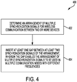
- FIG. 4 shows a block diagram for a method 400 of determining a unified synchronization signal arrangement according to the invention.
- unified synchronization signal logic e.g., an instruction set stored by memory 242 and executable upon controller/processor 240 of gNB 105
- the synchronization signals may, for example, include one or more of the following signals: PSS, SSS, RS, and PBCH signals.
- unified synchronization signal logic causes one or more gaps to be inserted between two or more synchronization signals of the arrangement (e.g., an instruction set stored by memory 242 and executable upon controller/processor 240 of gNB 105 may control transmit processor 220 in insert one or more gaps between two or more synchronization signals to be transmitted by gNB 105).
- the one or more gaps enable the same arrangement of multiple synchronization signals to be used in multiple communication modes that operate utilizing different numerologies, such as communication modes 320-2, 310-4, 310-6 described above in connection with FIG. 3 .
- the one or more gaps among synchronization signals of the arrangement of multiple synchronization signals allow the multiple synchronization signals to be fit in data units of one or more communication blocks (such as communication blocks 320-2, 320-4, 320-6, 320-8 described in FIG. 3 ) and avoid any overlap with units reserved for other control signals in the one or more communication blocks.
- the aforementioned different numerologies utilized by the communication modes may result in differences in the various blocks (e.g., frames) transmitted.
- different numerologies corresponding to subcarrier spacing may provide for differences in symbol lengths as between the signals transmitted by the communication modes.
- a unified synchronization signal such as that shown in the exemplary embodiment illustrated in FIG. 3
- the unified synchronization signal may nevertheless have differences as disposed in the blocks of each such communication mode.
- a unified synchronization signal although having a same predetermined arrangement of synchronization signals transmitted using each communication mode, may be disposed having a different boundary offset in the different communication modes.
- a unified synchronization signal configuration of embodiments as may facilitate detection of the synchronization signals by a network node (e.g., UE), may be adapted to facilitate detection of a communication block of the communication modes.
- FIG. 5 shows a block diagram for indicating a boundary of a communication block for a unified synchronization channel configuration that may be used in wireless network 100. Boundary indicating configurations of embodiments may be used, for example, for communications between gNB 105 and UE 115, between gNBs 105a-c, or between multiple UEs. FIG. 5 shows a configuration for indicating boundaries of communication blocks (e.g., frames, subframes, or slots) for a unified synchronization signal configuration where the same synchronization signal configuration 502 is used for different communication modes 510-2, 510-4, and 510-6 in a wireless communication network.
- communication blocks e.g., frames, subframes, or slots
- the synchronization signal configuration may, for example, have a fixed length in time when used in the multiple communication modes, wherein the fixed length is selected for configuring the synchronization signal configuration for multiple communication modes.
- Embodiments of the synchronization signal configuration may utilize one or more gaps, such as discussed above with reference to FIG. 3 for configuring the synchronization signal configuration for multiple communication modes.
- control signals in communication blocks 520-2, 520-4, 520-6, and 520-8 may include one or more units (e.g., 522) for downlink (from a gNB to a UE) control signals and/or one or more units (e.g., 524) for uplink (from a UE to a gNB) control signals.
- a communication block may represent a frame, two consecutive units in the communication block may represent a subframe (e.g., in a time division duplex (TDD) or frequency division duplex (FDD) system), and one unit in the communication block may represent a slot (e.g., in an FDD system).
- a communication block may represent a subframe or a slot.
- FIG. 5 shows a contiguous configuration of SSB synchronization signals
- other configurations of synchronization signals may be utilized with boundary indication implementations of the present disclosure.
- a split SSB synchronization signal configuration such as that of the exemplary embodiment illustrated in FIG. 3 , may be utilized with communication block boundary indication implementations of the present disclosure.
- each communication mode operates utilizing a different subcarrier spacing
- e.g., communication mode 510-2 operates utilizing a 15 kHz subcarrier spacing
- communication mode 510-4 operates utilizing a 30 kHz subcarrier spacing
- communication mode 510-6 operates utilizing a 60 kHz subcarrier spacing. Consequently, communication blocks 520-2, 520-4, 520-6, and 520-8 for these different communication modes provide different symbol sizes and different offset from the communication block boundaries.
- synchronization signal configuration 502 may include an arrangement of multiple synchronization signals 504 comprising a SSB, which may include, for example, a PSS, SSS, RS, and signals transmitted over a PBCH.
- a SSB of synchronization signal configuration 502 comprises a suite of synchronization signals including a PSS followed by a SSS and a RS (e.g., MRS), which is in turn followed by two PBCH signals.
- synchronization signal configuration 502 starts with a PSS in the illustrated example
- the SSB of synchronization signal configuration 502 may start with any other types of synchronization signals, such as an SSS, RS, PBCH, or the like.
- the SSB of synchronization signal configuration 502 may comprise a suite of synchronization signals including any combination of any number of synchronization signals in any suitable order.
- the SSB of synchronization signal configuration 502 may be placed in different locations relative to the beginning of communication blocks 520-2, 520-4, 520-6, 520-8 in different communication modes 510-2, 510-4, and 510-6.
- synchronization signals are first detected, and then the boundary of a communication block (i.e., the beginning of the communication block) containing the synchronization signals is then determined relative to the position of the synchronization signals. Therefore, a mechanism of embodiments herein that clearly indicates the boundary of a communication block in different communication modes may provide efficient processing and reduce the computational complexity in the system.
- a technique for boundary identification provides information (referred to herein as boundary information) indicating the relative distance between the communication block boundary and the beginning of synchronization signals via at least one of the synchronization signals.
- boundary information information indicating the relative distance between the communication block boundary and the beginning of synchronization signals via at least one of the synchronization signals.
- distances 530-2, 530-4, 530-6 between the beginning of communication blocks 520-2, 520-4, 520-6 and the beginning of the SSB of synchronization signal configuration 502 may be predetermined for each of the communication modes.
- the communication mode of a communication block may be indicated in boundary information included in at least one of the synchronization signals of the SSB of synchronization signal configuration 502 (e.g., one or more of PSS, SSS, RS, and PBCH) according to embodiments of the present disclosure.
- distance 530-2 represents that the beginning of communication block 520-2 is three units (e.g., symbols) from the beginning of the beginning of the SSB of synchronization signal configuration 502 for communication mode 510-2
- distance 530-4 represents that the beginning of communication block 520-4 is five units (e.g., symbols) from the beginning of the SSB of synchronization signal configuration 502 for communication mode 510-4
- distance 530-6 represents that the beginning of communication block 520-6 is two units (e.g., symbols) from the beginning of the beginning of the SSB of synchronization signal configuration 502 for communication mode 510-6.
- the foregoing distances between the beginning of a communication block and the beginning of a SSB are predetermined, and thus may be known a priori by the various nodes of the network (e.g., gNB, UE, etc.).
- the receiver may determine that the communication block starts three units ahead of the beginning the SSB of synchronization signal configuration 502 (which is the beginning of PSS in the illustrated example).
- the receiver may determine that the communication block starts five units ahead of the beginning the SSB of synchronization signal configuration 502.
- the distances 530-2, 530-4, 530-6 between the beginning of communication blocks 520-2, 520-4, 520-6 and the beginning of a SSB of synchronization signal configuration 502 may not be predetermined for each communication modes, such as in embodiments where flexibility in placing a SSB of synchronization signal configuration 502 at any position in a communication block is supported.
- the values of distances 530-2, 530-4, 530-6 with respect to the different communication modes may be indicated in boundary information included in at least one of the synchronization signals of a SSB of synchronization signal configuration 502 (e.g., one or more of PBCH, PSS, SSS, and RS).
- this solution has the advantage of flexibly placing a SSB of synchronization signal configuration 502 at any position in a communication block.
- the beginning of a SSB of synchronization signal configuration 502 may be placed six units after the beginning of a communication block, and such relative distance is indicated through boundary information included in one or more of the synchronization signals (e.g., a PBCH signal) of the SSB.
- a receiving node receives the communication block, it can determine the beginning of the communication block by detecting the beginning of the SSB of synchronization signal configuration 502 and extracting the boundary information comprising the aforementioned distance information from the PBCH signal.
- a receiving node may determine the particular communication mode (e.g., communication mode 510-2, communication mode 510-4, or communication mode 510-6) in use with respect to a communication block using SSB numerology (e.g., dependent on carrier frequency).
- SSB numerology e.g., dependent on carrier frequency
- the communication mode in use does not need to be indicated in one of the synchronization signals.
- embodiments may nevertheless indicate the communication mode of a communication block in boundary information included in at least one of the synchronization signals of synchronization signal configuration 502.
- the boundary information may be derived for each communication mode via SSB index, where the SSB index may be determined by RS and PBCH contents, for example.
- FIG. 6 shows a block diagram for method 600 of indicating a boundary of a communication block that contains a unified synchronization signal arrangement.
- unified synchronization signal logic e.g., an instruction set stored by memory 242 and executable upon controller/processor 240 of gNB 105
- the arrangement of multiple synchronization signals is configured for multiple communication modes (e.g., includes a particular arrangement of synchronization signals, with or without one or more gaps, and a relative distance between the beginning of communication blocks of each of a plurality of communication modes and the beginning of the synchronization signal arrangement to accommodate the synchronization signal arrangement in the communication blocks of each of the plurality of communication modes).
- Each communication mode of the multiple communication modes may, for example, operate using different subcarrier spacing.
- the nodes may include a gNB, a UE, and/or other devices in wireless communication network 100 as described above in connection with FIG. 1 .
- the unified synchronization signal arrangement may include synchronization signal configurations 302, 502 providing SSBs as described above in FIGs. 3 and 5 or any other configurations appropriate for use with respect to the multiple communication modes being accommodated.
- the synchronization signals in SSBs of the synchronization signal arrangement may include one or more of the following signals: PSS, SSS, RS, and/or PBCH signals.
- unified synchronization signal logic causes a relative distance between a beginning of the arrangement of multiple synchronization signals and a beginning of a communication block containing the arrangement of multiple synchronization signals to be indicated via at least one synchronization signal of the arrangement of multiple synchronization signals.
- an instruction set stored by memory 242 and executable upon controller/processor 240 of gNB 105 may control transmit processor 220 in insert boundary information indicating the relative distance into one or more synchronization signals (e.g., PSS, SSS, RS, and/or PBCH signals) of the synchronization signal arrangement.
- synchronization signals e.g., PSS, SSS, RS, and/or PBCH signals
- RS and PBCH together with SSB numerology may be utilized to carry boundary information the, such as to enable boundary information for each communication mode to be derived via SSB index where SSB index is determined by RS and PBCH contents.
- the relative distances may be predetermined for each communication mode (e.g., communication modes 520-2, 510-4, 510-6 described above in connection with FIG. 5 or similar communication modes as present in the configuration of FIG. 3 ). Accordingly, the boundary information inserted into one or more synchronization signals may indicate the communication mode in use, whereby the receiving node may derive the relative distance from the communication mode information and knowledge of the corresponding predetermined relative distance.
- unified synchronization signal logic may determine the communication mode being used with respect to a communication (e.g., one of communication modes 510-2, 510-4, or 510-6 or similar communication modes as present in the configuration of FIG. 3 ) and control a transmit signal processor (e.g., transmit processor 220 of gNB 105) to insert boundary information indicating that particular communication mode into one or more synchronization signals of the synchronization signal arrangement.
- a communication e.g., one of communication modes 510-2, 510-4, or 510-6 or similar communication modes as present in the configuration of FIG. 3
- a transmit signal processor e.g., transmit processor 220 of gNB 105
- the contents of RS and PBCH may be provided with information from which the SSB index may be determined by a receiving node, whereby the SSB index and SSB numerology indicate the communication mode in use.
- the unified synchronization signal logic may control the transmit signal processor to include the synchronization signal arrangement within a communication block (e.g., a frame) with the appropriate relative distance between a beginning of the synchronization signal arrangement and a beginning of the communication block.
- the unified synchronization signal logic may access one or more databases (e.g., a communication mode unified synchronization signal relative distance look up table stored by memory 242 of gNB 105 providing a knowledge base regarding the relative distance from the beginning of the synchronization signal arrangement and a beginning of a communication block containing the synchronization signal arrangement for each of the plurality of communication modes accommodated) to determine an appropriate relative distance (e.g., distances 530-2, 530-4, 530-6 described in FIG. 5 or similar distances as present in the configuration of FIG. 3 ) for the synchronization signal arrangement for the communication mode being used, and then provide appropriate control to implement the relative distance when disposing the synchronization signals of the synchronization signal arrangement in the communication block.
- databases e.g., a communication mode unified synchronization signal relative distance look up table stored by memory 242 of gNB 105 providing a knowledge base regarding the relative distance from the beginning of the synchronization signal arrangement and a beginning of a communication block containing the synchronization signal arrangement
- the relative distance (e.g., distances 530-2, 530-4, 530-6 described in FIG. 5 or similar distances as present in the configuration of FIG. 3 ) is not predetermined. Accordingly, the boundary information inserted into one or more synchronization signals may indicate the value of the relative distance.
- unified synchronization signal logic e.g., an instruction set stored by memory 242 and executable upon controller/processor 240 of gNB 105 may determine the communication mode being used with respect to a communication (e.g., one of communication modes 510-2, 510-4, or 510-6 or similar communication modes as present in the configuration of FIG.
- the unified synchronization signal logic may control a transmit signal processor (e.g., transmit processor 220 of gNB 105) to insert boundary information indicating that particular relative distance into one or more synchronization signals of the synchronization signal arrangement.
- RS and PBCH may be utilized to carry boundary information such as that indicating the relative distance.
- the unified synchronization signal logic may control the transmit signal processor to include the synchronization signal arrangement within a communication block (e.g., a frame) with the appropriate relative distance between a beginning of the synchronization signal arrangement and a beginning of the communication block, as previously determined.
- a communication block e.g., a frame
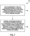
- FIG. 7 shows a block diagram for method 700 of determining a boundary of a communication block that contains a unified synchronization signal arrangement.
- unified synchronization signal logic e.g., an instruction set stored by memory 282 and executable upon controller/processor 280 of UE 115
- a network node monitors one or more channels for synchronization signals (e.g., PSS, SSS, RS, and/or PBCH signals) of an arrangement of multiple synchronization signals to detect the presence of the synchronization signal arrangement in a transmission.
- synchronization signals e.g., PSS, SSS, RS, and/or PBCH signals
- a receive processor may process and analyze received signals to detect one or more synchronization signals, whereby the receive processor provides information regarding the detected synchronization signals to a controller (e.g., controller/processor 280) of the receiving node for determining if a particular arrangement of multiple synchronization signals is present in the received signals (e.g., a synchronization signal arrangement is carried in a received communication block).
- a controller e.g., controller/processor 280
- unified synchronization signal logic determines a relative distance between a beginning of the arrangement of multiple synchronization signals and a beginning of a communication block containing the arrangement of multiple synchronization signals to be indicated via at least one synchronization signal of the arrangement of multiple synchronization signals.
- an instruction set stored by memory 282 and executable upon controller/processor 280 of UE 115 may control receive processor 258 to extract boundary information indicating the relative distance from one or more synchronization signals (e.g., PSS, SSS, RS, and/or PBCH signals) of the synchronization signal arrangement and provide the boundary information to controller/processor 280.
- the unified synchronization signal logic may utilize the boundary information extracted from the one or more synchronization signals to determine the relative distance between the beginning of the detected synchronization signal arrangement and the beginning of a communication block in which the synchronization signal arrangement was received.
- the relative distances may be predetermined for each communication mode (e.g., communication modes 520-2, 510-4, 510-6 described above in connection with FIG. 5 or similar communication modes as present in the configuration of FIG. 3 ). Accordingly, the boundary information extracted from one or more synchronization signals may indicate the communication mode in use, whereby the receiving node may derive the relative distance from the communication mode information and knowledge of the corresponding predetermined relative distance.
- unified synchronization signal logic may analyze the extracted boundary information to determine the communication mode being used with respect to a received communication block (e.g., one of communication modes 510-2, 510-4, or 510-6 or similar communication modes as present in the configuration of FIG.
- the unified synchronization signal logic may provide appropriate control to utilize the relative distance information for detecting the beginning of the communication block, such as for extracting data therefrom.
- the relative distance (e.g., distances 530-2, 530-4, 530-6 described in FIG. 5 or similar distances as present in the configuration of FIG. 3 ) is not predetermined. Accordingly, the boundary information extracted from one or more synchronization signals may indicate the value of the relative distance.
- Unified synchronization signal logic e.g., an instruction set stored by memory 282 and executable upon controller/processor 280 of UE 115
- the receive processor e.g., receive processor 258
- the unified synchronization signal logic may provide appropriate control to utilize the relative distance information for detecting the beginning of the communication block, such as for extracting data therefrom.
- the functional blocks and modules described herein may comprise processors, electronics devices, hardware devices, electronics components, logical circuits, memories, software codes, firmware codes, etc., or any combination thereof.
- DSP digital signal processor
- ASIC application specific integrated circuit
- FPGA field programmable gate array
- a general-purpose processor may be a microprocessor, but in the alternative, the processor may be any conventional processor, controller, microcontroller, or state machine.
- a processor may also be implemented as a combination of computing devices, e.g., a combination of a DSP and a microprocessor, a plurality of microprocessors, one or more microprocessors in conjunction with a DSP core, or any other such configuration.
- a software module may reside in RAM memory, flash memory, ROM memory, EPROM memory, EEPROM memory, registers, hard disk, a removable disk, a CD-ROM, or any other form of storage medium known in the art.
- An exemplary storage medium is coupled to the processor such that the processor can read information from, and write information to, the storage medium.
- the storage medium may be integral to the processor.
- the processor and the storage medium may reside in an ASIC.
- the ASIC may reside in a user terminal.
- the processor and the storage medium may reside as discrete components in a user terminal.
- the functions described may be implemented in hardware, software, firmware, or any combination thereof. If implemented in software, the functions may be stored on or transmitted over as one or more instructions or code on a computer-readable medium.
- Computer-readable media includes both computer storage media and communication media including any medium that facilitates transfer of a computer program from one place to another. Computer-readable storage media may be any available media that can be accessed by a general purpose or special purpose computer.
- such computer-readable media can comprise RAM, ROM, EEPROM, CD-ROM or other optical disk storage, magnetic disk storage or other magnetic storage devices, or any other medium that can be used to carry or store desired program code means in the form of instructions or data structures and that can be accessed by a general-purpose or special-purpose computer, or a general-purpose or special-purpose processor.
- a connection may be properly termed a computer-readable medium.
- the software is transmitted from a website, server, or other remote source using a coaxial cable, fiber optic cable, twisted pair, or digital subscriber line (DSL), then the coaxial cable, fiber optic cable, twisted pair, or DSL, are included in the definition of medium.
- DSL digital subscriber line
- Disk and disc includes compact disc (CD), laser disc, optical disc, digital versatile disc (DVD), hard disk, solid state disk, and blu-ray disc where disks usually reproduce data magnetically, while discs reproduce data optically with lasers. Combinations of the above should also be included within the scope of computer-readable media.
- the term "and/or,” when used in a list of two or more items, means that any one of the listed items can be employed by itself, or any combination of two or more of the listed items can be employed.
- the composition can contain A alone; B alone; C alone; A and B in combination; A and C in combination; B and C in combination; or A, B, and C in combination.
Landscapes
- Engineering & Computer Science (AREA)
- Signal Processing (AREA)
- Computer Networks & Wireless Communication (AREA)
- Physics & Mathematics (AREA)
- Mathematical Physics (AREA)
- Databases & Information Systems (AREA)
- Mobile Radio Communication Systems (AREA)
- Time-Division Multiplex Systems (AREA)
Priority Applications (2)
| Application Number | Priority Date | Filing Date | Title |
|---|---|---|---|
| SI201730901T SI3539249T1 (sl) | 2016-11-08 | 2017-11-08 | Oblika enotnega sinhronizacijskega kanala, ki se uporablja v različnih načinih komunikacije |
| EP21162065.3A EP3855672B1 (en) | 2016-11-08 | 2017-11-08 | Unified synchronization channel design used in different communication modes |
Applications Claiming Priority (4)
| Application Number | Priority Date | Filing Date | Title |
|---|---|---|---|
| US201662419409P | 2016-11-08 | 2016-11-08 | |
| US201662419398P | 2016-11-08 | 2016-11-08 | |
| US15/806,210 US10531410B2 (en) | 2016-11-08 | 2017-11-07 | Unified synchronization channel design used in different communication modes |
| PCT/US2017/060653 WO2018089505A1 (en) | 2016-11-08 | 2017-11-08 | Unified synchronization channel design used in different communication modes |
Related Child Applications (2)
| Application Number | Title | Priority Date | Filing Date |
|---|---|---|---|
| EP21162065.3A Division EP3855672B1 (en) | 2016-11-08 | 2017-11-08 | Unified synchronization channel design used in different communication modes |
| EP21162065.3A Division-Into EP3855672B1 (en) | 2016-11-08 | 2017-11-08 | Unified synchronization channel design used in different communication modes |
Publications (2)
| Publication Number | Publication Date |
|---|---|
| EP3539249A1 EP3539249A1 (en) | 2019-09-18 |
| EP3539249B1 true EP3539249B1 (en) | 2021-08-25 |
Family
ID=62108968
Family Applications (2)
| Application Number | Title | Priority Date | Filing Date |
|---|---|---|---|
| EP17804380.8A Active EP3539249B1 (en) | 2016-11-08 | 2017-11-08 | Unified synchronization channel design used in different communication modes |
| EP21162065.3A Active EP3855672B1 (en) | 2016-11-08 | 2017-11-08 | Unified synchronization channel design used in different communication modes |
Family Applications After (1)
| Application Number | Title | Priority Date | Filing Date |
|---|---|---|---|
| EP21162065.3A Active EP3855672B1 (en) | 2016-11-08 | 2017-11-08 | Unified synchronization channel design used in different communication modes |
Country Status (13)
| Country | Link |
|---|---|
| US (1) | US10531410B2 (enExample) |
| EP (2) | EP3539249B1 (enExample) |
| JP (2) | JP7004710B2 (enExample) |
| KR (2) | KR102553415B1 (enExample) |
| CN (2) | CN109952737B (enExample) |
| BR (1) | BR112019009225A2 (enExample) |
| CA (1) | CA3039067A1 (enExample) |
| DK (1) | DK3539249T3 (enExample) |
| ES (1) | ES2890243T3 (enExample) |
| HU (1) | HUE055995T2 (enExample) |
| SI (1) | SI3539249T1 (enExample) |
| TW (1) | TWI761388B (enExample) |
| WO (1) | WO2018089505A1 (enExample) |
Families Citing this family (13)
| Publication number | Priority date | Publication date | Assignee | Title |
|---|---|---|---|---|
| US10560343B1 (en) | 2012-07-06 | 2020-02-11 | Cradlepoint, Inc. | People centric management of cloud networks via GUI |
| US10135677B1 (en) | 2012-07-06 | 2018-11-20 | Cradlepoint, Inc. | Deployment of network-related features over cloud network |
| US10601653B2 (en) | 2012-07-06 | 2020-03-24 | Cradlepoint, Inc. | Implicit traffic engineering |
| US10110417B1 (en) | 2012-07-06 | 2018-10-23 | Cradlepoint, Inc. | Private networks overlaid on cloud infrastructure |
| US10177957B1 (en) | 2012-07-06 | 2019-01-08 | Cradlepoint, Inc. | Connecting a cloud network to the internet |
| US10880162B1 (en) | 2012-07-06 | 2020-12-29 | Cradlepoint, Inc. | Linking logical broadcast domains |
| US11419083B2 (en) | 2016-11-08 | 2022-08-16 | Qualcomm Incorporated | Unified synchronization channel design used in different communication modes |
| US10356734B2 (en) * | 2016-11-30 | 2019-07-16 | Qualcomm Incorporated | Synchronization signal options for 5G/new radio |
| WO2018137231A1 (en) * | 2017-01-26 | 2018-08-02 | Qualcomm Incorporated | Broadcast channel encoding and decoding |
| CN110784905B (zh) | 2018-07-25 | 2021-11-16 | 财团法人工业技术研究院 | 网络接入方法和使用网络接入方法的用户设备 |
| CN112578692B (zh) * | 2019-09-27 | 2022-04-15 | 北京东土科技股份有限公司 | 工业总线通信方法、装置、计算机设备及存储介质 |
| US20230345397A1 (en) * | 2022-04-21 | 2023-10-26 | Qualcomm Incorporated | Configurable synchronization signal and physical broadcast channel block pattern |
| WO2025025047A1 (zh) * | 2023-07-31 | 2025-02-06 | 华为技术有限公司 | 通信方法和装置 |
Family Cites Families (10)
| Publication number | Priority date | Publication date | Assignee | Title |
|---|---|---|---|---|
| US8908504B2 (en) * | 2011-07-01 | 2014-12-09 | Qualcomm Incorporated | Pre-agreed radio link failure recovery channel sequence |
| EP2995054B1 (en) | 2013-05-10 | 2017-03-22 | Telefonaktiebolaget LM Ericsson (publ) | Synchronization sequences and carrier type detection |
| CN108419288B (zh) * | 2013-06-13 | 2020-11-06 | Lg电子株式会社 | 发送用于装置对装置链路的同步信号的方法及用户设备 |
| CN105493582A (zh) * | 2013-08-29 | 2016-04-13 | Lg电子株式会社 | 用于在支持高频带的无线接入系统中在每个步骤中检测上行链路同步信号的方法和设备 |
| CN105981454B (zh) * | 2014-01-26 | 2019-11-15 | Lg电子株式会社 | 在支持设备到设备通信的无线通信系统中发送同步信号和同步信道的方法及其装置 |
| NO2705215T3 (enExample) * | 2014-01-31 | 2018-02-17 | ||
| EP3117638A1 (en) * | 2014-03-12 | 2017-01-18 | Telefonaktiebolaget LM Ericsson (publ) | Device-to-device communication in a cellular communication system |
| US20170295576A1 (en) | 2014-09-26 | 2017-10-12 | Kyocera Corporation | Base station and mobile station |
| JP6637164B2 (ja) | 2015-09-08 | 2020-01-29 | エルジー エレクトロニクス インコーポレイティド | 狭帯域モノのインターネットを支援する無線接続システムにおいて下りリンク物理放送チャネル受信方法及び装置 |
| WO2018031644A1 (en) * | 2016-08-10 | 2018-02-15 | Intel IP Corporation | Synchronization signals for multiple numerologies |
-
2017
- 2017-11-07 US US15/806,210 patent/US10531410B2/en active Active
- 2017-11-08 KR KR1020197012644A patent/KR102553415B1/ko active Active
- 2017-11-08 HU HUE17804380A patent/HUE055995T2/hu unknown
- 2017-11-08 CN CN201780068483.0A patent/CN109952737B/zh active Active
- 2017-11-08 ES ES17804380T patent/ES2890243T3/es active Active
- 2017-11-08 CN CN202210817611.XA patent/CN115103435B/zh active Active
- 2017-11-08 EP EP17804380.8A patent/EP3539249B1/en active Active
- 2017-11-08 DK DK17804380.8T patent/DK3539249T3/da active
- 2017-11-08 KR KR1020227045734A patent/KR102596588B1/ko active Active
- 2017-11-08 WO PCT/US2017/060653 patent/WO2018089505A1/en not_active Ceased
- 2017-11-08 CA CA3039067A patent/CA3039067A1/en active Pending
- 2017-11-08 EP EP21162065.3A patent/EP3855672B1/en active Active
- 2017-11-08 SI SI201730901T patent/SI3539249T1/sl unknown
- 2017-11-08 BR BR112019009225A patent/BR112019009225A2/pt unknown
- 2017-11-08 JP JP2019522425A patent/JP7004710B2/ja active Active
- 2017-11-09 TW TW106138753A patent/TWI761388B/zh active
-
2021
- 2021-12-28 JP JP2021214393A patent/JP7384892B2/ja active Active
Non-Patent Citations (1)
| Title |
|---|
| None * |
Also Published As
| Publication number | Publication date |
|---|---|
| CN109952737A (zh) | 2019-06-28 |
| KR102553415B1 (ko) | 2023-07-07 |
| TW201919424A (zh) | 2019-05-16 |
| JP2020502868A (ja) | 2020-01-23 |
| JP7384892B2 (ja) | 2023-11-21 |
| CN109952737B (zh) | 2022-07-19 |
| BR112019009225A2 (pt) | 2019-07-16 |
| JP2022058463A (ja) | 2022-04-12 |
| WO2018089505A1 (en) | 2018-05-17 |
| KR20190073407A (ko) | 2019-06-26 |
| EP3855672B1 (en) | 2023-08-30 |
| CA3039067A1 (en) | 2018-05-17 |
| TWI761388B (zh) | 2022-04-21 |
| EP3539249A1 (en) | 2019-09-18 |
| CN115103435A (zh) | 2022-09-23 |
| KR20230007549A (ko) | 2023-01-12 |
| DK3539249T3 (da) | 2021-09-20 |
| US10531410B2 (en) | 2020-01-07 |
| JP7004710B2 (ja) | 2022-01-21 |
| KR102596588B1 (ko) | 2023-10-31 |
| HUE055995T2 (hu) | 2022-01-28 |
| ES2890243T3 (es) | 2022-01-18 |
| CN115103435B (zh) | 2024-03-15 |
| SI3539249T1 (sl) | 2021-11-30 |
| US20180139713A1 (en) | 2018-05-17 |
| EP3855672A1 (en) | 2021-07-28 |
Similar Documents
| Publication | Publication Date | Title |
|---|---|---|
| EP3539249B1 (en) | Unified synchronization channel design used in different communication modes | |
| EP3794745B1 (en) | Use-cases and constraints on multiple srs resource sets for antenna switching in nr rel-15 | |
| EP3577840B1 (en) | Control resource set group design for improved communications devices, systems, and networks | |
| CA3039266C (en) | Ul waveform during rach procedure and autonomous ul transmission | |
| EP3777443B1 (en) | Multi-carrier enhancements for improving reliability in urllc-u | |
| US11419083B2 (en) | Unified synchronization channel design used in different communication modes | |
| KR102737838B1 (ko) | 뉴 라디오 (nr) 나머지 최소 시스템 정보 (rmsi) 다중화 및 주기성 고려 | |
| EP4033688B1 (en) | Support of wideband physical resource group (prg) in long term evolution (lte) |
Legal Events
| Date | Code | Title | Description |
|---|---|---|---|
| STAA | Information on the status of an ep patent application or granted ep patent |
Free format text: STATUS: UNKNOWN |
|
| STAA | Information on the status of an ep patent application or granted ep patent |
Free format text: STATUS: THE INTERNATIONAL PUBLICATION HAS BEEN MADE |
|
| PUAI | Public reference made under article 153(3) epc to a published international application that has entered the european phase |
Free format text: ORIGINAL CODE: 0009012 |
|
| STAA | Information on the status of an ep patent application or granted ep patent |
Free format text: STATUS: REQUEST FOR EXAMINATION WAS MADE |
|
| 17P | Request for examination filed |
Effective date: 20190405 |
|
| AK | Designated contracting states |
Kind code of ref document: A1 Designated state(s): AL AT BE BG CH CY CZ DE DK EE ES FI FR GB GR HR HU IE IS IT LI LT LU LV MC MK MT NL NO PL PT RO RS SE SI SK SM TR |
|
| AX | Request for extension of the european patent |
Extension state: BA ME |
|
| DAV | Request for validation of the european patent (deleted) | ||
| DAX | Request for extension of the european patent (deleted) | ||
| GRAP | Despatch of communication of intention to grant a patent |
Free format text: ORIGINAL CODE: EPIDOSNIGR1 |
|
| STAA | Information on the status of an ep patent application or granted ep patent |
Free format text: STATUS: GRANT OF PATENT IS INTENDED |
|
| INTG | Intention to grant announced |
Effective date: 20201207 |
|
| GRAJ | Information related to disapproval of communication of intention to grant by the applicant or resumption of examination proceedings by the epo deleted |
Free format text: ORIGINAL CODE: EPIDOSDIGR1 |
|
| STAA | Information on the status of an ep patent application or granted ep patent |
Free format text: STATUS: REQUEST FOR EXAMINATION WAS MADE |
|
| GRAP | Despatch of communication of intention to grant a patent |
Free format text: ORIGINAL CODE: EPIDOSNIGR1 |
|
| STAA | Information on the status of an ep patent application or granted ep patent |
Free format text: STATUS: GRANT OF PATENT IS INTENDED |
|
| INTC | Intention to grant announced (deleted) | ||
| INTG | Intention to grant announced |
Effective date: 20210414 |
|
| GRAS | Grant fee paid |
Free format text: ORIGINAL CODE: EPIDOSNIGR3 |
|
| GRAA | (expected) grant |
Free format text: ORIGINAL CODE: 0009210 |
|
| STAA | Information on the status of an ep patent application or granted ep patent |
Free format text: STATUS: THE PATENT HAS BEEN GRANTED |
|
| AK | Designated contracting states |
Kind code of ref document: B1 Designated state(s): AL AT BE BG CH CY CZ DE DK EE ES FI FR GB GR HR HU IE IS IT LI LT LU LV MC MK MT NL NO PL PT RO RS SE SI SK SM TR |
|
| REG | Reference to a national code |
Ref country code: CH Ref legal event code: EP |
|
| REG | Reference to a national code |
Ref country code: DE Ref legal event code: R096 Ref document number: 602017044828 Country of ref document: DE |
|
| REG | Reference to a national code |
Ref country code: IE Ref legal event code: FG4D Ref country code: AT Ref legal event code: REF Ref document number: 1424905 Country of ref document: AT Kind code of ref document: T Effective date: 20210915 |
|
| REG | Reference to a national code |
Ref country code: DK Ref legal event code: T3 Effective date: 20210915 |
|
| REG | Reference to a national code |
Ref country code: FI Ref legal event code: FGE |
|
| REG | Reference to a national code |
Ref country code: SE Ref legal event code: TRGR |
|
| REG | Reference to a national code |
Ref country code: GR Ref legal event code: EP Ref document number: 20210402518 Country of ref document: GR Effective date: 20211013 |
|
| REG | Reference to a national code |
Ref country code: NO Ref legal event code: T2 Effective date: 20210825 |
|
| REG | Reference to a national code |
Ref country code: LT Ref legal event code: MG9D |
|
| REG | Reference to a national code |
Ref country code: NL Ref legal event code: FP |
|
| REG | Reference to a national code |
Ref country code: AT Ref legal event code: MK05 Ref document number: 1424905 Country of ref document: AT Kind code of ref document: T Effective date: 20210825 |
|
| REG | Reference to a national code |
Ref country code: ES Ref legal event code: FG2A Ref document number: 2890243 Country of ref document: ES Kind code of ref document: T3 Effective date: 20220118 |
|
| REG | Reference to a national code |
Ref country code: HU Ref legal event code: AG4A Ref document number: E055995 Country of ref document: HU |
|
| PG25 | Lapsed in a contracting state [announced via postgrant information from national office to epo] |
Ref country code: RS Free format text: LAPSE BECAUSE OF FAILURE TO SUBMIT A TRANSLATION OF THE DESCRIPTION OR TO PAY THE FEE WITHIN THE PRESCRIBED TIME-LIMIT Effective date: 20210825 Ref country code: HR Free format text: LAPSE BECAUSE OF FAILURE TO SUBMIT A TRANSLATION OF THE DESCRIPTION OR TO PAY THE FEE WITHIN THE PRESCRIBED TIME-LIMIT Effective date: 20210825 Ref country code: LT Free format text: LAPSE BECAUSE OF FAILURE TO SUBMIT A TRANSLATION OF THE DESCRIPTION OR TO PAY THE FEE WITHIN THE PRESCRIBED TIME-LIMIT Effective date: 20210825 Ref country code: BG Free format text: LAPSE BECAUSE OF FAILURE TO SUBMIT A TRANSLATION OF THE DESCRIPTION OR TO PAY THE FEE WITHIN THE PRESCRIBED TIME-LIMIT Effective date: 20211125 Ref country code: AT Free format text: LAPSE BECAUSE OF FAILURE TO SUBMIT A TRANSLATION OF THE DESCRIPTION OR TO PAY THE FEE WITHIN THE PRESCRIBED TIME-LIMIT Effective date: 20210825 Ref country code: PT Free format text: LAPSE BECAUSE OF FAILURE TO SUBMIT A TRANSLATION OF THE DESCRIPTION OR TO PAY THE FEE WITHIN THE PRESCRIBED TIME-LIMIT Effective date: 20211227 |
|
| PG25 | Lapsed in a contracting state [announced via postgrant information from national office to epo] |
Ref country code: PL Free format text: LAPSE BECAUSE OF FAILURE TO SUBMIT A TRANSLATION OF THE DESCRIPTION OR TO PAY THE FEE WITHIN THE PRESCRIBED TIME-LIMIT Effective date: 20210825 Ref country code: LV Free format text: LAPSE BECAUSE OF FAILURE TO SUBMIT A TRANSLATION OF THE DESCRIPTION OR TO PAY THE FEE WITHIN THE PRESCRIBED TIME-LIMIT Effective date: 20210825 |
|
| REG | Reference to a national code |
Ref country code: DE Ref legal event code: R097 Ref document number: 602017044828 Country of ref document: DE |
|
| PG25 | Lapsed in a contracting state [announced via postgrant information from national office to epo] |
Ref country code: SM Free format text: LAPSE BECAUSE OF FAILURE TO SUBMIT A TRANSLATION OF THE DESCRIPTION OR TO PAY THE FEE WITHIN THE PRESCRIBED TIME-LIMIT Effective date: 20210825 Ref country code: SK Free format text: LAPSE BECAUSE OF FAILURE TO SUBMIT A TRANSLATION OF THE DESCRIPTION OR TO PAY THE FEE WITHIN THE PRESCRIBED TIME-LIMIT Effective date: 20210825 Ref country code: RO Free format text: LAPSE BECAUSE OF FAILURE TO SUBMIT A TRANSLATION OF THE DESCRIPTION OR TO PAY THE FEE WITHIN THE PRESCRIBED TIME-LIMIT Effective date: 20210825 Ref country code: EE Free format text: LAPSE BECAUSE OF FAILURE TO SUBMIT A TRANSLATION OF THE DESCRIPTION OR TO PAY THE FEE WITHIN THE PRESCRIBED TIME-LIMIT Effective date: 20210825 Ref country code: CZ Free format text: LAPSE BECAUSE OF FAILURE TO SUBMIT A TRANSLATION OF THE DESCRIPTION OR TO PAY THE FEE WITHIN THE PRESCRIBED TIME-LIMIT Effective date: 20210825 Ref country code: AL Free format text: LAPSE BECAUSE OF FAILURE TO SUBMIT A TRANSLATION OF THE DESCRIPTION OR TO PAY THE FEE WITHIN THE PRESCRIBED TIME-LIMIT Effective date: 20210825 |
|
| PG25 | Lapsed in a contracting state [announced via postgrant information from national office to epo] |
Ref country code: MC Free format text: LAPSE BECAUSE OF FAILURE TO SUBMIT A TRANSLATION OF THE DESCRIPTION OR TO PAY THE FEE WITHIN THE PRESCRIBED TIME-LIMIT Effective date: 20210825 |
|
| PLBE | No opposition filed within time limit |
Free format text: ORIGINAL CODE: 0009261 |
|
| STAA | Information on the status of an ep patent application or granted ep patent |
Free format text: STATUS: NO OPPOSITION FILED WITHIN TIME LIMIT |
|
| PG25 | Lapsed in a contracting state [announced via postgrant information from national office to epo] |
Ref country code: LU Free format text: LAPSE BECAUSE OF NON-PAYMENT OF DUE FEES Effective date: 20211108 |
|
| 26N | No opposition filed |
Effective date: 20220527 |
|
| PG25 | Lapsed in a contracting state [announced via postgrant information from national office to epo] |
Ref country code: CY Free format text: LAPSE BECAUSE OF FAILURE TO SUBMIT A TRANSLATION OF THE DESCRIPTION OR TO PAY THE FEE WITHIN THE PRESCRIBED TIME-LIMIT Effective date: 20210825 |
|
| PG25 | Lapsed in a contracting state [announced via postgrant information from national office to epo] |
Ref country code: MK Free format text: LAPSE BECAUSE OF FAILURE TO SUBMIT A TRANSLATION OF THE DESCRIPTION OR TO PAY THE FEE WITHIN THE PRESCRIBED TIME-LIMIT Effective date: 20210825 |
|
| PG25 | Lapsed in a contracting state [announced via postgrant information from national office to epo] |
Ref country code: MT Free format text: LAPSE BECAUSE OF FAILURE TO SUBMIT A TRANSLATION OF THE DESCRIPTION OR TO PAY THE FEE WITHIN THE PRESCRIBED TIME-LIMIT Effective date: 20210825 |
|
| PGFP | Annual fee paid to national office [announced via postgrant information from national office to epo] |
Ref country code: DE Payment date: 20241010 Year of fee payment: 8 |
|
| PGFP | Annual fee paid to national office [announced via postgrant information from national office to epo] |
Ref country code: NO Payment date: 20241028 Year of fee payment: 8 |
|
| PGFP | Annual fee paid to national office [announced via postgrant information from national office to epo] |
Ref country code: DK Payment date: 20241029 Year of fee payment: 8 |
|
| PGFP | Annual fee paid to national office [announced via postgrant information from national office to epo] |
Ref country code: BE Payment date: 20241011 Year of fee payment: 8 Ref country code: FI Payment date: 20241029 Year of fee payment: 8 Ref country code: GR Payment date: 20241029 Year of fee payment: 8 |
|
| PGFP | Annual fee paid to national office [announced via postgrant information from national office to epo] |
Ref country code: GB Payment date: 20241010 Year of fee payment: 8 |
|
| PGFP | Annual fee paid to national office [announced via postgrant information from national office to epo] |
Ref country code: FR Payment date: 20241010 Year of fee payment: 8 |
|
| PGFP | Annual fee paid to national office [announced via postgrant information from national office to epo] |
Ref country code: IE Payment date: 20241028 Year of fee payment: 8 |
|
| PGFP | Annual fee paid to national office [announced via postgrant information from national office to epo] |
Ref country code: IT Payment date: 20241111 Year of fee payment: 8 Ref country code: ES Payment date: 20241212 Year of fee payment: 8 |
|
| PGFP | Annual fee paid to national office [announced via postgrant information from national office to epo] |
Ref country code: SE Payment date: 20241108 Year of fee payment: 8 |
|
| PGFP | Annual fee paid to national office [announced via postgrant information from national office to epo] |
Ref country code: CH Payment date: 20241201 Year of fee payment: 8 |
|
| PGFP | Annual fee paid to national office [announced via postgrant information from national office to epo] |
Ref country code: TR Payment date: 20241015 Year of fee payment: 8 |
|
| PGFP | Annual fee paid to national office [announced via postgrant information from national office to epo] |
Ref country code: SI Payment date: 20241011 Year of fee payment: 8 |
|
| PGFP | Annual fee paid to national office [announced via postgrant information from national office to epo] |
Ref country code: NL Payment date: 20251015 Year of fee payment: 9 |
|
| REG | Reference to a national code |
Ref country code: CH Ref legal event code: U11 Free format text: ST27 STATUS EVENT CODE: U-0-0-U10-U11 (AS PROVIDED BY THE NATIONAL OFFICE) Effective date: 20251201 |
|
| PGFP | Annual fee paid to national office [announced via postgrant information from national office to epo] |
Ref country code: HU Payment date: 20251106 Year of fee payment: 9 |