EP3538229B1 - Physiotherapeutisches stufen- und neigungssystem - Google Patents
Physiotherapeutisches stufen- und neigungssystem Download PDFInfo
- Publication number
- EP3538229B1 EP3538229B1 EP17869513.6A EP17869513A EP3538229B1 EP 3538229 B1 EP3538229 B1 EP 3538229B1 EP 17869513 A EP17869513 A EP 17869513A EP 3538229 B1 EP3538229 B1 EP 3538229B1
- Authority
- EP
- European Patent Office
- Prior art keywords
- sensor
- sensing
- patient
- ramp
- deployed
- Prior art date
- Legal status (The legal status is an assumption and is not a legal conclusion. Google has not performed a legal analysis and makes no representation as to the accuracy of the status listed.)
- Active
Links
Images




Classifications
-
- A—HUMAN NECESSITIES
- A63—SPORTS; GAMES; AMUSEMENTS
- A63B—APPARATUS FOR PHYSICAL TRAINING, GYMNASTICS, SWIMMING, CLIMBING, OR FENCING; BALL GAMES; TRAINING EQUIPMENT
- A63B23/00—Exercising apparatus specially adapted for particular parts of the body
- A63B23/035—Exercising apparatus specially adapted for particular parts of the body for limbs, i.e. upper or lower limbs, e.g. simultaneously
- A63B23/04—Exercising apparatus specially adapted for particular parts of the body for limbs, i.e. upper or lower limbs, e.g. simultaneously for lower limbs
- A63B23/0405—Exercising apparatus specially adapted for particular parts of the body for limbs, i.e. upper or lower limbs, e.g. simultaneously for lower limbs involving a bending of the knee and hip joints simultaneously
- A63B23/0458—Step exercisers without moving parts
-
- A—HUMAN NECESSITIES
- A63—SPORTS; GAMES; AMUSEMENTS
- A63B—APPARATUS FOR PHYSICAL TRAINING, GYMNASTICS, SWIMMING, CLIMBING, OR FENCING; BALL GAMES; TRAINING EQUIPMENT
- A63B23/00—Exercising apparatus specially adapted for particular parts of the body
- A63B23/035—Exercising apparatus specially adapted for particular parts of the body for limbs, i.e. upper or lower limbs, e.g. simultaneously
- A63B23/04—Exercising apparatus specially adapted for particular parts of the body for limbs, i.e. upper or lower limbs, e.g. simultaneously for lower limbs
- A63B23/0405—Exercising apparatus specially adapted for particular parts of the body for limbs, i.e. upper or lower limbs, e.g. simultaneously for lower limbs involving a bending of the knee and hip joints simultaneously
- A63B23/0464—Walk exercisers without moving parts
-
- A—HUMAN NECESSITIES
- A61—MEDICAL OR VETERINARY SCIENCE; HYGIENE
- A61B—DIAGNOSIS; SURGERY; IDENTIFICATION
- A61B5/00—Measuring for diagnostic purposes; Identification of persons
- A61B5/103—Measuring devices for testing the shape, pattern, colour, size or movement of the body or parts thereof, for diagnostic purposes
- A61B5/11—Measuring movement of the entire body or parts thereof, e.g. head or hand tremor or mobility of a limb
-
- A—HUMAN NECESSITIES
- A61—MEDICAL OR VETERINARY SCIENCE; HYGIENE
- A61H—PHYSICAL THERAPY APPARATUS, e.g. DEVICES FOR LOCATING OR STIMULATING REFLEX POINTS IN THE BODY; ARTIFICIAL RESPIRATION; MASSAGE; BATHING DEVICES FOR SPECIAL THERAPEUTIC OR HYGIENIC PURPOSES OR SPECIFIC PARTS OF THE BODY
- A61H3/00—Appliances for aiding patients or disabled persons to walk about
-
- A—HUMAN NECESSITIES
- A63—SPORTS; GAMES; AMUSEMENTS
- A63B—APPARATUS FOR PHYSICAL TRAINING, GYMNASTICS, SWIMMING, CLIMBING, OR FENCING; BALL GAMES; TRAINING EQUIPMENT
- A63B22/00—Exercising apparatus specially adapted for conditioning the cardio-vascular system, for training agility or co-ordination of movements
- A63B22/04—Exercising apparatus specially adapted for conditioning the cardio-vascular system, for training agility or co-ordination of movements with movable multiple steps, i.e. more than one step per limb, e.g. steps mounted on endless loops, endless ladders
-
- A—HUMAN NECESSITIES
- A63—SPORTS; GAMES; AMUSEMENTS
- A63B—APPARATUS FOR PHYSICAL TRAINING, GYMNASTICS, SWIMMING, CLIMBING, OR FENCING; BALL GAMES; TRAINING EQUIPMENT
- A63B23/00—Exercising apparatus specially adapted for particular parts of the body
- A63B23/035—Exercising apparatus specially adapted for particular parts of the body for limbs, i.e. upper or lower limbs, e.g. simultaneously
- A63B23/04—Exercising apparatus specially adapted for particular parts of the body for limbs, i.e. upper or lower limbs, e.g. simultaneously for lower limbs
-
- A—HUMAN NECESSITIES
- A63—SPORTS; GAMES; AMUSEMENTS
- A63B—APPARATUS FOR PHYSICAL TRAINING, GYMNASTICS, SWIMMING, CLIMBING, OR FENCING; BALL GAMES; TRAINING EQUIPMENT
- A63B24/00—Electric or electronic controls for exercising apparatus of preceding groups; Controlling or monitoring of exercises, sportive games, training or athletic performances
-
- A—HUMAN NECESSITIES
- A63—SPORTS; GAMES; AMUSEMENTS
- A63B—APPARATUS FOR PHYSICAL TRAINING, GYMNASTICS, SWIMMING, CLIMBING, OR FENCING; BALL GAMES; TRAINING EQUIPMENT
- A63B24/00—Electric or electronic controls for exercising apparatus of preceding groups; Controlling or monitoring of exercises, sportive games, training or athletic performances
- A63B24/0087—Electric or electronic controls for exercising apparatus of groups A63B21/00 - A63B23/00, e.g. controlling load
-
- A—HUMAN NECESSITIES
- A63—SPORTS; GAMES; AMUSEMENTS
- A63B—APPARATUS FOR PHYSICAL TRAINING, GYMNASTICS, SWIMMING, CLIMBING, OR FENCING; BALL GAMES; TRAINING EQUIPMENT
- A63B71/00—Games or sports accessories not covered in groups A63B1/00 - A63B69/00
- A63B71/06—Indicating or scoring devices for games or players, or for other sports activities
- A63B2071/0675—Input for modifying training controls during workout
-
- A—HUMAN NECESSITIES
- A63—SPORTS; GAMES; AMUSEMENTS
- A63B—APPARATUS FOR PHYSICAL TRAINING, GYMNASTICS, SWIMMING, CLIMBING, OR FENCING; BALL GAMES; TRAINING EQUIPMENT
- A63B2213/00—Exercising combined with therapy
-
- A—HUMAN NECESSITIES
- A63—SPORTS; GAMES; AMUSEMENTS
- A63B—APPARATUS FOR PHYSICAL TRAINING, GYMNASTICS, SWIMMING, CLIMBING, OR FENCING; BALL GAMES; TRAINING EQUIPMENT
- A63B2220/00—Measuring of physical parameters relating to sporting activity
- A63B2220/10—Positions
- A63B2220/13—Relative positions
-
- A—HUMAN NECESSITIES
- A63—SPORTS; GAMES; AMUSEMENTS
- A63B—APPARATUS FOR PHYSICAL TRAINING, GYMNASTICS, SWIMMING, CLIMBING, OR FENCING; BALL GAMES; TRAINING EQUIPMENT
- A63B2220/00—Measuring of physical parameters relating to sporting activity
- A63B2220/50—Force related parameters
- A63B2220/51—Force
- A63B2220/52—Weight, e.g. weight distribution
-
- A—HUMAN NECESSITIES
- A63—SPORTS; GAMES; AMUSEMENTS
- A63B—APPARATUS FOR PHYSICAL TRAINING, GYMNASTICS, SWIMMING, CLIMBING, OR FENCING; BALL GAMES; TRAINING EQUIPMENT
- A63B2220/00—Measuring of physical parameters relating to sporting activity
- A63B2220/62—Time or time measurement used for time reference, time stamp, master time or clock signal
-
- A—HUMAN NECESSITIES
- A63—SPORTS; GAMES; AMUSEMENTS
- A63B—APPARATUS FOR PHYSICAL TRAINING, GYMNASTICS, SWIMMING, CLIMBING, OR FENCING; BALL GAMES; TRAINING EQUIPMENT
- A63B2220/00—Measuring of physical parameters relating to sporting activity
- A63B2220/80—Special sensors, transducers or devices therefor
-
- A—HUMAN NECESSITIES
- A63—SPORTS; GAMES; AMUSEMENTS
- A63B—APPARATUS FOR PHYSICAL TRAINING, GYMNASTICS, SWIMMING, CLIMBING, OR FENCING; BALL GAMES; TRAINING EQUIPMENT
- A63B2220/00—Measuring of physical parameters relating to sporting activity
- A63B2220/80—Special sensors, transducers or devices therefor
- A63B2220/805—Optical or opto-electronic sensors
-
- A—HUMAN NECESSITIES
- A63—SPORTS; GAMES; AMUSEMENTS
- A63B—APPARATUS FOR PHYSICAL TRAINING, GYMNASTICS, SWIMMING, CLIMBING, OR FENCING; BALL GAMES; TRAINING EQUIPMENT
- A63B2220/00—Measuring of physical parameters relating to sporting activity
- A63B2220/80—Special sensors, transducers or devices therefor
- A63B2220/83—Special sensors, transducers or devices therefor characterised by the position of the sensor
- A63B2220/833—Sensors arranged on the exercise apparatus or sports implement
-
- A—HUMAN NECESSITIES
- A63—SPORTS; GAMES; AMUSEMENTS
- A63B—APPARATUS FOR PHYSICAL TRAINING, GYMNASTICS, SWIMMING, CLIMBING, OR FENCING; BALL GAMES; TRAINING EQUIPMENT
- A63B2225/00—Miscellaneous features of sport apparatus, devices or equipment
- A63B2225/09—Adjustable dimensions
-
- A—HUMAN NECESSITIES
- A63—SPORTS; GAMES; AMUSEMENTS
- A63B—APPARATUS FOR PHYSICAL TRAINING, GYMNASTICS, SWIMMING, CLIMBING, OR FENCING; BALL GAMES; TRAINING EQUIPMENT
- A63B2225/00—Miscellaneous features of sport apparatus, devices or equipment
- A63B2225/09—Adjustable dimensions
- A63B2225/093—Height
-
- A—HUMAN NECESSITIES
- A63—SPORTS; GAMES; AMUSEMENTS
- A63B—APPARATUS FOR PHYSICAL TRAINING, GYMNASTICS, SWIMMING, CLIMBING, OR FENCING; BALL GAMES; TRAINING EQUIPMENT
- A63B2225/00—Miscellaneous features of sport apparatus, devices or equipment
- A63B2225/50—Wireless data transmission, e.g. by radio transmitters or telemetry
- A63B2225/54—Transponders, e.g. RFID
-
- A—HUMAN NECESSITIES
- A63—SPORTS; GAMES; AMUSEMENTS
- A63B—APPARATUS FOR PHYSICAL TRAINING, GYMNASTICS, SWIMMING, CLIMBING, OR FENCING; BALL GAMES; TRAINING EQUIPMENT
- A63B2230/00—Measuring physiological parameters of the user
- A63B2230/04—Measuring physiological parameters of the user heartbeat characteristics, e.g. ECG, blood pressure modulations
- A63B2230/06—Measuring physiological parameters of the user heartbeat characteristics, e.g. ECG, blood pressure modulations heartbeat rate only
-
- A—HUMAN NECESSITIES
- A63—SPORTS; GAMES; AMUSEMENTS
- A63B—APPARATUS FOR PHYSICAL TRAINING, GYMNASTICS, SWIMMING, CLIMBING, OR FENCING; BALL GAMES; TRAINING EQUIPMENT
- A63B24/00—Electric or electronic controls for exercising apparatus of preceding groups; Controlling or monitoring of exercises, sportive games, training or athletic performances
- A63B24/0062—Monitoring athletic performances, e.g. for determining the work of a user on an exercise apparatus, the completed jogging or cycling distance
-
- A—HUMAN NECESSITIES
- A63—SPORTS; GAMES; AMUSEMENTS
- A63B—APPARATUS FOR PHYSICAL TRAINING, GYMNASTICS, SWIMMING, CLIMBING, OR FENCING; BALL GAMES; TRAINING EQUIPMENT
- A63B71/00—Games or sports accessories not covered in groups A63B1/00 - A63B69/00
- A63B71/06—Indicating or scoring devices for games or players, or for other sports activities
- A63B71/0619—Displays, user interfaces and indicating devices, specially adapted for sport equipment, e.g. display mounted on treadmills
Definitions
- the present invention relates to physiotherapy devices and, in particular, it concerns a physiotherapeutic system combining stairs and an incline, and in which treatment is preferably tracked and documented by use of a computer system associated with an integrated sensor set.
- the practicing of walking, ascending and descending stairs is a central part of the rehabilitation process.
- the ability to ascend and descend stairs is a vital component in the assessment process performed by the medical staff when deciding whether a patient can be discharged from the rehabilitative institution to his or her home.
- PCT publication no. WO 2012/057595A1 discloses a variable stair and ramp system for rehabilitation in which a set of steps and ramp are mounted on opposite sides of a central platform of adjustable height.
- Stair trainers used in physiotherapy for ascending and descending stairs are preferably static during use with a uniform pitch, simulating the look and feel of conventional stairs. It is also preferable that adjustment of the height occurs through a purely vertical motion without changing the depth of the tread surface of each step, and that the steps have closed riser surfaces without overlap between steps to minimize risk of tripping.
- the present invention is a physiotherapeutic system combining stairs and an incline.
- a system for deployment on an underlying surface comprising: (a) a set of at least three horizontal tread surfaces including a first tread surface and a last tread surface; (b) a drive system mechanically linked to the set of tread surfaces and configured to displace at least two of the tread surfaces vertically so as to adjust a rise height between adjacent of the tread surfaces in such a manner as to form a set of stairs with uniform pitch for a range of different rise heights; and (c) a ramp having a first end hingedly connected to the last tread surface so as to define a walking surface from the first end to a second end of the ramp, the walking surface having a variable angle of inclination varying as a function of a vertical position of the last tread surface, wherein the drive system is configured to displace the tread surfaces to a fully-lowered state in which the set of tread surfaces are juxtaposed as a continuous flat surface, and further comprising a support configuration deployed to support the second end of the ramp over
- the drive system comprises a linear actuator deployed for raising the last tread surface vertically, the linear actuator being deployed outside an area of the walkway.
- the continuous horizontal walkway is at a first height above the underlying surface
- the system further comprising a connecting ramp having an upper edge hingedly connected to the second end of the ramp, the connecting ramp terminating at a lower edge adjacent to the underlying surface.
- the drive system is configured to displace the tread surfaces so as to form the set of stairs with a plurality of rise heights substantially spanning a majority of a range from 0 cm to 18 cm.
- the drive system is configured to displace the tread surfaces in a purely vertical motion, and wherein a plurality of the tread surfaces each has an associated vertical riser surface.
- a set of sensors including: (i) a first sensor deployed to sense the presence of a patient on the first tread surface, (ii) a second sensor deployed to sense the presence of a subject on the last tread surface, and (iii) a third sensor deployed to sense the presence of a subject on the ramp in a region adjacent to the second end; and (b) a computer system comprising at least one processor and a non-volatile storage medium, the computer system being in communication with the set of sensors, the computer being configured to generate a data record of a patient activity, wherein the patient activity is determined at least in part from a sequence of outputs of the first, second and third sensors.
- the set of sensors further comprises a rise height sensor deployed to generate an output indicative of a current rise height of the set of steps and a current inclination of the ramp
- the computer being configured to perform at least two of the following: (a) on sensing of a patient at the first sensor followed by the second sensor at non-zero rise height, to identify a time from sensing of the first sensor to sensing of the second sensor as a time taken for ascending stairs at the currently sensed rise height; (b) on sensing of a patient at the third sensor followed by the second sensor at non-zero rise height, to identify a time from sensing of the third sensor to sensing of the second sensor as a time taken for ascending a slope at an inclination corresponding to the currently sensed rise height; and (c) on sensing of a zero rise height, identify a time from sensing of a patient at the first sensor to sensing of a patient at the third sensor, or the reverse, as a time taken to walk a
- the present invention is a physiotherapeutic system combining stairs and an incline, and corresponding methods for tracking and/or documenting therapy performed using the device.
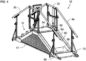
- Figures 1-7 show various full or partial views of a physiotherapeutic stair training system, generally designated 10, constructed and operative according to a particularly preferred embodiment of the present invention.
- system 10 employs a stair structure and lifting mechanism generally similar to that of US Patent No. 9,381,397 to DPE Medical Ltd. (Israel).
- the device has a set 12 of at least three, and in the case shown here four, horizontal tread surfaces, individually referred to as TR0, TR1, TR2 and TR3.
- a drive system 14 is mechanically linked to the set 12 of tread surfaces and configured to displace at least two of the tread surfaces TR1-TR3 vertically so as to adjust a rise height between adjacent of the tread surfaces in such a manner as to form a set of stairs 12 with uniform pitch for a range of different rise heights.
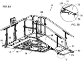
- FIG. 5A A preferred but non-limiting implementation of drive system 14 is best seen in FIG. 5A .
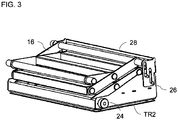
- a scissors mechanism 16 Under each tread surface is a scissors mechanism 16, which allows vertical movement of the tread surface while ensuring that it remains parallel to the floor.
- a linear drive shown here in the form of a screw actuator 18, is deployed in a column 20 beside top tread surface TR3 and deployed to move tread surface TR3 vertically.
- Other types of actuators such as hydraulic or pneumatic actuators, may also be used.
- Two side rails 22 are pivotally linked to top tread surface TR3 so as to be lifted at one end as the top tread surface rises.
- Each of the other tread surfaces has lateral projections 24 ( FIG.
- FIGS. 1 and 4 the scissors mechanisms are hidden by a folding protective skirt 17 to prevent objects or persons from being caught in the mechanisms, the protective skirt having been removed in FIGS. 5A and 6A to reveal the structural details.
- each tread surface (other than TR0) is generally integrally formed with a riser surface 26 to form a step structure.
- Drive system 14 is preferably configured to displace the tread surfaces in a purely vertical motion, such as through the aforementioned scissors mechanisms 16.
- each step also includes a telescopic extension portion 28 which provides an extension to riser surface 26 in the higher raised positions of the system, such as is seen in FIG. 1 .
- a telescopic extension portion allows the system to assume a fully lowered state ( FIG. 2 ) in which a spacing from the floor is less than the maximum rise height of the set of stairs 12 in the fully raised state.
- certain particularly preferred implementations of the present invention provide an adjustable step rise up to in excess of 16 centimeters, and preferably up to at least 18 centimeters, while the tread surfaces in the fully-lowered state are preferably less than 15 centimeters above the underlying surface, and most preferably no more than about 12 centimeters above the underlying surface.
- the system preferably also includes at least one handrail extending alongside the set of stairs 12.
- an adjustable-height handrail 30 is provided on each side of the set of stairs 12, and is complemented by handrail portions 32 extending along the top tread surface, which is here extended to form an upper platform to facilitate turning around between the ascent and descent when required.
- the handrail may additionally or alternatively be adjustable in horizontal position, to allow adjustment of the spacing between the right and left rails.
- Drive system 14 is preferably configured to displace the tread surfaces so as to form the set of stairs 12 with a plurality of rise heights substantially spanning a majority of a range from 0 cm to 18 cm.
- “Substantially spanning” in this context refers to adjustability which provides either continuous adjustment or a plurality of discrete positions which are spaced apart by no more than 2 cm, and more typically in steps of 1 cm or less.
- the system provides adjustment to substantially span the entirety of a range of at least 0-18 cm, thereby facilitating practice of all common step sizes.
- the system preferably assumes a fully flattened (zero step) state, as illustrated in FIG. 2 .
- the plurality of tread surfaces are juxtaposed as a continuous flat surface.
- the present invention makes available an additional form of activity in the form of an adjustable ramp 60 (also referred to herein as a "slope” or “incline”) for assessing and practicing the patient's ability to ascend and/or descend a slope.
- Ramp 60 has a first end 62 hingedly connected to the last tread surface TR3 so as to define a walking surface 64 from first end 62 to a second end 66 of the ramp.
- Walking surface 64 has a variable angle of inclination varying as a function of a vertical position of the last tread surface TR3.
- a support configuration deployed to support second end 66 of ramp 60 over a range of motion such that, in the fully-lowered state of FIG. 2 , second end 66 of ramp 60 is supported above the underlying surface with its walking surface 64 horizontal so that the plurality of tread surfaces TR0, TR1, TR2, TR3 and walking surface 64 together form a continuous horizontal walkway.
- the various components such as scissor mechanisms 16 and riser surfaces 26 dictate a minimum height above the underlying surface at which the "zero" rise flat surface of the steps can be provided. If second end 66 of ramp 60 were to extend to the floor level, this would result in a small residual slope.
- the support configuration of this aspect of the present invention addresses this issue by ensuring that the orientation of walking surface 64 in the zero-rise state is parallel to the underlying surface, thus contributing to an extended horizontal walkway along the length of device 10, preferably of at least 2.5 meters, and typically at least about 3 meters long.
- the support configuration may take a wide range of forms, and may define various different loci of motion of second end 66 as the angle of the ramp varies.
- device 10 is formed with a pair of rails 68, which in the case illustrated here are elements of a device frame extending along the entire length of the device, along which second end 66 slides supported by sliding bearings 70. Sliding bearings may be preferred over rolling bearings due to the relatively large contact area and consequent spreading of load, although roller bearings may also be used.
- a connecting ramp 72 is preferably provided with an upper edge 74 hingedly connected to second end 66 of ramp 60, as best seen in FIG. 5B .
- Connecting ramp 72 terminates at a lower edge 76 adjacent to the underlying surface. "Adjacent" in this context indicates that lower edge 76 is sufficiently close to the underlying surface that a patient's foot cannot get caught beneath it.
- Preferably lower edge 76 is also sufficiently thin that it does not present a significant step to mount the leading edge.
- the leading edge is therefore preferably no more than about 3 centimeters thick, and more preferably no more than about 2 centimeters thick.
- lower edge 76 of connecting ramp 72 is preferably also mounted on bearings, shown here as roller bearings 78, which may roll directly on the underlying surface or, more preferably, on a thin inward-projecting lip 80 from rails 68.
- a second connecting ramp 82 it typically provided at the end of the device opposite to connecting ramp 72 to help patients mount the first step TR0.
- Step TR0 and connecting ramp 82 are typically fixed, static components.
- the linear actuator 18 deployed for raising the device vertically is preferably deployed outside the area of the walkway, as illustrated, and most typically adjacent to a side of the upper platform, corresponding to TR3.
- An elevation sensor or "rise height sensor” 50 ( FIG. 7 , typically implemented as a linear encoder directly measuring the platform height, or a linear or rotary encoder tracking motion of the actuator) gives an indication of the position of the platform, and hence also of the step rise, at any time.
- adjustment of the height of the central platform simultaneously adjusts both the uniform step height and the angle of inclination of the slope, making available two distinct modes of therapeutic activity.
- the output of the elevation sensor also indicates the current angle of inclination of the slope.
- the present invention features a computer system 34 comprising at least one processor 36 and a non-volatile data storage medium 38, typically together with networking components 40 for connection to a wired or wireless network.
- Computer system 34 may be any type of suitable computer, including but not limited to, a general purpose computer running suitable software under a suitable operating system, and a dedicated computer system configured by suitable hardware, software and/or firmware to perform the various functions required.
- computer system 34 may be implemented using a mobile electronics device such as a smartphone operating suitable software and in wireless communication with the various other components of the system.
- Computer system 34 is preferably associated with, and possibly integrated with, one or more user input device 42 and a display 44. In one preferred case, the entire computer system 34 is integrated in a "tablet" configuration with a touch-screen which serves as both the input device and the display, as illustrated schematically in FIG. 1 .
- Control of the up/down motion of drive system 14 may be achieved by pressing directly on up/down buttons on a controller 46 associated with drive system 14. Additionally, or alternatively, control of drive system 14 may be achieved via the user interface of computer system 34.
- Computer system 34 is preferably associated with a sensor set 48 including at least one sensor deployed for measuring a parameter related to physiotherapy performed using device 10. Preferred examples of the sensors, and corresponding modes of operation of the system, are described below.
- the device is provided with at least three sensors for sensing the presence of the patient at specific locations on the device.
- These sensors preferably include a first sensor 52 deployed for sensing the presence of the patient on the first (lowest) step TR0; a second sensor 54 deployed for sensing the presence of the patient on the central platform TR3; and a third sensor 56 deployed for sensing the presence of the patient adjacent to the bottom end of the ramp 60.
- the sensors may advantageously be implemented as pressure sensors built into the surfaces on which the user steps, although any other suitable type of sensors may be used, including but not limited to: optical sensors, proximity sensors, RFID-based sensing arrangements, and image-processing-based detection.
- the deployment of the first, second and third sensors 52, 54 and 56 as described herein provides valuable functionality, as the system can automatically identify and record the type(s) of activity performed during a treatment session. This is illustrated in FIG. 8 .
- the order in which the sensors detect the presence of the patient indicates what combination of stair or slope climbing or descent has been performed, as follows: Case Order Activity A 1-2-1 Ascend stairs; descend stairs B 3-2-3 Ascend slope; descend slope C 1-2-3 Ascend stairs; descend slope D 3-2-1 Ascend slope; descend stairs C or D 1-2-3 or 3-2-1 [Zero elevation] Walking
- the time from leaving one sensor until reaching the next gives a measure of the time taken on that occasion to complete the identified activity.
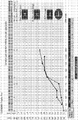
- This information is preferably stored together with the step rise or incline gradient/angle as part of the patient's personal record of treatment and performance (using data storage and recall functionality provided by computer system 34 directly and/or via remote storage accessed via networking components 40), and can then be used to generate a graphic display and/or printed chart or graph of the patient's progress over a course of treatment, facilitating monitoring of the progress of treatment.
- an on-screen display showing a patient's progress is illustrated in FIG. 9 .
- the records of "UP" activities and "DOWN" activities in each therapy session do not necessarily balance. This occurs when a healthcare professional determines that the patient should focus on one or another activity, in which case the height of the device may be reduced or zeroed between ascending and descending, and the minor activity may not be recorded. Additionally, even where data exists for all activities of ascending/descending stairs/slope, it may be preferable to selectively display only part of the data in graphic form at any given time in order to avoid over-cluttering the display. Most preferably, a graphic user interface allows the healthcare professional to select the data to be displayed, for example, displaying plots of progress for ascending stairs and slope without descents, or displaying ascending and descending stairs only. Any and all other combinations may also be used.
- a record of the level-surface walking time between sensors 1 and 3 which records the time taken for the patient to walk a predefined distance on a flat surface, in this case, about 3 meters.
- Walking ability is a further important indicator of the readiness of a patient to return to independent functioning outside a healthcare environment, and many treatment environments lack arrangements for accurately measuring and recording the level-surface walking ability of a patient.
- the combination step-and-incline device of the present invention thus provides significant added value by providing a tool for additionally monitoring and recording the level-surface walking ability of patients.
- the device preferably includes handrails on both sides of the device, which are subdivided into rails 32 of the central platform, rails 30 for the stairs and rails 84 for ramp 60.
- the handrails preferably also extend to or beyond connecting ramps 72 and 82.
- the handrails for the stairs and ramp are preferably hingedly interconnected with supports for the central platform handrails, and are mounted via pin-in-slot engagements, or some other linear-bearing arrangement, to poles near the extremities of device 10, to accommodate changes in the length of handrail between the supports as the elevation is adjusted.
- the handrails are preferably supported by adjustable supports to allow for adjustment for patients of different heights, such as for adults and children.
- a mechanism may also be provided (not shown) to allow adjustment of the horizontal position of the handrails, and thus adjust the span between the handrails.
- the system preferably includes or interfaces with additional components including, but not limited to, control system components, user interface components, networking components and remote computer systems, and/or additional sensors, to provide additional functionality.
- additional components including, but not limited to, control system components, user interface components, networking components and remote computer systems, and/or additional sensors, to provide additional functionality.
Landscapes
- Health & Medical Sciences (AREA)
- General Health & Medical Sciences (AREA)
- Physical Education & Sports Medicine (AREA)
- Orthopedic Medicine & Surgery (AREA)
- Life Sciences & Earth Sciences (AREA)
- Rehabilitation Therapy (AREA)
- Veterinary Medicine (AREA)
- Public Health (AREA)
- Animal Behavior & Ethology (AREA)
- Vascular Medicine (AREA)
- Pathology (AREA)
- Epidemiology (AREA)
- Cardiology (AREA)
- Physiology (AREA)
- Dentistry (AREA)
- Oral & Maxillofacial Surgery (AREA)
- Physics & Mathematics (AREA)
- Biophysics (AREA)
- Pain & Pain Management (AREA)
- Engineering & Computer Science (AREA)
- Biomedical Technology (AREA)
- Heart & Thoracic Surgery (AREA)
- Medical Informatics (AREA)
- Molecular Biology (AREA)
- Surgery (AREA)
- Rehabilitation Tools (AREA)
Claims (9)
- System (10) zur Bereitstellung auf einer darunter liegenden Oberfläche, wobei das System umfasst:(a) einen Satz (12) von mindestens drei horizontalen Trittflächen (TRO, TR1, TR2, TR3), einschließlich einer ersten Trittfläche (TR0) und einer letzten Trittfläche (TR3); und(b) ein Antriebssystem (14), das mechanisch mit dem Satz (12) von Trittflächen verbunden und konfiguriert ist, mindestens zwei derTrittflächen vertikal zu verschieben, um eine Anstiegshöhe zwischen benachbarten Trittflächen derart anzupassen, dass ein Satz Stufen mit gleichmäßiger Steigung für verschiedene Höhen gebildet wird,wobei das Antriebssystem (14) konfiguriert ist, die Trittflächen in einen vollständig abgesenkten Zustand zu versetzen, in dem der Satz von Trittfflächen als durchgehende flache Oberfläche nebeneinander angeordnet ist;
dadurch gekennzeichnet, dass das System ferner umfasst:(c) eine Rampe (60) mit einem ersten Ende (62), das mit der letzten Trittfläche (TR3) gelenkig verbunden ist, um eine Lauffläche (64) von dem ersten Ende (62) zu einem zweiten Ende (66) der Rampe zu definieren; wobei die Lauftfläche einen variablen Neigungswinkel aufweist, der als Funktion einer vertikalen Position der letzten Trittfläche variiert; und(d) eine Stützstruktur (68, 70), die eingesetzt wird, um das zweite Ende (66) der Rampe über einen Bewegungsbereich derart zu stützen, dass in dem vollständig abgesenkten Zustand das zweite Ende der Rampe über der darunter liegenden Oberfläche abgestützt wird, wobei die Lauffläche (64) horizontal ist und wobei die mehreren Trittflächen (TRO, TR1, TR2, TR3) und die Lauffläche (64) zusammen einen durchgehenden horizontalen Laufsteg bilden. - System (10) nach Anspruch 1, wobei das Antriebssystem (14) einen Linearantrieb (18) umfasst, der zum vertikalen Anheben der letzten Trittfläche (TR3) eingesetzt wird, wobei der Linearantrieb außerhalb eines Bereichs des Laufstegs eingesetzt ist.
- System (10) nach Anspruch 1, wobei sich der durchgehende horizontale Laufsteg in einer ersten Höhe über der darunter liegenden Oberfläche befindet, wobei das System ferner eine Verbindungsrampe (72) mit einer Oberkante (74) umfasst, die mit dem zweiten Ende (66) der Rampe gelenkig verbunden ist, wobei die Verbindungsrampe (72) an einer Unterkante (76) neben der darunter liegenden Oberfläche endet.
- System (10) nach Anspruch 1, wobei das Antriebssystem (14) konfiguriert ist, die Trittflächen (TRO, TR1, TR2, TR3) zu verschieben, um den Satz Treppen mit einer Vielzahl von Steighöhen zu bilden, die sich im Wesentlichen über eine Mehrheit in einem Bereich von 0 cm bis 18 cm erstrecken.
- System (10) nach Anspruch 1, wobei das Antriebssystem (14) konfiguriert ist, die Trittflächen (TRO, TR1, TR2, TR3) in einer rein vertikalen Bewegung zu verschieben, und wobei mehreren der Trittflächen jeweils eine vertikale Steigfläche (26) zugeordnet ist.
- System (10) nach Anspruch 1, ferner umfassend:(a) einen Satz (48) von Sensoren, der Folgendes beinhaltet:(i) einen ersten Sensor (52), der eingesetzt wird, um die Anwesenheit eines Patienten auf der ersten Trittfläche (TR0) zu erfassen,(ii) einen zweiten Sensor (54), der eingesetzt wird, um die Anwesenheit einer Person auf der letzten Trittfläche (TR3) zu erfassen, und(iii) einen dritten Sensor (56), der eingesetzt wird, um die Anwesenheit einer Person auf der Rampe (60) in einem Bereich neben dem zweiten Ende (66) zu erfassen; und(b) ein Computersystem (34), das mindestens einen Prozessor (36) und ein nichtflüchtiges Speichermedium (38) umfasst, wobei das Computersystem mit dem Satz (48) von Sensoren in Verbindung steht, wobei der Computer konfiguriert ist, einen Datensatz einer Patientenaktivität zu erzeugen, wobei die Patientenaktivität zumindest teilweise aus einer Folge von Ausgaben des ersten, zweiten und dritten Sensors (52, 54, 56) bestimmt wird.
- System (10) nach Anspruch 6, wobei der Satz von Sensoren ferner einen Anstiegshöhensensor (50) umfasst, der eingesetzt wird, um eine Ausgabe zu erzeugen, die eine aktuelle Anstiegshöhe des Satzes (12) von Stufen und eine aktuelle Neigung der Rampe (50) anzeigt, wobei das Computersystem (34) konfiguriert ist, mindestens zwei der Folgenden auszuführen:(a) beim Erfassen eines Patienten an dem ersten Sensor (52), gefolgt von dem zweiten Sensor (54) bei einer Anstiegshöhe ungleich Null, Identifizieren einer Zeit vom Erfassen des ersten Sensors bis zum Erfassen des zweiten Sensors als eine Zeit, die für das Steigen der Stufen bei der aktuell erfassten Anstiegshöhe benötigt wird;(b) beim Erfassen eines Patienten an dem dritten Sensor (56), gefolgt von dem zweiten Sensor (54) bei einer Anstiegshöhe ungleich Null, Identifizieren einer Zeit vom Erfassen des dritten Sensors bis zum Erfassen des zweiten Sensors als eine Zeit, die für das Steigen der Stufen bei der aktuell erfassten Anstiegshöhe benötigt wird;(c) beim Erfassen einer Anstiegshöhe gleich Null, Identifizieren einer Zeit vom Erfassen eines Patienten an dem ersten Sensor (52) bis zum Erfassen eines Patienten an dem dritten Sensor (56) oder umgekehrt als eine Zeit, die benötigt wird, um eine vordefinierte horizontale Strecke zu gehen.
- System (10) nach Anspruch 1,
dadurch gekennzeichnet, dass das System ferner umfasst:(d) einen Satz (48) von Sensoren, der Folgendes beinhaltet:(i) einen ersten Sensor (52), der eingesetzt wird, um die Anwesenheit eines Patienten auf der ersten Trittfläche (TR0) zu erfassen,(ii) einen zweiten Sensor (54), der eingesetzt wird, um die Anwesenheit einer Person auf der letzten Trittfläche (TR3) zu erfassen, und(iii) einen dritten Sensor (56), der eingesetzt wird, um die Anwesenheit einer Person auf der Rampe (60) in einem Bereich neben dem zweiten Ende (66) zu erfassen; und(e) ein Computersystem (34), das mindestens einen Prozessor (36) und ein nichtflüchtiges Speichermedium (38) umfasst, wobei das Computersystem mit dem Satz von Sensoren in Verbindung steht, wobei der Computer konfiguriert ist, um einen Datensatz einer Patientenaktivität zu erzeugen wobei die Patientenaktivität zumindest teilweise aus einer Folge von Ausgaben des ersten, zweiten und dritten Sensors (52, 54, 56) bestimmt wird. - System (10) nach Anspruch 8, wobei der Satz (48) von Sensoren ferner einen Anstiegshöhensensor (50) umfasst, der eingesetzt wird, um eine Ausgabe zu erzeugen, die eine aktuelle Anstiegshöhe des Satzes (12) von Stufen und eine aktuelle Neigung der Rampe (50) anzeigt, wobei das Computersystem (34) konfiguriert ist, mindestens zwei der Folgenden auszuführen:(a) beim Erfassen eines Patienten an dem ersten Sensor (52), gefolgt von dem zweiten Sensor (54) bei einer Anstiegshöhe ungleich Null, Identifizieren einer Zeit vom Erfassen des ersten Sensors bis zum Erfassen des zweiten Sensors als eine Zeit, die für das Steigen der Stufen bei der aktuell erfassten Anstiegshöhe benötigt wird;(b) beim Erfassen eines Patienten an dem dritten Sensor (56), gefolgt von dem zweiten Sensor (54) bei einer Anstiegshöhe ungleich Null, Identifizieren einer Zeit vom Erfassen des dritten Sensors bis zum Erfassen des zweiten Sensors als eine Zeit, die für das Steigen der Stufen bei der aktuell erfassten Anstiegshöhe benötigt wird;(c) beim Erfassen einer Anstiegshöhe gleich Null, Identifizieren einer Zeit vom Erfassen eines Patienten an dem ersten Sensor (52) bis zum Erfassen eines Patienten an dem dritten Sensor (56) oder umgekehrt als eine Zeit, die benötigt wird, um eine vordefinierte horizontale Strecke zu gehen.
Priority Applications (1)
| Application Number | Priority Date | Filing Date | Title |
|---|---|---|---|
| PL17869513T PL3538229T3 (pl) | 2016-11-13 | 2017-11-12 | Fizjoterapeutyczny system schodów i pochylni |
Applications Claiming Priority (2)
| Application Number | Priority Date | Filing Date | Title |
|---|---|---|---|
| US15/350,055 US9895576B1 (en) | 2016-11-13 | 2016-11-13 | Physiotherapeutic stair and incline system |
| PCT/IL2017/051228 WO2018087765A1 (en) | 2016-11-13 | 2017-11-12 | Physiotherapeutic stair & incline system |
Publications (3)
| Publication Number | Publication Date |
|---|---|
| EP3538229A1 EP3538229A1 (de) | 2019-09-18 |
| EP3538229A4 EP3538229A4 (de) | 2019-12-04 |
| EP3538229B1 true EP3538229B1 (de) | 2021-06-16 |
Family
ID=61188579
Family Applications (1)
| Application Number | Title | Priority Date | Filing Date |
|---|---|---|---|
| EP17869513.6A Active EP3538229B1 (de) | 2016-11-13 | 2017-11-12 | Physiotherapeutisches stufen- und neigungssystem |
Country Status (6)
| Country | Link |
|---|---|
| US (1) | US9895576B1 (de) |
| EP (1) | EP3538229B1 (de) |
| JP (1) | JP2019535381A (de) |
| PL (1) | PL3538229T3 (de) |
| RU (1) | RU2755582C1 (de) |
| WO (1) | WO2018087765A1 (de) |
Cited By (1)
| Publication number | Priority date | Publication date | Assignee | Title |
|---|---|---|---|---|
| WO2024242585A1 (ru) * | 2023-05-19 | 2024-11-28 | Валерий Филиппович ИВАНОВ | Устройство для оценки функционального состояния сердца посредством пульсометра |
Families Citing this family (18)
| Publication number | Priority date | Publication date | Assignee | Title |
|---|---|---|---|---|
| US10920492B2 (en) * | 2015-10-07 | 2021-02-16 | Intex Marketing Ltd. | Ladder with safety features |
| US10744361B2 (en) * | 2017-03-31 | 2020-08-18 | Zelda Duval | Collapsible exercise board and equipment |
| USD879889S1 (en) | 2017-05-08 | 2020-03-31 | ProStairs Fitness, LLC | Exercise apparatus |
| US10792527B1 (en) * | 2017-05-08 | 2020-10-06 | ProStairs Fitness, LLC | Exercise apparatus having a stair and slide assembly |
| US11007944B1 (en) * | 2017-11-27 | 2021-05-18 | Hwh Corporation | Automatic railing for a retractable stairway |
| CN111870878B (zh) * | 2018-06-21 | 2021-07-27 | 南京溧水高新产业股权投资有限公司 | 基于训练高效且适应多种盲人行走的盲人直线行走装置及使用方法 |
| CN109009890B (zh) * | 2018-08-14 | 2020-09-11 | 杭州富阳和翔模具有限公司 | 一种骨科患者助行训练设备 |
| CN109264545B (zh) * | 2018-11-06 | 2020-04-14 | 安阳工学院 | 一种电动的调整楼梯及其使用方法 |
| US20200270107A1 (en) * | 2019-02-26 | 2020-08-27 | Hhi Corporation | Adjustable aircraft maintenance stand |
| DE202019001159U1 (de) * | 2019-03-12 | 2019-04-04 | Blue Star Gmbh | Treppensystemvorrichtung |
| US11813216B1 (en) * | 2019-08-08 | 2023-11-14 | Richard Joshua Riess | Multi-therapeutic patient lift and parallel bars system |
| CN110947160A (zh) * | 2019-12-26 | 2020-04-03 | 武汉尚诚源健康科技有限公司 | 一种台阶高度可调的训练阶梯 |
| CN112138335A (zh) * | 2020-08-06 | 2020-12-29 | 苏州工业园区服务外包职业学院 | 辅助直立装置 |
| CN114404892B (zh) * | 2022-01-25 | 2022-11-04 | 信阳市第四人民医院 | 一种多功能的妇产科用辅助装置 |
| CN115404937B (zh) * | 2022-08-31 | 2023-05-30 | 华能伊敏煤电有限责任公司 | 一种具有储物功能的防滑斜梯 |
| CN116889710A (zh) * | 2023-06-01 | 2023-10-17 | 黄山金富医疗器械有限公司 | 一种步态训练双梯 |
| KR102907292B1 (ko) * | 2024-02-16 | 2026-01-05 | (주)광원메디텍 | 스마트형 복합 보행 훈련장치 |
| CN119607511B (zh) * | 2025-02-14 | 2025-05-16 | 山东泽普医疗科技有限公司 | 一种升降平衡训练台及控制系统 |
Family Cites Families (21)
| Publication number | Priority date | Publication date | Assignee | Title |
|---|---|---|---|---|
| US3497215A (en) * | 1967-04-03 | 1970-02-24 | Univ Johns Hopkins | Exercise escalator |
| US5769759A (en) * | 1997-01-30 | 1998-06-23 | Alter; Joseph W. | Stair climbing apparatus |
| US5901813A (en) * | 1997-05-12 | 1999-05-11 | Orgal; Daniel | Physiotherapeutic device |
| US6601677B1 (en) * | 1997-07-14 | 2003-08-05 | Vertical Mobility, L.L.C. | Convertible lift mechanism having a number of retractable stairs with a lift platform positioned thereunder |
| US6217484B1 (en) * | 1999-01-05 | 2001-04-17 | Edward J. Harshman | Rehabilitation apparatus |
| US6238320B1 (en) * | 1999-06-09 | 2001-05-29 | Dennis Flanagan | Modular suspended floor and step arrangement |
| JP2002017890A (ja) * | 2000-07-04 | 2002-01-22 | Tokuyuki Iguchi | 歩行用運動器具 |
| US6609478B2 (en) * | 2000-12-01 | 2003-08-26 | Juanquin Del Valle | Treadmill system |
| US7383600B2 (en) * | 2005-04-05 | 2008-06-10 | Carrigan Stephen A | Convertible dock ramp |
| US20090124464A1 (en) * | 2006-12-03 | 2009-05-14 | Kastelic Edward P | Multi-Configurable Exercise Device |
| RU2393837C2 (ru) * | 2008-10-08 | 2010-07-10 | Юрий Георгиевич Жуковский | Устройство для физиотерапии детского церебрального паралича |
| WO2010048348A2 (en) * | 2008-10-21 | 2010-04-29 | Rakesh Patel | Assisted stair training machine and methods of using |
| CN201299751Y (zh) * | 2008-11-03 | 2009-09-02 | 李振华 | 一种移动式肢体康复训练器 |
| US8807283B2 (en) * | 2009-01-09 | 2014-08-19 | Dennis Shell | Lift apparatus |
| WO2012057595A1 (es) | 2010-10-26 | 2012-05-03 | Instituto Tecnológico y de Estudios Superiores de Monterrey | Sistema de escalera y rampa variables para rehabilitación de extremidades inferiores |
| CN103043220B (zh) * | 2011-10-13 | 2015-07-01 | 王力丰 | 航空母舰舰载机起降系统及其起降方法 |
| DE102012205162A1 (de) * | 2012-03-29 | 2013-10-02 | Siemens Aktiengesellschaft | Beobachtung und/oder Bedienung eines Sport- und/oder Rehabilitationsgerätes |
| RU2513418C1 (ru) * | 2012-12-19 | 2014-04-20 | Ирина Львовна Солонец | Способ комплексной реабилитации больных в раннем восстановительном периоде церебрального инсульта |
| US9381397B2 (en) * | 2013-11-20 | 2016-07-05 | DPE Medical Ltd | Computer-aided physiotherapeutic stair and gait system |
| CA2844895C (en) * | 2014-03-05 | 2020-12-01 | Ottawa Hospital Research Institute | Adjustable staircase |
| CN205460722U (zh) * | 2016-04-08 | 2016-08-17 | 王俊虎 | 一种康复平行杠 |
-
2016
- 2016-11-13 US US15/350,055 patent/US9895576B1/en active Active
-
2017
- 2017-11-12 RU RU2019114923A patent/RU2755582C1/ru active
- 2017-11-12 WO PCT/IL2017/051228 patent/WO2018087765A1/en not_active Ceased
- 2017-11-12 PL PL17869513T patent/PL3538229T3/pl unknown
- 2017-11-12 JP JP2019524034A patent/JP2019535381A/ja active Pending
- 2017-11-12 EP EP17869513.6A patent/EP3538229B1/de active Active
Non-Patent Citations (1)
| Title |
|---|
| None * |
Cited By (1)
| Publication number | Priority date | Publication date | Assignee | Title |
|---|---|---|---|---|
| WO2024242585A1 (ru) * | 2023-05-19 | 2024-11-28 | Валерий Филиппович ИВАНОВ | Устройство для оценки функционального состояния сердца посредством пульсометра |
Also Published As
| Publication number | Publication date |
|---|---|
| JP2019535381A (ja) | 2019-12-12 |
| US9895576B1 (en) | 2018-02-20 |
| EP3538229A4 (de) | 2019-12-04 |
| PL3538229T3 (pl) | 2022-02-14 |
| RU2755582C1 (ru) | 2021-09-17 |
| WO2018087765A1 (en) | 2018-05-17 |
| EP3538229A1 (de) | 2019-09-18 |
Similar Documents
| Publication | Publication Date | Title |
|---|---|---|
| US9895576B1 (en) | Physiotherapeutic stair and incline system | |
| EP3071303B1 (de) | Computergestützte physiotherapeutische treppe und gangsystem | |
| US20230356024A1 (en) | Seated treadmill and method of use | |
| EP2583652B1 (de) | Intelligentes krankenhausbett | |
| CA2844895C (en) | Adjustable staircase | |
| US11547898B2 (en) | Seated treadmill and method of use | |
| EP3888543B1 (de) | Patientenkörperüberwachung mithilfe von radar | |
| EP3653110B1 (de) | System zur bestimmung eines druckgeschwürscores und änderung eines behandlungsplans basierend auf dem druckgeschwürscore | |
| JP2003047635A (ja) | 歩行訓練機 | |
| US12005012B2 (en) | Patient bed having exercise therapy apparatus | |
| CN104398347B (zh) | 一种新型轮椅式电动步行训练装置及控制方法 | |
| US10532247B2 (en) | Exercise device | |
| US20130139318A1 (en) | Bed with weight bearing control system | |
| CN218106681U (zh) | 一种重心调整及视觉反馈训练装置 | |
| KR20230125453A (ko) | 환자의 자세를 추정하여 사이드 레일을 제어하는 의료용 침대 | |
| KR102137084B1 (ko) | 계단형 트레드밀 헬스케어 시스템 | |
| KR101015387B1 (ko) | 욕창방지를 위한 사용자의 신체조건에 따라 자세변환주기가 제어되는 전동침대 플랫폼 | |
| CN205699165U (zh) | 原地踏步装置 | |
| WO2008052220A2 (en) | Ambulatory hospital bed | |
| KR20180002984A (ko) | 요추기립근을 강화할 수 있는 재활훈련기기 | |
| CN221304272U (zh) | 一种术后康复锻炼可视化智能康复仪 | |
| CN214434856U (zh) | 一种影像科用人体转移平台 | |
| JPH02261477A (ja) | ステップ高可変歩行練習用階段 | |
| KR102912906B1 (ko) | 변형 가능한 매트리스를 포함하는 병원용 침대 시스템 | |
| TWI754314B (zh) | 起身輔助裝置及其方法 |
Legal Events
| Date | Code | Title | Description |
|---|---|---|---|
| STAA | Information on the status of an ep patent application or granted ep patent |
Free format text: STATUS: THE INTERNATIONAL PUBLICATION HAS BEEN MADE |
|
| PUAI | Public reference made under article 153(3) epc to a published international application that has entered the european phase |
Free format text: ORIGINAL CODE: 0009012 |
|
| STAA | Information on the status of an ep patent application or granted ep patent |
Free format text: STATUS: REQUEST FOR EXAMINATION WAS MADE |
|
| 17P | Request for examination filed |
Effective date: 20190612 |
|
| AK | Designated contracting states |
Kind code of ref document: A1 Designated state(s): AL AT BE BG CH CY CZ DE DK EE ES FI FR GB GR HR HU IE IS IT LI LT LU LV MC MK MT NL NO PL PT RO RS SE SI SK SM TR |
|
| AX | Request for extension of the european patent |
Extension state: BA ME |
|
| A4 | Supplementary search report drawn up and despatched |
Effective date: 20191030 |
|
| RIC1 | Information provided on ipc code assigned before grant |
Ipc: A63B 24/00 20060101ALI20191025BHEP Ipc: A63B 23/04 20060101AFI20191025BHEP |
|
| DAV | Request for validation of the european patent (deleted) | ||
| DAX | Request for extension of the european patent (deleted) | ||
| GRAP | Despatch of communication of intention to grant a patent |
Free format text: ORIGINAL CODE: EPIDOSNIGR1 |
|
| STAA | Information on the status of an ep patent application or granted ep patent |
Free format text: STATUS: GRANT OF PATENT IS INTENDED |
|
| INTG | Intention to grant announced |
Effective date: 20210112 |
|
| GRAS | Grant fee paid |
Free format text: ORIGINAL CODE: EPIDOSNIGR3 |
|
| GRAA | (expected) grant |
Free format text: ORIGINAL CODE: 0009210 |
|
| STAA | Information on the status of an ep patent application or granted ep patent |
Free format text: STATUS: THE PATENT HAS BEEN GRANTED |
|
| AK | Designated contracting states |
Kind code of ref document: B1 Designated state(s): AL AT BE BG CH CY CZ DE DK EE ES FI FR GB GR HR HU IE IS IT LI LT LU LV MC MK MT NL NO PL PT RO RS SE SI SK SM TR |
|
| REG | Reference to a national code |
Ref country code: GB Ref legal event code: FG4D |
|
| REG | Reference to a national code |
Ref country code: CH Ref legal event code: EP |
|
| REG | Reference to a national code |
Ref country code: DE Ref legal event code: R096 Ref document number: 602017040569 Country of ref document: DE |
|
| REG | Reference to a national code |
Ref country code: AT Ref legal event code: REF Ref document number: 1401835 Country of ref document: AT Kind code of ref document: T Effective date: 20210715 |
|
| REG | Reference to a national code |
Ref country code: IE Ref legal event code: FG4D |
|
| REG | Reference to a national code |
Ref country code: LT Ref legal event code: MG9D |
|
| PG25 | Lapsed in a contracting state [announced via postgrant information from national office to epo] |
Ref country code: FI Free format text: LAPSE BECAUSE OF FAILURE TO SUBMIT A TRANSLATION OF THE DESCRIPTION OR TO PAY THE FEE WITHIN THE PRESCRIBED TIME-LIMIT Effective date: 20210616 Ref country code: LT Free format text: LAPSE BECAUSE OF FAILURE TO SUBMIT A TRANSLATION OF THE DESCRIPTION OR TO PAY THE FEE WITHIN THE PRESCRIBED TIME-LIMIT Effective date: 20210616 Ref country code: BG Free format text: LAPSE BECAUSE OF FAILURE TO SUBMIT A TRANSLATION OF THE DESCRIPTION OR TO PAY THE FEE WITHIN THE PRESCRIBED TIME-LIMIT Effective date: 20210916 Ref country code: HR Free format text: LAPSE BECAUSE OF FAILURE TO SUBMIT A TRANSLATION OF THE DESCRIPTION OR TO PAY THE FEE WITHIN THE PRESCRIBED TIME-LIMIT Effective date: 20210616 |
|
| REG | Reference to a national code |
Ref country code: AT Ref legal event code: MK05 Ref document number: 1401835 Country of ref document: AT Kind code of ref document: T Effective date: 20210616 |
|
| REG | Reference to a national code |
Ref country code: NL Ref legal event code: MP Effective date: 20210616 |
|
| PG25 | Lapsed in a contracting state [announced via postgrant information from national office to epo] |
Ref country code: GR Free format text: LAPSE BECAUSE OF FAILURE TO SUBMIT A TRANSLATION OF THE DESCRIPTION OR TO PAY THE FEE WITHIN THE PRESCRIBED TIME-LIMIT Effective date: 20210917 Ref country code: SE Free format text: LAPSE BECAUSE OF FAILURE TO SUBMIT A TRANSLATION OF THE DESCRIPTION OR TO PAY THE FEE WITHIN THE PRESCRIBED TIME-LIMIT Effective date: 20210616 Ref country code: RS Free format text: LAPSE BECAUSE OF FAILURE TO SUBMIT A TRANSLATION OF THE DESCRIPTION OR TO PAY THE FEE WITHIN THE PRESCRIBED TIME-LIMIT Effective date: 20210616 Ref country code: LV Free format text: LAPSE BECAUSE OF FAILURE TO SUBMIT A TRANSLATION OF THE DESCRIPTION OR TO PAY THE FEE WITHIN THE PRESCRIBED TIME-LIMIT Effective date: 20210616 Ref country code: NO Free format text: LAPSE BECAUSE OF FAILURE TO SUBMIT A TRANSLATION OF THE DESCRIPTION OR TO PAY THE FEE WITHIN THE PRESCRIBED TIME-LIMIT Effective date: 20210916 |
|
| PG25 | Lapsed in a contracting state [announced via postgrant information from national office to epo] |
Ref country code: EE Free format text: LAPSE BECAUSE OF FAILURE TO SUBMIT A TRANSLATION OF THE DESCRIPTION OR TO PAY THE FEE WITHIN THE PRESCRIBED TIME-LIMIT Effective date: 20210616 Ref country code: ES Free format text: LAPSE BECAUSE OF FAILURE TO SUBMIT A TRANSLATION OF THE DESCRIPTION OR TO PAY THE FEE WITHIN THE PRESCRIBED TIME-LIMIT Effective date: 20210616 Ref country code: SM Free format text: LAPSE BECAUSE OF FAILURE TO SUBMIT A TRANSLATION OF THE DESCRIPTION OR TO PAY THE FEE WITHIN THE PRESCRIBED TIME-LIMIT Effective date: 20210616 Ref country code: SK Free format text: LAPSE BECAUSE OF FAILURE TO SUBMIT A TRANSLATION OF THE DESCRIPTION OR TO PAY THE FEE WITHIN THE PRESCRIBED TIME-LIMIT Effective date: 20210616 Ref country code: PT Free format text: LAPSE BECAUSE OF FAILURE TO SUBMIT A TRANSLATION OF THE DESCRIPTION OR TO PAY THE FEE WITHIN THE PRESCRIBED TIME-LIMIT Effective date: 20211018 Ref country code: RO Free format text: LAPSE BECAUSE OF FAILURE TO SUBMIT A TRANSLATION OF THE DESCRIPTION OR TO PAY THE FEE WITHIN THE PRESCRIBED TIME-LIMIT Effective date: 20210616 Ref country code: NL Free format text: LAPSE BECAUSE OF FAILURE TO SUBMIT A TRANSLATION OF THE DESCRIPTION OR TO PAY THE FEE WITHIN THE PRESCRIBED TIME-LIMIT Effective date: 20210616 Ref country code: CZ Free format text: LAPSE BECAUSE OF FAILURE TO SUBMIT A TRANSLATION OF THE DESCRIPTION OR TO PAY THE FEE WITHIN THE PRESCRIBED TIME-LIMIT Effective date: 20210616 Ref country code: AT Free format text: LAPSE BECAUSE OF FAILURE TO SUBMIT A TRANSLATION OF THE DESCRIPTION OR TO PAY THE FEE WITHIN THE PRESCRIBED TIME-LIMIT Effective date: 20210616 |
|
| PGFP | Annual fee paid to national office [announced via postgrant information from national office to epo] |
Ref country code: IE Payment date: 20211129 Year of fee payment: 5 Ref country code: GB Payment date: 20211129 Year of fee payment: 5 |
|
| REG | Reference to a national code |
Ref country code: DE Ref legal event code: R097 Ref document number: 602017040569 Country of ref document: DE |
|
| PLBE | No opposition filed within time limit |
Free format text: ORIGINAL CODE: 0009261 |
|
| STAA | Information on the status of an ep patent application or granted ep patent |
Free format text: STATUS: NO OPPOSITION FILED WITHIN TIME LIMIT |
|
| PG25 | Lapsed in a contracting state [announced via postgrant information from national office to epo] |
Ref country code: DK Free format text: LAPSE BECAUSE OF FAILURE TO SUBMIT A TRANSLATION OF THE DESCRIPTION OR TO PAY THE FEE WITHIN THE PRESCRIBED TIME-LIMIT Effective date: 20210616 |
|
| 26N | No opposition filed |
Effective date: 20220317 |
|
| PG25 | Lapsed in a contracting state [announced via postgrant information from national office to epo] |
Ref country code: AL Free format text: LAPSE BECAUSE OF FAILURE TO SUBMIT A TRANSLATION OF THE DESCRIPTION OR TO PAY THE FEE WITHIN THE PRESCRIBED TIME-LIMIT Effective date: 20210616 |
|
| PG25 | Lapsed in a contracting state [announced via postgrant information from national office to epo] |
Ref country code: MC Free format text: LAPSE BECAUSE OF FAILURE TO SUBMIT A TRANSLATION OF THE DESCRIPTION OR TO PAY THE FEE WITHIN THE PRESCRIBED TIME-LIMIT Effective date: 20210616 |
|
| PG25 | Lapsed in a contracting state [announced via postgrant information from national office to epo] |
Ref country code: LU Free format text: LAPSE BECAUSE OF NON-PAYMENT OF DUE FEES Effective date: 20211112 Ref country code: IT Free format text: LAPSE BECAUSE OF FAILURE TO SUBMIT A TRANSLATION OF THE DESCRIPTION OR TO PAY THE FEE WITHIN THE PRESCRIBED TIME-LIMIT Effective date: 20210616 Ref country code: BE Free format text: LAPSE BECAUSE OF NON-PAYMENT OF DUE FEES Effective date: 20211130 |
|
| REG | Reference to a national code |
Ref country code: BE Ref legal event code: MM Effective date: 20211130 |
|
| PG25 | Lapsed in a contracting state [announced via postgrant information from national office to epo] |
Ref country code: CY Free format text: LAPSE BECAUSE OF FAILURE TO SUBMIT A TRANSLATION OF THE DESCRIPTION OR TO PAY THE FEE WITHIN THE PRESCRIBED TIME-LIMIT Effective date: 20210616 |
|
| GBPC | Gb: european patent ceased through non-payment of renewal fee |
Effective date: 20221112 |
|
| PG25 | Lapsed in a contracting state [announced via postgrant information from national office to epo] |
Ref country code: HU Free format text: LAPSE BECAUSE OF FAILURE TO SUBMIT A TRANSLATION OF THE DESCRIPTION OR TO PAY THE FEE WITHIN THE PRESCRIBED TIME-LIMIT; INVALID AB INITIO Effective date: 20171112 |
|
| PG25 | Lapsed in a contracting state [announced via postgrant information from national office to epo] |
Ref country code: IE Free format text: LAPSE BECAUSE OF NON-PAYMENT OF DUE FEES Effective date: 20221112 Ref country code: GB Free format text: LAPSE BECAUSE OF NON-PAYMENT OF DUE FEES Effective date: 20221112 |
|
| PG25 | Lapsed in a contracting state [announced via postgrant information from national office to epo] |
Ref country code: MK Free format text: LAPSE BECAUSE OF FAILURE TO SUBMIT A TRANSLATION OF THE DESCRIPTION OR TO PAY THE FEE WITHIN THE PRESCRIBED TIME-LIMIT Effective date: 20210616 |
|
| PG25 | Lapsed in a contracting state [announced via postgrant information from national office to epo] |
Ref country code: MT Free format text: LAPSE BECAUSE OF FAILURE TO SUBMIT A TRANSLATION OF THE DESCRIPTION OR TO PAY THE FEE WITHIN THE PRESCRIBED TIME-LIMIT Effective date: 20210616 |
|
| REG | Reference to a national code |
Ref country code: CH Ref legal event code: U11 Free format text: ST27 STATUS EVENT CODE: U-0-0-U10-U11 (AS PROVIDED BY THE NATIONAL OFFICE) Effective date: 20251201 |
|
| PG25 | Lapsed in a contracting state [announced via postgrant information from national office to epo] |
Ref country code: TR Free format text: LAPSE BECAUSE OF FAILURE TO SUBMIT A TRANSLATION OF THE DESCRIPTION OR TO PAY THE FEE WITHIN THE PRESCRIBED TIME-LIMIT Effective date: 20210616 |
|
| PGFP | Annual fee paid to national office [announced via postgrant information from national office to epo] |
Ref country code: DE Payment date: 20251118 Year of fee payment: 9 |
|
| PGFP | Annual fee paid to national office [announced via postgrant information from national office to epo] |
Ref country code: FR Payment date: 20251117 Year of fee payment: 9 |
|
| PGFP | Annual fee paid to national office [announced via postgrant information from national office to epo] |
Ref country code: CH Payment date: 20251201 Year of fee payment: 9 |
|
| PGFP | Annual fee paid to national office [announced via postgrant information from national office to epo] |
Ref country code: PL Payment date: 20251104 Year of fee payment: 9 |