EP3538050B1 - Devices and methods for reducing the symptoms of maladies of the vestibular system - Google Patents
Devices and methods for reducing the symptoms of maladies of the vestibular system Download PDFInfo
- Publication number
- EP3538050B1 EP3538050B1 EP17868920.4A EP17868920A EP3538050B1 EP 3538050 B1 EP3538050 B1 EP 3538050B1 EP 17868920 A EP17868920 A EP 17868920A EP 3538050 B1 EP3538050 B1 EP 3538050B1
- Authority
- EP
- European Patent Office
- Prior art keywords
- vestibular
- signals
- magnet
- bone conduction
- conduction transducer
- Prior art date
- Legal status (The legal status is an assumption and is not a legal conclusion. Google has not performed a legal analysis and makes no representation as to the accuracy of the status listed.)
- Active
Links
- 230000001720 vestibular Effects 0.000 title claims description 121
- 208000024891 symptom Diseases 0.000 title claims description 28
- 238000000034 method Methods 0.000 title description 19
- 201000003152 motion sickness Diseases 0.000 claims description 30
- 210000003128 head Anatomy 0.000 claims description 19
- 210000000988 bone and bone Anatomy 0.000 claims description 16
- 230000033001 locomotion Effects 0.000 claims description 13
- 239000000463 material Substances 0.000 claims description 9
- 230000000873 masking effect Effects 0.000 claims description 8
- 208000012886 Vertigo Diseases 0.000 claims description 7
- 208000009205 Tinnitus Diseases 0.000 claims description 6
- 231100000886 tinnitus Toxicity 0.000 claims description 6
- 231100000889 vertigo Toxicity 0.000 claims description 6
- 210000004209 hair Anatomy 0.000 claims description 5
- 210000003780 hair follicle Anatomy 0.000 claims description 5
- 230000002842 otolith Effects 0.000 claims description 5
- 210000001265 otolithic membrane Anatomy 0.000 claims description 5
- 230000001133 acceleration Effects 0.000 claims description 4
- 210000003060 endolymph Anatomy 0.000 claims description 4
- 239000011521 glass Substances 0.000 claims description 4
- 210000003491 skin Anatomy 0.000 claims description 4
- 206010025482 malaise Diseases 0.000 claims description 3
- 208000002173 dizziness Diseases 0.000 claims description 2
- 230000004044 response Effects 0.000 claims description 2
- 230000010355 oscillation Effects 0.000 claims 1
- 238000012360 testing method Methods 0.000 description 44
- 210000004556 brain Anatomy 0.000 description 9
- 230000008569 process Effects 0.000 description 7
- 210000003027 ear inner Anatomy 0.000 description 5
- 210000001508 eye Anatomy 0.000 description 5
- 238000005259 measurement Methods 0.000 description 5
- 206010029864 nystagmus Diseases 0.000 description 5
- 230000001953 sensory effect Effects 0.000 description 5
- 238000001514 detection method Methods 0.000 description 4
- 230000000694 effects Effects 0.000 description 4
- 238000002474 experimental method Methods 0.000 description 4
- 239000004593 Epoxy Substances 0.000 description 3
- 206010028813 Nausea Diseases 0.000 description 3
- 239000000853 adhesive Substances 0.000 description 3
- 230000001070 adhesive effect Effects 0.000 description 3
- 230000006870 function Effects 0.000 description 3
- 239000003292 glue Substances 0.000 description 3
- 239000000314 lubricant Substances 0.000 description 3
- 230000008693 nausea Effects 0.000 description 3
- 210000003625 skull Anatomy 0.000 description 3
- LFQSCWFLJHTTHZ-UHFFFAOYSA-N Ethanol Chemical compound CCO LFQSCWFLJHTTHZ-UHFFFAOYSA-N 0.000 description 2
- 208000019695 Migraine disease Diseases 0.000 description 2
- 206010049565 Muscle fatigue Diseases 0.000 description 2
- 210000003484 anatomy Anatomy 0.000 description 2
- 239000007799 cork Substances 0.000 description 2
- 230000007423 decrease Effects 0.000 description 2
- 238000013461 design Methods 0.000 description 2
- 230000000763 evoking effect Effects 0.000 description 2
- 239000006260 foam Substances 0.000 description 2
- 230000036541 health Effects 0.000 description 2
- 230000001939 inductive effect Effects 0.000 description 2
- 210000001595 mastoid Anatomy 0.000 description 2
- 206010027599 migraine Diseases 0.000 description 2
- 230000000116 mitigating effect Effects 0.000 description 2
- 210000003205 muscle Anatomy 0.000 description 2
- 210000002569 neuron Anatomy 0.000 description 2
- 238000011084 recovery Methods 0.000 description 2
- 238000001228 spectrum Methods 0.000 description 2
- 230000004936 stimulating effect Effects 0.000 description 2
- 230000000007 visual effect Effects 0.000 description 2
- 208000012639 Balance disease Diseases 0.000 description 1
- WQZGKKKJIJFFOK-GASJEMHNSA-N Glucose Natural products OC[C@H]1OC(O)[C@H](O)[C@@H](O)[C@@H]1O WQZGKKKJIJFFOK-GASJEMHNSA-N 0.000 description 1
- 208000027601 Inner ear disease Diseases 0.000 description 1
- 206010023567 Labyrinthitis Diseases 0.000 description 1
- 208000027530 Meniere disease Diseases 0.000 description 1
- 241000700159 Rattus Species 0.000 description 1
- XUIMIQQOPSSXEZ-UHFFFAOYSA-N Silicon Chemical compound [Si] XUIMIQQOPSSXEZ-UHFFFAOYSA-N 0.000 description 1
- 239000004809 Teflon Substances 0.000 description 1
- 229920006362 Teflon® Polymers 0.000 description 1
- 208000003443 Unconsciousness Diseases 0.000 description 1
- 239000011358 absorbing material Substances 0.000 description 1
- 230000008649 adaptation response Effects 0.000 description 1
- 230000003321 amplification Effects 0.000 description 1
- 238000004458 analytical method Methods 0.000 description 1
- 230000003190 augmentative effect Effects 0.000 description 1
- 230000008901 benefit Effects 0.000 description 1
- 210000001638 cerebellum Anatomy 0.000 description 1
- 230000000739 chaotic effect Effects 0.000 description 1
- 238000013480 data collection Methods 0.000 description 1
- 230000001419 dependent effect Effects 0.000 description 1
- 230000001627 detrimental effect Effects 0.000 description 1
- 238000010586 diagram Methods 0.000 description 1
- 239000003814 drug Substances 0.000 description 1
- 229940079593 drug Drugs 0.000 description 1
- 230000004064 dysfunction Effects 0.000 description 1
- 210000005069 ears Anatomy 0.000 description 1
- 239000013013 elastic material Substances 0.000 description 1
- 238000005516 engineering process Methods 0.000 description 1
- 230000007613 environmental effect Effects 0.000 description 1
- 239000011554 ferrofluid Substances 0.000 description 1
- 239000012530 fluid Substances 0.000 description 1
- 239000008103 glucose Substances 0.000 description 1
- 230000005484 gravity Effects 0.000 description 1
- 230000001788 irregular Effects 0.000 description 1
- 238000004519 manufacturing process Methods 0.000 description 1
- 239000002184 metal Substances 0.000 description 1
- 210000004237 neck muscle Anatomy 0.000 description 1
- 210000005036 nerve Anatomy 0.000 description 1
- 238000003199 nucleic acid amplification method Methods 0.000 description 1
- 239000013307 optical fiber Substances 0.000 description 1
- 210000003455 parietal bone Anatomy 0.000 description 1
- 230000001766 physiological effect Effects 0.000 description 1
- 230000006461 physiological response Effects 0.000 description 1
- 239000004033 plastic Substances 0.000 description 1
- 230000009467 reduction Effects 0.000 description 1
- 230000003252 repetitive effect Effects 0.000 description 1
- 210000002480 semicircular canal Anatomy 0.000 description 1
- 230000035807 sensation Effects 0.000 description 1
- 230000011664 signaling Effects 0.000 description 1
- 229910052710 silicon Inorganic materials 0.000 description 1
- 239000010703 silicon Substances 0.000 description 1
- 239000007787 solid Substances 0.000 description 1
- 230000001225 therapeutic effect Effects 0.000 description 1
- 210000001519 tissue Anatomy 0.000 description 1
- 208000027491 vestibular disease Diseases 0.000 description 1
- 210000003273 vestibular nerve Anatomy 0.000 description 1
- 210000000752 vestibulocochlear nerve Anatomy 0.000 description 1
- 210000000216 zygoma Anatomy 0.000 description 1
Images


Classifications
-
- A—HUMAN NECESSITIES
- A61—MEDICAL OR VETERINARY SCIENCE; HYGIENE
- A61H—PHYSICAL THERAPY APPARATUS, e.g. DEVICES FOR LOCATING OR STIMULATING REFLEX POINTS IN THE BODY; ARTIFICIAL RESPIRATION; MASSAGE; BATHING DEVICES FOR SPECIAL THERAPEUTIC OR HYGIENIC PURPOSES OR SPECIFIC PARTS OF THE BODY
- A61H23/00—Percussion or vibration massage, e.g. using supersonic vibration; Suction-vibration massage; Massage with moving diaphragms
- A61H23/02—Percussion or vibration massage, e.g. using supersonic vibration; Suction-vibration massage; Massage with moving diaphragms with electric or magnetic drive
- A61H23/0218—Percussion or vibration massage, e.g. using supersonic vibration; Suction-vibration massage; Massage with moving diaphragms with electric or magnetic drive with alternating magnetic fields producing a translating or oscillating movement
-
- A—HUMAN NECESSITIES
- A61—MEDICAL OR VETERINARY SCIENCE; HYGIENE
- A61B—DIAGNOSIS; SURGERY; IDENTIFICATION
- A61B5/00—Measuring for diagnostic purposes; Identification of persons
- A61B5/40—Detecting, measuring or recording for evaluating the nervous system
- A61B5/4005—Detecting, measuring or recording for evaluating the nervous system for evaluating the sensory system
- A61B5/4023—Evaluating sense of balance
-
- A—HUMAN NECESSITIES
- A61—MEDICAL OR VETERINARY SCIENCE; HYGIENE
- A61F—FILTERS IMPLANTABLE INTO BLOOD VESSELS; PROSTHESES; DEVICES PROVIDING PATENCY TO, OR PREVENTING COLLAPSING OF, TUBULAR STRUCTURES OF THE BODY, e.g. STENTS; ORTHOPAEDIC, NURSING OR CONTRACEPTIVE DEVICES; FOMENTATION; TREATMENT OR PROTECTION OF EYES OR EARS; BANDAGES, DRESSINGS OR ABSORBENT PADS; FIRST-AID KITS
- A61F11/00—Methods or devices for treatment of the ears or hearing sense; Non-electric hearing aids; Methods or devices for enabling ear patients to achieve auditory perception through physiological senses other than hearing sense; Protective devices for the ears, carried on the body or in the hand
- A61F11/06—Protective devices for the ears
- A61F11/14—Protective devices for the ears external, e.g. earcaps or earmuffs
- A61F11/145—Protective devices for the ears external, e.g. earcaps or earmuffs electric, e.g. for active noise reduction
-
- A—HUMAN NECESSITIES
- A61—MEDICAL OR VETERINARY SCIENCE; HYGIENE
- A61H—PHYSICAL THERAPY APPARATUS, e.g. DEVICES FOR LOCATING OR STIMULATING REFLEX POINTS IN THE BODY; ARTIFICIAL RESPIRATION; MASSAGE; BATHING DEVICES FOR SPECIAL THERAPEUTIC OR HYGIENIC PURPOSES OR SPECIFIC PARTS OF THE BODY
- A61H1/00—Apparatus for passive exercising; Vibrating apparatus ; Chiropractic devices, e.g. body impacting devices, external devices for briefly extending or aligning unbroken bones
-
- A—HUMAN NECESSITIES
- A61—MEDICAL OR VETERINARY SCIENCE; HYGIENE
- A61H—PHYSICAL THERAPY APPARATUS, e.g. DEVICES FOR LOCATING OR STIMULATING REFLEX POINTS IN THE BODY; ARTIFICIAL RESPIRATION; MASSAGE; BATHING DEVICES FOR SPECIAL THERAPEUTIC OR HYGIENIC PURPOSES OR SPECIFIC PARTS OF THE BODY
- A61H23/00—Percussion or vibration massage, e.g. using supersonic vibration; Suction-vibration massage; Massage with moving diaphragms
- A61H23/02—Percussion or vibration massage, e.g. using supersonic vibration; Suction-vibration massage; Massage with moving diaphragms with electric or magnetic drive
- A61H23/0218—Percussion or vibration massage, e.g. using supersonic vibration; Suction-vibration massage; Massage with moving diaphragms with electric or magnetic drive with alternating magnetic fields producing a translating or oscillating movement
- A61H2023/0227—Percussion or vibration massage, e.g. using supersonic vibration; Suction-vibration massage; Massage with moving diaphragms with electric or magnetic drive with alternating magnetic fields producing a translating or oscillating movement with magnetostrictive elements
-
- A—HUMAN NECESSITIES
- A61—MEDICAL OR VETERINARY SCIENCE; HYGIENE
- A61H—PHYSICAL THERAPY APPARATUS, e.g. DEVICES FOR LOCATING OR STIMULATING REFLEX POINTS IN THE BODY; ARTIFICIAL RESPIRATION; MASSAGE; BATHING DEVICES FOR SPECIAL THERAPEUTIC OR HYGIENIC PURPOSES OR SPECIFIC PARTS OF THE BODY
- A61H2201/00—Characteristics of apparatus not provided for in the preceding codes
- A61H2201/01—Constructive details
- A61H2201/0119—Support for the device
- A61H2201/0138—Support for the device incorporated in furniture
- A61H2201/0149—Seat or chair
-
- A—HUMAN NECESSITIES
- A61—MEDICAL OR VETERINARY SCIENCE; HYGIENE
- A61H—PHYSICAL THERAPY APPARATUS, e.g. DEVICES FOR LOCATING OR STIMULATING REFLEX POINTS IN THE BODY; ARTIFICIAL RESPIRATION; MASSAGE; BATHING DEVICES FOR SPECIAL THERAPEUTIC OR HYGIENIC PURPOSES OR SPECIFIC PARTS OF THE BODY
- A61H2201/00—Characteristics of apparatus not provided for in the preceding codes
- A61H2201/16—Physical interface with patient
- A61H2201/1602—Physical interface with patient kind of interface, e.g. head rest, knee support or lumbar support
- A61H2201/1604—Head
- A61H2201/1607—Holding means therefor
-
- A—HUMAN NECESSITIES
- A61—MEDICAL OR VETERINARY SCIENCE; HYGIENE
- A61H—PHYSICAL THERAPY APPARATUS, e.g. DEVICES FOR LOCATING OR STIMULATING REFLEX POINTS IN THE BODY; ARTIFICIAL RESPIRATION; MASSAGE; BATHING DEVICES FOR SPECIAL THERAPEUTIC OR HYGIENIC PURPOSES OR SPECIFIC PARTS OF THE BODY
- A61H2201/00—Characteristics of apparatus not provided for in the preceding codes
- A61H2201/16—Physical interface with patient
- A61H2201/1602—Physical interface with patient kind of interface, e.g. head rest, knee support or lumbar support
- A61H2201/165—Wearable interfaces
-
- A—HUMAN NECESSITIES
- A61—MEDICAL OR VETERINARY SCIENCE; HYGIENE
- A61H—PHYSICAL THERAPY APPARATUS, e.g. DEVICES FOR LOCATING OR STIMULATING REFLEX POINTS IN THE BODY; ARTIFICIAL RESPIRATION; MASSAGE; BATHING DEVICES FOR SPECIAL THERAPEUTIC OR HYGIENIC PURPOSES OR SPECIFIC PARTS OF THE BODY
- A61H2201/00—Characteristics of apparatus not provided for in the preceding codes
- A61H2201/50—Control means thereof
- A61H2201/5005—Control means thereof for controlling frequency distribution, modulation or interference of a driving signal
-
- A—HUMAN NECESSITIES
- A61—MEDICAL OR VETERINARY SCIENCE; HYGIENE
- A61H—PHYSICAL THERAPY APPARATUS, e.g. DEVICES FOR LOCATING OR STIMULATING REFLEX POINTS IN THE BODY; ARTIFICIAL RESPIRATION; MASSAGE; BATHING DEVICES FOR SPECIAL THERAPEUTIC OR HYGIENIC PURPOSES OR SPECIFIC PARTS OF THE BODY
- A61H2201/00—Characteristics of apparatus not provided for in the preceding codes
- A61H2201/50—Control means thereof
- A61H2201/5058—Sensors or detectors
- A61H2201/5084—Acceleration sensors
-
- A—HUMAN NECESSITIES
- A61—MEDICAL OR VETERINARY SCIENCE; HYGIENE
- A61H—PHYSICAL THERAPY APPARATUS, e.g. DEVICES FOR LOCATING OR STIMULATING REFLEX POINTS IN THE BODY; ARTIFICIAL RESPIRATION; MASSAGE; BATHING DEVICES FOR SPECIAL THERAPEUTIC OR HYGIENIC PURPOSES OR SPECIFIC PARTS OF THE BODY
- A61H2203/00—Additional characteristics concerning the patient
-
- A—HUMAN NECESSITIES
- A61—MEDICAL OR VETERINARY SCIENCE; HYGIENE
- A61H—PHYSICAL THERAPY APPARATUS, e.g. DEVICES FOR LOCATING OR STIMULATING REFLEX POINTS IN THE BODY; ARTIFICIAL RESPIRATION; MASSAGE; BATHING DEVICES FOR SPECIAL THERAPEUTIC OR HYGIENIC PURPOSES OR SPECIFIC PARTS OF THE BODY
- A61H2205/00—Devices for specific parts of the body
- A61H2205/02—Head
-
- A—HUMAN NECESSITIES
- A61—MEDICAL OR VETERINARY SCIENCE; HYGIENE
- A61H—PHYSICAL THERAPY APPARATUS, e.g. DEVICES FOR LOCATING OR STIMULATING REFLEX POINTS IN THE BODY; ARTIFICIAL RESPIRATION; MASSAGE; BATHING DEVICES FOR SPECIAL THERAPEUTIC OR HYGIENIC PURPOSES OR SPECIFIC PARTS OF THE BODY
- A61H2230/00—Measuring physical parameters of the user
- A61H2230/04—Heartbeat characteristics, e.g. E.G.C., blood pressure modulation
- A61H2230/06—Heartbeat rate
-
- A—HUMAN NECESSITIES
- A61—MEDICAL OR VETERINARY SCIENCE; HYGIENE
- A61H—PHYSICAL THERAPY APPARATUS, e.g. DEVICES FOR LOCATING OR STIMULATING REFLEX POINTS IN THE BODY; ARTIFICIAL RESPIRATION; MASSAGE; BATHING DEVICES FOR SPECIAL THERAPEUTIC OR HYGIENIC PURPOSES OR SPECIFIC PARTS OF THE BODY
- A61H2230/00—Measuring physical parameters of the user
- A61H2230/50—Temperature
-
- A—HUMAN NECESSITIES
- A61—MEDICAL OR VETERINARY SCIENCE; HYGIENE
- A61H—PHYSICAL THERAPY APPARATUS, e.g. DEVICES FOR LOCATING OR STIMULATING REFLEX POINTS IN THE BODY; ARTIFICIAL RESPIRATION; MASSAGE; BATHING DEVICES FOR SPECIAL THERAPEUTIC OR HYGIENIC PURPOSES OR SPECIFIC PARTS OF THE BODY
- A61H2230/00—Measuring physical parameters of the user
- A61H2230/65—Impedance, e.g. skin conductivity; capacitance, e.g. galvanic skin response [GSR]
Definitions
- Orientation, balance, position, and movement of a body can be determined by the brain through a combination of signals received from various parts of anatomy, including eyes, ears, and muscles.
- movement of endolymph fluid in the vestibular system of the inner ear can be sensed by nerve cells with hair follicles to determine movement and orientation of the head, otoliths in the vestibular system of the inner ear sink in the direction of gravity and pull on hair follicles of nerve cells to aid in distinguishing up from down; horizontal and vertical visual patterns received by the eyes can assist with determinations of orientation, balance, and position; and differential strain on opposing neck muscles can help determine head position and orientation.
- signals from these sources do not match, an individual can develop motion sickness, experience vertigo, or even become unconscious.
- Unmatched orientation, balance, position and movement signals can be the result of extreme or unfamiliar movement during, for example, travel in cars, trains, airplanes, and other modes of transportation, or can be the result of simulated perceived movement during, for example, 3D movies, 3D video games, and virtual reality devices.
- a brain can ignore sensory information in signals that are chaotic, not novel, or unintelligible. For example, it is believed that repetitive vibrations in the vestibular system of the inner ear decreases the amplitude of electrical signals sent to the cerebellum (see, for example, H. Sohmer et al. Effect of noise on the vestibular system - Vestibular evoked potential studies in rats. 2 Noise Health 41 (1999 )).
- Vibrations can be very therapeutic. Accordingly, there exists massage devices used on several parts of the body to produce soothing sensations from vibrations.
- One technology that is used to create these vibrations is a surface or bone conduction transducer.
- the noise they create can be irritating when used close to a person's ear. This occurs in large part because the resonant frequencies of the vibrations generated by such a transducer cause audible and irritating tones.
- existing bone conduction transducers are inefficient when used to create powerful vibrations because they produce a large spectrum of frequencies when only a small narrow band may be needed.
- the present invention provides novel and non-obvious systems that improve the treatment of motion sickness as well as other maladies that are associated with the vestibular system of an individual.
- systems provided by the invention utilize novel and non-obvious vestibular system affecting/agitating/stimulating devices (e.g., transducers) that overcome the limitations of existing devices.
- novel and non-obvious vestibular system affecting/agitating/stimulating devices e.g., transducers
- US2016/0089298 discloses a device for mitigating motion sickness and other responses to inconsistent sensory information.
- the device has a signal generator that is connected to a battery and generates a signal that contains a tone with a sine wave pattern.
- the signal contains an average output power level of between 100 and 150 decibels.
- a vibration-inducing element is connected to the signal generator and converts signal into physical vibrations.
- the battery, signal generator and vibration-inducing element are placed in a portable frame against the skull.
- the present invention makes use of this discovery to generate signals that de-stimulate the vestibular system of an individual.
- the present invention provides exemplary devices that generate such signals and apply them, for example, to the head (i.e., skull) of an individual so that the signals may travel to the vestibular system of an individual.
- the signals When received by the vestibular system the signals effectively de-stimulate the vestibular system by, for example, masking other signals that stimulate the vestibular system.
- the systems and devices described herein may be combined or connected to detection circuitry for detecting nystagmus (i.e., shaky eye). Such a measurement may be used to measure how well the vibratory signals provided by systems and devices of the present invention de-stimulate the vestibular system by masking stimulating signals.
- the detection circuitry may detect signals from the vestibulochochlear nerve itself.
- One exemplary embodiment is a system for reducing the symptoms of maladies of the vestibular system, where the system comprises a vestibular device operable to generate one or more vibratory signals at power levels that cause a de-stimulation of the vestibular system of an individual, wherein the device comprises (i) a signal generator for generating one or more initial signals; (ii) an amplifying section for receiving the one or more initial signals (e.g., a sine wave) and amplifying the signals by an amount sufficient to produce one or more signals that de-stimulate the vestibular system; and (iii) a vibration generating element (e.g., a transducer) operable to receive the one or more amplified signals and generate one or more fluctuating, vibration signals.
- a signal generator for generating one or more initial signals
- an amplifying section for receiving the one or more initial signals (e.g., a sine wave) and amplifying the signals by an amount sufficient to produce one or more signals that de-stimulate the vestib
- An exemplary transducer may be operable to generate the one or more vibration signals, wherein a majority of the power in each of the vibratory signals is contained in a fundamental frequency of each of the vibration signals.
- the exemplary transducer may include, among other elements, a coil operable to generate a magnetic field and apply the field to a type of magnet, wherein the magnet is operable to oscillate at a resonant frequency to generate the one or more vibration signals.
- an inventive device may include a power supply (e.g., battery), signal generator, amplifier, and battery charger.
- a power supply e.g., battery
- signal generator e.g., amplifier
- battery charger e.g., battery charger
- one or more exemplary embodiments may be described as a process or method. Although a process/method may be described as sequential, such a process/method may be performed in parallel, concurrently or simultaneously. In addition, the order of each step within a process/method may be rearranged. A process/method may be terminated when completed, and may also include additional steps not included in a description of the process/method.
- the term “and/or” includes all combinations of one or more of the associated listed items.
- the singular forms “a,” “an” and “the” are intended to include the plural form, unless the context and/or common sense indicates otherwise.
- the terms “comprises”, “comprising,”, “includes” and/or “including”, when used herein, specify the presence of stated features, systems, subsystems, steps, operations, elements, and/or components, but do not preclude the presence or addition of one or more other features, systems, subsystems, steps, operations, elements, components, and/or combinations thereof.
- connection means an indirect or direct physical connection between at least two different parts of a system or device or means one part of a system or device subsumed within (and thereby connected to) at least one other part of a device.
- connection means an indirect or direct physical connection between at least two different parts of a system or device or means one part of a system or device subsumed within (and thereby connected to) at least one other part of a device.
- connection means an indirect or direct physical connection between at least two different parts of a system or device or means one part of a system or device subsumed within (and thereby connected to) at least one other part of a device.
- connection may comprise (and many times will comprise) more than one physical connection or channel, may be omnidirectional or bi-directional, may or may not include separate data, formatting and signaling.
- the present invention provides for systems, devices and related methods which generates one or more de-stimulating signals sufficient to affect the vestibular function of an individual.
- This altered vestibular function may be perceived through quantitative measurements such as induced nystagmus and changes in vestibular evoked potentials or by qualitative measurements such as relief from motion sickness, virtual reality sickness, vertigo, or any other vestibular condition.
- One embodiment of the invention to mitigate motion sickness is by disrupting, controlling, or influencing anatomy of the vestibular system, such as, for example, otoliths, endolymph, and hair follicles.
- An embodiment of the invention may induce vibrations in the vestibular system, including otoliths and/or semicircular canals, of the inner ear, thereby masking the sensory information sent to the brain from the vestibular system. Because of the constant and non-informative nature of this masked sensory information, the brain, as part of a normal physiological response, may rely less on signals received from the vestibular system and rely more heavily on other sources, thereby mitigating motion sickness.
- the vibrations created may be constant or vary over a 1/3 octave range to ensure the body doesn't adapt to the masking.
- Another embodiment of the invention may induce vibrations in the vestibular system of the inner ear, thereby controlling the positions of otoliths, endolymph, hair follicles or combinations thereof, and, consequently, alter the sensory information in the signal sent from the vestibular system to the brain to mitigate motion sickness.
- the signals generated by the systems and device may be de-stimulating, vibratory signals that are transmitted to the brain.
- nystagmus i.e., shaky eye
- the detection circuitry may detect signals from vestibular nerve itself.
- an inventive system or device may include a power supply (e.g., battery), signal generator, amplifier, and battery charger.
- a power supply e.g., battery
- signal generator e.g., amplifier
- battery charger e.g., battery charger
- the system 1 comprises a vestibular device 2 operable to generate one or more vibratory signals (i.e., vibrations) at power levels that cause a de-stimulation of the vestibular system of an individual when the system 1 is placed on, or near, the vestibular system.
- the vestibular device 2 of the system 1 may be positioned on an individual's head where there is little tissue allowing the signal to propagate thru to the vestibular system (e.g., over the mastoid bone).
- the vestibular device 2 may comprise a vibration generating element 2a (e.g., a transducer) that is operable to produce one or more fluctuating, vibration signals at one or more harmonics of a frequency in the range 10 to 300 Hz, for example.
- a vibration generating element 2a e.g., a transducer
- the inventors believe that such signals de-stimulate the vestibular system, or alternatively may cause the system to be confused, by masking other signals that may stimulate the vestibular system.
- the one or more signals may take the form of a sine wave or a number of other signal types.
- the present inventors conducted a number of experiments with experimental devices.
- the evidence obtained by the inventors indicates that when the system 1 generates vibratory signals (vibrations) at low frequencies it is important to ensure that the waveform (e.g., sine wave) of such a signal remains unchanged when pressure (force) is applied to the system 1, and in particular device 2, as the device 2 is pressed to the skull of an individual.
- the waveform e.g., sine wave
- the device 2 may further comprise a signal generator 2c for generating one or more initial signals (e.g. 50 to 67 Hz.) such as a pure sine wave and an amplifying section 2b for receiving the one or more signals generated by the generator 2a and amplifying the one or more signals by an amount (e.g. 0.5 watt to 3 watts) sufficient to produce one or more signals that de-stimulates the vestibular system.
- the so amplified signal is then provided to the vibration generating element 2a that, upon receiving the amplified signal generates the one or more vibratory signals.
- the inventors conducted an experiment using a system similar to system 1 where a pure sine wave signal was generated by the combination of generator 2c and amplifier 2b and then sent to the vibration generating element 2a (e.g., a transducer). Thereafter, no pressure was exerted. The result was that a pure sine wave was detected on a testing device. However, when pressure was applied, the pure sine wave signal that was generated changed its characteristics because much of the energy derived from the amplified electrical signal was physically converted from the signal's fundamental frequency to its higher harmonics.
- the vibration generating element 2a e.g., a transducer
- transducers which remained the most fundamental i.e., where the majority of the power is contained in a fundamental frequency, and not in harmonics
- transducers that are operable to generate one or more vibration signals wherein a majority of the power in each of the vibratory signals is contained in a fundamental frequency of each of the vibration signals are highly desirable.
- transducers that are utilized within systems provided by the present invention should be operable to generate a signal of pure tone regardless of the power of the signal (i.e., a sine wave at a given signal).
- the device 2 may comprise a first type of magnet 20a,20b, a second type of magnet 23, a coil 24, a bushing 22c and pin 21.
- a desired frequency e.g. 10 Hz to 300 Hz
- the coil 24 is operable to generate a magnetic field with an induced electrical current. The magnetic field in turn will apply a magnetic force on magnet 23.
- magnets 20a and 20b each create a constant magnetic field, each of which is applied to magnet 23 (i.e. North side of magnet 20a will face the North side of magnet 23 and the South side of magnet 20b will face the South side of magnet 23).
- magnets 20a, b are operable to control the magnet 23 such that the magnet 23 oscillates around an equilibrium position where it naturally vibrates at a resonant frequency of (spring constant / mass of magnet 23, ⁇ 0.5 where the spring constant is defined as the restorative force divided by the distance magnet 23 has moved from its equilibrium position) and generates the one or more vibration signals.
- the induced electrical signal matches the resonant frequency magnet 23 vibrates at due to magnets 20a and 20b, (i.e., it will cause the magnet 23 to oscillate or move back and forth, or up and down depending on your perspective) along the axis indicated by the labelled arrow "A". This axis may substantially correspond with the axis of the pin 21.
- the magnet 23 is configured such that its motion is restricted by the rod/pin 21.
- each of the magnets 20a, b is secured to the end caps 25a, b of the transducer 2 with a glue, epoxy, or another form of adhesive
- magnet 23 is fitted with a bushing 22c which smoothly moves over rod/pin 21 while restricting any motion that's not parallel to "A”
- a glue, epoxy, or another form of adhesive may also be used to secure the rod/pin 21 to the end caps 25a, b through a fitted hole 22 a, b.
- the magnets 20a, b are one example of elastic objects.
- the magnets 20a, b may be replaced by other elastic objects which create a narrow resonance (defined in part by their spring constant).
- the elastic objects may consist of springs of any form and material, where the springs may be supported by (i) cavities (not shown in Figure 2 ) in end caps 25a, b. (ii) pins extruding from the end caps (not shown in Figure 2 ), (iii) silicon foam or foam of any other material (not shown in Figure 2 ), or (iv) are pieces of rubber or any another solid elastic material (not shown in Figure 2 ).
- a glue, epoxy, or any form of adhesive may be used to secure the springs to other parts of the device 2 (e.g., to the magnet, tubing, and/or end caps 25a, b).
- the springs are operable to reduce the chances for the magnet 23 to make contact with the inner diameter of the tubing 26 along an axis other than the axis represented by the labelled arrow "A",
- the rod/pin 21 and bushing 22c may be included for support or be excluded depending on the springs utilized (i.e., depending on whether the springs sufficiently restrict the magnet 23 motion).
- the tubing 26 may contain a lubricant, such as ferrofluid, Teflon, or another lubricant that reduces the friction that may occur when the magnet 23 may meet the inner diameter of the tubing 26. The less friction the "quieter” the device 2 (i.e., the less noise generated by such contact). Such lubricants may also be used to reduce the friction between the bushing and pin.
- a lubricant such as ferrofluid, Teflon, or another lubricant that reduces the friction that may occur when the magnet 23 may meet the inner diameter of the tubing 26. The less friction the "quieter" the device 2 (i.e., the less noise generated by such contact).
- Such lubricants may also be used to reduce the friction between the bushing and pin.
- the present invention includes embodiments where the outer surface of the tubing 26 and/or endcaps 25a, b are covered with a sound absorbing material. Further, in an embodiment one or more of the endcaps 25a, b may be covered with a friction reducing material, such as cork for example, so that when an endcap or endcaps 25a, b come in contact with a person's skin or body the contact is less abrasive than if the endcaps 25a, b where not covered by such material.
- a friction reducing material such as cork for example
- one or more of the endcaps 25a, b may be covered with a padded material, such as cork for example, so that when an endcap or endcaps 25a, b come in contact with a person's skin or body the contact is spread over a larger area reducing the pressure if the endcaps 25a, b where not covered by such material.
- a padded material such as cork for example
- magnets or springs may be used as the elastic objects. It should be understood, however, that magnets and springs are only two of the many types of elastic objects that may be used.
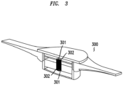
- Figure 3 depicts another view of a vestibular device 300 that utilizes springs as the elastic objects according to an embodiment of the present invention.
- the system 400 may comprise two vestibular devices 40 1a, b (similar to device 2 or 300) that may be integrated into, or connected to a first type of audio headphones 402 (e.g., headphones without noise cancellation circuitry).
- a user (not shown in Figure 4 ) has the option to just listen to music, listen to music and manipulate their vestibular, or just manipulate their vestibular system.
- the headphones 402 may comprise audio headphones that include noise cancellation circuitry.
- the headphones 402 may be integrated with, or connected to, the vestibular devices 401a, b so the user has the option to listen to music, listen to music and manipulate their vestibular, listen to music and cancel noise, manipulate their vestibular system and cancel noise, listen to music manipulate their vestibular system and cancel noise, just manipulate their vestibular system or just cancel noise.
- FIG 4 illustrates the use of more than one vestibular device. It should be understood that each of the systems described herein may include more than one vestibular device (e.g., at least two devices).
- the noise cancellation circuitry in the system 400 may also be used to reduce the level of audible sound caused by vibrations produced by the vestibular device 401 (e.g., a vestibular device described herein) while allowing substantially all other sounds to be received by a person's vestibular system.
- the system 400 may include noise cancellation circuitry that generates a signal (or signals) that is similar to the audible signals produced by the vestibular device 401, but is out of phase with such a signal (e.g., 180 degrees). Such an out of phase signal acts to reduce the signal level of such audible signals detected by a person's vestibular system so that a person may not hear the audible sounds.
- the vestibular devices 401a, b When used in conjunction with headphones 402 the vestibular devices 401a, b may be placed in a plurality of positions. One such position for each device 401a, b is located a distance away from a respective audio speaker 403a, b that are a part of the headphones 402, along the elongated portion 404 (e.g., band) of the headphones 402.
- Placement along the elongated portion 404 also takes advantage of the ergonomics of the elongated portion 404 (i.e., the shape of the human head is more consistent than the human ear).
- the vestibular devices 401a, b may be incorporated earcups of headphones 402that may be co-located with the speakers 403a, b so that the ornamental shape or profile of the headphones 402 are not affected
- the vestibular device 401 may be incorporated into an attachment which attaches and detaches to a pair of headphones so that the user may choose to have just the headphones or have the headphones with the vestibular device.
- a vestibular device described elsewhere hereon may be integrated into, or connected to a seat (car seat, office chair, etc.) and configured so that, for example, when a user's head rests against the seat the advantageous effects of the vestibular device are maximized.
- the vestibular device may be removably attached to the seat such that it can be removed and placed on the head of a user.
- a vestibular device may be integrated into, or connected to, a physical platform (e.g., a pad) that may be mounted in a vehicle at a position where an individual may rest their head on, or near, the vestibular device. Exemplary positions may be the seat of a vehicle, the window of a vehicle or a horizontal surface of a vehicle's rear seat.
- a vestibular device as described herein may be integrated into, or connected to, a pillow, travel pillow, or cushion (collectively “pillow"),
- the combination of pillow and vestibular device may be configured such that when a user rests their head on the vestibular device, and receives vibrations generated by the device, their head is still supported.
- a vestibular device described herein.
- One of these is a system that includes a vestibular device and a virtual reality device (e.g., headset).
- a mounting lattice can be configured to secure the vestibular device against a person's head so that the effects of the vestibular device (i.e., its vibrations) can be effective, or the vestibular device may be connected to the virtual reality headset such that it can be removed and placed on a person's head.
- a system 500 may include a vestibular device 501 described herein integrated into, or connected to, a headband 502.
- the headband 502 may comprise an elastic, Velcro, metal or plastic, or another material that permits the headband 502 to hold the vestibular device 501 (i.e., the vibration generating element of the device 501) anywhere on the head 503 of an individual in order to allow the signals for de-stimulating or masking the vestibular system of the individual
- the system 500 may be equipped with a power source (e.g., a battery) to power it (not shown in Figures 5 or 6 ) or it may be attached via a wire to another power source (e.g., AC or DC source, such as a battery pack; not shown in figures) which is not a part of the headband 502.
- the system 500 may include the necessary electrical driving circuitry to drive the vestibular device 501. Alternatively, such circuitry and power source may be connected to the vestibular device
- a system may include a vestibular device described herein that is integrated into, or connected to, glasses or sunglasses.
- the vestibular device may be attached to a part of glasses that make contact and rest on a person's car (e.g., temple tips).
- a power source e.g., battery
- signal driving circuitry e.g., signal driving circuitry or such circuitry and power source may be connected to the vestibular device by means known in the art.
- a system may include a vestibular device described herein that is integrated into, or connected to, a hat or cap (collectively "hat").
- the system may include a power source (e.g., battery) and electrical driving circuitry or such circuitry and power source may be connected to the system by means known in the art.
- a system may include a vestibular device described herein that may be integrated into, or connected to a hair accessory (an object that holds on to the hair for stability).
- the accessory may be ornamental or not.
- the system may include a power source (e.g., battery) and electrical driving circuitry or such circuitry and power source may be connected to the system by means known in the art.
- a system may comprise a vestibular device described herein integrated into, or connected to (a) a soldiers' helmet or any other form of helmet, or (b) a pilots' headset or any other type of headset.
- the system may include the necessary power source (e.g., battery) and electrical driving circuitry.
- Such a system may de-stimulate the vestibular system of a pilot, thus allowing the pilot to rely on an airborne vehicle's (e.g., a plane) instruments for orientation.
- a vestibular device described herein integrated into, or connected to, sensing means or sensor (collectively referred to as "sensor") (e.g., body sensor, environmental sensor, a temperature sensor, acceleration sensor, skin conduction sensor, heart rate monitor, a glucose sensor), electrodes which stimulate the vestibulocochlear nerve or a caloric stimulator such as the one described in U.S. Patent Application No. 20140309718 .
- sensor e.g., body sensor, environmental sensor, a temperature sensor, acceleration sensor, skin conduction sensor, heart rate monitor, a glucose sensor
- electrodes which stimulate the vestibulocochlear nerve or a caloric stimulator such as the one described in U.S. Patent Application No. 20140309718 .
- Figure 7 depicts a system 700 that includes a vestibular device 2 similar to the device in Figure I, for example.
- the system 700 may include a sensor 70, input/output (I/O) section 71, processor 72, memory 73, and transceiver 74.
- data from sensor 70 may be sent to the processor 72 and/or stored in memory 73 via I/O section 71.
- the data may consist of analog or digital signals output from the sensing means representative of real-world measurements of factors relevant to detecting or treating symptoms of maladies of the vestibular system.
- sensors may detect temperatures, noise levels, vibrations, accelerations/de-accelerations, velocities, pressures, moisture etc., and input this information into memory 73 or the processor 72.
- the processor 72 may be operable to execute instructions stored in its memory (not shown) or in memory 73 to control the operation of other elements depicted in Figure 7 .
- the processor 72 may adjust the operation of the signal generator 2c (e.g., adjust the output frequency, structure of the signal), amplifier 2b (e.g., increase or decrease amplification) and vibrational generating element 2a.
- the data may be stored for historical purposes in memory 73 and analyzed by processor 72 using additional instructions stored in its memory or memory 73 order to determine the proper settings of system 700 to customize the operation of system 700 for a particular individual and, thereby, customize the treatment of symptoms associated with maladies of the vestibular system.
- the data may be sent to a remote computing device via transceiver 74 for storage or further analysis.
- data and signals may be received from such a remote computing device (not shown in Figure 7 ) via transceiver 74, and then used by the processor 72 to control (e.g., adjust) the operation of elements of the system 700 to customize the treatment of symptoms associated with maladies of the vestibular system.
- the processor 72 may access instructions stored in its own memory or in memory 73 to make such adjustments.
- Additional embodiments include a system that includes a vestibular device described herein that is integrated into, or connected to a simulator, virtual reality device, augmented reality device, playground device, or amusement park ride device (e.g., the seat of an amusement park roller coaster, twisting ride, or ferris wheel, for example).
- a vestibular device described herein that is integrated into, or connected to a simulator, virtual reality device, augmented reality device, playground device, or amusement park ride device (e.g., the seat of an amusement park roller coaster, twisting ride, or ferris wheel, for example).
- the systems provided by the present invention may be effective at relieving the symptoms associated with vertigo, Meniere's disease, labyrinthitis, vestibular migraine, Benign Paraxial Positional Vertigo (BPPV), damage to the vestibular system, 'the spins' from alcohol or other drug consumption, tinnitus or any other vestibular or balance disorder.
- vertigo Meniere's disease, labyrinthitis, vestibular migraine, Benign Paraxial Positional Vertigo (BPPV), damage to the vestibular system, 'the spins' from alcohol or other drug consumption, tinnitus or any other vestibular or balance disorder.
- BPPV Benign Paraxial Positional Vertigo
- systems provided by the present invention described herein may be used to diagnose whether dizziness is brought on by a vestibular dysfunction or something else, such as a stroke.
- the systems provided by the present invention described herein may be used to relieve, distract, or mask the symptoms of tinnitus.
- the inventors have completed several tests with experimental devices that illustrate the effectiveness of using de-stimulating or masking signals to treat symptoms of maladies of the vestibular system. The following summarily describes these tests.
- test results were done with a plurality of test subjects (at least 10) without a control device or an experimental device.
- Each test subject sat in the back seat of a car and were asked to begin reading at the entrance ramp of the George Washington Parkway.
- a timer was started and the subjects were instructed to alert the proctors when they experienced the first symptoms of motion sickness.
- the windows were rolled down, and sufficient time was given for the subject to fully recover from any motion sickness experienced.
- the test was repeated using an experimental vestibular device or a control device that looked and sounded similar to the experimental device or an over the counter acupressure device.
- Table 1 sets forth recorded times (measured in seconds) that a test subject was able to ride without experiencing symptoms of motion sickness, and weightings based on how long it took the subject to experience motion sickness compared with a reference or baseline (i.e., the individual did not wear a control device or experimental device).
- Several test subjects using an experimental device ended the test before they felt any symptoms (e.g., nausea) due to muscle fatigue from holding it, or because the subject decided they did't getting sick and electing to end the test.
- the test results indicate that the experimental devices have, with a greater than 95% certainty, that they provide effective relief from the symptoms of motion sickness, an, in particular, delaying the onset of symptoms associated with motion sickness brought on by reading in a car.
- test subjects were exposed to two virtual reality environments which exposed them to angular and lateral motion. Initially, the test subjects were not provided with an experimental device. The time it took for the test subjects to develop discomforting symptoms was measured. Thereafter, the test subjects were provided with an experimental vestibular device, and the time until the test subjects developed discomforting symptoms was again measured. The results indicated that the test subjects provided with an experimental device could be exposed to the virtual environments without feeling discomforting symptoms for a time period that was twice as long as the time period during which the subjects were exposed to the same environments without using the experimental device (with many never feeling discomforting symptoms with the device).
- test subjects were asked immediately afterwards to fill out a conventional motion sickness questionnaire as well as again 10 minutes after the test. All test subjects who experienced discomfort expressed less motion sickness initially and a faster recovery from motion sickness while using an experimental device.
- test subject that suffered from tinnitus wore an experimental device reported their tinnitus was relived while the device was worn. It returned shortly after the device was removed.
Description
- Orientation, balance, position, and movement of a body can be determined by the brain through a combination of signals received from various parts of anatomy, including eyes, ears, and muscles. For example, movement of endolymph fluid in the vestibular system of the inner ear can be sensed by nerve cells with hair follicles to determine movement and orientation of the head, otoliths in the vestibular system of the inner ear sink in the direction of gravity and pull on hair follicles of nerve cells to aid in distinguishing up from down; horizontal and vertical visual patterns received by the eyes can assist with determinations of orientation, balance, and position; and differential strain on opposing neck muscles can help determine head position and orientation. When signals from these sources do not match, an individual can develop motion sickness, experience vertigo, or even become unconscious. Unmatched orientation, balance, position and movement signals can be the result of extreme or unfamiliar movement during, for example, travel in cars, trains, airplanes, and other modes of transportation, or can be the result of simulated perceived movement during, for example, 3D movies, 3D video games, and virtual reality devices.
- In a natural adaptive response, a brain can ignore sensory information in signals that are chaotic, not novel, or unintelligible. For example, it is believed that repetitive vibrations in the vestibular system of the inner ear decreases the amplitude of electrical signals sent to the cerebellum (see, for example, H. Sohmer et al. Effect of noise on the vestibular system - Vestibular evoked potential studies in rats. 2 Noise Health 41 (1999)).
- Vibrations can be very therapeutic. Accordingly, there exists massage devices used on several parts of the body to produce soothing sensations from vibrations. One technology that is used to create these vibrations is a surface or bone conduction transducer. However, when such devices are used on the head the noise they create can be irritating when used close to a person's ear. This occurs in large part because the resonant frequencies of the vibrations generated by such a transducer cause audible and irritating tones. Additionally, existing bone conduction transducers are inefficient when used to create powerful vibrations because they produce a large spectrum of frequencies when only a small narrow band may be needed.
- Accordingly, the present invention provides novel and non-obvious systems that improve the treatment of motion sickness as well as other maladies that are associated with the vestibular system of an individual.
- Additionally, the systems provided by the invention utilize novel and non-obvious vestibular system affecting/agitating/stimulating devices (e.g., transducers) that overcome the limitations of existing devices.
-
US2016/0089298 discloses a device for mitigating motion sickness and other responses to inconsistent sensory information. The device has a signal generator that is connected to a battery and generates a signal that contains a tone with a sine wave pattern. The signal contains an average output power level of between 100 and 150 decibels. A vibration-inducing element is connected to the signal generator and converts signal into physical vibrations. The battery, signal generator and vibration-inducing element are placed in a portable frame against the skull. -
-
Figure 1 depicts a simplified block diagram of an exemplary system according to an embodiment of the invention. -
Figure 2 depicts a cut-away view of an exemplary device according to an embodiment of the invention. -
Figure 3 depicts an alternative view of an exemplary device according to an embodiment of the invention. -
Figure 4 depicts an exemplary system combined with audio headphones according to an embodiment of the invention. -
Figures 5 and6 depict another exemplary system according to embodiment of the invention. -
Figure 7 depicts yet another exemplary system according to another embodiment of the invention. - The inventors recognized that a "noisy" signal from the vestibular system cannot be properly interpreted by the brain, prompting the brain to instead rely on signals from other sources, such as the eyes and muscles. Fewer signals to interpret allows the brain to determine orientation, balance, position, movement, or a combination thereof, with a smaller chance of unmatched signals, consequently reducing the likelihood that an individual may experience resulting detrimental physiological effects, such as motion sickness.
- Accordingly, the present invention makes use of this discovery to generate signals that de-stimulate the vestibular system of an individual. The present invention provides exemplary devices that generate such signals and apply them, for example, to the head (i.e., skull) of an individual so that the signals may travel to the vestibular system of an individual. When received by the vestibular system the signals effectively de-stimulate the vestibular system by, for example, masking other signals that stimulate the vestibular system.
- The systems and devices described herein may be combined or connected to detection circuitry for detecting nystagmus (i.e., shaky eye). Such a measurement may be used to measure how well the vibratory signals provided by systems and devices of the present invention de-stimulate the vestibular system by masking stimulating signals. Alternatively, instead of detecting a nystagmus, the detection circuitry may detect signals from the vestibulochochlear nerve itself.
- One exemplary embodiment is a system for reducing the symptoms of maladies of the vestibular system, where the system comprises a vestibular device operable to generate one or more vibratory signals at power levels that cause a de-stimulation of the vestibular system of an individual, wherein the device comprises (i) a signal generator for generating one or more initial signals; (ii) an amplifying section for receiving the one or more initial signals (e.g., a sine wave) and amplifying the signals by an amount sufficient to produce one or more signals that de-stimulate the vestibular system; and (iii) a vibration generating element (e.g., a transducer) operable to receive the one or more amplified signals and generate one or more fluctuating, vibration signals.
- An exemplary transducer may be operable to generate the one or more vibration signals, wherein a majority of the power in each of the vibratory signals is contained in a fundamental frequency of each of the vibration signals.
- In addition, the exemplary transducer may include, among other elements, a coil operable to generate a magnetic field and apply the field to a type of magnet, wherein the magnet is operable to oscillate at a resonant frequency to generate the one or more vibration signals.
- The systems and devices provided by the present invention may be customized for a given individual (e.g., patient) at a particular power and frequency of operation. Accordingly, an inventive device may include a power supply (e.g., battery), signal generator, amplifier, and battery charger.
- In accordance with one aspect of the invention, there is provided a system for reducing the symptoms of maladies of the vestibular system as defined by claim 1. Optional features are defined by the dependent claims.
- Exemplary embodiments of systems, devices and methods for reducing the symptoms of maladies related to the vestibular system, such as motion sickness, are described herein. Although specific exemplary embodiments are discussed herein, there is no intent to limit the scope of the present invention to such embodiments. To the contrary, the exemplary embodiments discussed herein are for illustrative purposes. Modified and alternative embodiments may be implemented without departing from the scope of the present invention. Said another way, the exemplary embodiments presented herein are only some of the many that fall within the scope of the present invention, it being practically impossible for the inventor to describe all the many possible exemplary embodiments and variations that fall within the scope of the present invention.
- For example, though the systems, devices and methods described herein focus on applying the inventive systems and methods close to the ear of an individual, this is for illustrative purposes only, it being further understood that the systems, devices and methods may be applied to many different parts of an individual's head.
- It should also be understood that one or more exemplary embodiments may be described as a process or method. Although a process/method may be described as sequential, such a process/method may be performed in parallel, concurrently or simultaneously. In addition, the order of each step within a process/method may be rearranged. A process/method may be terminated when completed, and may also include additional steps not included in a description of the process/method.
- As used herein, the term "and/or" includes all combinations of one or more of the associated listed items. As used herein, the singular forms "a," "an" and "the" are intended to include the plural form, unless the context and/or common sense indicates otherwise. It should be further understood that the terms "comprises", "comprising,", "includes" and/or "including", when used herein, specify the presence of stated features, systems, subsystems, steps, operations, elements, and/or components, but do not preclude the presence or addition of one or more other features, systems, subsystems, steps, operations, elements, components, and/or combinations thereof.
- When used herein the phrases "connection", "connected to", or similar phrases means an indirect or direct physical connection between at least two different parts of a system or device or means one part of a system or device subsumed within (and thereby connected to) at least one other part of a device. When one part of a system or device is described or depicted as being connected to another part, other well-known components used to facilitate such a connection may not be described or depicted because such components are well known to those skilled in the art.
- Yet further, when one part of a system or device is described or depicted as being connected to another part using "a connection" (or single line in a figure) it should be understood that practically speaking such a connection (line) may comprise (and many times will comprise) more than one physical connection or channel, may be omnidirectional or bi-directional, may or may not include separate data, formatting and signaling.
- It should be noted that the systems and devices illustrated in the figures are not drawn to scale, are not representative of an actual shape or size and are not representative of any actual device layout, manufacture's drawing or visual. Rather, the systems and devices are drawn to simply help explain the features, functions and processes of exemplary embodiments of the present invention described herein.
- As used herein, the term "embodiment" refers to one example of the present invention.
- The present invention provides for systems, devices and related methods which generates one or more de-stimulating signals sufficient to affect the vestibular function of an individual. This altered vestibular function may be perceived through quantitative measurements such as induced nystagmus and changes in vestibular evoked potentials or by qualitative measurements such as relief from motion sickness, virtual reality sickness, vertigo, or any other vestibular condition.
- One embodiment of the invention to mitigate motion sickness is by disrupting, controlling, or influencing anatomy of the vestibular system, such as, for example, otoliths, endolymph, and hair follicles. An embodiment of the invention may induce vibrations in the vestibular system, including otoliths and/or semicircular canals, of the inner ear, thereby masking the sensory information sent to the brain from the vestibular system. Because of the constant and non-informative nature of this masked sensory information, the brain, as part of a normal physiological response, may rely less on signals received from the vestibular system and rely more heavily on other sources, thereby mitigating motion sickness. The vibrations created may be constant or vary over a 1/3 octave range to ensure the body doesn't adapt to the masking. Another embodiment of the invention may induce vibrations in the vestibular system of the inner ear, thereby controlling the positions of otoliths, endolymph, hair follicles or combinations thereof, and, consequently, alter the sensory information in the signal sent from the vestibular system to the brain to mitigate motion sickness.
- In another embodiment, the signals generated by the systems and device may be de-stimulating, vibratory signals that are transmitted to the brain.
- The systems and devices described above and elsewhere herein may be combined or connected to detection circuitry for detecting nystagmus (i.e., shaky eye). Such a measurement may be used to measure how well the vibratory signals provided by the present invention masks the vestibular system. Alternatively, instead of detecting a nystagmus, the detection circuitry may detect signals from vestibular nerve itself.
- The systems and devices provided by the present invention may be customized for a given individual (e.g., patient) at a particular power and frequency of operation. Accordingly, an inventive system or device may include a power supply (e.g., battery), signal generator, amplifier, and battery charger.
- Referring now to
Figure 1 , there is depicted an exemplary system 1 for de-stimulating the vestibular system. As depicted the system 1 comprises avestibular device 2 operable to generate one or more vibratory signals (i.e., vibrations) at power levels that cause a de-stimulation of the vestibular system of an individual when the system 1 is placed on, or near, the vestibular system. In particular, thevestibular device 2 of the system 1 may be positioned on an individual's head where there is little tissue allowing the signal to propagate thru to the vestibular system (e.g., over the mastoid bone). - In one embodiment, the
vestibular device 2 may comprise avibration generating element 2a (e.g., a transducer) that is operable to produce one or more fluctuating, vibration signals at one or more harmonics of a frequency in the range 10 to 300 Hz, for example. The inventors believe that such signals de-stimulate the vestibular system, or alternatively may cause the system to be confused, by masking other signals that may stimulate the vestibular system. The one or more signals may take the form of a sine wave or a number of other signal types. - The present inventors conducted a number of experiments with experimental devices. The evidence obtained by the inventors indicates that when the system 1 generates vibratory signals (vibrations) at low frequencies it is important to ensure that the waveform (e.g., sine wave) of such a signal remains unchanged when pressure (force) is applied to the system 1, and in
particular device 2, as thedevice 2 is pressed to the skull of an individual. - In more detail, the
device 2 may further comprise asignal generator 2c for generating one or more initial signals (e.g. 50 to 67 Hz.) such as a pure sine wave and anamplifying section 2b for receiving the one or more signals generated by thegenerator 2a and amplifying the one or more signals by an amount (e.g. 0.5 watt to 3 watts) sufficient to produce one or more signals that de-stimulates the vestibular system. The so amplified signal is then provided to thevibration generating element 2a that, upon receiving the amplified signal generates the one or more vibratory signals. - In one experiment, the inventors conducted an experiment using a system similar to system 1 where a pure sine wave signal was generated by the combination of
generator 2c andamplifier 2b and then sent to thevibration generating element 2a (e.g., a transducer). Thereafter, no pressure was exerted. The result was that a pure sine wave was detected on a testing device. However, when pressure was applied, the pure sine wave signal that was generated changed its characteristics because much of the energy derived from the amplified electrical signal was physically converted from the signal's fundamental frequency to its higher harmonics. During further testing the inventors discovered that transducers which remained the most fundamental (i.e., where the majority of the power is contained in a fundamental frequency, and not in harmonics) were the most effective at de-stimulating the vestibular system in order to reduce the symptoms of motion sickness for individuals riding in cars and virtual reality sickness for those using virtual reality devices. Accordingly, the inventors concluded that transducers that are operable to generate one or more vibration signals, wherein a majority of the power in each of the vibratory signals is contained in a fundamental frequency of each of the vibration signals are highly desirable. Further, that transducers that are utilized within systems provided by the present invention should be operable to generate a signal of pure tone regardless of the power of the signal (i.e., a sine wave at a given signal). - Referring now to
Figure 2 there is depicted an exemplary vestibular device 2 (e.g., a transducer) according to one embodiment. As depicted, thedevice 2 may comprise a first type ofmagnet 20a,20b, a second type ofmagnet 23, acoil 24, a bushing 22c andpin 21. As power is applied to the device 2 (through means and connections known in the art, and omitted for the sake of clarity inFigure 2 ) using an electrical signal that comprises a sine wave or another type of signal structure at a desired frequency (e.g., 10 Hz to 300 Hz), thecoil 24 is operable to generate a magnetic field with an induced electrical current. The magnetic field in turn will apply a magnetic force onmagnet 23. The fields, when applied to themagnet 23, causes themagnet 23 to move as indicated by the labelled arrow "A" inFigure 2 . Substantially simultaneously,magnets 20a and 20b each create a constant magnetic field, each of which is applied to magnet 23 (i.e. North side of magnet 20a will face the North side ofmagnet 23 and the South side ofmagnet 20b will face the South side of magnet 23). These applied, opposing forces created by magnets 20a, b are operable to control themagnet 23 such that themagnet 23 oscillates around an equilibrium position where it naturally vibrates at a resonant frequency of (spring constant / mass ofmagnet 23, ^0.5 where the spring constant is defined as the restorative force divided by thedistance magnet 23 has moved from its equilibrium position) and generates the one or more vibration signals. In one embodiment, the induced electrical signal matches theresonant frequency magnet 23 vibrates at due tomagnets 20a and 20b, (i.e., it will cause themagnet 23 to oscillate or move back and forth, or up and down depending on your perspective) along the axis indicated by the labelled arrow "A". This axis may substantially correspond with the axis of thepin 21. - In an embodiment of the invention to ensure that the magnets 20a, b and 23 do not oscillate or wobble in an undesired fashion (along an axis other than that indicated by the labelled arrows "A"), which would affect the efficiency of the system and increase undesirable friction that causes secondary vibrations (i.e., a humming sound), the
magnet 23 is configured such that its motion is restricted by the rod/pin 21. In one embodiment, each of the magnets 20a, b is secured to theend caps 25a, b of thetransducer 2 with a glue, epoxy, or another form of adhesive,magnet 23 is fitted with a bushing 22c which smoothly moves over rod/pin 21 while restricting any motion that's not parallel to "A", and a glue, epoxy, or another form of adhesive may also be used to secure the rod/pin 21 to theend caps 25a, b through a fitted hole 22 a, b. - It should be understood that the magnets 20a, b are one example of elastic objects. In an alternative design, the magnets 20a, b may be replaced by other elastic objects which create a narrow resonance (defined in part by their spring constant). For example, the elastic objects may consist of springs of any form and material, where the springs may be supported by (i) cavities (not shown in
Figure 2 ) inend caps 25a, b. (ii) pins extruding from the end caps (not shown inFigure 2 ), (iii) silicon foam or foam of any other material (not shown inFigure 2 ), or (iv) are pieces of rubber or any another solid elastic material (not shown inFigure 2 ). When springs are used as the elastic objects a glue, epoxy, or any form of adhesive may be used to secure the springs to other parts of the device 2 (e.g., to the magnet, tubing, and/orend caps 25a, b). - In embodiments of the invention, the springs are operable to reduce the chances for the
magnet 23 to make contact with the inner diameter of thetubing 26 along an axis other than the axis represented by the labelled arrow "A", In embodiments, the rod/pin 21 and bushing 22c may be included for support or be excluded depending on the springs utilized (i.e., depending on whether the springs sufficiently restrict themagnet 23 motion). - In embodiments of the invention, the
tubing 26 may contain a lubricant, such as ferrofluid, Teflon, or another lubricant that reduces the friction that may occur when themagnet 23 may meet the inner diameter of thetubing 26. The less friction the "quieter" the device 2 (i.e., the less noise generated by such contact). Such lubricants may also be used to reduce the friction between the bushing and pin. - The present invention includes embodiments where the outer surface of the
tubing 26 and/orendcaps 25a, b are covered with a sound absorbing material. Further, in an embodiment one or more of theendcaps 25a, b may be covered with a friction reducing material, such as cork for example, so that when an endcap orendcaps 25a, b come in contact with a person's skin or body the contact is less abrasive than if theendcaps 25a, b where not covered by such material. Further, in an embodiment one or more of theendcaps 25a, b may be covered with a padded material, such as cork for example, so that when an endcap orendcaps 25a, b come in contact with a person's skin or body the contact is spread over a larger area reducing the pressure if theendcaps 25a, b where not covered by such material. - As described above, either magnets or springs may be used as the elastic objects. It should be understood, however, that magnets and springs are only two of the many types of elastic objects that may be used.
-
Figure 3 depicts another view of avestibular device 300 that utilizes springs as the elastic objects according to an embodiment of the present invention. - Referring now to
Figure 4 asystem 400 for reducing the effects of maladies related to the vestibular system (e.g., motion sickness) is shown. As shown thesystem 400 may comprise two vestibular devices 40 1a, b (similar todevice 2 or 300) that may be integrated into, or connected to a first type of audio headphones 402 (e.g., headphones without noise cancellation circuitry). In such an embodiment, a user (not shown inFigure 4 ) has the option to just listen to music, listen to music and manipulate their vestibular, or just manipulate their vestibular system. In another embodiment, theheadphones 402 may comprise audio headphones that include noise cancellation circuitry. Theheadphones 402 may be integrated with, or connected to, thevestibular devices 401a, b so the user has the option to listen to music, listen to music and manipulate their vestibular, listen to music and cancel noise, manipulate their vestibular system and cancel noise, listen to music manipulate their vestibular system and cancel noise, just manipulate their vestibular system or just cancel noise. - The embodiment depicted in
Figure 4 illustrates the use of more than one vestibular device. It should be understood that each of the systems described herein may include more than one vestibular device (e.g., at least two devices). - The noise cancellation circuitry in the
system 400 may also be used to reduce the level of audible sound caused by vibrations produced by the vestibular device 401 (e.g., a vestibular device described herein) while allowing substantially all other sounds to be received by a person's vestibular system. In more detail, because the physics of vibrational signals are predictable, thesystem 400 may include noise cancellation circuitry that generates a signal (or signals) that is similar to the audible signals produced by the vestibular device 401, but is out of phase with such a signal (e.g., 180 degrees). Such an out of phase signal acts to reduce the signal level of such audible signals detected by a person's vestibular system so that a person may not hear the audible sounds. - When used in conjunction with
headphones 402 thevestibular devices 401a, b may be placed in a plurality of positions. One such position for eachdevice 401a, b is located a distance away from a respective audio speaker 403a, b that are a part of theheadphones 402, along the elongated portion 404 (e.g., band) of theheadphones 402. This would allow the elements of thevestibular devices 401a, b, that are responsible for generating vibrational signals, to be a placed at positions aside, or on top of: a person's head at positions that have been shown to be effective for delivering the vibrational signals to the vestibular system (e.g., positioned on the mastoid, zygomatic arch, parietal bone, etc.). Placement along theelongated portion 404 also takes advantage of the ergonomics of the elongated portion 404 (i.e., the shape of the human head is more consistent than the human ear). - Alternatively, the
vestibular devices 401a, b may be incorporated earcups of headphones 402that may be co-located with the speakers 403a, b so that the ornamental shape or profile of theheadphones 402 are not affected, Alternatively, the vestibular device 401 may be incorporated into an attachment which attaches and detaches to a pair of headphones so that the user may choose to have just the headphones or have the headphones with the vestibular device. - Yet further, in another embodiment a vestibular device described elsewhere hereon may be integrated into, or connected to a seat (car seat, office chair, etc.) and configured so that, for example, when a user's head rests against the seat the advantageous effects of the vestibular device are maximized. Alternatively, the vestibular device may be removably attached to the seat such that it can be removed and placed on the head of a user. Still further, a vestibular device may be integrated into, or connected to, a physical platform (e.g., a pad) that may be mounted in a vehicle at a position where an individual may rest their head on, or near, the vestibular device. Exemplary positions may be the seat of a vehicle, the window of a vehicle or a horizontal surface of a vehicle's rear seat.
- Still further, a vestibular device as described herein may be integrated into, or connected to, a pillow, travel pillow, or cushion (collectively "pillow"), In such an embodiment, the combination of pillow and vestibular device may be configured such that when a user rests their head on the vestibular device, and receives vibrations generated by the device, their head is still supported.
- There are many more systems that may include a vestibular device described herein. One of these is a system that includes a vestibular device and a virtual reality device (e.g., headset). In one exemplary design, a mounting lattice can be configured to secure the vestibular device against a person's head so that the effects of the vestibular device (i.e., its vibrations) can be effective, or the vestibular device may be connected to the virtual reality headset such that it can be removed and placed on a person's head.
-
Figures 5 and6 depict additional embodiments of the invention. As depicted, asystem 500 may include avestibular device 501 described herein integrated into, or connected to, aheadband 502. Theheadband 502 may comprise an elastic, Velcro, metal or plastic, or another material that permits theheadband 502 to hold the vestibular device 501 (i.e., the vibration generating element of the device 501) anywhere on thehead 503 of an individual in order to allow the signals for de-stimulating or masking the vestibular system of the individual Thesystem 500 may be equipped with a power source (e.g., a battery) to power it (not shown inFigures 5 or6 ) or it may be attached via a wire to another power source (e.g., AC or DC source, such as a battery pack; not shown in figures) which is not a part of theheadband 502. Thesystem 500 may include the necessary electrical driving circuitry to drive thevestibular device 501. Alternatively, such circuitry and power source may be connected to thevestibular device 501 through means known in the art (e.g., electrical wires, optical fiber). - In a further embodiment, a system may include a vestibular device described herein that is integrated into, or connected to, glasses or sunglasses. In an embodiment, the vestibular device may be attached to a part of glasses that make contact and rest on a person's car (e.g., temple tips). As before, such a system may include a power source (e.g., battery) and signal driving circuitry or such circuitry and power source may be connected to the vestibular device by means known in the art.
- In a yet a further embodiment, a system may include a vestibular device described herein that is integrated into, or connected to, a hat or cap (collectively "hat"). The system may include a power source (e.g., battery) and electrical driving circuitry or such circuitry and power source may be connected to the system by means known in the art.
- In still a further embodiment, a system may include a vestibular device described herein that may be integrated into, or connected to a hair accessory (an object that holds on to the hair for stability). The accessory may be ornamental or not. By attaching the system to the hair of a person the vestibular device may make contact with the head of a person. The system may include a power source (e.g., battery) and electrical driving circuitry or such circuitry and power source may be connected to the system by means known in the art.
- In a further embodiment, a system may comprise a vestibular device described herein integrated into, or connected to (a) a soldiers' helmet or any other form of helmet, or (b) a pilots' headset or any other type of headset. As before, the system may include the necessary power source (e.g., battery) and electrical driving circuitry. Such a system may de-stimulate the vestibular system of a pilot, thus allowing the pilot to rely on an airborne vehicle's (e.g., a plane) instruments for orientation.
- Alternative embodiments of the present invention provide for systems that include a vestibular device described herein integrated into, or connected to, sensing means or sensor (collectively referred to as "sensor") (e.g., body sensor, environmental sensor, a temperature sensor, acceleration sensor, skin conduction sensor, heart rate monitor, a glucose sensor), electrodes which stimulate the vestibulocochlear nerve or a caloric stimulator such as the one described in
U.S. Patent Application No. 20140309718 . - For example,
Figure 7 depicts asystem 700 that includes avestibular device 2 similar to the device in Figure I, for example. In addition, thesystem 700 may include asensor 70, input/output (I/O)section 71,processor 72,memory 73, andtransceiver 74. In an embodiment, data fromsensor 70 may be sent to theprocessor 72 and/or stored inmemory 73 via I/O section 71. The data may consist of analog or digital signals output from the sensing means representative of real-world measurements of factors relevant to detecting or treating symptoms of maladies of the vestibular system. For example, sensors may detect temperatures, noise levels, vibrations, accelerations/de-accelerations, velocities, pressures, moisture etc., and input this information intomemory 73 or theprocessor 72. Thereafter, theprocessor 72 may be operable to execute instructions stored in its memory (not shown) or inmemory 73 to control the operation of other elements depicted inFigure 7 . For example, theprocessor 72 may adjust the operation of thesignal generator 2c (e.g., adjust the output frequency, structure of the signal),amplifier 2b (e.g., increase or decrease amplification) andvibrational generating element 2a. Yet further, the data may be stored for historical purposes inmemory 73 and analyzed byprocessor 72 using additional instructions stored in its memory ormemory 73 order to determine the proper settings ofsystem 700 to customize the operation ofsystem 700 for a particular individual and, thereby, customize the treatment of symptoms associated with maladies of the vestibular system. Still further, the data may be sent to a remote computing device viatransceiver 74 for storage or further analysis. Conversely, data and signals may be received from such a remote computing device (not shown inFigure 7 ) viatransceiver 74, and then used by theprocessor 72 to control (e.g., adjust) the operation of elements of thesystem 700 to customize the treatment of symptoms associated with maladies of the vestibular system. In an embodiment, theprocessor 72 may access instructions stored in its own memory or inmemory 73 to make such adjustments. - Additional embodiments include a system that includes a vestibular device described herein that is integrated into, or connected to a simulator, virtual reality device, augmented reality device, playground device, or amusement park ride device (e.g., the seat of an amusement park roller coaster, twisting ride, or ferris wheel, for example).
- In addition to relieving the symptoms associated with motion sickness, the systems provided by the present invention may be effective at relieving the symptoms associated with vertigo, Meniere's disease, labyrinthitis, vestibular migraine, Benign Paraxial Positional Vertigo (BPPV), damage to the vestibular system, 'the spins' from alcohol or other drug consumption, tinnitus or any other vestibular or balance disorder.
- Further, the systems provided by the present invention described herein may be used to diagnose whether dizziness is brought on by a vestibular dysfunction or something else, such as a stroke.
- Further, the systems provided by the present invention described herein may be used to relieve, distract, or mask the symptoms of tinnitus. The inventors have completed several tests with experimental devices that illustrate the effectiveness of using de-stimulating or masking signals to treat symptoms of maladies of the vestibular system. The following summarily describes these tests.
- To ensure consistent testing conditions, a portion of the George Washington Parkway in the Washington, D.C. area and its surrounding roads were used as a testing track. These roads have curves and traffic signs which exposed test subjects to both stop/go and side-to-side accelerations which commonly induce motion sickness. These roads also lacked stop lights or any irregular traffic patterns which could cause inconsistent testing. Throughout the track, the driver had certain milestones to check speed in order to, again, keep the testing as consistent as possible.
- The tests were done with a plurality of test subjects (at least 10) without a control device or an experimental device. Each test subject sat in the back seat of a car and were asked to begin reading at the entrance ramp of the George Washington Parkway. A timer was started and the subjects were instructed to alert the proctors when they experienced the first symptoms of motion sickness. At that moment the timer was stopped, the windows were rolled down, and sufficient time was given for the subject to fully recover from any motion sickness experienced. Once a full recovery had occurred the test was repeated using an experimental vestibular device or a control device that looked and sounded similar to the experimental device or an over the counter acupressure device.
- The tests without an experimental device or control device were always conducted first. Thereafter, to determine the order of the other tests with a control device or an experimental device a coin was flipped when the choice was between an experimental device and similar control device or a six-sided di was used to decide the order when the choice was between an experimental device, control device or acupressure device.
- Table 1 below sets forth recorded times (measured in seconds) that a test subject was able to ride without experiencing symptoms of motion sickness, and weightings based on how long it took the subject to experience motion sickness compared with a reference or baseline (i.e., the individual did not wear a control device or experimental device). Several test subjects using an experimental device ended the test before they felt any symptoms (e.g., nausea) due to muscle fatigue from holding it, or because the subject decided they weren't getting sick and electing to end the test. The 'Did Nausea End the Trial' column indicates whether the subject eventually felt motion sickness while using an experimental device or if the test ended for other reasons:
TABLE I Nothing Control Vibe Psiband W control W Vibe W Psiband Did Nausea End the Trial Subject 1 220 256 558 1.16 2.54 N Subject 2 326 246 523 0.75 1.60 Y Subject 3 48 97 367 2.02 7.65 Y Subject 4 296 264 701 0.89 2.37 N Subject 5 232 373 693 1.61 2.99 Y Subject 6 153 163 424 1.07 2.77 N Subject 7 101 94 356 0.93 3.52 Y Subject 8 206 195 393 0.95 1.91 N Subject 9 103 112 441 107 1.09 4.28 1.04 N Subject 10 138 192 324 102 1.39 2.35 0.74 Y - The results from the tests indicate that the experimental devices provided relief from the symptoms of motion sickness. With only one exception, all test subjects were able to travel at least twice as long with an experimental device without experiencing the symptoms of motion sickness as compared to the tests where they did not use an experimental device or a control device (subject 8 ended the test slightly before the 2x mark due to muscle fatigue). From these experiments, and using the equation provided by the National Institutes of Health (Equation (1) below), the inventors have a confidence level of 95% that the experimental devices provide effective treatment for motion sickness.


- Using Equation (1) the sample size applicable to the test results above were calculated as follows:

- With the current sample set being greater than 7.84 (i.e., 8) the test results indicate that the experimental devices have, with a greater than 95% certainty, that they provide effective relief from the symptoms of motion sickness, an, in particular, delaying the onset of symptoms associated with motion sickness brought on by reading in a car.
- An additional 30 test subjects were asked to perform tasks in the backseat of a car, boat, train, and plane which typically induced motion sickness while wearing an experimental vestibular device for a minimum of 20 minutes. All but one test subject indicated that their discomfort was significantly reduced or eliminated.
- A plurality of test subjects were exposed to two virtual reality environments which exposed them to angular and lateral motion. Initially, the test subjects were not provided with an experimental device. The time it took for the test subjects to develop discomforting symptoms was measured. Thereafter, the test subjects were provided with an experimental vestibular device, and the time until the test subjects developed discomforting symptoms was again measured. The results indicated that the test subjects provided with an experimental device could be exposed to the virtual environments without feeling discomforting symptoms for a time period that was twice as long as the time period during which the subjects were exposed to the same environments without using the experimental device (with many never feeling discomforting symptoms with the device).
- A plurality of test subjects 'rode' virtual roller coasters for a set amount of time both with, and without, an experimental device. In each scenario, the test subjects were asked immediately afterwards to fill out a conventional motion sickness questionnaire as well as again 10 minutes after the test. All test subjects who experienced discomfort expressed less motion sickness initially and a faster recovery from motion sickness while using an experimental device.
- Five test subjects who suffered from vertigo were tested. Two of them suffered from vestibular migraine, one had not identified the cause, and two were caused by alcohol consumption. An experimental device provided immediate reduction in symptoms in all cases. The symptoms returned soon after the experimental device was removed and were reduced again when the device was reapplied.
- A test subject that suffered from tinnitus wore an experimental device reported their tinnitus was relived while the device was worn. It returned shortly after the device was removed.
Claims (12)
- A system (1) for reducing the symptoms of maladies of the vestibular system comprising:one or more vestibular devices (2), each device (2) operable to generate one or more vibratory signals that cause a de-stimulation or masking of the vestibular system of an individual, wherein each of the one or more vestibular devices (2) comprises:a signal generator (2c) for generating one or more initial signals;an amplifying section (2b) for receiving the one or more initial signals and amplifying the one or more initial signals by an amount sufficient to produce one or more amplified signals that de-stimulate the vestibular system; anda bone conduction transducer (2a) operable to receive the one or more amplified signals and generate the one or more vibratory signals, the bone conduction transducer (2a) operable to generate the one or more vibratory signals having a majority of power contained in a fundamental frequency of the one or more vibratory signals, the one or more vibratory signals including signals at one or more harmonics of the fundamental frequency in the range 10 to 300 Hz,the one or more vestibular devices (2) configured to be positioned on a head of the individual such that the one or more vibratory signals are allowed to propagate through to the vestibular system over bone.
- The system as in claim 1, wherein the bone conduction transducer comprises:
a coil operable to generate a magnetic field in response to receiving the one or more amplified signals. - The system as in claim 2, wherein the bone conduction transducer includes:a magnet configured to oscillate along an axis;a rod configured to enable motion of the magnet along a direction parallel to the axis and to restrict motion of the magnet in a direction not parallel to the axis; andbucking magnets configured to apply opposing forces upon the magnet such that the magnet oscillates about an equilibrium position.
- The system as in claim 1, further comprising a band, wherein the band is configured to position the one or more vestibular devices at positions that enable the one or more vibratory signals to propagate through bone to the vestibular system.
- The system as in claim 1, further comprising at least one of a headband, an audio headphone, an earcup, a car seat, a pillow, a virtual reality device, glasses, a hat, a hair accessory, a helmet, or a headset,
wherein the one or more vestibular devices are integrated into, or connected to, the at least one of: the headband, the audio headphone, the earcup, the car seat, the pillow, the virtual reality device, the glasses, the hat, the hair accessory, the helmet, or the headset. - The system as in claim 1, further comprising:a sensor, wherein the one or more vestibular devices are integrated into, or connected to, the sensor, the sensor configured to measure one or more factors including at least one of temperatures, noise levels, vibrations, accelerations, de-accelerations, velocities, pressures, or moisture; anda processor configured to receive information from the sensor indicative of the one or more factors and control operation of at least one of the signal generator, the amplifier, or the bone conduction transducer of each of the one or more vestibular devices based on the information.
- The system as in claim 1, where the system is configured to reduce symptoms of at least one of motion sickness, dizziness, virtual reality sickness, vertigo or tinnitus.
- The system as in claim 1, wherein the bone conduction transducer includes:a magnet configured to oscillate about an equilibrium position; anda spring secured to the magnet, and the one or more vibratory signals are resonant frequencies of the spring and the magnet.
- The system as in claim 1, wherein the bone conduction transducer includes a padded material such that, when the bone conduction transducer comes into contact with a skin or body of the individual, the contact is spread over a larger area to reduce pressure.
- The system as in claim 1, wherein the bone conduction transducer includes a friction reducing material such that, when the bone conduction transducer comes into contact with a kin or body of the individual, the contact is less abrasive.
- The system as in claim 1, wherein the bone conduction transducer includes:a magnet configured to oscillate about an equilibrium position;one or more endcaps; andone or more springs secured to the one or more endcaps and the magnet, the one or more springs configured to apply forces upon the magnet to control the oscillation of the magnet about the equilibrium position.
- The system as in claim 1, wherein the bone conduction transducer is configured to deliver the one or more vibratory signals to the portion of the head of the individual such that the one of more vibratory signals propagate to the otoliths, endolymph, and hair follicles of the vestibular system.
Applications Claiming Priority (3)
| Application Number | Priority Date | Filing Date | Title |
|---|---|---|---|
| US201662421708P | 2016-11-14 | 2016-11-14 | |
| US15/481,457 US20180133102A1 (en) | 2016-11-14 | 2017-04-07 | Devices And Methods For Reducing The Symptoms Of Maladies Of The Vestibular System |
| PCT/US2017/061520 WO2018089994A1 (en) | 2016-11-14 | 2017-11-14 | Devices and methods for reducing the symptoms of maladies of the vestibular system |
Publications (3)
| Publication Number | Publication Date |
|---|---|
| EP3538050A1 EP3538050A1 (en) | 2019-09-18 |
| EP3538050A4 EP3538050A4 (en) | 2020-06-03 |
| EP3538050B1 true EP3538050B1 (en) | 2023-10-18 |
Family
ID=62107072
Family Applications (1)
| Application Number | Title | Priority Date | Filing Date |
|---|---|---|---|
| EP17868920.4A Active EP3538050B1 (en) | 2016-11-14 | 2017-11-14 | Devices and methods for reducing the symptoms of maladies of the vestibular system |
Country Status (7)
| Country | Link |
|---|---|
| US (1) | US20180133102A1 (en) |
| EP (1) | EP3538050B1 (en) |
| JP (1) | JP2020501852A (en) |
| CN (2) | CN115089470A (en) |
| AU (1) | AU2017357123B2 (en) |
| CA (1) | CA3043501A1 (en) |
| WO (1) | WO2018089994A1 (en) |
Families Citing this family (13)
| Publication number | Priority date | Publication date | Assignee | Title |
|---|---|---|---|---|
| US11213641B2 (en) | 2016-09-14 | 2022-01-04 | Healthy Humming, LLC | Therapeutic device for treatment of conditions relating to the sinuses, nasal cavities, ear, nose and throat |
| US11432993B2 (en) | 2016-09-14 | 2022-09-06 | Healthy Humming, LLC | Therapeutic device for treatment of conditions relating to the sinuses, nasal cavities, ear, nose and throat |
| US11305077B2 (en) | 2016-09-14 | 2022-04-19 | Healthy Humming, LLC | Therapeutic device for treatment of conditions relating to the sinuses, nasal cavities, ear, nose and throat |
| WO2018053079A1 (en) * | 2016-09-14 | 2018-03-22 | Bogan Consulting Services, P.A. | Therapeutic device for treatment of conditions relating to the sinuses, nasal cavities, ear, nose and throat |
| US10398897B2 (en) | 2016-11-14 | 2019-09-03 | Otolith Sound Inc. | Systems, devices, and methods for treating vestibular conditions |
| US11284205B2 (en) | 2016-11-14 | 2022-03-22 | Otolith Sound Inc. | Systems, devices, and methods for treating vestibular conditions |
| JP7191400B2 (en) * | 2018-05-31 | 2022-12-19 | 国立大学法人東海国立大学機構 | vestibular stimulator, dizziness treatment device, health promotion device |
| US11586291B2 (en) * | 2019-05-12 | 2023-02-21 | NeuroHaptics, Inc. | Motion sickness reduction device |
| US11275441B2 (en) * | 2019-05-12 | 2022-03-15 | Neurohaptics, Inc | Motion sickness reduction, directional indication, and neural rehabilitation device |
| US20240061510A1 (en) * | 2019-05-12 | 2024-02-22 | NeuroHaptics, Inc. | Motion sickness reduction, directional indication, and neural rehabilitation device |
| CA3140839A1 (en) * | 2019-06-07 | 2020-12-10 | Carlos Roberto CAMOZZI | Vibration generator |
| CN112353559B (en) * | 2020-10-28 | 2022-10-28 | 宜昌市中心人民医院(三峡大学第一临床医学院、三峡大学附属中心人民医院) | Ear-nose-throat department auditory canal nursing auxiliary device |
| WO2024014055A1 (en) * | 2022-07-13 | 2024-01-18 | 国立大学法人東海国立大学機構 | Vestibular function improvement device, drunkenness stimulation application system, and program |
Family Cites Families (76)
| Publication number | Priority date | Publication date | Assignee | Title |
|---|---|---|---|---|
| US4354067A (en) * | 1978-05-17 | 1982-10-12 | Bodysonic Kabushiki Kaisha | Audio-band electromechanical vibration converter |
| US4222393A (en) * | 1978-07-28 | 1980-09-16 | American Tinnitus Association | Tinnitus masker |
| JPS62231663A (en) * | 1986-04-01 | 1987-10-12 | 林原 健 | Vibration stimulation apparatus |
| EP0298661B1 (en) * | 1987-07-08 | 1994-06-15 | Kabushiki Kaisha Hayashibara Seibutsu Kagaku Kenkyujo | Novel vibrator system and vibrotherapeutic device using the same |
| DE8815877U1 (en) * | 1988-12-22 | 1989-04-27 | Junker, Franz, 7505 Ettlingen, De | |
| DE4014872A1 (en) * | 1990-05-09 | 1991-11-14 | Toepholm & Westermann | TINNITUS MASKING DEVICE |
| US5323468A (en) * | 1992-06-30 | 1994-06-21 | Bottesch H Werner | Bone-conductive stereo headphones |
| US5403262A (en) * | 1993-03-09 | 1995-04-04 | Microtek Medical, Inc. | Minimum energy tinnitus masker |
| US5611771A (en) * | 1994-11-14 | 1997-03-18 | Sharper Image Corporation | Head mounted pulse action facial massager |
| US5692056A (en) * | 1994-12-07 | 1997-11-25 | Gardner; William A. | Method and apparatus for intracranial noise suppression |
| US5795287A (en) * | 1996-01-03 | 1998-08-18 | Symphonix Devices, Inc. | Tinnitus masker for direct drive hearing devices |
| EP0820211B1 (en) * | 1996-07-09 | 2001-09-19 | Siemens Audiologische Technik GmbH | Programmable hearing aid |
| US5788656A (en) * | 1997-02-28 | 1998-08-04 | Mino; Alfonso Di | Electronic stimulation system for treating tinnitus disorders |
| US6193677B1 (en) * | 1997-08-14 | 2001-02-27 | B.R.S. Capital, Inc. | Sonic percussor device |
| CA2248642A1 (en) * | 1997-10-24 | 1999-04-24 | Axel F. Brisken | Apparatus and method for determining individual sensitivity to ultrasonic signals |
| US6068590A (en) * | 1997-10-24 | 2000-05-30 | Hearing Innovations, Inc. | Device for diagnosing and treating hearing disorders |
| JPH11165128A (en) * | 1997-12-04 | 1999-06-22 | Namiki Precision Jewel Co Ltd | Driving device of vibration actuator |
| US6217508B1 (en) * | 1998-08-14 | 2001-04-17 | Symphonix Devices, Inc. | Ultrasonic hearing system |
| US20010051776A1 (en) * | 1998-10-14 | 2001-12-13 | Lenhardt Martin L. | Tinnitus masker/suppressor |
| US6077237A (en) * | 1998-11-06 | 2000-06-20 | Adaboy, Inc. | Headset for vestibular stimulation in virtual environments |
| US6210321B1 (en) * | 1999-07-29 | 2001-04-03 | Adm Tronics Unlimited, Inc. | Electronic stimulation system for treating tinnitus disorders |
| JP3344385B2 (en) * | 1999-10-22 | 2002-11-11 | ヤマハ株式会社 | Vibration source drive |
| JP2003274468A (en) * | 2002-03-14 | 2003-09-26 | Tamagawa Kasei:Kk | Low frequency sound amplifying oscillator |
| US20030195588A1 (en) * | 2002-04-16 | 2003-10-16 | Neuropace, Inc. | External ear canal interface for the treatment of neurological disorders |
| US20100268125A9 (en) * | 2002-07-03 | 2010-10-21 | Epley Research, L.L.C. | Head-stabilized medical apparatus, system and methodology |
| JP3895674B2 (en) * | 2002-11-29 | 2007-03-22 | アルプス電気株式会社 | Vibration generator |
| US7933654B2 (en) * | 2002-12-17 | 2011-04-26 | Massachusetts Eye & Ear Infirmary | Vestibular stimulator |
| AT413077B (en) * | 2003-08-29 | 2005-11-15 | Othegraven Achim Von | THERAPEUTIC TREATMENT DEVICE |
| US7702114B2 (en) * | 2003-09-16 | 2010-04-20 | Koninklijke Philips Electronics N.V. | High efficiency audio transducer |
| WO2005072168A2 (en) * | 2004-01-20 | 2005-08-11 | Sound Techniques Systems Llc | Method and apparatus for improving hearing in patients suffering from hearing loss |
| WO2005117797A2 (en) * | 2004-05-26 | 2005-12-15 | The Metrohealth System | Method and apparatus for relief of headache |
| US20060020161A1 (en) * | 2004-07-20 | 2006-01-26 | James Mageras | Method and device for auditory stimulation for therapeutic application |
| JP2008092460A (en) * | 2006-10-04 | 2008-04-17 | Namiki Precision Jewel Co Ltd | Bone conduction speaker |
| MY150957A (en) * | 2007-01-10 | 2014-03-31 | Winkler Peter Anthony | Tinnitus treatment |
| US9597231B2 (en) * | 2007-01-10 | 2017-03-21 | TIPA Tinnitus Corporation PTY LTD. | Tinnitus treatment |
| US20090005713A1 (en) * | 2007-02-12 | 2009-01-01 | Podrazhansky Yury M | Method and Device for Using Vibroacoustical Stimulation to Treat Target Tissue Areas of Living Organisms |
| WO2009029040A1 (en) * | 2007-08-31 | 2009-03-05 | Tore Persson | Methods and devices for the treatment of tinnitus, anosmia and nerve injury |
| US8801591B1 (en) * | 2007-11-28 | 2014-08-12 | Vincent J. Lasorso, Jr. | Physical therapy whole sound frequencies device and method of using the same |
| US8849407B1 (en) * | 2008-01-04 | 2014-09-30 | Yuri P. Danilov | Non-invasive neuromodulation (NINM) for rehabilitation of brain function |
| US8167826B2 (en) * | 2009-02-03 | 2012-05-01 | Action Research Co., Ltd. | Vibration generating apparatus and method introducing hypersonic effect to activate fundamental brain network and heighten aesthetic sensibility |
| US10112029B2 (en) * | 2009-06-19 | 2018-10-30 | Integrated Listening Systems, LLC | Bone conduction apparatus and multi-sensory brain integration method |
| US8608638B2 (en) * | 2009-09-22 | 2013-12-17 | The Regents Of The University Of California | Methods and systems for treating tinnitus |
| US8463389B1 (en) * | 2010-03-31 | 2013-06-11 | Richard Oths | Multi-sensory system and method for providing neuromuscular stimulation |
| KR101133415B1 (en) * | 2010-05-14 | 2012-04-09 | 삼성전기주식회사 | A linear vibrator |
| US9461529B2 (en) * | 2010-09-01 | 2016-10-04 | Mor Efrati | Tactile low frequency transducer |
| EP2661306B1 (en) * | 2011-01-05 | 2020-05-06 | Stefanie Lattner | Apparatus for treating various neurological conditions |
| JP2012165129A (en) * | 2011-02-04 | 2012-08-30 | Jvc Kenwood Corp | Electroacoustic transducer |
| WO2012116130A1 (en) * | 2011-02-24 | 2012-08-30 | Vibrant Med-El Hearing Technology Gmbh | Mri safe actuator for implantable floating mass transducer |
| US20120302929A1 (en) * | 2011-05-23 | 2012-11-29 | Vitaly Tkachenko | Head mounted pulse action facial and head massager band |
| JP5840427B2 (en) * | 2011-09-09 | 2016-01-06 | アルプス電気株式会社 | Vibration generator |
| DE102012002436B4 (en) * | 2012-02-08 | 2014-08-21 | Forschungszentrum Jülich GmbH | Apparatus for calibrating a non-invasive desynchronizing neurostimulation |
| ES2912384T3 (en) * | 2012-02-28 | 2022-05-25 | Ana Maria Soza | Methods, devices and systems for the diagnosis and treatment of mood disorders |
| US20140018713A1 (en) * | 2012-07-05 | 2014-01-16 | Resonant Systems, Inc. | Personal vibration appliance |
| CN202721792U (en) * | 2012-08-02 | 2013-02-06 | 北京美尔斯通科技发展股份有限公司 | Wireless headset with combination of bone conduction and air conduction |
| JP6276511B2 (en) * | 2013-03-15 | 2018-02-07 | リオン株式会社 | Electromechanical transducer and electroacoustic transducer |
| US20160051793A1 (en) * | 2013-04-01 | 2016-02-25 | Motion Therapeutics Inc. | A method and apparatus for mediating proprioceptive skin and body sensors, vision, vestibular and somato-sensation acting in combination with brain function or neurosensory-motor system function |
| KR20160004314A (en) * | 2013-04-23 | 2016-01-12 | 다이치 메디컬 씨오., 엘티디. | Portable device capable of treating meniere's disease and symptoms similar thereto |
| US9895097B2 (en) * | 2013-05-13 | 2018-02-20 | Ear and Skull Base Center, P.C. | Systems and methods for delivering bone conduction stimuli to and for measuring gravitation receptor functions of the inner ear |
| US20140363003A1 (en) * | 2013-06-09 | 2014-12-11 | DSP Group | Indication of quality for placement of bone conduction transducers |
| US9154887B2 (en) * | 2013-08-09 | 2015-10-06 | Otorix AB | Bone conduction hearing aid system |
| EP4040805A3 (en) * | 2013-08-09 | 2022-10-05 | MED-EL Elektromedizinische Geräte GmbH | Bone conduction hearing aid system |
| JPWO2015040832A1 (en) * | 2013-09-20 | 2017-03-02 | パナソニックIpマネジメント株式会社 | Bone conduction speaker and bone conduction headphone device |
| CN106572940B (en) * | 2014-03-19 | 2019-12-06 | 科帕动物保健公司 | Sensory stimulation or monitoring device for the back of the neck |
| KR101635266B1 (en) * | 2014-07-10 | 2016-07-01 | 한림대학교 산학협력단 | Galvanic vestibular stimulation system for reducing cyber-sickness in 3d virtual reality environment and method thereof |
| US20160089298A1 (en) * | 2014-09-29 | 2016-03-31 | Otolith Sound Inc | Device for Mitigating Motion Sickness and Other Responses to Inconsistent Sensory Information |
| CN104490517A (en) * | 2014-12-26 | 2015-04-08 | 秦皇岛嘎哈医疗电子仪器有限公司 | Ear disease therapeutic apparatus |
| US9999835B2 (en) * | 2015-02-05 | 2018-06-19 | Sony Interactive Entertainment Inc. | Motion sickness monitoring and application of supplemental sound to counteract sickness |
| US9648412B2 (en) * | 2015-02-06 | 2017-05-09 | Skullcandy, Inc. | Speakers and headphones related to vibrations in an audio system, and methods for operating same |
| US20160256347A1 (en) * | 2015-03-05 | 2016-09-08 | Ronald ZIMMERMANN | Ear massage device |
| US20160277821A1 (en) * | 2015-03-19 | 2016-09-22 | Panasonic Intellectual Property Management Co., Ltd. | Vibration headphones |
| CN104873370A (en) * | 2015-05-05 | 2015-09-02 | 青岛帮尼达新产品技术开发咨询有限公司 | Mouth yoke type mask used for protecting mouth sexual intercourse and improving sexual fun |
| CN104873374B (en) * | 2015-05-12 | 2016-09-07 | 邹静 | A kind of coupling device between low-frequency vibration source and the mastoid process treating peripheral vertigo |
| CN104967935A (en) * | 2015-06-12 | 2015-10-07 | 苏州佑克骨传导科技有限公司 | Large-power oscillator suitable for bone conduction earphone |
| CN205142506U (en) * | 2015-08-13 | 2016-04-06 | 深圳市韶音科技有限公司 | Improve osteoacusis speaker that osteoacusis speaker leaks sound |
| BR112018002854B1 (en) * | 2015-08-13 | 2024-02-06 | Shenzhen Shokz Co., Ltd | OSTEOCONDUCTION METHODS AND SPEAKER |
| US20170171677A1 (en) * | 2015-12-11 | 2017-06-15 | Turtle Beach Corporation | Tinnitus treatment systems and methods |
-
2017
- 2017-04-07 US US15/481,457 patent/US20180133102A1/en not_active Abandoned
- 2017-11-14 JP JP2019547218A patent/JP2020501852A/en active Pending
- 2017-11-14 AU AU2017357123A patent/AU2017357123B2/en active Active
- 2017-11-14 CN CN202210558242.7A patent/CN115089470A/en active Pending
- 2017-11-14 EP EP17868920.4A patent/EP3538050B1/en active Active
- 2017-11-14 CN CN201780083234.9A patent/CN110381912B/en active Active
- 2017-11-14 WO PCT/US2017/061520 patent/WO2018089994A1/en active Application Filing
- 2017-11-14 CA CA3043501A patent/CA3043501A1/en active Pending
Also Published As
| Publication number | Publication date |
|---|---|
| US20180133102A1 (en) | 2018-05-17 |
| CN115089470A (en) | 2022-09-23 |
| AU2017357123A1 (en) | 2019-06-20 |
| EP3538050A1 (en) | 2019-09-18 |
| AU2017357123B2 (en) | 2023-06-08 |
| EP3538050A4 (en) | 2020-06-03 |
| CA3043501A1 (en) | 2018-05-17 |
| CN110381912A (en) | 2019-10-25 |
| JP2020501852A (en) | 2020-01-23 |
| CN110381912B (en) | 2022-06-07 |
| WO2018089994A1 (en) | 2018-05-17 |
Similar Documents
| Publication | Publication Date | Title |
|---|---|---|
| EP3538050B1 (en) | Devices and methods for reducing the symptoms of maladies of the vestibular system | |
| US10702694B2 (en) | Systems, devices, and methods for treating vestibular conditions | |
| JP2024045228A (en) | Systems, devices and methods for treating vestibular abnormalities | |
| US20090216070A1 (en) | Apparatus and method of relaxation therapy | |
| KR101372546B1 (en) | apparatus and method for reinforcing effective brain wave using sound volume | |
| WO2015028480A1 (en) | Pain relieving stimulation system | |
| JPH11155955A (en) | Phobia treatment equipment | |
| US20220279292A1 (en) | Systems, devices, and methods for treating vestibular conditions | |
| US11185692B2 (en) | Light touch therapeutic headset | |
| KR20180116653A (en) | Combined sensation wearable device treating and rehabilitating dizziness | |
| JP2014113362A (en) | Transcranial magnetic stimulation device | |
| WO2015173752A1 (en) | Pressure application device | |
| EP4259061A1 (en) | Wearable device for vibrotactile and/or thermal nerve stimulation | |
| JP2022533953A (en) | Systems, devices and methods for treating vestibular conditions | |
| US20210402174A1 (en) | Light touch therapuetic earbuds | |
| Hwang et al. | Enhancing Seamless Walking in Virtual Reality: Application of Bone-Conduction Vibration in Redirected Walking | |
| JPH09164206A (en) | Relaxation providing device | |
| EP4161462A1 (en) | Device for treating a tinnitus affliction | |
| JP2003126058A (en) | Soundproof and voice providing device for mri, sound proof and voice providing equipment for mri, and mri apparatus | |
| CN117715588A (en) | Methods and systems for slowing brain atrophy | |
| Galera-garcia | Instrumentation Note Vibratory Stimulation to the Teeth as a Communication Aid for Profoundly Deaf Persons |
Legal Events
| Date | Code | Title | Description |
|---|---|---|---|
| STAA | Information on the status of an ep patent application or granted ep patent |
Free format text: STATUS: THE INTERNATIONAL PUBLICATION HAS BEEN MADE |
|
| PUAI | Public reference made under article 153(3) epc to a published international application that has entered the european phase |
Free format text: ORIGINAL CODE: 0009012 |
|
| STAA | Information on the status of an ep patent application or granted ep patent |
Free format text: STATUS: REQUEST FOR EXAMINATION WAS MADE |
|
| 17P | Request for examination filed |
Effective date: 20190612 |
|
| AK | Designated contracting states |
Kind code of ref document: A1 Designated state(s): AL AT BE BG CH CY CZ DE DK EE ES FI FR GB GR HR HU IE IS IT LI LT LU LV MC MK MT NL NO PL PT RO RS SE SI SK SM TR |
|
| AX | Request for extension of the european patent |
Extension state: BA ME |
|
| RIN1 | Information on inventor provided before grant (corrected) |
Inventor name: TRUE, ROBERT Inventor name: OWEN, SAMUEL |
|
| DAV | Request for validation of the european patent (deleted) | ||
| DAX | Request for extension of the european patent (deleted) | ||
| A4 | Supplementary search report drawn up and despatched |
Effective date: 20200508 |
|
| RIC1 | Information provided on ipc code assigned before grant |
Ipc: A61B 5/00 20060101ALI20200501BHEP Ipc: A61H 23/02 20060101AFI20200501BHEP Ipc: A61H 1/00 20060101ALI20200501BHEP |
|
| REG | Reference to a national code |
Ref country code: HK Ref legal event code: DE Ref document number: 40015072 Country of ref document: HK |
|
| STAA | Information on the status of an ep patent application or granted ep patent |
Free format text: STATUS: EXAMINATION IS IN PROGRESS |
|
| 17Q | First examination report despatched |
Effective date: 20210319 |
|
| STAA | Information on the status of an ep patent application or granted ep patent |
Free format text: STATUS: EXAMINATION IS IN PROGRESS |
|
| GRAP | Despatch of communication of intention to grant a patent |
Free format text: ORIGINAL CODE: EPIDOSNIGR1 |
|
| STAA | Information on the status of an ep patent application or granted ep patent |
Free format text: STATUS: GRANT OF PATENT IS INTENDED |
|
| INTG | Intention to grant announced |
Effective date: 20230509 |
|
| RIN1 | Information on inventor provided before grant (corrected) |
Inventor name: TRUE, ROBERT Inventor name: OWEN, SAMUEL |
|
| GRAS | Grant fee paid |
Free format text: ORIGINAL CODE: EPIDOSNIGR3 |
|
| GRAA | (expected) grant |
Free format text: ORIGINAL CODE: 0009210 |
|
| STAA | Information on the status of an ep patent application or granted ep patent |
Free format text: STATUS: THE PATENT HAS BEEN GRANTED |
|
| AK | Designated contracting states |
Kind code of ref document: B1 Designated state(s): AL AT BE BG CH CY CZ DE DK EE ES FI FR GB GR HR HU IE IS IT LI LT LU LV MC MK MT NL NO PL PT RO RS SE SI SK SM TR |
|
| REG | Reference to a national code |
Ref country code: GB Ref legal event code: FG4D |
|
| REG | Reference to a national code |
Ref country code: CH Ref legal event code: EP |
|
| REG | Reference to a national code |
Ref country code: DE Ref legal event code: R096 Ref document number: 602017075541 Country of ref document: DE |
|
| REG | Reference to a national code |
Ref country code: IE Ref legal event code: FG4D |
|
| PGFP | Annual fee paid to national office [announced via postgrant information from national office to epo] |
Ref country code: GB Payment date: 20231120 Year of fee payment: 7 |
|
| PGFP | Annual fee paid to national office [announced via postgrant information from national office to epo] |
Ref country code: FR Payment date: 20231120 Year of fee payment: 7 Ref country code: DE Payment date: 20231122 Year of fee payment: 7 |
|
| REG | Reference to a national code |
Ref country code: LT Ref legal event code: MG9D |
|
| REG | Reference to a national code |
Ref country code: NL Ref legal event code: MP Effective date: 20231018 |
|
| REG | Reference to a national code |
Ref country code: AT Ref legal event code: MK05 Ref document number: 1621796 Country of ref document: AT Kind code of ref document: T Effective date: 20231018 |
|
| PG25 | Lapsed in a contracting state [announced via postgrant information from national office to epo] |
Ref country code: NL Free format text: LAPSE BECAUSE OF FAILURE TO SUBMIT A TRANSLATION OF THE DESCRIPTION OR TO PAY THE FEE WITHIN THE PRESCRIBED TIME-LIMIT Effective date: 20231018 |
|
| PG25 | Lapsed in a contracting state [announced via postgrant information from national office to epo] |
Ref country code: GR Free format text: LAPSE BECAUSE OF FAILURE TO SUBMIT A TRANSLATION OF THE DESCRIPTION OR TO PAY THE FEE WITHIN THE PRESCRIBED TIME-LIMIT Effective date: 20240119 |
|
| PG25 | Lapsed in a contracting state [announced via postgrant information from national office to epo] |
Ref country code: IS Free format text: LAPSE BECAUSE OF FAILURE TO SUBMIT A TRANSLATION OF THE DESCRIPTION OR TO PAY THE FEE WITHIN THE PRESCRIBED TIME-LIMIT Effective date: 20240218 |
|
| PG25 | Lapsed in a contracting state [announced via postgrant information from national office to epo] |
Ref country code: LT Free format text: LAPSE BECAUSE OF FAILURE TO SUBMIT A TRANSLATION OF THE DESCRIPTION OR TO PAY THE FEE WITHIN THE PRESCRIBED TIME-LIMIT Effective date: 20231018 |