EP3537463A1 - Reactor and outdoor unit - Google Patents
Reactor and outdoor unit Download PDFInfo
- Publication number
- EP3537463A1 EP3537463A1 EP19158218.8A EP19158218A EP3537463A1 EP 3537463 A1 EP3537463 A1 EP 3537463A1 EP 19158218 A EP19158218 A EP 19158218A EP 3537463 A1 EP3537463 A1 EP 3537463A1
- Authority
- EP
- European Patent Office
- Prior art keywords
- core
- reactor
- control box
- base plate
- outdoor unit
- Prior art date
- Legal status (The legal status is an assumption and is not a legal conclusion. Google has not performed a legal analysis and makes no representation as to the accuracy of the status listed.)
- Withdrawn
Links
Images


Classifications
-
- H—ELECTRICITY
- H01—ELECTRIC ELEMENTS
- H01F—MAGNETS; INDUCTANCES; TRANSFORMERS; SELECTION OF MATERIALS FOR THEIR MAGNETIC PROPERTIES
- H01F27/00—Details of transformers or inductances, in general
- H01F27/24—Magnetic cores
- H01F27/26—Fastening parts of the core together; Fastening or mounting the core on casing or support
- H01F27/266—Fastening or mounting the core on casing or support
-
- F—MECHANICAL ENGINEERING; LIGHTING; HEATING; WEAPONS; BLASTING
- F24—HEATING; RANGES; VENTILATING
- F24F—AIR-CONDITIONING; AIR-HUMIDIFICATION; VENTILATION; USE OF AIR CURRENTS FOR SCREENING
- F24F1/00—Room units for air-conditioning, e.g. separate or self-contained units or units receiving primary air from a central station
- F24F1/06—Separate outdoor units, e.g. outdoor unit to be linked to a separate room comprising a compressor and a heat exchanger
- F24F1/20—Electric components for separate outdoor units
- F24F1/22—Arrangement or mounting thereof
-
- F—MECHANICAL ENGINEERING; LIGHTING; HEATING; WEAPONS; BLASTING
- F24—HEATING; RANGES; VENTILATING
- F24F—AIR-CONDITIONING; AIR-HUMIDIFICATION; VENTILATION; USE OF AIR CURRENTS FOR SCREENING
- F24F1/00—Room units for air-conditioning, e.g. separate or self-contained units or units receiving primary air from a central station
- F24F1/06—Separate outdoor units, e.g. outdoor unit to be linked to a separate room comprising a compressor and a heat exchanger
- F24F1/20—Electric components for separate outdoor units
- F24F1/24—Cooling of electric components
-
- H—ELECTRICITY
- H01—ELECTRIC ELEMENTS
- H01F—MAGNETS; INDUCTANCES; TRANSFORMERS; SELECTION OF MATERIALS FOR THEIR MAGNETIC PROPERTIES
- H01F27/00—Details of transformers or inductances, in general
- H01F27/08—Cooling; Ventilating
Definitions
- the present invention relates to a reactor that is used, for example, for an air conditioner, in particular a packaged air conditioner, and to an outdoor unit using the reactor.
- An outdoor unit of a conventional air conditioner includes a reactor disposed in an electric component module (e.g., see Patent Literature 1).
- the reactor used for such an outdoor unit is typically composed of cores and a wound wire, and the cores typically consist of an E-shaped core and an I-shaped core as disclosed in Patent Literature 2.
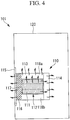
- FIG. 4 is a front view of a partial internal structure of an outdoor unit in a reference example.
- the outdoor unit 101 includes a control box (sheet metal) 120, in which electric components are stored and installed, and a reactor 110 installed inside the control box 120.
- the reactor 110 includes a coil 112 composed of a wound wire 111, a first core 113 incorporating the coil 112, a second core 114 facing the first core 113 and generating less heat than the first core 113, and a base plate 115.
- Fig. 3 is a front view of the reactor 110.
- a first core 113 is an E-core having an E-shape
- a second core 114 is an I-core having an I-shape.
- the first core 113 includes a center leg 117 at the center of a base 116.
- the center leg 117 is inserted and fitted in the coil 112.
- respective ends of the base 116 are provided with outer legs 118a, 118b that are parallel to the center leg 117 and slightly longer than the center leg 117.
- the first core 113 has a higher magnetic flux density due to the presence of the aforementioned air gap 119. This results in a higher loss density, making the first core 113 apt to increase its temperature.
- the base 116 is the most heat generating part in the first core 113 (the part indicated by cross-hatching in Fig. 4 ). To deal with this heat, as shown in Fig. 4 , the base 116 of the first core 113 is fixed to the base plate 115 by welding, and the base plate 115 is fixed inside the control box 120. This allows heat generated in the first core 113 to be transmitted to the base plate 115, then to the control box 120, and finally released out of the control box 120.
- the reactor 110 is an essential component for controller configuration, the reactor 110 is incorporated in a controller ASSY (assembly). To release heat generated in the first core 113 out of the control box 120, the reactor 110 is often implemented inside the control box 120 as shown in Fig. 4 . However, due to the base 116, which is the most heat generating part, being fixed to the base plate 115, there is a problem of deterioration of the fixing part caused by the influence of heat. Another problem is that heat generated in the wound wire 111 and other components stays inside the control box 120.
- An object of the present invention which has been made in view of the above circumstances, is to provide a reactor that can prevent deterioration of the fixing part.
- the present invention adopts the following solutions.
- the present invention provides a reactor including: a coil composed of a wound wire; a first core incorporating the coil; a second core facing the first core and generating less heat than the first core; and a base plate to which the second core is fixed.
- the reactor of the present invention has the second core with less heat generation fixed to the base plate.
- the first core with high heat generation is fixed to the base plate.
- fixing the first core to the base plate causes heat to be directly transmitted from the first core to the fixing part, which may deteriorate the fixing part.
- fixing the second core with less heat generation to the base plate as in the present invention causes heat to be hardly transmitted from the first core to the fixing part. This can prevent deterioration of the fixing part.
- the first core is preferably an E-core
- the second core is preferably an I-core
- the E-core When the first core is an E-core and the second core is an I-core, the E-core has a higher magnetic flux density due to an air gap between the center of the second core (I-core) and the first core (E-core). This results in a higher loss density, making the E-core apt to increase its temperature. Meanwhile, the reactor of the present embodiment has the I-core with less heat generation fixed to the base plate. Thus, heat from the E-core with relatively high heat generation is hardly transmitted to the fixing part, effectively preventing deterioration of the fixing part caused by heat from the E-core.
- the present invention further provides an outdoor unit including: a control box in which electric components are stored and installed; and the aforementioned reactor fixed to an outer surface of the control box via the base plate.
- the reactor is disposed outside of the control box.
- heat generated from the wound wire and other components of the reactor is less likely to stay inside the control box.
- the reactor is fixed to the outside of the control box via the base plate to which the second core is fixed. That is, the first core with high heat generation is located most distant from the control box. Accordingly, heat generated from the first core reaches the control box only after passing through the second core and the base plate, and as such the heat is hardly transmitted to the control box. This can minimize the effect of heat from the reactor on the control box, allowing for easy thermal design inside the control box.
- the first core with high heat generation is externally exposed, the first core can be cooled by air.
- the first core is preferably provided with a cooling mechanism.
- the cooling mechanism composed of a refrigerant pipe and the like being provided to the first core, heat dissipation capability of the first core (and the reactor as a whole) can be improved. This allows for downsizing the reactor.
- the reactor of the present invention has the second core with less heat generation fixed to the base plate. This causes heat from the first core to be hardly transmitted to the fixing part, preventing deterioration of the fixing part.
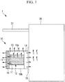
- Fig. 1 is a front view of a partial internal structure of an outdoor unit according to the present embodiment.
- the outdoor unit 1 includes a control box (sheet metal) 20 in which electric components are stored and installed, and a reactor 10 fixed to an outer surface of the control box 20. Further, a ceiling 21 is provided to an upper part of the control box 20 so as to cover the reactor 10.
- the reactor 10 includes a coil 12 composed of a wound wire 11, a first core 13 incorporating the coil 12, a second core 14 facing the first core 13 and generating less heat than the first core 13, and a base plate 15.
- the first core 13 is an E-core having an E-shape
- the second core 14 is an I-core having an I-shape
- the first core 13 includes a center leg 17 at the center of a base 16.
- the center leg 17 is inserted and fitted in the coil 12.
- respective ends of the base 16 are provided with outer legs 18a, 18b that are parallel to the center leg 17 and slightly longer than the center leg 17. Surfaces of the outer legs 18a, 18b facing the second core 14 make direct contact with the second core 14.
- a surface of the second core 14 facing the base plate 15 is fixed to the base plate 15 by welding, and the reactor 10 is fixed and installed onto an outer surface of the control box 20 via the base plate 15.
- the present embodiment provides the following functions and effects.
- the reactor 10 of the present embodiment has the second core 14, which generates less heat, fixed to the base plate 15.
- the first core 13, which generates more heat is fixed to the base plate 15.
- fixing the first core 13 to the base plate 15 causes heat to be directly transmitted from the first core 13 to the fixing part, which may deteriorate the fixing part.
- fixing the second core 14 with less heat generation to the base plate 15 as in the present embodiment causes heat to be hardly transmitted from the first core 13 to the fixing part. This can prevent deterioration of the fixing part.
- the E-core 13 has a higher magnetic flux density due to an air gap between the center of the second core (I-core) 14 and the first core (E-core) 13. This results in a higher loss density, making the E-core 13 apt to increase its temperature.
- the reactor 10 of the present embodiment has the I-core 14 with less heat generation fixed to the base plate 15.
- heat from the E-core 13 with relatively high heat generation is hardly transmitted to the fixing part, effectively preventing deterioration of the fixing part caused by heat from the E-core 13.
- the reactor 10 is disposed outside of the control box 20.
- heat generated from the wound wire 11 and other components of the reactor 10 is less likely to stay inside the control box 20.
- the reactor 10 is fixed to the outside of the control box 20 via the base plate 15 to which the second core 14 is fixed. That is, the first core 13 with high heat generation is located most distant from the control box 20. Accordingly, heat generated from the first core 13 reaches the control box 20 only after passing through the second core 14 and the base plate 15, and as such the heat is hardly transmitted to the control box 20 (refer to wavy arrows in Fig. 1 ). This can minimize the effect of heat from the reactor 10 on the control box 20, allowing for easy thermal design inside the control box 20. Moreover, since the first core 13 with high heat generation is externally exposed, the first core 13 can be cooled by air.
- the ceiling 21 is provided to the upper part of the control box 20 so as to cover the reactor 10 (in particular, one side of the outer leg 18a of the reactor 10).
- the ceiling 21 can receive rainwater falling from above, protecting the reactor 10 against water.
- Basic configurations of the present embodiment are basically the same as those of the first embodiment, and a difference from the first embodiment lies in that the base 16 of the first core 13 is provided with a cooling mechanism 22 in the present embodiment. Accordingly, in the present embodiment, an explanation will be given of this difference and other redundant explanations will be omitted.
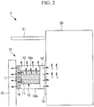
- Fig. 2 is a front view of a partial internal structure of an outdoor unit 1' according to the present embodiment.
- the base 16 of the first core 13 is provided with the cooling mechanism 22 on its surface opposite from that facing the control box 20.
- the cooling mechanism 22 is composed of a refrigerant pipe.
- the present embodiment provides the following functions and effects.
- cooling mechanism 22 composed of a refrigerant pipe and the like being provided to the first core 13 as described above, heat dissipation capability of the first core 13 (and the reactor 10 as a whole) can be improved. This allows for downsizing the reactor 10.
- the installing position of the cooling mechanism 22 is not limited to the base 16 of the first core 13 as described above; for example, the cooling mechanism 22 may be provided on the outer leg 18a or 18b of the first core 13.
- first core 13 as an E-core
- second core 14 as an I-core
- the shapes of the first core 13 and the second core 14 are not limited to these.
- the first core 13 and the second core 14 may be a U-core having a U-shape.
Landscapes
- Engineering & Computer Science (AREA)
- Power Engineering (AREA)
- Chemical & Material Sciences (AREA)
- Combustion & Propulsion (AREA)
- Mechanical Engineering (AREA)
- General Engineering & Computer Science (AREA)
- Transformer Cooling (AREA)
- Other Air-Conditioning Systems (AREA)
Abstract
Provided is a reactor that can prevent deterioration of a fixing part. The reactor (10) includes: a coil (12) composed of a wound wire (11); a first core (13) incorporating the coil (12); the second core (14) facing the first core (13) and generating less heat than the first core (13); and a base plate (15) to which the second core (14) is fixed. The first core (13) is an E-core, and the second core (14) is an I-core. Also, an outdoor unit 1 includes: a control box (20) in which electric components are stored and installed; and the reactor (10) fixed to an outer surface of the control box (20) via the base plate (15).
Description
- The present invention relates to a reactor that is used, for example, for an air conditioner, in particular a packaged air conditioner, and to an outdoor unit using the reactor.
- An outdoor unit of a conventional air conditioner includes a reactor disposed in an electric component module (e.g., see Patent Literature 1). The reactor used for such an outdoor unit is typically composed of cores and a wound wire, and the cores typically consist of an E-shaped core and an I-shaped core as disclosed in Patent Literature 2.
-
- [PTL 1]
Japanese Unexamined Patent Application, Publication No.2010-175224 - [PTL 2]
Japanese Unexamined Patent Application, Publication No.Hei 8-148353 2652525 - Heat generated from a reactor has been a conventional problem in disposing the reactor in a control box of an outdoor unit. Referring to
Figs. 3 to 5 , the problem of heat generated from the reactor will be explained in more detail.Fig. 4 is a front view of a partial internal structure of an outdoor unit in a reference example. Theoutdoor unit 101 includes a control box (sheet metal) 120, in which electric components are stored and installed, and areactor 110 installed inside thecontrol box 120. Thereactor 110 includes acoil 112 composed of awound wire 111, afirst core 113 incorporating thecoil 112, asecond core 114 facing thefirst core 113 and generating less heat than thefirst core 113, and abase plate 115. - Referring to
Fig. 3 , structures of thefirst core 113 and thesecond core 114 will be explained in more detail.Fig. 3 is a front view of thereactor 110. As shown inFig. 3 , in thereactor 110, afirst core 113 is an E-core having an E-shape, and asecond core 114 is an I-core having an I-shape. Thefirst core 113 includes acenter leg 117 at the center of abase 116. Thecenter leg 117 is inserted and fitted in thecoil 112. Further, respective ends of thebase 116 are provided withouter legs center leg 117 and slightly longer than thecenter leg 117. - Surfaces of the
outer legs second core 114 make direct contact with thesecond core 114, and anair gap 119 is formed in the center of thesecond core 114 with thefirst core 113. Also, a surface of thebase 116 facing thebase plate 115 is fixed to thebase plate 115 by welding. As shown inFig. 4 , thereactor 110 is fixed and installed inside thecontrol box 120 via thebase plate 115. - In this
outdoor unit 101, large current flows through thereactor 110, which causes thereactor 110 to generate heat (refer to wavy arrows inFig. 4 ). Also, comparing thefirst core 113 and thesecond core 114, thefirst core 113 has a higher magnetic flux density due to the presence of theaforementioned air gap 119. This results in a higher loss density, making thefirst core 113 apt to increase its temperature. In particular, thebase 116 is the most heat generating part in the first core 113 (the part indicated by cross-hatching inFig. 4 ). To deal with this heat, as shown inFig. 4 , thebase 116 of thefirst core 113 is fixed to thebase plate 115 by welding, and thebase plate 115 is fixed inside thecontrol box 120. This allows heat generated in thefirst core 113 to be transmitted to thebase plate 115, then to thecontrol box 120, and finally released out of thecontrol box 120. - Since the
reactor 110 is an essential component for controller configuration, thereactor 110 is incorporated in a controller ASSY (assembly). To release heat generated in thefirst core 113 out of thecontrol box 120, thereactor 110 is often implemented inside thecontrol box 120 as shown inFig. 4 . However, due to thebase 116, which is the most heat generating part, being fixed to thebase plate 115, there is a problem of deterioration of the fixing part caused by the influence of heat. Another problem is that heat generated in thewound wire 111 and other components stays inside thecontrol box 120. - In view of the above, a method is reported by which the
reactor 110 is fixed to an outer surface of thecontrol box 120 via thebase plate 115, like an outdoor unit 101' ofFig. 5 . However, even though thereactor 110 is installed on the outer surface of thecontrol box 120 as shown inFig. 5 , thebase 116 is still fixed to thebase plate 115. This causes heat generated in thefirst core 113 to be transmitted to the fixing part and the inside of thecontrol box 120. As such, no fundamental solutions to preventing deterioration of the fixing part have been reported to date. - An object of the present invention, which has been made in view of the above circumstances, is to provide a reactor that can prevent deterioration of the fixing part.
- To solve the above problem, the present invention adopts the following solutions.
- The present invention provides a reactor including: a coil composed of a wound wire; a first core incorporating the coil; a second core facing the first core and generating less heat than the first core; and a base plate to which the second core is fixed.
- The reactor of the present invention has the second core with less heat generation fixed to the base plate. Typically, the first core with high heat generation is fixed to the base plate. However, fixing the first core to the base plate causes heat to be directly transmitted from the first core to the fixing part, which may deteriorate the fixing part. In contrast, fixing the second core with less heat generation to the base plate as in the present invention causes heat to be hardly transmitted from the first core to the fixing part. This can prevent deterioration of the fixing part.
- In the reactor, the first core is preferably an E-core, and the second core is preferably an I-core.
- When the first core is an E-core and the second core is an I-core, the E-core has a higher magnetic flux density due to an air gap between the center of the second core (I-core) and the first core (E-core). This results in a higher loss density, making the E-core apt to increase its temperature. Meanwhile, the reactor of the present embodiment has the I-core with less heat generation fixed to the base plate. Thus, heat from the E-core with relatively high heat generation is hardly transmitted to the fixing part, effectively preventing deterioration of the fixing part caused by heat from the E-core.
- The present invention further provides an outdoor unit including: a control box in which electric components are stored and installed; and the aforementioned reactor fixed to an outer surface of the control box via the base plate.
- In the outdoor unit of the present invention, the reactor is disposed outside of the control box. Thus, heat generated from the wound wire and other components of the reactor is less likely to stay inside the control box. Further, the reactor is fixed to the outside of the control box via the base plate to which the second core is fixed. That is, the first core with high heat generation is located most distant from the control box. Accordingly, heat generated from the first core reaches the control box only after passing through the second core and the base plate, and as such the heat is hardly transmitted to the control box. This can minimize the effect of heat from the reactor on the control box, allowing for easy thermal design inside the control box. Moreover, since the first core with high heat generation is externally exposed, the first core can be cooled by air.
- In the outdoor unit, the first core is preferably provided with a cooling mechanism.
- With the cooling mechanism composed of a refrigerant pipe and the like being provided to the first core, heat dissipation capability of the first core (and the reactor as a whole) can be improved. This allows for downsizing the reactor.
- The reactor of the present invention has the second core with less heat generation fixed to the base plate. This causes heat from the first core to be hardly transmitted to the fixing part, preventing deterioration of the fixing part.
-
-
Fig. 1 is a front view of a partial internal structure of an outdoor unit according to a first embodiment of the present invention. -
Fig. 2 is a front view of a partial internal structure of an outdoor unit according to a second embodiment of the present invention. -
Fig. 3 is a front view of a reactor. -
Fig. 4 is a front view of a partial internal structure of an outdoor unit in a reference example. -
Fig. 5 is a front view of a partial internal structure of an outdoor unit in another reference example. - Hereinafter, embodiments of a reactor and an outdoor unit according to the present invention will be described with reference to the drawings.
- A first embodiment of the present invention will be described below with reference to
Fig. 1 . -
Fig. 1 is a front view of a partial internal structure of an outdoor unit according to the present embodiment. - As shown in
Fig. 1 , the outdoor unit 1 according to the present embodiment includes a control box (sheet metal) 20 in which electric components are stored and installed, and areactor 10 fixed to an outer surface of thecontrol box 20. Further, aceiling 21 is provided to an upper part of thecontrol box 20 so as to cover thereactor 10. Thereactor 10 includes acoil 12 composed of awound wire 11, afirst core 13 incorporating thecoil 12, asecond core 14 facing thefirst core 13 and generating less heat than thefirst core 13, and abase plate 15. - The
first core 13 is an E-core having an E-shape, and thesecond core 14 is an I-core having an I-shape. Thefirst core 13 includes acenter leg 17 at the center of abase 16. Thecenter leg 17 is inserted and fitted in thecoil 12. Further, respective ends of the base 16 are provided withouter legs center leg 17 and slightly longer than thecenter leg 17. Surfaces of theouter legs second core 14 make direct contact with thesecond core 14. - A surface of the
second core 14 facing thebase plate 15 is fixed to thebase plate 15 by welding, and thereactor 10 is fixed and installed onto an outer surface of thecontrol box 20 via thebase plate 15. - With the above configuration, the present embodiment provides the following functions and effects.
- As described above, the
reactor 10 of the present embodiment has thesecond core 14, which generates less heat, fixed to thebase plate 15. Typically, thefirst core 13, which generates more heat, is fixed to thebase plate 15. However, fixing thefirst core 13 to thebase plate 15 causes heat to be directly transmitted from thefirst core 13 to the fixing part, which may deteriorate the fixing part. In contrast, fixing thesecond core 14 with less heat generation to thebase plate 15 as in the present embodiment causes heat to be hardly transmitted from thefirst core 13 to the fixing part. This can prevent deterioration of the fixing part. - Also, when the
first core 13 is an E-core and thesecond core 14 is an I-core, the E-core 13 has a higher magnetic flux density due to an air gap between the center of the second core (I-core) 14 and the first core (E-core) 13. This results in a higher loss density, making the E-core 13 apt to increase its temperature. Meanwhile, thereactor 10 of the present embodiment has the I-core 14 with less heat generation fixed to thebase plate 15. Thus, heat from the E-core 13 with relatively high heat generation (in particular, from the base 16 indicated by cross-hatching inFig. 1 ) is hardly transmitted to the fixing part, effectively preventing deterioration of the fixing part caused by heat from the E-core 13. - In the outdoor unit 1 of the present embodiment, the
reactor 10 is disposed outside of thecontrol box 20. Thus, heat generated from thewound wire 11 and other components of thereactor 10 is less likely to stay inside thecontrol box 20. Further, thereactor 10 is fixed to the outside of thecontrol box 20 via thebase plate 15 to which thesecond core 14 is fixed. That is, thefirst core 13 with high heat generation is located most distant from thecontrol box 20. Accordingly, heat generated from thefirst core 13 reaches thecontrol box 20 only after passing through thesecond core 14 and thebase plate 15, and as such the heat is hardly transmitted to the control box 20 (refer to wavy arrows inFig. 1 ). This can minimize the effect of heat from thereactor 10 on thecontrol box 20, allowing for easy thermal design inside thecontrol box 20. Moreover, since thefirst core 13 with high heat generation is externally exposed, thefirst core 13 can be cooled by air. - In the outdoor unit 1 of the present embodiment, the
ceiling 21 is provided to the upper part of thecontrol box 20 so as to cover the reactor 10 (in particular, one side of theouter leg 18a of the reactor 10). During rainy weather, for example, theceiling 21 can receive rainwater falling from above, protecting thereactor 10 against water. - Next, a second embodiment of the present invention will be described with reference to
Fig. 2 . - Basic configurations of the present embodiment are basically the same as those of the first embodiment, and a difference from the first embodiment lies in that the
base 16 of thefirst core 13 is provided with acooling mechanism 22 in the present embodiment. Accordingly, in the present embodiment, an explanation will be given of this difference and other redundant explanations will be omitted. - The same components as those of the first embodiment are denoted by the same reference numerals and redundant explanations thereof will be omitted.
-
Fig. 2 is a front view of a partial internal structure of an outdoor unit 1' according to the present embodiment. As shown inFig. 2 , thebase 16 of thefirst core 13 is provided with thecooling mechanism 22 on its surface opposite from that facing thecontrol box 20. Thecooling mechanism 22 is composed of a refrigerant pipe. - With the above-described configuration, the present embodiment provides the following functions and effects.
- With the
cooling mechanism 22 composed of a refrigerant pipe and the like being provided to thefirst core 13 as described above, heat dissipation capability of the first core 13 (and thereactor 10 as a whole) can be improved. This allows for downsizing thereactor 10. - The installing position of the
cooling mechanism 22 is not limited to thebase 16 of thefirst core 13 as described above; for example, thecooling mechanism 22 may be provided on theouter leg first core 13. - Although the above two embodiments have exemplarily described the
first core 13 as an E-core and thesecond core 14 as an I-core, the shapes of thefirst core 13 and thesecond core 14 are not limited to these. For example, thefirst core 13 and thesecond core 14 may be a U-core having a U-shape. -
- 1, 1'
- Outdoor unit
- 10
- Reactor
- 11
- Wound wire
- 12
- Coil
- 13
- First core (E-core)
- 14
- Second core (I-core)
- 15
- Base plate
- 16
- Base
- 17
- Center leg
- 18a, 18b
- Outer leg
- 20
- Control box (sheet metal)
- 21
- Ceiling
- 22
- Cooling mechanism
Claims (4)
- A reactor (10) comprising:a coil (12) composed of a wound wire (11);a first core (13) incorporating the coil (12);a second core (14) facing the first core (13) and generating less heat than the first core (13); anda base plate (15) to which the second core (14) is fixed.
- The reactor according to claim 1, wherein the first core (13) is an E-core, and the second core (14) is an I-core.
- An outdoor unit (1) comprising:a control box (20) in which electric components are stored and installed; andthe reactor (10) of claim 1 or 2, the reactor (10) being fixed to an outer surface of the control box (20) via the base plate (15).
- The outdoor unit (1) according to claim 3, wherein the first core (13) is provided with a cooling mechanism (22).
Applications Claiming Priority (1)
| Application Number | Priority Date | Filing Date | Title |
|---|---|---|---|
| JP2018041820A JP7455499B2 (en) | 2018-03-08 | 2018-03-08 | Reactor and outdoor unit |
Publications (1)
| Publication Number | Publication Date |
|---|---|
| EP3537463A1 true EP3537463A1 (en) | 2019-09-11 |
Family
ID=65529354
Family Applications (1)
| Application Number | Title | Priority Date | Filing Date |
|---|---|---|---|
| EP19158218.8A Withdrawn EP3537463A1 (en) | 2018-03-08 | 2019-02-20 | Reactor and outdoor unit |
Country Status (2)
| Country | Link |
|---|---|
| EP (1) | EP3537463A1 (en) |
| JP (1) | JP7455499B2 (en) |
Citations (7)
| Publication number | Priority date | Publication date | Assignee | Title |
|---|---|---|---|---|
| JPH03218002A (en) * | 1990-01-23 | 1991-09-25 | Daikin Ind Ltd | Fixing method of reactor transformer |
| JPH08148353A (en) | 1994-11-22 | 1996-06-07 | Tamura Seisakusho Co Ltd | Reactor |
| JP2010175224A (en) | 2009-02-02 | 2010-08-12 | Daikin Ind Ltd | Air conditioning device |
| JP2013131540A (en) * | 2011-12-20 | 2013-07-04 | Tdk Corp | Core, transformer, choke coil, and switching power supply device |
| WO2017022023A1 (en) * | 2015-07-31 | 2017-02-09 | 三菱電機株式会社 | Outdoor unit for air conditioner |
| GB2549868A (en) * | 2015-02-13 | 2017-11-01 | Mitsubishi Electric Corp | Outdoor unit for air conditioning devices |
| AU2016316086A1 (en) * | 2015-08-28 | 2018-01-04 | Mitsubishi Heavy Industries Thermal Systems, Ltd. | Air conditioning device |
Family Cites Families (3)
| Publication number | Priority date | Publication date | Assignee | Title |
|---|---|---|---|---|
| JP2008121966A (en) * | 2006-11-10 | 2008-05-29 | Daikin Ind Ltd | Air conditioner outdoor unit |
| JP4935609B2 (en) * | 2007-10-02 | 2012-05-23 | ダイキン工業株式会社 | How to use the reactor |
| JP2016127109A (en) * | 2014-12-26 | 2016-07-11 | ダイキン工業株式会社 | Reactor cooling structure |
-
2018
- 2018-03-08 JP JP2018041820A patent/JP7455499B2/en active Active
-
2019
- 2019-02-20 EP EP19158218.8A patent/EP3537463A1/en not_active Withdrawn
Patent Citations (8)
| Publication number | Priority date | Publication date | Assignee | Title |
|---|---|---|---|---|
| JPH03218002A (en) * | 1990-01-23 | 1991-09-25 | Daikin Ind Ltd | Fixing method of reactor transformer |
| JPH08148353A (en) | 1994-11-22 | 1996-06-07 | Tamura Seisakusho Co Ltd | Reactor |
| JP2652525B2 (en) | 1994-11-22 | 1997-09-10 | 株式会社タムラ製作所 | Reactor |
| JP2010175224A (en) | 2009-02-02 | 2010-08-12 | Daikin Ind Ltd | Air conditioning device |
| JP2013131540A (en) * | 2011-12-20 | 2013-07-04 | Tdk Corp | Core, transformer, choke coil, and switching power supply device |
| GB2549868A (en) * | 2015-02-13 | 2017-11-01 | Mitsubishi Electric Corp | Outdoor unit for air conditioning devices |
| WO2017022023A1 (en) * | 2015-07-31 | 2017-02-09 | 三菱電機株式会社 | Outdoor unit for air conditioner |
| AU2016316086A1 (en) * | 2015-08-28 | 2018-01-04 | Mitsubishi Heavy Industries Thermal Systems, Ltd. | Air conditioning device |
Also Published As
| Publication number | Publication date |
|---|---|
| JP7455499B2 (en) | 2024-03-26 |
| JP2019160865A (en) | 2019-09-19 |
Similar Documents
| Publication | Publication Date | Title |
|---|---|---|
| JP6400663B2 (en) | Contactless power transformer | |
| JP6509472B2 (en) | Trance | |
| WO2017221804A1 (en) | Inductor and mounting structure of said inductor | |
| US20130293330A1 (en) | Magnetic device having thermally-conductive bobbin | |
| US11398335B2 (en) | Electromagnetic coil assembly for control rod driving mechanism and method of manufacturing the same | |
| JP4459982B2 (en) | Bushing and generator | |
| JP2014204487A (en) | Power source device | |
| JP7455499B2 (en) | Reactor and outdoor unit | |
| CN105405599A (en) | Easy-to-cool transformer | |
| JP2011014669A (en) | Cooling device for magnetic part | |
| RU103971U1 (en) | SINGLE-PHASE ELECTRIC INDUCTION DEVICE | |
| WO2019044835A1 (en) | Radiator with inductor | |
| CN117524681A (en) | Resonant leakage inductance transformer for plate-type ozone generator | |
| JP6505616B2 (en) | Stationary induction equipment | |
| JP2006294787A (en) | Reactor | |
| CN213242120U (en) | Saturable reactor suitable for direct current transmission engineering converter valve | |
| JP2008041929A (en) | Stationary induction electric appliance | |
| CN107240492A (en) | A kind of non-crystaline amorphous metal current transformer being easily assembled to | |
| CN223967099U (en) | Transformer and vehicle-mounted charger | |
| CN215643947U (en) | Anticollision oil-immersed power transformer | |
| JP2008218699A (en) | Reactor and air conditioner | |
| JP2020047721A (en) | Inductor installation structure | |
| CN209297869U (en) | A kind of efficiency level-one amorphous alloy iron core distribution transformer | |
| CN221812020U (en) | A transformer with good sealing structure | |
| JP6619195B2 (en) | Reactor |
Legal Events
| Date | Code | Title | Description |
|---|---|---|---|
| PUAI | Public reference made under article 153(3) epc to a published international application that has entered the european phase |
Free format text: ORIGINAL CODE: 0009012 |
|
| STAA | Information on the status of an ep patent application or granted ep patent |
Free format text: STATUS: THE APPLICATION HAS BEEN PUBLISHED |
|
| AK | Designated contracting states |
Kind code of ref document: A1 Designated state(s): AL AT BE BG CH CY CZ DE DK EE ES FI FR GB GR HR HU IE IS IT LI LT LU LV MC MK MT NL NO PL PT RO RS SE SI SK SM TR |
|
| AX | Request for extension of the european patent |
Extension state: BA ME |
|
| STAA | Information on the status of an ep patent application or granted ep patent |
Free format text: STATUS: THE APPLICATION IS DEEMED TO BE WITHDRAWN |
|
| 18D | Application deemed to be withdrawn |
Effective date: 20200312 |