EP3537430B1 - Verfahren und vorrichtung für eine kostengünstige unterdrückung von akustischer reifenhohlraumresonanz - Google Patents
Verfahren und vorrichtung für eine kostengünstige unterdrückung von akustischer reifenhohlraumresonanz Download PDFInfo
- Publication number
- EP3537430B1 EP3537430B1 EP19156808.8A EP19156808A EP3537430B1 EP 3537430 B1 EP3537430 B1 EP 3537430B1 EP 19156808 A EP19156808 A EP 19156808A EP 3537430 B1 EP3537430 B1 EP 3537430B1
- Authority
- EP
- European Patent Office
- Prior art keywords
- tire
- antinoise
- signal
- cavity resonance
- frequency
- Prior art date
- Legal status (The legal status is an assumption and is not a legal conclusion. Google has not performed a legal analysis and makes no representation as to the accuracy of the status listed.)
- Active
Links
Images




Classifications
-
- G—PHYSICS
- G10—MUSICAL INSTRUMENTS; ACOUSTICS
- G10K—SOUND-PRODUCING DEVICES; METHODS OR DEVICES FOR PROTECTING AGAINST, OR FOR DAMPING, NOISE OR OTHER ACOUSTIC WAVES IN GENERAL; ACOUSTICS NOT OTHERWISE PROVIDED FOR
- G10K11/00—Methods or devices for transmitting, conducting or directing sound in general; Methods or devices for protecting against, or for damping, noise or other acoustic waves in general
- G10K11/16—Methods or devices for protecting against, or for damping, noise or other acoustic waves in general
- G10K11/175—Methods or devices for protecting against, or for damping, noise or other acoustic waves in general using interference effects; Masking sound
- G10K11/178—Methods or devices for protecting against, or for damping, noise or other acoustic waves in general using interference effects; Masking sound by electro-acoustically regenerating the original acoustic waves in anti-phase
- G10K11/1787—General system configurations
- G10K11/17879—General system configurations using both a reference signal and an error signal
- G10K11/17883—General system configurations using both a reference signal and an error signal the reference signal being derived from a machine operating condition, e.g. engine RPM or vehicle speed
-
- B—PERFORMING OPERATIONS; TRANSPORTING
- B60—VEHICLES IN GENERAL
- B60C—VEHICLE TYRES; TYRE INFLATION; TYRE CHANGING; CONNECTING VALVES TO INFLATABLE ELASTIC BODIES IN GENERAL; DEVICES OR ARRANGEMENTS RELATED TO TYRES
- B60C23/00—Devices for measuring, signalling, controlling, or distributing tyre pressure or temperature, specially adapted for mounting on vehicles; Arrangement of tyre inflating devices on vehicles, e.g. of pumps or of tanks; Tyre cooling arrangements
- B60C23/06—Signalling devices actuated by deformation of the tyre, e.g. tyre mounted deformation sensors or indirect determination of tyre deformation based on wheel speed, wheel-centre to ground distance or inclination of wheel axle
- B60C23/061—Signalling devices actuated by deformation of the tyre, e.g. tyre mounted deformation sensors or indirect determination of tyre deformation based on wheel speed, wheel-centre to ground distance or inclination of wheel axle by monitoring wheel speed
- B60C23/062—Frequency spectrum analysis of wheel speed signals, e.g. using Fourier transformation
-
- G—PHYSICS
- G10—MUSICAL INSTRUMENTS; ACOUSTICS
- G10K—SOUND-PRODUCING DEVICES; METHODS OR DEVICES FOR PROTECTING AGAINST, OR FOR DAMPING, NOISE OR OTHER ACOUSTIC WAVES IN GENERAL; ACOUSTICS NOT OTHERWISE PROVIDED FOR
- G10K11/00—Methods or devices for transmitting, conducting or directing sound in general; Methods or devices for protecting against, or for damping, noise or other acoustic waves in general
- G10K11/16—Methods or devices for protecting against, or for damping, noise or other acoustic waves in general
- G10K11/172—Methods or devices for protecting against, or for damping, noise or other acoustic waves in general using resonance effects
-
- G—PHYSICS
- G10—MUSICAL INSTRUMENTS; ACOUSTICS
- G10K—SOUND-PRODUCING DEVICES; METHODS OR DEVICES FOR PROTECTING AGAINST, OR FOR DAMPING, NOISE OR OTHER ACOUSTIC WAVES IN GENERAL; ACOUSTICS NOT OTHERWISE PROVIDED FOR
- G10K11/00—Methods or devices for transmitting, conducting or directing sound in general; Methods or devices for protecting against, or for damping, noise or other acoustic waves in general
- G10K11/16—Methods or devices for protecting against, or for damping, noise or other acoustic waves in general
- G10K11/175—Methods or devices for protecting against, or for damping, noise or other acoustic waves in general using interference effects; Masking sound
- G10K11/178—Methods or devices for protecting against, or for damping, noise or other acoustic waves in general using interference effects; Masking sound by electro-acoustically regenerating the original acoustic waves in anti-phase
- G10K11/1781—Methods or devices for protecting against, or for damping, noise or other acoustic waves in general using interference effects; Masking sound by electro-acoustically regenerating the original acoustic waves in anti-phase characterised by the analysis of input or output signals, e.g. frequency range, modes, transfer functions
-
- G—PHYSICS
- G10—MUSICAL INSTRUMENTS; ACOUSTICS
- G10K—SOUND-PRODUCING DEVICES; METHODS OR DEVICES FOR PROTECTING AGAINST, OR FOR DAMPING, NOISE OR OTHER ACOUSTIC WAVES IN GENERAL; ACOUSTICS NOT OTHERWISE PROVIDED FOR
- G10K11/00—Methods or devices for transmitting, conducting or directing sound in general; Methods or devices for protecting against, or for damping, noise or other acoustic waves in general
- G10K11/16—Methods or devices for protecting against, or for damping, noise or other acoustic waves in general
- G10K11/175—Methods or devices for protecting against, or for damping, noise or other acoustic waves in general using interference effects; Masking sound
- G10K11/178—Methods or devices for protecting against, or for damping, noise or other acoustic waves in general using interference effects; Masking sound by electro-acoustically regenerating the original acoustic waves in anti-phase
- G10K11/1785—Methods, e.g. algorithms; Devices
-
- G—PHYSICS
- G10—MUSICAL INSTRUMENTS; ACOUSTICS
- G10K—SOUND-PRODUCING DEVICES; METHODS OR DEVICES FOR PROTECTING AGAINST, OR FOR DAMPING, NOISE OR OTHER ACOUSTIC WAVES IN GENERAL; ACOUSTICS NOT OTHERWISE PROVIDED FOR
- G10K11/00—Methods or devices for transmitting, conducting or directing sound in general; Methods or devices for protecting against, or for damping, noise or other acoustic waves in general
- G10K11/16—Methods or devices for protecting against, or for damping, noise or other acoustic waves in general
- G10K11/175—Methods or devices for protecting against, or for damping, noise or other acoustic waves in general using interference effects; Masking sound
- G10K11/178—Methods or devices for protecting against, or for damping, noise or other acoustic waves in general using interference effects; Masking sound by electro-acoustically regenerating the original acoustic waves in anti-phase
- G10K11/1785—Methods, e.g. algorithms; Devices
- G10K11/17853—Methods, e.g. algorithms; Devices of the filter
-
- G—PHYSICS
- G10—MUSICAL INSTRUMENTS; ACOUSTICS
- G10K—SOUND-PRODUCING DEVICES; METHODS OR DEVICES FOR PROTECTING AGAINST, OR FOR DAMPING, NOISE OR OTHER ACOUSTIC WAVES IN GENERAL; ACOUSTICS NOT OTHERWISE PROVIDED FOR
- G10K2210/00—Details of active noise control [ANC] covered by G10K11/178 but not provided for in any of its subgroups
- G10K2210/10—Applications
- G10K2210/12—Rooms, e.g. ANC inside a room, office, concert hall or automobile cabin
-
- G—PHYSICS
- G10—MUSICAL INSTRUMENTS; ACOUSTICS
- G10K—SOUND-PRODUCING DEVICES; METHODS OR DEVICES FOR PROTECTING AGAINST, OR FOR DAMPING, NOISE OR OTHER ACOUSTIC WAVES IN GENERAL; ACOUSTICS NOT OTHERWISE PROVIDED FOR
- G10K2210/00—Details of active noise control [ANC] covered by G10K11/178 but not provided for in any of its subgroups
- G10K2210/10—Applications
- G10K2210/128—Vehicles
- G10K2210/1282—Automobiles
-
- G—PHYSICS
- G10—MUSICAL INSTRUMENTS; ACOUSTICS
- G10K—SOUND-PRODUCING DEVICES; METHODS OR DEVICES FOR PROTECTING AGAINST, OR FOR DAMPING, NOISE OR OTHER ACOUSTIC WAVES IN GENERAL; ACOUSTICS NOT OTHERWISE PROVIDED FOR
- G10K2210/00—Details of active noise control [ANC] covered by G10K11/178 but not provided for in any of its subgroups
- G10K2210/10—Applications
- G10K2210/128—Vehicles
- G10K2210/1282—Automobiles
- G10K2210/12821—Rolling noise; Wind and body noise
-
- G—PHYSICS
- G10—MUSICAL INSTRUMENTS; ACOUSTICS
- G10K—SOUND-PRODUCING DEVICES; METHODS OR DEVICES FOR PROTECTING AGAINST, OR FOR DAMPING, NOISE OR OTHER ACOUSTIC WAVES IN GENERAL; ACOUSTICS NOT OTHERWISE PROVIDED FOR
- G10K2210/00—Details of active noise control [ANC] covered by G10K11/178 but not provided for in any of its subgroups
- G10K2210/10—Applications
- G10K2210/129—Vibration, e.g. instead of, or in addition to, acoustic noise
-
- G—PHYSICS
- G10—MUSICAL INSTRUMENTS; ACOUSTICS
- G10K—SOUND-PRODUCING DEVICES; METHODS OR DEVICES FOR PROTECTING AGAINST, OR FOR DAMPING, NOISE OR OTHER ACOUSTIC WAVES IN GENERAL; ACOUSTICS NOT OTHERWISE PROVIDED FOR
- G10K2210/00—Details of active noise control [ANC] covered by G10K11/178 but not provided for in any of its subgroups
- G10K2210/30—Means
- G10K2210/301—Computational
- G10K2210/3023—Estimation of noise, e.g. on error signals
- G10K2210/30232—Transfer functions, e.g. impulse response
-
- G—PHYSICS
- G10—MUSICAL INSTRUMENTS; ACOUSTICS
- G10K—SOUND-PRODUCING DEVICES; METHODS OR DEVICES FOR PROTECTING AGAINST, OR FOR DAMPING, NOISE OR OTHER ACOUSTIC WAVES IN GENERAL; ACOUSTICS NOT OTHERWISE PROVIDED FOR
- G10K2210/00—Details of active noise control [ANC] covered by G10K11/178 but not provided for in any of its subgroups
- G10K2210/30—Means
- G10K2210/301—Computational
- G10K2210/3032—Harmonics or sub-harmonics
-
- G—PHYSICS
- G10—MUSICAL INSTRUMENTS; ACOUSTICS
- G10K—SOUND-PRODUCING DEVICES; METHODS OR DEVICES FOR PROTECTING AGAINST, OR FOR DAMPING, NOISE OR OTHER ACOUSTIC WAVES IN GENERAL; ACOUSTICS NOT OTHERWISE PROVIDED FOR
- G10K2210/00—Details of active noise control [ANC] covered by G10K11/178 but not provided for in any of its subgroups
- G10K2210/50—Miscellaneous
- G10K2210/511—Narrow band, e.g. implementations for single frequency cancellation
Definitions
- aspects of the disclosure generally relate to acoustic tire cavity resonance cancellation.
- Road noise cancellation (RNC) technology reduces unwanted, typically broadband, road noise inside a vehicle by generating antinoise, i.e., sound waves that are substantially opposite in phase and identical in magnitude to the in-cabin road noise, in a similar manner to other active noise control (ANC) technologies.
- RNC technology uses vibration sensors to pick up unwanted structural vibrations generated by the interaction of the tires and the road surface that lead to unwanted noise in the passenger cabin. Tire cavity resonance is a significant contributor to this unwanted noise. The result of cancelling such road noise is a more pleasurable ride, and it enables vehicle manufacturers to use lightweight materials, thereby increasing fuel mileage and reducing emissions.
- EOC Engine order cancellation
- a non-acoustic signal such as a revolutions-per-minute (RPM) sensor, that generates a signal representative of the engine speed as a reference.
- RPM revolutions-per-minute
- This reference signal is used to generate sound waves that are opposite in phase to the engine noise audible in the vehicle interior. Because EOC systems use data from an RPM sensor, EOC systems do not require accelerometers.
- Publication EP 2 133 866 A1 discloses a narrow band ANC system for reducing a noise signal from a vehicle engine based on the engine RPM.
- Publication US 5 325 437 A discloses another system for reducing noises in a vehicle.
- Further ANC systems for reducing road noise are disclosed in publication Nikos Zafeiropoulos et al.: "Active Control of Structure-Borne Road Noise Based on the Separation of Front and Rear Structural Road Noise Related Dynamics", SAE International Journal of Passenger Cars - Mechanical Systems, vol. 8, no. 3, 15 May 2015 , and in publication Jie Duan: "Active Control of Vehicle Powertrain and Road Noise", 1 June 2011 .
- Publication US 2013/0136270 A1 discloses an active vibration noise control apparatus.
- the active vibration noise control apparatus refers to a vehicle speed versus frequency correspondence table representing a correspondence relation between a vehicle speed of a vehicle and a frequency of a reference signal, and changes the frequency of the reference signal that is used by an adaptive notch filter.
- a vehicle speed versus frequency correspondence table representing a correspondence relation between a vehicle speed of a vehicle and a frequency of a reference signal, and changes the frequency of the reference signal that is used by an adaptive notch filter.
- FIG. 1 illustrates an example diagram 100 of an automobile tire 102 rolling over a surface 104.
- the tire 102 rolls over the surface 104 (e.g ., pavement)
- the tire 102 generates audible sound.
- Some of the sound is generated due to the impact of the tire tread with the road texture.
- Tonal sound is caused by deformation of the tire 102 as it rolls, which excites the internal acoustic cavity resonance or resonances of the tire 102, which in turn imparts a mechanical vibration into the wheel hub and shaft. If the tire 102 is unloaded, it is fully round and there is only one internal resonance frequency and one mode shape.
- the unloaded degenerate mode splits into a lower and higher frequency mode, which have resonance frequencies referred to herein as Fl and Fh.
- Fl and Fh resonance frequencies
- FIG. 2 illustrates an example graph 200 of in-vehicle noise level as a function of frequency. Because tires 102 on passenger automobiles typically fall within a small range of diameters ( e.g., near 16"), these resonance frequencies are near 225 Hz and typically fall between 190 Hz and 250 Hz. An example of the noise generated by the interaction of the tire with the pavement is shown in the graph 200, which is a plot of sound pressure level (SPL) in the passenger cabin, at the location of a passenger's ears.
- SPL sound pressure level
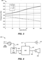
- FIG. 3 illustrates an example graph 300 of tire 102 TCR frequencies as a function of vehicle speed.
- tire 102 Fh cavity resonance shifts very slightly upward with increasing vehicle speed, while Fl shifts very slightly downward with increasing vehicle speed.
- tire 102 cavity resonance frequency is largely independent of inflation pressure, and so is largely independent of ambient temperature.
- This graph is exemplary in nature and note that not all vehicles exhibit this exact behavior of frequency shift with changes in speed.
- RNC systems generally cancel or reduce unwanted noise by generating cancellation sound waves to destructively interfere with the unwanted audible noise.
- the frequency and amplitude of the cancellation sound waves are, for the most part, identical to those of the noise, but the phase differs by 180 degrees in relation to the noise. In ideal situations, this method fully cancels the unwanted noise at a listening location or locations.
- Destructive interference results when noise and largely identical magnitude but opposite phase antinoise reduces the sound pressure level at a location. This effect of targeted reduction of the sound pressure level of an undesirable noise with the use of antinoise played over speakers is called active noise cancellation (ANC).
- ANC active noise cancellation
- the unwanted noise can be caused by the engine, the interaction of the tires 102 and the road surface 104, and/or sound radiated by the vibration of other parts of the vehicle and, therefore, varies with the speed, road conditions, and operating states of the vehicle.
- accelerometers used as input vibration sensors may be disposed around the vehicle to monitor the structural behavior of the suspension and chassis components.
- RNC systems often utilize a broadband feed-forward Least Mean Squares (LMS) ANC framework in order to generate antinoise by adaptively filtering the signal from the vibration sensor or sensors to generate an antinoise signals that play though speakers in order to cancel the road noise.
- Vibration sensors may include acceleration sensors such as accelerometers, or may be force gauges, load cells, strain gauges, geophones, linear variable differential transformers, etc.
- an accelerometer is a device whose output voltage is proportional to acceleration. Single and multi-axis accelerometers are available.
- An example RNC system may use six two-axis accelerometers deployed around a vehicle on various vibrating suspension parts, in addition to four microphone error sensors deployed in the passenger cabin, in combination with an LMS ANC system requiring a large number of million-instructions-per-second (MIPS) of computational power.
- MIPS million-instructions-per-second
- EOC technology uses a non-acoustic signal such as an RPM signal representative of the engine speed as a reference in order to generate sound that is opposite in phase to the engine noise audible in the vehicle interior.
- RPM signal representative of the engine speed
- Common EOC systems utilize a narrowband feed-forward ANC framework to generate antinoise using an RPM signal to guide the generation of an engine order identical in frequency to engine order to be cancelled, and adaptively filtering it to create an antinoise signal.
- the antinoise After being transmitted via a secondary path from an antinoise source to a listening position, the antinoise ideally has the same amplitude, but opposite phase, as the combined sound generated by the engine and exhaust pipes and filtered by the primary paths that extend from the engine to the listening position and from the exhaust pipe outlet to the listening position.
- a non-acoustic sensor for example an RPM sensor
- RPM sensors may be, for example, Hall Effect sensors which are placed adjacent to a spinning steel disk.
- Other detection principles can be employed, such as optical sensors or inductive sensors.
- the signal from the RPM sensor can be used as a guiding signal for generating an arbitrary number of reference engine order signals corresponding to each of the engine orders.
- the reference engine orders form the basis for noise cancelling signals generated by the one or more narrowband adaptive feed-forward LMS blocks that form the EOC system.
- EOC systems are guided by data from an RPM sensor, most EOC systems do not require accelerometers or direct acoustic measurement of the engine order sound at the location of the engine. As EOC systems require only an input RPM signal, one or more interior cabin microphones, and a LMS ANC system, EOC systems require fewer MIPS as compared to RNC systems. Additionally, as compared to RNC systems, EOC systems do not require any accelerometers. Typical cancellation depth of low frequency engine orders by EOC systems is far better than RNC systems. EOC systems cancel on the order of ⁇ 20 dB of low frequency engine orders, while 10 dB of higher frequency orders is achievable.
- RNC systems are typically designed to cancel broadband signals, while EOC systems are designed and optimized to cancel narrowband signals, such as individual sine tones. TCR noise is more accurately described as the latter, e.g., as a single tone or a combination of two tones.
- a modified EOC algorithm may be utilized to cancel sound due to the TCR.
- the system may utilize an additional or alternate RPM signal or signals (such as that of the axle of any of the tires), and a lookup table of wheel RPM vs. TCR frequency or frequencies.
- FIG. 4 illustrates an example TCR noise control system 400.
- the system includes an RPM sensor 401 which provides a square-wave signal indicative of rotation of the drive shaft or of an axle of the vehicle to which a tire is connected. As the TCR frequency or frequencies are directly or indirectly proportional to tire speed, the RPM signal is representative of the frequencies produced by the tire.
- the RPM sensor 401 is used in conjunction with a lookup table of RPM vs. frequency or frequencies 405.
- the frequency supplied to an ANC filter 407 (which is often termed W-filter in LMS systems) which provides a filtered signal 408 to a loudspeaker 409.
- the ANC filter 407 may have a fixed or adaptive transfer function and may be adapted by a feedback system or a feedforward system or a combination thereof.
- an error microphone or microphones 410 may be employed, which pick up the residual noise at or near the listening position(s) and provides an error signal(s) 411 representative of the residual noise for use in optimizing the ANC filter 407.
- EOC systems will include multiple of one or more of these components. Implementation of these slightly more complex systems are straightforward for those skilled in the art.
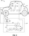
- FIG. 5 illustrates a single-channel, feedforward, TCR noise cancellation system with an adaptive LMS algorithm.
- the road noise originating from the interaction of the pavement surface and wheel 502 is mechanically and/or acoustically transferred via a primary path to an error microphone 505 according to a transfer characteristic P(z).
- a TCR noise cancellation system includes an RPM sensor 514 which is mounted to an axle 515 of the vehicle 504. Alternately, this RPM sensor 514 can be mounted on other rotating shafts whose rotational rate is indicative of the rotational rate of one or more tires.
- the rotational speed of the tire correlates with the audible TCR noise within the vehicle cabin because the frequency or frequencies of the tire cavity resonances change in a deterministic way with tire RPM, detected by RPM sensor 514.
- the RPM signal x1(n) may be a square-wave signal having the frequency of the tire rotation, though one may have to adjust this signal slightly as often 2 of the 60 pulses per revolution are missing.
- the RPM signal x1(n) is used in conjunction with a lookup table 516 of RPM vs frequency or frequencies to provide estimated frequencies of the tire cavity noise. Further aspects of the lookup table 516 are described with reference to FIG. 6 .
- error microphone 505 which may be arranged within the cabin in a headrest 506 of a seat ( e.g., the driver's seat). Alternate locations for this microphone include the headliner of the vehicle, on the top of a seat back, or in other in-cabin locations that may be generally near passengers' ears. Although one microphone is shown in FIG 5 , typically systems for EOC or RNC include multiple error microphones.
- a transfer characteristic W(z) of a controllable filter 508 is controlled by adaptive filter controller 509 which may be an LMS based algorithm that adapts based on the error signal e(n) and on the signal x2(n) filtered with a transfer characteristic S'(z) by a filter 510.
- S'(z) is a measurement of S(z)
- S(z) represents the transfer function between the loudspeaker 511 and the microphone 505, i.e., the transfer function of a secondary path.
- Antinoise signal y(n) that, after having travelled through the secondary path, ideally has a waveform inverse in phase to that of the TCR noise audible within the cabin, near error microphone 505, is generated by an adaptive filter formed by controllable filter 508 and filter controller 509, based on the identified transfer characteristic W(z) and the signal x2(n).
- Antinoise signal y(n) is played through loudspeaker 511, and, after it has travelled through the secondary path, creates sound with a waveform substantially opposite in phase and similar in magnitude to that of the TCR noise audible near the error microphone 505. The superposition of the antinoise with the noise audible in the cabin thereby reduces the TCR noise within the cabin, near microphone 505.
- the exemplary system shown in FIG. 5 employs a straightforward single-channel feedforward LMS control system 507, but other control structures, e.g., multi-channel systems with a multiplicity of additional channels, a multiplicity of additional microphones 512, and a multiplicity of additional loudspeakers 513, may be applied as well.
- L loudspeakers and M microphones may be employed.
- the number of microphone input channels into filter controller 509 is M
- the number of output channels from filters 508 is L
- the number of channels between filter 510 and filter control 509 is L ⁇ M.
- multiple RPM reference sensors 514 can be input into RPM vs. frequency or frequencies lookup table 516, thereby possibly creating more W(z) filters, and a more complex signal x2(n).
- FIG. 6 illustrates an example TCR cancellation tuning table 600.
- the example table 600 lists frequencies of each TCR for a given RPM. In the illustrated example, two frequencies are given, for both low and high frequency tire cavity resonances. These low and high frequencies correspond to the loaded tire lower and higher frequency modes Fl and Fh. While not shown, in another example a single center frequency between the low and high frequency modes may be used.
- the LMS algorithm takes as an input the RPM, and generates a sine wave for each order based on this lookup table 600. The LMS algorithm then adaptively adjusts the amplitude and phase of each sine wave by applying W-Filter 508 to achieve the minimum error pressure at the location of the microphone error sensors.
- the relevant RPM for the table 600 is axle rotation RPM of the axle of the tire 102.
- a conversion factor has translated km/h into RPM for an example tire 102.
- the table 600 may be utilized with a conversion factor that the circumference of a 195/65 R15 tire is 78.4 inches, and that there are 39370.1 inches per kilometer.
- FIG. 7 illustrates an example schematic for a single TCR frequency noise cancellation system 700.
- an RPM sensor 701 is used to provide a signal indicative of a rotational speed of the tire 102 or axle. This signal is processed via a lookup table 702 mapping rotational speed to TCR frequency.
- a frequency generator 703 synthesizes a sine wave at a frequency F according to the estimated frequency of the TCR identified via the lookup table 702.
- a transfer characteristic S'(z) indicated at 705 represents a transfer function of a secondary path between a loudspeaker 707 and a microphone 708.
- a transfer characteristic W(z) shown at 704 of a controllable filter is controlled by a LMS-based algorithm 706 that adapts based on an error signal e(n) received from the error microphone 708 and on the frequency signal filtered at 705 by the transfer characteristic S'(z).
- FIG. 8 illustrates an example schematic for a dual TCR frequency noise cancellation system 800. Similar to the system 700, in the TCR noise cancellation system 800 an RPM sensor 801 is used to provide a signal indicative of a rotational speed of the tire 102 or axle. However, instead of being used to provide a single resonance frequency, in the system 800 the signal is processed via a lookup table 802 to provide estimated low and high frequency resonances of the tire noise. These low and high frequencies correspond to the loaded tire lower and higher frequency modes Fl and Fh.
- a first frequency generator 803 synthesizes the resonance frequency Fl according to the estimated low frequency of the tire noise identified via the lookup table 802, while a second frequency generator 803' synthesizes the resonance frequency Fh according to the estimated high frequency of the tire noise identified via the lookup table 802.
- Transfer characteristics S'(z) indicated at 805 and 805' each represent a transfer function of the secondary path between a loudspeaker 807 and a microphone 808.
- a transfer characteristic W(z) shown at 804 of a controllable filter is controlled by a LMS-based algorithm 806 that adapts processing of resonance frequency Fl based on an error signal e(n) received from the error microphone 808 and on the frequency signal filtered at 805 with the transfer characteristic S'(z) of 805.
- a second transfer characteristic W(z) shown at 804' is controlled by a LMS-based algorithm 806' that adapts processing of resonance frequency Fh based on the error signal e(n) received from the error microphone 808 and on the frequency signal filtered at 805' with the transfer characteristic S'(z) of 805'.
- the outputs of the transfer characteristic W(z) 804 and the transfer characteristic W(z) 804' are combined at adder 809. This combined output of the adder 809 is played though speaker 807 to create sound with a waveform substantially opposite in phase and similar in magnitude to that of the TCR noise audible near microphone 808.
- FIG. 9 illustrates an example schematic for a dual TCR frequency and broadband RNC noise cancellation system 900. Similar to the system 800, the noise cancellation system 900 utilizes the elements 901-909 consistent with operation of elements 801-809 discussed above. Additionally, the system 900 further includes an acceleration sensor 910. A sense signal output by acceleration sensor 910 is utilized by a broadband feed-forward ANC framework to generate antinoise by adaptively filtering the signal from acceleration sensor 910 to generate antinoise. A transfer characteristic S'(z) indicated at 912 also represents a transfer function of a secondary path between a loudspeaker 907 and a microphone 908.
- a transfer characteristic W(z) shown at 911 of a controllable filter is controlled by a LMS-based algorithm 913 to adapt based on an error signal e(n) received from the error microphone 708 and on the accelerometer signal filtered at 912 by the transfer characteristic S'(z).
- a LMS-based algorithm 913 to adapt based on an error signal e(n) received from the error microphone 708 and on the accelerometer signal filtered at 912 by the transfer characteristic S'(z).
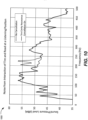
- FIG. 10 illustrates an example graph 1000 of tire cavity noise cancellation depth achieved through use of TCR cancellation.
- the trace with TCR noise cancellation active (or on) achieves 6-10 dB of noise cancellation in the region of tire noise, e.g., from around 190-250 Hz.
- FIG. 11 illustrates an example TCR and road noise control method 1100, as may be performed by one of the systems shown above.
- the system infers a rotational speed of a tire of the vehicle.
- the system synthesizes frequencies of a TCR of the tire, using a frequency generator, according to the rotational speed of the tire, to generate a sense signal or signals.
- the system performs adaptive filtering on the sense signal or signals, e.g., according to the LMS algorithm, to generate a summed antinoise signal from the sense signal or signals.
- the system converts the antinoise signal derived from the active noise control filtering into antinoise, e.g., by way of a loudspeaker, which is radiated to a listening position in an interior of the vehicle.
- the antinoise signal is configured so that the antinoise reduces the TCR noise at the error microphone, which is likely near a listening position.
- the system picks up an error signal at or close to the listening position, e.g., by way of a microphone.
- the system filters the sense signal or signals with a filter or filters that models the path between loudspeaker and microphone used to control the LMS algorithm of the adaptive ANC filtering.
- the lookup table 600 is dynamically adapted over time to improve the accuracy of the frequency estimate at each wheel RPM.
- This dynamic adaptation may be a complete replacement of this table, or may be a refinement of one more values in this table. This adaptation may occur once, or it may be more frequent. This could improve ideal cancellation for the system if a different tire/wheel size is substituted on the vehicle after its manufacture date.
- the dynamic adaptation is performed using a microphone to search for center frequencies of any relatively high Q peaks, for example between approximately 180 and 260 Hz.
- the frequency generator and frequency data in the lookup table 600 could be replaced by one or more actual sensors (e.g ., including a tracking filter) whose filtered output signals create a sense signal or signals containing the one or two TCR frequencies Fl and Fh.
- the sensor could be an accelerometer, microphone, or other vibration sensor as previously discussed.
- An alternate non claimed example that does not use an RPM sensor could simply include a tracking filter or filters on a sensor output to find the TCR peak or peaks between 180 and 250 Hz. Other methods and techniques of applying filters to a signal in order to determine the highest amplitude peaks are possible.
- the TCR is the one peak or two peaks with the highest amplitudes in this frequency region.
- This sensor could be an accelerometer mounted on the wheel hub, control arms, chassis, vehicle interior, etc.
- This sensor could be a microphone that could be mounted near the tire, in the wheel well for example. Alternately, the microphone could be mounted at nearly any location in the passenger cabin, if the sole goal is to determine the TCR frequency or frequencies.
- Preferred locations include, but are not limited to, the headliner above a passenger's head, in seat backs, in head rests, etc.
- the TCR frequency or frequencies can be extracted, and a lookup table can be constructed vs. vehicle speed.
- the data in an existing lookup table of RPM or speed vs. TCR frequency or frequencies can be refined using data from the aforementioned filtered sensor output technique.
- the frequency data from this lookup table can be used by a frequency generator in the manner outlined in other embodiments.
- the filtered signal or signals can be used directly as the sense signal or signals, in the aforementioned manner.
- An alternate non claimed example can solve the problem of the TCR having a slightly low Q resonance.
- the filtered signal will not have sufficient bandwidth in frequency to cancel the entire frequency range of the TCR.
- Active noise control filter or filters will generate antinoise signal or signals from these sense signal or signals, and a loudspeaker will convert them into antinoise to reduce the noise due to the tire cavity resonance at a listening position. This method may be undertaken with either or both Fh and Fl to reduce the noise due to the TCR at a listening position.
- wheel RPM determines the wheel RPM. This includes knowledge of the drive shaft RPM and appropriate gear ratios.
- An alternate method to infer wheel RPM is knowledge of the wheel size and the speed of the vehicle derived from controller area network (CAN) messages of GPS data, etc. It is possible to construct a lookup table of wheel diameter vs. RPM vs. TCR frequency vs. speed. Then, using sensors such as machine vision, or data available on the CAN bus, the appropriate frequency data can be retrieved by the system with input from any or some of these alternate sensors.
- CAN controller area network
- Computing devices described herein generally include computer-executable instructions where the instructions may be executable by one or more computing devices such as those listed above.
- Computer-executable instructions may be compiled or interpreted from computer programs created using a variety of programming languages and/or technologies, including, without limitation, and either alone or in combination, Java TM , C, C++, C#, Visual Basic, JavaScript, Python, JavaScript, Perl, PL/SQL, etc.
- a processor e.g., a microprocessor
- receives instructions e.g., from a memory, a computer-readable medium, etc., and executes these instructions, thereby performing one or more processes, including one or more of the processes described herein.
- Such instructions and other data may be stored and transmitted using a variety of computer-readable media.
Landscapes
- Physics & Mathematics (AREA)
- Engineering & Computer Science (AREA)
- Acoustics & Sound (AREA)
- Multimedia (AREA)
- Mathematical Physics (AREA)
- Mechanical Engineering (AREA)
- Soundproofing, Sound Blocking, And Sound Damping (AREA)
- Fittings On The Vehicle Exterior For Carrying Loads, And Devices For Holding Or Mounting Articles (AREA)
Claims (10)
- Reifenhohlraumresonanz(TCR)-Geräuschunterdrückungssystem (700; 800; 900), umfassend:einen Sensor (701; 801; 901), der dazu konfiguriert ist, eine Drehzahl eines Reifens (102) eines Fahrzeugs zu erschließen;einen Frequenzgenerator (703; 803; 903), der dazu konfiguriert ist, eine Frequenz zu synthetisieren, die einer Reifenhohlraumresonanz entsprechend der Drehzahl des Reifens (102) entspricht, um ein Erfassungssignal zu erzeugen, wobei der Frequenzgenerator (703; 803; 903) dazu konfiguriert ist, eine Nachschlagetabelle (702; 802; 902) zur Unterdrückung von Reifenhohlraumresonanz zu verwenden, um die Frequenz zu identifizieren, die einer Reifenhohlraumresonanz entsprechend der Drehzahl des Reifens entspricht;die Nachschlagetabelle (702; 802; 902) zur Unterdrückung von Reifenhohlraumresonanz, die Reifenhohlraumresonanzfrequenzen den Drehzahlen des Reifens zuordnet;ein aktives Geräuschunterdrückungsfilter (704; 804; 904), das dazu konfiguriert ist, aus dem Erfassungssignal ein Gegengeräuschsignal zu erzeugen; undeinen Lautsprecher (707; 807; 907), der dazu konfiguriert ist, das Gegengeräuschsignal in Gegengeräusche umzuwandeln und die Gegengeräusche an eine Hörposition abzustrahlen,wobei das Gegengeräuschsignal so konfiguriert ist, dass die Gegengeräusche Geräusche aufgrund der Reifenhohlraumresonanz an der Hörposition reduzieren;dadurch gekennzeichnet, dassdas TCR-Geräuschunterdrückungssystem (700; 800; 900) ferner Folgendes umfasst:ein Mikrofon, das dazu konfiguriert ist, ein Audiosignal auszugeben, das auf von dem Reifen (102) ausgehende Geräusche hindeutet; undeinen Prozessor, der dazu konfiguriert ist, das Audiosignal zu empfangen, eine Mittenfrequenz eines Peaks mit hohem Q zu identifizieren, der einer Reifenhohlraumresonanzfrequenz entspricht, und die Nachschlagetabelle zur Unterdrückung von Reifenhohlraumresonanz (702; 802; 902) entsprechend der Mittenfrequenz und der erschlossenen Drehzahl des Reifens dynamisch anzupassen.
- TCR-Geräuschunterdrückungssystem (800; 900) nach Anspruch 1, ferner umfassend:einen zweiten Frequenzgenerator (803'; 903'), der dazu konfiguriert ist, eine zweite Frequenz zu synthetisieren, die einer zweiten Reifenhohlraumresonanz entsprechend der Drehzahl des Reifens (102) entspricht, um ein zweites Erfassungssignal zu erzeugen; undein zweites aktives Geräuschunterdrückungsfilter, das dazu konfiguriert ist, aus dem zweiten Erfassungssignal ein zweites Gegengeräuschsignal zu erzeugen,wobei der Lautsprecher (807; 907) ferner dazu konfiguriert ist, das zweite Gegengeräuschsignal in zweite Gegengeräusche umzuwandeln und die zweiten Gegengeräusche an die Hörposition abzustrahlen, so dass die zweiten Gegengeräusche Geräusche aufgrund der zweiten Reifenhohlraumresonanz an der Hörposition reduzieren.
- TCR-Geräuschunterdrückungssystem (800; 900) nach Anspruch 2, wobei die der Reifenhohlraumresonanz entsprechende Frequenz eine erste Reifenmodusresonanzfrequenz beinhaltet und die zweite Frequenz, die der zweiten Reifenhohlraumresonanz entspricht, eine zweite Reifenmodusresonanzfrequenz beinhaltet.
- TCR-Geräuschunterdrückungssystem nach Anspruch 1, ferner umfassend einen zweiten Lautsprecher, der dazu konfiguriert ist, das Gegengeräuschsignal in Gegengeräusche umzuwandeln und die Gegengeräusche an eine zweite Hörposition abzustrahlen, wobei das Gegengeräuschsignal so konfiguriert ist, dass die Gegengeräusche Geräusche aufgrund der Reifenhohlraumresonanz an der zweiten Hörposition reduzieren.
- TCR-Geräuschunterdrückungssystem (700; 800; 900) nach Anspruch 1, wobei der aktive Geräuschunterdrückungsfilter Folgendes umfasst:einen steuerbaren Filter (704; 804; 904); undeine Filtersteuerung, die dazu konfiguriert ist, den steuerbaren Filter (704; 804; 904) zu steuern.
- TCR-Geräuschunterdrückungssystem (700; 800; 900) nach Anspruch 5, ferner umfassend ein Mikrofon (708; 808; 908), das in einem Innenraum des Fahrzeugs angeordnet und dazu konfiguriert ist, ein Mikrofonsignal bereitzustellen, wobei der aktive Geräuschunterdrückungsfilter ferner dazu konfiguriert ist, den steuerbaren Filter (704; 804; 904) außerdem entsprechend dem Mikrofonsignal zu steuern.
- TCR-Geräuschunterdrückungssystem (700; 800; 900) nach Anspruch 1, wobei der aktive Geräuschunterdrückungsfilter dazu konfiguriert ist, den steuerbaren Filter (704; 804; 904) gemäß einem Algorithmus der kleinsten Quadrate (LMS) (706; 806; 906) zu steuern.
- Reifenhohlraumresonanz(TCR)-Geräuschunterdrückungsverfahren (1100), umfassend:Erschließen (1101) einer Drehzahl eines Reifens (102) eines Fahrzeugs unter Verwendung eines Sensors (701; 801; 901);Synthetisieren (1102) einer Frequenz einer Reifenhohlraumresonanz des Reifens (102) entsprechend der Drehzahl des Reifens (102) unter Verwendung eines Frequenzgenerators (703; 803; 903), um ein Erfassungssignal zu erzeugen;Verwenden einer Nachschlagetabelle (702; 802; 902) zur Unterdrückung von Reifenhohlraumresonanz durch den Frequenzgenerator (703; 803; 903), um die Frequenz zu identifizieren, die einer Reifenhohlraumresonanz entsprechend der Drehzahl des Reifens entspricht, wobei die Nachschlagetabelle (702; 802; 902) zur Unterdrückung von Reifenhohlraumresonanz die Reifenhohlraumresonanzfrequenzen den Drehzahlen des Reifens zuordnet;Erzeugen (1103) eines Gegengeräuschsignals aus dem Erfassungssignal unter Verwendung eines aktiven Geräuschunterdrückungsfilters; undUmwandeln (1104) des von dem aktiven Geräuschunterdrückungsfilter bereitgestellten Gegengeräuschsignals durch einen Lautsprecher (707; 807; 907) in Gegengeräusche und Abstrahlen der Gegengeräusche an eine Hörposition,wobei das Gegengeräuschsignal so konfiguriert ist, dass die Gegengeräusche Geräusche aufgrund der Reifenhohlraumresonanz an der Hörposition reduzieren;dadurch gekennzeichnet, dassdas TCR-Geräuschunterdrückungsverfahren (1100) ferner Folgendes umfasst:Empfangen eines Audiosignals von einem Mikrofon, das auf von dem Reifen (102) ausgehende Reifenhohlraumresonanzgeräusche hindeutet;Identifizieren einer Mittenfrequenz eines Peaks mit hohem Q, die einer Reifenhohlraumresonanzfrequenz entspricht, durch einen Prozessor; unddynamisches Anpassen der Nachschlagetabelle (702; 802; 902) zur Unterdrückung von Reifenhohlraumresonanz entsprechend der Mittenfrequenz und der erschlossenen Drehzahl des Reifens (102).
- TCR-Geräuschunterdrückungsverfahren (1100) nach Anspruch 8, ferner umfassend:Synthetisieren einer zweiten Frequenz der Reifenhohlraumresonanz des Reifens (102) entsprechend der Drehzahl des Reifens (102) unter Verwendung eines zweiten Frequenzgenerators (803'; 903'), um ein zweites Erfassungssignal zu erzeugen;Erzeugen eines zweiten Gegengeräuschsignals aus dem zweiten Erfassungssignal unter Verwendung eines zweiten aktiven Geräuschkontrollfilters; undUmwandeln (1104) des von dem zweiten aktiven Geräuschunterdrückungsfilter bereitgestellten zweiten Gegengeräuschsignals durch einen Lautsprecher (707; 807; 907) in Gegengeräusche und Abstrahlen der Gegengeräusche an die Hörposition.
- TCR-Geräuschunterdrückungsverfahren (1100) nach Anspruch 8, ferner umfassend:Bereitstellen (1105) eines Mikrofonsignals von einem Mikrofon (708; 808; 908), das in einem Innenraum des Fahrzeugs angeordnet ist;weiteres Steuern des aktiven Geräuschunterdrückungsfilters entsprechend dem Mikrofonsignal; undSteuern (1106) eines steuerbaren Filters (704; 804; 904) des aktiven Geräuschunterdrückungsfilter gemäß einem Algorithmus der kleinsten Quadrate (LMS) (706; 806; 906).
Applications Claiming Priority (1)
| Application Number | Priority Date | Filing Date | Title |
|---|---|---|---|
| US15/911,553 US11198337B2 (en) | 2018-03-05 | 2018-03-05 | Method and apparatus for a low cost, acoustic tire cavity resonance cancellation |
Publications (2)
| Publication Number | Publication Date |
|---|---|
| EP3537430A1 EP3537430A1 (de) | 2019-09-11 |
| EP3537430B1 true EP3537430B1 (de) | 2023-08-16 |
Family
ID=65433527
Family Applications (1)
| Application Number | Title | Priority Date | Filing Date |
|---|---|---|---|
| EP19156808.8A Active EP3537430B1 (de) | 2018-03-05 | 2019-02-13 | Verfahren und vorrichtung für eine kostengünstige unterdrückung von akustischer reifenhohlraumresonanz |
Country Status (3)
| Country | Link |
|---|---|
| US (1) | US11198337B2 (de) |
| EP (1) | EP3537430B1 (de) |
| CN (1) | CN110232906B (de) |
Families Citing this family (13)
| Publication number | Priority date | Publication date | Assignee | Title |
|---|---|---|---|---|
| US10891936B2 (en) * | 2019-06-05 | 2021-01-12 | Harman International Industries, Incorporated | Voice echo suppression in engine order cancellation systems |
| US10741162B1 (en) * | 2019-07-02 | 2020-08-11 | Harman International Industries, Incorporated | Stored secondary path accuracy verification for vehicle-based active noise control systems |
| DE102020200457A1 (de) * | 2020-01-15 | 2021-07-15 | Zf Friedrichshafen Ag | Schallminimierung an einem Fahrzeug |
| JP7520989B2 (ja) * | 2020-02-25 | 2024-07-23 | ボーズ・コーポレーション | 狭帯域の除去 |
| EP3979236B1 (de) * | 2020-09-30 | 2025-12-17 | Bridgestone Europe NV/SA | System zur aktiven geräuschunterdrückung und verfahren zur aussengeräuschreduzierung |
| CN112361404B (zh) * | 2020-10-27 | 2022-05-17 | 宁波方太厨具有限公司 | 油烟机降噪方法、降噪系统及应用有该降噪系统的油烟机 |
| US11417306B2 (en) | 2020-12-31 | 2022-08-16 | Bose Corporation | Systems and methods for engine harmonic cancellation |
| JP7554680B2 (ja) * | 2021-01-27 | 2024-09-20 | 株式会社マキタ | 電動作業機および電動作業機によって生じる騒音を制御する方法 |
| US11741937B1 (en) * | 2022-03-01 | 2023-08-29 | Harman International Industries, Incorporated | Active noise cancellation system secondary path adjustment |
| KR20230161134A (ko) * | 2022-05-18 | 2023-11-27 | 현대모비스 주식회사 | 가속도 신호 예측 장치 및 방법 |
| CN115438424A (zh) * | 2022-08-29 | 2022-12-06 | 奇瑞汽车股份有限公司 | 汽车车轮nvh匹配方法 |
| US11990112B2 (en) | 2022-10-21 | 2024-05-21 | Harman International Industries, Incorporated | Apparatus, system and/or method for acoustic road noise peak frequency cancellation |
| WO2025126732A1 (ja) * | 2023-12-13 | 2025-06-19 | 株式会社ブリヂストン | 情報処理装置及びその制御方法、並びに、プログラム |
Citations (2)
| Publication number | Priority date | Publication date | Assignee | Title |
|---|---|---|---|---|
| JP2005106728A (ja) * | 2003-10-01 | 2005-04-21 | Honda Motor Co Ltd | 路面状態検出装置 |
| US20130136270A1 (en) * | 2011-11-29 | 2013-05-30 | Honda Motor Co., Ltd. | Active vibration noise control apparatus |
Family Cites Families (8)
| Publication number | Priority date | Publication date | Assignee | Title |
|---|---|---|---|---|
| JP2921232B2 (ja) | 1991-12-27 | 1999-07-19 | 日産自動車株式会社 | 能動型不快波制御装置 |
| US5596141A (en) * | 1994-08-04 | 1997-01-21 | Nippondenso Co., Ltd. | Tire resonance frequency detecting system having inter-wheel noise elimination and method for the same |
| DE19723516C1 (de) * | 1997-06-05 | 1998-10-29 | Continental Ag | Anordnung und Verfahren zur aktiven Reduzierung von Reifenschwingungen |
| US7613529B1 (en) * | 2000-09-09 | 2009-11-03 | Harman International Industries, Limited | System for eliminating acoustic feedback |
| EP2133866B1 (de) | 2008-06-13 | 2016-02-17 | Harman Becker Automotive Systems GmbH | Adaptives Geräuschdämpfungssystem |
| US9494279B2 (en) * | 2014-10-21 | 2016-11-15 | Toyota Motor Engineering & Manufacturing North America, Inc. | Vehicle oil pan with active noise reduction control |
| US9706288B2 (en) * | 2015-03-12 | 2017-07-11 | Apple Inc. | Apparatus and method of active noise cancellation in a personal listening device |
| EP3226581B1 (de) * | 2016-03-31 | 2020-06-10 | Harman Becker Automotive Systems GmbH | Automatische geräuschkontrolle für einen fahrzeugsitz |
-
2018
- 2018-03-05 US US15/911,553 patent/US11198337B2/en active Active
-
2019
- 2019-02-13 EP EP19156808.8A patent/EP3537430B1/de active Active
- 2019-03-01 CN CN201910155032.1A patent/CN110232906B/zh active Active
Patent Citations (2)
| Publication number | Priority date | Publication date | Assignee | Title |
|---|---|---|---|---|
| JP2005106728A (ja) * | 2003-10-01 | 2005-04-21 | Honda Motor Co Ltd | 路面状態検出装置 |
| US20130136270A1 (en) * | 2011-11-29 | 2013-05-30 | Honda Motor Co., Ltd. | Active vibration noise control apparatus |
Non-Patent Citations (3)
| Title |
|---|
| JIE DUAN: "Active Control of Vehicle Powertrain and Road Noise", 1 June 2011 (2011-06-01), XP055318694, Retrieved from the Internet <URL:https://etd.ohiolink.edu/rws_etd/document/get/ucin1312479913/inline> [retrieved on 20161111] * |
| MOHAMED ZAMRI ET AL: "A survey of wheel tyre cavity resonance noise", INTERNATIONAL JOURNAL OF VEHICLE NOISE AND VIBRATION, vol. 9, no. 3/4, 1 January 2013 (2013-01-01), United Kingdom, pages 276, XP055775671, ISSN: 1479-1471, Retrieved from the Internet <URL:http://dx.doi.org/10.1504/IJVNV.2013.055811> DOI: 10.1504/IJVNV.2013.055811 * |
| NIKOS ZAFEIROPOULOS ET AL: "Active Control of Structure-Borne Road Noise Based on the Separation of Front and Rear Structural Road Noise Related Dynamics", SAE INTERNATIONAL JOURNAL OF PASSENGER CARS - MECHANICAL SYSTEMS, vol. 8, no. 3, 15 May 2015 (2015-05-15), US, XP055318548, ISSN: 1946-4002, DOI: 10.4271/2015-01-2222 * |
Also Published As
| Publication number | Publication date |
|---|---|
| EP3537430A1 (de) | 2019-09-11 |
| CN110232906B (zh) | 2024-10-29 |
| US20190270350A1 (en) | 2019-09-05 |
| US11198337B2 (en) | 2021-12-14 |
| CN110232906A (zh) | 2019-09-13 |
Similar Documents
| Publication | Publication Date | Title |
|---|---|---|
| EP3537430B1 (de) | Verfahren und vorrichtung für eine kostengünstige unterdrückung von akustischer reifenhohlraumresonanz | |
| CN108140376B (zh) | 发动机阶次和道路噪声控制 | |
| US11183166B1 (en) | Virtual location noise signal estimation for engine order cancellation | |
| US11335317B2 (en) | Road and engine noise control | |
| CN102159426B (zh) | 有源噪声控制装置 | |
| JP7662305B2 (ja) | 運転モード最適化エンジン次数キャンセル | |
| CN102097094A (zh) | 有源降噪装置 | |
| EP4148725B1 (de) | Adaptive aktive rauschunterdrückung auf basis von kopfbewegung | |
| Zafeiropoulos et al. | Active control of structure-borne road noise based on the separation of front and rear structural road noise related dynamics | |
| EP4298627A1 (de) | Instabilitätserkennung und adaptive anpassung für ein aktives rauschunterdrückungssystem | |
| CN116704990B (zh) | 主动噪声消除系统次级路径调整 | |
| CN116959397A (zh) | 快速自适应高频远程传声器噪声消除 |
Legal Events
| Date | Code | Title | Description |
|---|---|---|---|
| PUAI | Public reference made under article 153(3) epc to a published international application that has entered the european phase |
Free format text: ORIGINAL CODE: 0009012 |
|
| STAA | Information on the status of an ep patent application or granted ep patent |
Free format text: STATUS: THE APPLICATION HAS BEEN PUBLISHED |
|
| AK | Designated contracting states |
Kind code of ref document: A1 Designated state(s): AL AT BE BG CH CY CZ DE DK EE ES FI FR GB GR HR HU IE IS IT LI LT LU LV MC MK MT NL NO PL PT RO RS SE SI SK SM TR |
|
| AX | Request for extension of the european patent |
Extension state: BA ME |
|
| STAA | Information on the status of an ep patent application or granted ep patent |
Free format text: STATUS: REQUEST FOR EXAMINATION WAS MADE |
|
| 17P | Request for examination filed |
Effective date: 20200310 |
|
| RBV | Designated contracting states (corrected) |
Designated state(s): AL AT BE BG CH CY CZ DE DK EE ES FI FR GB GR HR HU IE IS IT LI LT LU LV MC MK MT NL NO PL PT RO RS SE SI SK SM TR |
|
| STAA | Information on the status of an ep patent application or granted ep patent |
Free format text: STATUS: EXAMINATION IS IN PROGRESS |
|
| 17Q | First examination report despatched |
Effective date: 20210219 |
|
| GRAP | Despatch of communication of intention to grant a patent |
Free format text: ORIGINAL CODE: EPIDOSNIGR1 |
|
| STAA | Information on the status of an ep patent application or granted ep patent |
Free format text: STATUS: GRANT OF PATENT IS INTENDED |
|
| INTG | Intention to grant announced |
Effective date: 20230330 |
|
| GRAS | Grant fee paid |
Free format text: ORIGINAL CODE: EPIDOSNIGR3 |
|
| P01 | Opt-out of the competence of the unified patent court (upc) registered |
Effective date: 20230527 |
|
| GRAA | (expected) grant |
Free format text: ORIGINAL CODE: 0009210 |
|
| STAA | Information on the status of an ep patent application or granted ep patent |
Free format text: STATUS: THE PATENT HAS BEEN GRANTED |
|
| AK | Designated contracting states |
Kind code of ref document: B1 Designated state(s): AL AT BE BG CH CY CZ DE DK EE ES FI FR GB GR HR HU IE IS IT LI LT LU LV MC MK MT NL NO PL PT RO RS SE SI SK SM TR |
|
| REG | Reference to a national code |
Ref country code: CH Ref legal event code: EP |
|
| REG | Reference to a national code |
Ref country code: DE Ref legal event code: R096 Ref document number: 602019034926 Country of ref document: DE |
|
| REG | Reference to a national code |
Ref country code: IE Ref legal event code: FG4D |
|
| REG | Reference to a national code |
Ref country code: LT Ref legal event code: MG9D |
|
| REG | Reference to a national code |
Ref country code: NL Ref legal event code: MP Effective date: 20230816 |
|
| REG | Reference to a national code |
Ref country code: AT Ref legal event code: MK05 Ref document number: 1600875 Country of ref document: AT Kind code of ref document: T Effective date: 20230816 |
|
| PG25 | Lapsed in a contracting state [announced via postgrant information from national office to epo] |
Ref country code: GR Free format text: LAPSE BECAUSE OF FAILURE TO SUBMIT A TRANSLATION OF THE DESCRIPTION OR TO PAY THE FEE WITHIN THE PRESCRIBED TIME-LIMIT Effective date: 20231117 |
|
| PG25 | Lapsed in a contracting state [announced via postgrant information from national office to epo] |
Ref country code: IS Free format text: LAPSE BECAUSE OF FAILURE TO SUBMIT A TRANSLATION OF THE DESCRIPTION OR TO PAY THE FEE WITHIN THE PRESCRIBED TIME-LIMIT Effective date: 20231216 |
|
| PG25 | Lapsed in a contracting state [announced via postgrant information from national office to epo] |
Ref country code: SE Free format text: LAPSE BECAUSE OF FAILURE TO SUBMIT A TRANSLATION OF THE DESCRIPTION OR TO PAY THE FEE WITHIN THE PRESCRIBED TIME-LIMIT Effective date: 20230816 Ref country code: RS Free format text: LAPSE BECAUSE OF FAILURE TO SUBMIT A TRANSLATION OF THE DESCRIPTION OR TO PAY THE FEE WITHIN THE PRESCRIBED TIME-LIMIT Effective date: 20230816 Ref country code: PT Free format text: LAPSE BECAUSE OF FAILURE TO SUBMIT A TRANSLATION OF THE DESCRIPTION OR TO PAY THE FEE WITHIN THE PRESCRIBED TIME-LIMIT Effective date: 20231218 Ref country code: NO Free format text: LAPSE BECAUSE OF FAILURE TO SUBMIT A TRANSLATION OF THE DESCRIPTION OR TO PAY THE FEE WITHIN THE PRESCRIBED TIME-LIMIT Effective date: 20231116 Ref country code: NL Free format text: LAPSE BECAUSE OF FAILURE TO SUBMIT A TRANSLATION OF THE DESCRIPTION OR TO PAY THE FEE WITHIN THE PRESCRIBED TIME-LIMIT Effective date: 20230816 Ref country code: LV Free format text: LAPSE BECAUSE OF FAILURE TO SUBMIT A TRANSLATION OF THE DESCRIPTION OR TO PAY THE FEE WITHIN THE PRESCRIBED TIME-LIMIT Effective date: 20230816 Ref country code: LT Free format text: LAPSE BECAUSE OF FAILURE TO SUBMIT A TRANSLATION OF THE DESCRIPTION OR TO PAY THE FEE WITHIN THE PRESCRIBED TIME-LIMIT Effective date: 20230816 Ref country code: IS Free format text: LAPSE BECAUSE OF FAILURE TO SUBMIT A TRANSLATION OF THE DESCRIPTION OR TO PAY THE FEE WITHIN THE PRESCRIBED TIME-LIMIT Effective date: 20231216 Ref country code: HR Free format text: LAPSE BECAUSE OF FAILURE TO SUBMIT A TRANSLATION OF THE DESCRIPTION OR TO PAY THE FEE WITHIN THE PRESCRIBED TIME-LIMIT Effective date: 20230816 Ref country code: GR Free format text: LAPSE BECAUSE OF FAILURE TO SUBMIT A TRANSLATION OF THE DESCRIPTION OR TO PAY THE FEE WITHIN THE PRESCRIBED TIME-LIMIT Effective date: 20231117 Ref country code: FI Free format text: LAPSE BECAUSE OF FAILURE TO SUBMIT A TRANSLATION OF THE DESCRIPTION OR TO PAY THE FEE WITHIN THE PRESCRIBED TIME-LIMIT Effective date: 20230816 Ref country code: AT Free format text: LAPSE BECAUSE OF FAILURE TO SUBMIT A TRANSLATION OF THE DESCRIPTION OR TO PAY THE FEE WITHIN THE PRESCRIBED TIME-LIMIT Effective date: 20230816 |
|
| PG25 | Lapsed in a contracting state [announced via postgrant information from national office to epo] |
Ref country code: PL Free format text: LAPSE BECAUSE OF FAILURE TO SUBMIT A TRANSLATION OF THE DESCRIPTION OR TO PAY THE FEE WITHIN THE PRESCRIBED TIME-LIMIT Effective date: 20230816 |
|
| PG25 | Lapsed in a contracting state [announced via postgrant information from national office to epo] |
Ref country code: ES Free format text: LAPSE BECAUSE OF FAILURE TO SUBMIT A TRANSLATION OF THE DESCRIPTION OR TO PAY THE FEE WITHIN THE PRESCRIBED TIME-LIMIT Effective date: 20230816 |
|
| PG25 | Lapsed in a contracting state [announced via postgrant information from national office to epo] |
Ref country code: SM Free format text: LAPSE BECAUSE OF FAILURE TO SUBMIT A TRANSLATION OF THE DESCRIPTION OR TO PAY THE FEE WITHIN THE PRESCRIBED TIME-LIMIT Effective date: 20230816 Ref country code: RO Free format text: LAPSE BECAUSE OF FAILURE TO SUBMIT A TRANSLATION OF THE DESCRIPTION OR TO PAY THE FEE WITHIN THE PRESCRIBED TIME-LIMIT Effective date: 20230816 Ref country code: ES Free format text: LAPSE BECAUSE OF FAILURE TO SUBMIT A TRANSLATION OF THE DESCRIPTION OR TO PAY THE FEE WITHIN THE PRESCRIBED TIME-LIMIT Effective date: 20230816 Ref country code: EE Free format text: LAPSE BECAUSE OF FAILURE TO SUBMIT A TRANSLATION OF THE DESCRIPTION OR TO PAY THE FEE WITHIN THE PRESCRIBED TIME-LIMIT Effective date: 20230816 Ref country code: DK Free format text: LAPSE BECAUSE OF FAILURE TO SUBMIT A TRANSLATION OF THE DESCRIPTION OR TO PAY THE FEE WITHIN THE PRESCRIBED TIME-LIMIT Effective date: 20230816 Ref country code: CZ Free format text: LAPSE BECAUSE OF FAILURE TO SUBMIT A TRANSLATION OF THE DESCRIPTION OR TO PAY THE FEE WITHIN THE PRESCRIBED TIME-LIMIT Effective date: 20230816 Ref country code: SK Free format text: LAPSE BECAUSE OF FAILURE TO SUBMIT A TRANSLATION OF THE DESCRIPTION OR TO PAY THE FEE WITHIN THE PRESCRIBED TIME-LIMIT Effective date: 20230816 |
|
| REG | Reference to a national code |
Ref country code: DE Ref legal event code: R097 Ref document number: 602019034926 Country of ref document: DE |
|
| PLBE | No opposition filed within time limit |
Free format text: ORIGINAL CODE: 0009261 |
|
| STAA | Information on the status of an ep patent application or granted ep patent |
Free format text: STATUS: NO OPPOSITION FILED WITHIN TIME LIMIT |
|
| 26N | No opposition filed |
Effective date: 20240517 |
|
| PG25 | Lapsed in a contracting state [announced via postgrant information from national office to epo] |
Ref country code: IT Free format text: LAPSE BECAUSE OF FAILURE TO SUBMIT A TRANSLATION OF THE DESCRIPTION OR TO PAY THE FEE WITHIN THE PRESCRIBED TIME-LIMIT Effective date: 20230816 Ref country code: SI Free format text: LAPSE BECAUSE OF FAILURE TO SUBMIT A TRANSLATION OF THE DESCRIPTION OR TO PAY THE FEE WITHIN THE PRESCRIBED TIME-LIMIT Effective date: 20230816 |
|
| PG25 | Lapsed in a contracting state [announced via postgrant information from national office to epo] |
Ref country code: MC Free format text: LAPSE BECAUSE OF FAILURE TO SUBMIT A TRANSLATION OF THE DESCRIPTION OR TO PAY THE FEE WITHIN THE PRESCRIBED TIME-LIMIT Effective date: 20230816 |
|
| REG | Reference to a national code |
Ref country code: CH Ref legal event code: PL |
|
| PG25 | Lapsed in a contracting state [announced via postgrant information from national office to epo] |
Ref country code: LU Free format text: LAPSE BECAUSE OF NON-PAYMENT OF DUE FEES Effective date: 20240213 |
|
| PG25 | Lapsed in a contracting state [announced via postgrant information from national office to epo] |
Ref country code: CH Free format text: LAPSE BECAUSE OF NON-PAYMENT OF DUE FEES Effective date: 20240229 |
|
| PG25 | Lapsed in a contracting state [announced via postgrant information from national office to epo] |
Ref country code: LU Free format text: LAPSE BECAUSE OF NON-PAYMENT OF DUE FEES Effective date: 20240213 Ref country code: CH Free format text: LAPSE BECAUSE OF NON-PAYMENT OF DUE FEES Effective date: 20240229 |
|
| PG25 | Lapsed in a contracting state [announced via postgrant information from national office to epo] |
Ref country code: BG Free format text: LAPSE BECAUSE OF FAILURE TO SUBMIT A TRANSLATION OF THE DESCRIPTION OR TO PAY THE FEE WITHIN THE PRESCRIBED TIME-LIMIT Effective date: 20230816 |
|
| PG25 | Lapsed in a contracting state [announced via postgrant information from national office to epo] |
Ref country code: BG Free format text: LAPSE BECAUSE OF FAILURE TO SUBMIT A TRANSLATION OF THE DESCRIPTION OR TO PAY THE FEE WITHIN THE PRESCRIBED TIME-LIMIT Effective date: 20230816 |
|
| REG | Reference to a national code |
Ref country code: BE Ref legal event code: MM Effective date: 20240229 |
|
| PG25 | Lapsed in a contracting state [announced via postgrant information from national office to epo] |
Ref country code: BE Free format text: LAPSE BECAUSE OF NON-PAYMENT OF DUE FEES Effective date: 20240229 |
|
| PG25 | Lapsed in a contracting state [announced via postgrant information from national office to epo] |
Ref country code: FR Free format text: LAPSE BECAUSE OF NON-PAYMENT OF DUE FEES Effective date: 20240229 |
|
| PG25 | Lapsed in a contracting state [announced via postgrant information from national office to epo] |
Ref country code: IE Free format text: LAPSE BECAUSE OF NON-PAYMENT OF DUE FEES Effective date: 20240213 |
|
| PG25 | Lapsed in a contracting state [announced via postgrant information from national office to epo] |
Ref country code: IE Free format text: LAPSE BECAUSE OF NON-PAYMENT OF DUE FEES Effective date: 20240213 Ref country code: FR Free format text: LAPSE BECAUSE OF NON-PAYMENT OF DUE FEES Effective date: 20240229 Ref country code: BE Free format text: LAPSE BECAUSE OF NON-PAYMENT OF DUE FEES Effective date: 20240229 |
|
| PG25 | Lapsed in a contracting state [announced via postgrant information from national office to epo] |
Ref country code: CY Free format text: LAPSE BECAUSE OF FAILURE TO SUBMIT A TRANSLATION OF THE DESCRIPTION OR TO PAY THE FEE WITHIN THE PRESCRIBED TIME-LIMIT; INVALID AB INITIO Effective date: 20190213 |
|
| PG25 | Lapsed in a contracting state [announced via postgrant information from national office to epo] |
Ref country code: HU Free format text: LAPSE BECAUSE OF FAILURE TO SUBMIT A TRANSLATION OF THE DESCRIPTION OR TO PAY THE FEE WITHIN THE PRESCRIBED TIME-LIMIT; INVALID AB INITIO Effective date: 20190213 |
|
| PG25 | Lapsed in a contracting state [announced via postgrant information from national office to epo] |
Ref country code: TR Free format text: LAPSE BECAUSE OF FAILURE TO SUBMIT A TRANSLATION OF THE DESCRIPTION OR TO PAY THE FEE WITHIN THE PRESCRIBED TIME-LIMIT Effective date: 20230816 |
|
| PGFP | Annual fee paid to national office [announced via postgrant information from national office to epo] |
Ref country code: GB Payment date: 20260121 Year of fee payment: 8 |
|
| PGFP | Annual fee paid to national office [announced via postgrant information from national office to epo] |
Ref country code: DE Payment date: 20260121 Year of fee payment: 8 |