EP3537033A1 - Vehicular luminaire, vehicular lamp, and method for manufacturing vehicular luminaire - Google Patents
Vehicular luminaire, vehicular lamp, and method for manufacturing vehicular luminaire Download PDFInfo
- Publication number
- EP3537033A1 EP3537033A1 EP19150959.5A EP19150959A EP3537033A1 EP 3537033 A1 EP3537033 A1 EP 3537033A1 EP 19150959 A EP19150959 A EP 19150959A EP 3537033 A1 EP3537033 A1 EP 3537033A1
- Authority
- EP
- European Patent Office
- Prior art keywords
- substrate
- power
- light
- luminaire
- socket
- Prior art date
- Legal status (The legal status is an assumption and is not a legal conclusion. Google has not performed a legal analysis and makes no representation as to the accuracy of the status listed.)
- Granted
Links
Images



Classifications
-
- F—MECHANICAL ENGINEERING; LIGHTING; HEATING; WEAPONS; BLASTING
- F21—LIGHTING
- F21S—NON-PORTABLE LIGHTING DEVICES; SYSTEMS THEREOF; VEHICLE LIGHTING DEVICES SPECIALLY ADAPTED FOR VEHICLE EXTERIORS
- F21S43/00—Signalling devices specially adapted for vehicle exteriors, e.g. brake lamps, direction indicator lights or reversing lights
- F21S43/10—Signalling devices specially adapted for vehicle exteriors, e.g. brake lamps, direction indicator lights or reversing lights characterised by the light source
- F21S43/13—Signalling devices specially adapted for vehicle exteriors, e.g. brake lamps, direction indicator lights or reversing lights characterised by the light source characterised by the type of light source
- F21S43/14—Light emitting diodes [LED]
-
- F—MECHANICAL ENGINEERING; LIGHTING; HEATING; WEAPONS; BLASTING
- F21—LIGHTING
- F21S—NON-PORTABLE LIGHTING DEVICES; SYSTEMS THEREOF; VEHICLE LIGHTING DEVICES SPECIALLY ADAPTED FOR VEHICLE EXTERIORS
- F21S43/00—Signalling devices specially adapted for vehicle exteriors, e.g. brake lamps, direction indicator lights or reversing lights
- F21S43/10—Signalling devices specially adapted for vehicle exteriors, e.g. brake lamps, direction indicator lights or reversing lights characterised by the light source
- F21S43/19—Attachment of light sources or lamp holders
- F21S43/195—Details of lamp holders, terminals or connectors
-
- F—MECHANICAL ENGINEERING; LIGHTING; HEATING; WEAPONS; BLASTING
- F21—LIGHTING
- F21S—NON-PORTABLE LIGHTING DEVICES; SYSTEMS THEREOF; VEHICLE LIGHTING DEVICES SPECIALLY ADAPTED FOR VEHICLE EXTERIORS
- F21S45/00—Arrangements within vehicle lighting devices specially adapted for vehicle exteriors, for purposes other than emission or distribution of light
- F21S45/40—Cooling of lighting devices
- F21S45/47—Passive cooling, e.g. using fins, thermal conductive elements or openings
- F21S45/48—Passive cooling, e.g. using fins, thermal conductive elements or openings with means for conducting heat from the inside to the outside of the lighting devices, e.g. with fins on the outer surface of the lighting device
-
- F—MECHANICAL ENGINEERING; LIGHTING; HEATING; WEAPONS; BLASTING
- F21—LIGHTING
- F21S—NON-PORTABLE LIGHTING DEVICES; SYSTEMS THEREOF; VEHICLE LIGHTING DEVICES SPECIALLY ADAPTED FOR VEHICLE EXTERIORS
- F21S45/00—Arrangements within vehicle lighting devices specially adapted for vehicle exteriors, for purposes other than emission or distribution of light
- F21S45/40—Cooling of lighting devices
- F21S45/49—Attachment of the cooling means
-
- F—MECHANICAL ENGINEERING; LIGHTING; HEATING; WEAPONS; BLASTING
- F21—LIGHTING
- F21V—FUNCTIONAL FEATURES OR DETAILS OF LIGHTING DEVICES OR SYSTEMS THEREOF; STRUCTURAL COMBINATIONS OF LIGHTING DEVICES WITH OTHER ARTICLES, NOT OTHERWISE PROVIDED FOR
- F21V15/00—Protecting lighting devices from damage
- F21V15/01—Housings, e.g. material or assembling of housing parts
-
- F—MECHANICAL ENGINEERING; LIGHTING; HEATING; WEAPONS; BLASTING
- F21—LIGHTING
- F21V—FUNCTIONAL FEATURES OR DETAILS OF LIGHTING DEVICES OR SYSTEMS THEREOF; STRUCTURAL COMBINATIONS OF LIGHTING DEVICES WITH OTHER ARTICLES, NOT OTHERWISE PROVIDED FOR
- F21V17/00—Fastening of component parts of lighting devices, e.g. shades, globes, refractors, reflectors, filters, screens, grids or protective cages
- F21V17/10—Fastening of component parts of lighting devices, e.g. shades, globes, refractors, reflectors, filters, screens, grids or protective cages characterised by specific fastening means or way of fastening
- F21V17/14—Bayonet-type fastening
-
- F—MECHANICAL ENGINEERING; LIGHTING; HEATING; WEAPONS; BLASTING
- F21—LIGHTING
- F21V—FUNCTIONAL FEATURES OR DETAILS OF LIGHTING DEVICES OR SYSTEMS THEREOF; STRUCTURAL COMBINATIONS OF LIGHTING DEVICES WITH OTHER ARTICLES, NOT OTHERWISE PROVIDED FOR
- F21V23/00—Arrangement of electric circuit elements in or on lighting devices
- F21V23/003—Arrangement of electric circuit elements in or on lighting devices the elements being electronics drivers or controllers for operating the light source, e.g. for a LED array
- F21V23/004—Arrangement of electric circuit elements in or on lighting devices the elements being electronics drivers or controllers for operating the light source, e.g. for a LED array arranged on a substrate, e.g. a printed circuit board
- F21V23/005—Arrangement of electric circuit elements in or on lighting devices the elements being electronics drivers or controllers for operating the light source, e.g. for a LED array arranged on a substrate, e.g. a printed circuit board the substrate is supporting also the light source
-
- F—MECHANICAL ENGINEERING; LIGHTING; HEATING; WEAPONS; BLASTING
- F21—LIGHTING
- F21W—INDEXING SCHEME ASSOCIATED WITH SUBCLASSES F21K, F21L, F21S and F21V, RELATING TO USES OR APPLICATIONS OF LIGHTING DEVICES OR SYSTEMS
- F21W2103/00—Exterior vehicle lighting devices for signalling purposes
- F21W2103/10—Position lights
-
- F—MECHANICAL ENGINEERING; LIGHTING; HEATING; WEAPONS; BLASTING
- F21—LIGHTING
- F21W—INDEXING SCHEME ASSOCIATED WITH SUBCLASSES F21K, F21L, F21S and F21V, RELATING TO USES OR APPLICATIONS OF LIGHTING DEVICES OR SYSTEMS
- F21W2103/00—Exterior vehicle lighting devices for signalling purposes
- F21W2103/20—Direction indicator lights
-
- F—MECHANICAL ENGINEERING; LIGHTING; HEATING; WEAPONS; BLASTING
- F21—LIGHTING
- F21W—INDEXING SCHEME ASSOCIATED WITH SUBCLASSES F21K, F21L, F21S and F21V, RELATING TO USES OR APPLICATIONS OF LIGHTING DEVICES OR SYSTEMS
- F21W2103/00—Exterior vehicle lighting devices for signalling purposes
- F21W2103/55—Daytime running lights [DRL]
Definitions
- Embodiments described herein relate generally to a vehicular luminaire, a vehicular lamp, and a method for manufacturing a vehicular luminaire.
- a vehicular luminaire is provided with a socket, a light-emitting module provided on one end portion side of the socket, and a plurality of power-supply terminals provided inside the socket and electrically connected to the light-emitting module.
- the light-emitting module has a substrate provided with a wiring pattern and a light-emitting diode (LED) electrically connected to the wiring pattern.
- LED light-emitting diode
- a light-emitting element, a resistor, and the like are mounted on the substrate with a plurality of power-supply terminals soldered. In this case, a decrease in light-emitting element size, resistor size, and so on and an increase in mounting density are limited in view of vehicular luminaire functions.
- respective end portions of the plurality of power-supply terminals are soldered in a state of being inserted in holes provided in the substrate. Accordingly, the substrate is provided with the plurality of holes for power-supply terminal insertion and lands respectively surrounding the plurality of holes. When the plurality of lands are provided, the region where the plurality of power-supply terminals and a wiring pattern are electrically connected to each other is large in area.
- a vehicular luminaire includes a socket; a substrate provided on the socket and including a wiring pattern on at least one surface; at least one light-emitting element electrically connected to the wiring pattern; and a plurality of power-supply terminals extending inside the socket and including one end portion exposed from the socket, the vicinity of the end portion being bent toward the substrate.
- a vehicular luminaire 1 according to the present embodiment can be provided in an automobile, a railroad vehicle, or the like.
- the vehicular luminaire 1 that is provided in an automobile include the vehicular luminaire 1 used in a front combination light (appropriately combining a daylight running lamp (DRL), a position lamp, a turn signal lamp, and so on) and the vehicular luminaire 1 used in a rear combination light (appropriately combining a stop lamp, a tail lamp, a turn signal lamp, a back lamp, a fog lamp, and so on).
- the applications of the vehicular luminaire 1 are not limited to the above description.
- FIG. 1 is a schematic perspective view for exemplifying the vehicular luminaire 1 according to the present embodiment.
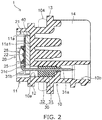
- FIG. 2 is a cross-sectional view taken along line A-A of the vehicular luminaire 1 in FIG. 1 .
- FIG. 3 is a schematic perspective view for exemplifying the form of the end portions of a plurality of power-supply terminals 31 that are on a light-emitting module 20 side.
- the vehicular luminaire 1 is provided with a socket 10, the light-emitting module 20, a power-supply unit 30, and a heat transfer unit 40.
- the socket 10 has a mounting portion 11, a bayonet 12, a flange 13, and a thermal radiation fin 14.
- the mounting portion 11 is provided on the surface of the flange 13 that is on the side which is opposite to the side on which the thermal radiation fin 14 is provided.
- the outer shape of the mounting portion 11 may be columnar.
- the outer shape of the mounting portion 11 is, for example, cylindrical.
- the mounting portion 11 has a recessed portion 11a, which is open to an end face that is on the side which is opposite to the flange 13 side.
- the light-emitting module 20 is provided on a bottom surface 11a1 of the recessed portion 11a.
- At least one slit 11b may be provided in the mounting portion 11.
- a substrate 21 has a corner portion provided inside the slit 11b.
- the dimension (width dimension) of the slit 11b in the circumferential direction of the mounting portion 11 is slightly larger than the dimension of the corner portion of the substrate 21. Accordingly, the substrate 21 can be positioned by inserting the corner portion of the substrate 21 into the slit 11b.
- the external dimension of the mounting portion 11 can be reduced by the slit 11b being provided. Accordingly, the mounting portion 11 can be reduced in size, and the vehicular luminaire 1 can be reduced in size as a result.
- the bayonet 12 is provided on the outside surface of the mounting portion 11.
- the bayonet 12 projects toward the outside of the vehicular luminaire 1.
- the bayonet 12 faces the flange 13.
- a plurality of the bayonets 12 are provided.
- the bayonet 12 is used when the vehicular luminaire 1 is mounted on a housing 101 of a vehicular lamp 100.
- the bayonet 12 is used for twist lock.
- the flange 13 has a plate shape.
- the flange 13 is capable of having a disk shape or the like.
- the outside surface of the flange 13 is positioned outside the outside surface of the bayonet 12 in the vehicular luminaire 1.
- the thermal radiation fin 14 is provided on the side that is opposite to the mounting portion 11 side of the flange 13. At least one thermal radiation fin 14 may be provided.
- the socket 10 that is exemplified in FIGS. 1 and 2 is provided with a plurality of the thermal radiation fins. The plurality of thermal radiation fins 14 may be provided side by side in a predetermined direction.
- the thermal radiation fin 14 is capable of having a plate shape.
- the socket 10 is provided with a hole 10b into which a connector 105 is inserted.
- the connector 105 having a seal member 105a is inserted into the hole 10b. Accordingly, the cross-sectional shape of the hole 10b is adapted to the cross-sectional shape of the connector 105 having the seal member 105a.
- the heat that is generated in the light-emitting module 20 is mainly transferred to the thermal radiation fin 14 via the mounting portion 11 and the flange 13.
- the heat transferred to the thermal radiation fin 14 is mainly released from the thermal radiation fin 14 to the outside.
- the socket 10 is formed of a highly heat-conductive material.
- the socket 10 may be formed of a metal such as an aluminum alloy.
- the socket 10 is light in weight and capable of thermally radiating the heat generated in the light-emitting module 20 with efficiency.
- the mounting portion 11, the bayonet 12, the flange 13, and the thermal radiation fin 14 are formed of a highly heat-conductive resin.
- the highly heat-conductive resin contains, for example, a filler made of an inorganic material and a resin.
- the highly heat-conductive resin is, for example, a resin such as polyethylene terephthalate (PET) and nylon mixed with a filler made of carbon, aluminum oxide, or the like.
- the mounting portion 11, the bayonet 12, the flange 13, and the thermal radiation fin 14 may be molded integrally with the power-supply unit 30 by an insert molding method or the like.
- the socket 10 that contains the highly heat-conductive resin with the mounting portion 11, the bayonet 12, the flange 13, and the thermal radiation fin 14 integrally molded, the heat that is generated in the light-emitting module 20 can be thermally radiated with efficiency. In addition, the weight of the socket 10 can be reduced.
- the light-emitting module 20 has the substrate 21, a light-emitting element 22, a resistor 23, a control element 24, a frame portion 25, and a sealing portion 26.
- the substrate 21 is provided on one end portion side of the socket 10.
- the substrate 21 is provided in the heat transfer unit 40 via a bonding portion. In other words, the substrate 21 is bonded to the heat transfer unit 40.
- the substrate 21 has a plate shape.
- the planar shape of the substrate 21 may be, for example, quadrangular.
- the material and the structure of the substrate 21 are not particularly limited.
- the substrate 21 may be formed of an inorganic material such as ceramics (aluminum oxide, aluminum nitride, or the like), an organic material such as paper phenol and glass epoxy, or the like.
- the substrate 21 may be obtained by the surface of a metal plate being coated with an insulating material.
- the insulating material may be made of an organic material or an inorganic material.
- the substrate 21 When the light-emitting element 22 generates a large amount of heat, it is preferable from the viewpoint of thermal radiation to form the substrate 21 by using a highly heat-conductive material.
- the highly heat-conductive material include ceramics such as aluminum oxide and aluminum nitride, a highly heat-conductive resin, and a material obtained by the surface of a metal plate being coated with an insulating material.
- the substrate 21 may have a single layer or multiple layers.
- the substrate 21 has a surface provided with a wiring pattern 21a.
- the wiring pattern 21a can also be provided on both surfaces of the substrate 21.
- the wiring pattern 21a may be provided on at least one surface of the substrate 21.
- the wiring pattern 21a may be formed of, for example, a material containing silver as a main component.
- the wiring pattern 21a may be formed of, for example, silver or a silver alloy.
- the material of the wiring pattern 21a is not limited to a material containing silver as a main component.
- the wiring pattern 21a can also be formed of, for example, a material containing copper as a main component.
- the light-emitting element 22 is provided on the side of the substrate 21 that is opposite to the bottom surface 11a1 side of the recessed portion 11a.
- the light-emitting element 22 is provided on the substrate 21.
- the light-emitting element 22 is electrically connected to the wiring pattern 21a.
- the light-emitting element 22 may be, for example, a light-emitting diode, an organic light-emitting diode, a laser diode, or the like.
- At least one light-emitting element 22 may be provided.
- the plurality of light-emitting elements 22 may be connected in series to each other.
- the light-emitting element 22 is connected in series to the resistor 23.
- the light-emitting element 22 may be a chip-shaped light-emitting element.
- the chip-shaped light-emitting element 22 is mounted by a chip on board (COB). In this manner, it is possible to provide many light-emitting elements 22 in a narrow region. Accordingly, the light-emitting module 20 can be reduced in size, and the vehicular luminaire 1 can be reduced in size as a result.
- the light-emitting element 22 is electrically connected to the wiring pattern 21a by wiring 21b.
- the light-emitting element 22 and the wiring pattern 21a may be electrically connected by, for example, a wire bonding method.
- the light-emitting element 22 can also be a surface mounting-type light-emitting element or a shell-type light-emitting element having a lead wire.
- the resistor 23 is provided on the side of the substrate 21 that is opposite to the bottom surface 11a1 side of the recessed portion 11a.
- the resistor 23 is provided on the substrate 21.
- the resistor 23 is electrically connected to the wiring pattern 21a.
- the resistor 23 may be, for example, a surface mounting-type resistor, a resistor (metal oxide film resistor) having a lead wire, or a film-shaped resistor formed by a screen printing method or the like.
- the resistor 23 that is exemplified in FIG. 1 is a film-shaped resistor.
- the material of the film-shaped resistor may be, for example, ruthenium oxide (RuO 2 ).
- the film-shaped resistor may be formed by, for example, a screen printing method and a firing method.
- the resistor 23 is a film-shaped resistor, the contact area between the resistor 23 and the substrate 21 can be increased, and thus thermal radiation can be improved.
- a plurality of the resistors 23 can be formed at the same time. Accordingly, it is possible to improve productivity and it is possible to suppress resistance value variations in the plurality of resistors 23.
- the forward voltage characteristics of the light-emitting element 22 have variations. Accordingly, when the applied voltage between anode and ground terminals is constant, the brightness (luminous flux, brightness, luminous intensity, and illuminance) of the light that is irradiated from the light-emitting element 22 varies. Accordingly, the value of the current that flows through the light-emitting element 22 is kept within a predetermined range by the resistor 23 such that the brightness of the light irradiated from the light-emitting element 22 is within a predetermined range. In this case, the value of the current that flows through the light-emitting element 22 is kept within a predetermined range by the resistance value of the resistor 23 being changed.
- the resistor 23 When the resistor 23 is a surface mounting-type resistor, a resistor having a lead wire, or the like, the resistor 23 that has an appropriate resistance value is selected in accordance with the forward voltage characteristics of the light-emitting element 22.
- the resistor 23 When the resistor 23 is a film-shaped resistor, the resistance value can be increased by a part of the resistor 23 being removed. For example, a part of the resistor 23 can be easily removed when the resistor 23 is irradiated with laser light.
- the resistor 23 is not limited to the above exemplification in terms of number, size, disposition, and so on.
- the resistor 23 may be appropriately changed in terms of number, size, disposition, and so on in accordance with, for example, the number and specifications of the light-emitting elements 22.
- the control element 24 is provided on the side of the substrate 21 that is opposite to the bottom surface 11a1 side of the recessed portion 11a.
- the control element 24 is provided on the substrate 21.
- the control element 24 is electrically connected to the wiring pattern 21a.
- the control element 24 is provided so that no reverse voltage is applied to the light-emitting element 22 and pulse noise from a reverse direction is not applied to the light-emitting element 22.
- the control element 24 may be, for example, a diode or the like.
- the control element 24 may be, for example, a surface mounting-type diode or a diode having a lead wire.
- the control element 24 that is exemplified in FIG. 1 is a surface mounting-type diode.
- a pull-down resistor may be provided for detection of disconnection of the light-emitting element 22, prevention of erroneous lighting, and so on. It is also possible to provide a coating portion covering the wiring pattern 21a, the film-shaped resistor, and the like.
- the coating portion may contain a glass material or the like.
- the frame portion 25 and the sealing portion 26 may be provided when the light-emitting element 22 is a chip-shaped light-emitting element.
- the frame portion 25 is provided on the side of the substrate 21 that is opposite to the bottom surface 11a1 side of the recessed portion 11a.
- the frame portion 25 is provided on the substrate 21.
- the frame portion 25 is bonded to the substrate 21.
- the frame portion 25 has, for example, a tubular shape with the light-emitting element 22 disposed inside.
- the frame portion 25 surrounds the plurality of light-emitting elements 22.
- the frame portion 25 may be formed of a resin.
- the resin may be, for example, a thermoplastic resin such as polybutylene terephthalate (PBT), polycarbonate (PC), PET, nylon, polypropylene (PP), polyethylene (PE), or polystyrene (PS).
- the frame portion 25 may be formed of, for example, a white resin or the like as well.
- the inner wall surface of the frame portion 25 is an inclined surface that is inclined in a direction away from the central axis of the frame portion 25 as the distance from the substrate 21 increases. Accordingly, the light emitted from the light-emitting element 22 is partially reflected by the inner wall surface of the frame portion 25 and emitted toward the front surface side of the vehicular luminaire 1.
- the frame portion 25 is capable of serving to define the formation range of the sealing portion 26 and functioning as a reflector.
- the sealing portion 26 is provided inside the frame portion 25.
- the sealing portion 26 is provided so as to cover the inside of the frame portion 25.
- the sealing portion 26 is provided inside the frame portion 25 and covers the light-emitting element 22, the wiring 21b, and so on.
- the sealing portion 26 may be formed of, for example, a translucent material.
- the sealing portion 26 may be formed by, for example, the inside of the frame portion 25 being filled with a resin.
- the resin filling may be performed, for example, by means of a liquid dispensing device such as a dispenser.
- the resin with which the inside of the frame portion 25 is filled may be, for example, a silicone resin or the like.
- the sealing portion 26 is capable of containing a phosphor.
- the phosphor may be, for example, a YAG-based phosphor (yttrium-aluminum-garnet-based phosphor).
- the type of the phosphor may be appropriately changed such that a desired luminescent color is obtained in accordance with the applications of the vehicular luminaire 1 and so on.
- the heat transfer unit 40 is provided between the substrate 21 and the bottom surface 11a1 of the recessed portion 11a.
- the heat transfer unit 40 is provided on the bottom surface 11a1 of the recessed portion 11a via a bonding portion. In other words, the heat transfer unit 40 is bonded to the bottom surface 11a1 of the recessed portion 11a.
- the adhesive for bonding between the heat transfer unit 40 and the substrate 21 and the adhesive for bonding between the heat transfer unit 40 and the bottom surface 11a1 of the recessed portion 11a are highly heat-conductive adhesives.
- each of the adhesives may be an adhesive mixed with a filler using an inorganic material.
- the inorganic material is a highly heat-conductive material (for example, ceramics such as aluminum oxide and aluminum nitride).
- the heat conductivity of the adhesive may be, for example, 0.5 W/(m ⁇ K) or more and 10 W/(m ⁇ K) or less.
- the heat transfer unit 40 may be embedded in the bottom surface 11a1 of the recessed portion 11a by an insert molding method as well.
- the heat transfer unit 40 may be attached to the bottom surface 11a1 of the recessed portion 11a via a layer made of heat-conductive grease (thermal radiation grease).
- the heat-conductive grease is not particularly limited in terms of type and it is possible to use, for example, a mixture of modified silicone and a filler using a highly heat-conductive material (for example, ceramics such as aluminum oxide and aluminum nitride).
- the heat conductivity of the heat-conductive grease may be, for example, 1 W/(m ⁇ K) or more and 5 W/(m ⁇ K) or less.
- the heat transfer unit 40 is provided so that the heat that is generated in the light-emitting module 20 is easily transferred to the socket 10. Accordingly, it is preferable that the heat transfer unit 40 is formed of a highly heat-conductive material.
- the heat transfer unit 40 has a plate shape and may be formed of a metal such as aluminum, aluminum alloy, copper, and copper alloy.
- heat transfer unit 40 is not always necessary and may be omitted, thermal radiation can be improved when the heat transfer unit 40 is provided.
- the power-supply unit 30 has the plurality of power-supply terminals 31 and an insulating portion 32.
- the socket 10 is formed of a highly heat-conductive material.
- a highly heat-conductive material may have electrical conductivity.
- a metal such as an aluminum alloy, a highly heat-conductive resin containing a filler made of carbon, and the like have electrical conductivity.
- the insulating portion 32 is provided for insulation between the plurality of power-supply terminals 31 and the electrically conductive socket 10.
- the insulating portion 32 serves to hold the plurality of power-supply terminals 31 as well.
- the insulating portion 32 may be omitted when the socket 10 is formed of a highly heat-conductive insulating resin (such as a highly heat-conductive resin containing a filler made of aluminum oxide). In this case, the socket 10 holds the plurality of power-supply terminals 31.
- the insulating portion 32 has insulating properties.
- the insulating portion 32 may be formed of an insulating resin.
- the vehicular luminaire 1 that is provided in an automobile has a temperature of use environment of 40°C below zero to 85°C above zero. Accordingly, it is preferable that the thermal expansion coefficient of the material of the insulating portion 32 is as close as possible to the thermal expansion coefficient of the material of the socket 10. In this manner, it is possible to reduce the thermal stress that is generated between the insulating portion 32 and the socket 10.
- the material of the insulating portion 32 may be the resin that constitutes the highly heat-conductive resin contained in the socket 10.
- the insulating portion 32 may be, for example, press-fitted into a hole 10a provided in the socket 10 or bonded to the inner wall of the hole 10a. Also, the socket 10 and the power-supply unit 30 may be integrally molded by an insert molding method.
- the plurality of power-supply terminals 31 are electrically conductive.
- the plurality of power-supply terminals 31 may be formed of a metal such as a copper alloy.
- the plurality of power-supply terminals 31 may be provided side by side in a predetermined direction.
- the plurality of power-supply terminals 31 are provided inside the insulating portion 32.
- the plurality of power-supply terminals 31 extend inside the insulating portion 32 and project from the end face of the insulating portion 32 that is on the light-emitting module 20 side and the end face of the insulating portion 32 that is on the thermal radiation fin 14 side.
- the end portions of the plurality of power-supply terminals 31 that are on the thermal radiation fin 14 side are exposed inside the hole 10b.
- the connector 105 is fitted to the plurality of power-supply terminals 31 exposed inside the hole 10b.
- the end portions of the plurality of power-supply terminals 31 that are on the light-emitting module 20 side are electrically connected to the wiring pattern 21a provided on the substrate 21.
- the end portions of the plurality of power-supply terminals 31 on the light-emitting module 20 side that are exemplified in FIGS. 1 and 2 are soldered to the wiring pattern 21a.
- the power-supply terminal 31 is not limited to the above exemplification in terms of number, disposition, material, and so on.
- the power-supply terminal 31 may be appropriately changed in terms of number, disposition, material, and so on.
- the planar dimension of the substrate 21 provided in the light-emitting module 20 needs to be reduced for the vehicular luminaire 1 to be reduced in size.
- the substrate 21 is provided with the light-emitting element 22, the resistor 23, the control element 24, the frame portion 25, and the sealing portion 26.
- a decrease in total luminous flux may arise or predetermined luminous intensity distribution characteristics may be unobtainable when the sizes of the elements are reduced, the numbers of the elements are reduced, or the mounting density of the elements is increased. In other words, functions required for the vehicular luminaire 1 may be unobtainable.
- respective end portions of a plurality of power-supply terminals are soldered in a state of being inserted in holes provided in a substrate.
- the substrate is provided with the plurality of holes for power-supply terminal insertion and lands respectively surrounding the plurality of holes.
- the plurality of lands are provided, the region where the plurality of power-supply terminals and a wiring pattern are electrically connected to each other is large in area.
- the functions required for the vehicular luminaire 1, such as the total luminous flux and the luminous intensity distribution characteristics, are unlikely to be impaired even if the region where the plurality of power-supply terminals and the wiring pattern are electrically connected to each other is reduced.
- the region where the plurality of power-supply terminals 31 and the wiring pattern 21a are electrically connected to each other is reduced in the vehicular luminaire 1 according to the present embodiment.
- the end portions of the plurality of power-supply terminals 31 that are on the light-emitting module 20 side are bent.
- the plurality of power-supply terminals 31 extend inside the socket 10 with one end portion exposed from the socket 10.
- the vicinity of the end portion is bent toward the substrate 21.
- the end portion is provided on the surface of the substrate 21 that is on the side where the light-emitting element 22 is provided.
- the end portion may also be provided on the surface of the substrate 21 that is on the side which is opposite to the side where the light-emitting element 22 is provided.
- the substrate 21 is not provided with holes for insertion of the plurality of power-supply terminals 31.
- a center line 31b of a part 31c of the power-supply terminal 31 that is bent toward the substrate 21 intersects with a center line 31a of a part extending inside the socket 10 (insulating portion 32).
- An angle ⁇ formed by the center line 31a and the center line 31b is not limited insofar as the power-supply terminal 31 has a tip that can be soldered to the wiring pattern 21a. In this case, the tip of the power-supply terminal 31 is likely to come into contact with the wiring pattern 21a if the angle ⁇ is 90° or less. Accordingly, it is preferable that the angle ⁇ is 90° or less.
- the angle ⁇ is approximately 90° in the power-supply terminal 31 that is exemplified in FIGS. 2 and 3 . In this manner, the power-supply terminal 31 can be manufactured with ease.
- the tip side of the power-supply terminal 31 extends in a direction that is substantially parallel to the surface of the substrate 21. Accordingly, the contact part between the tip side of the power-supply terminal 31 and the wiring pattern 21a can be lengthened. In addition, soldering is facilitated.
- the region where the plurality of power-supply terminals 31 and the wiring pattern 21a are electrically connected to each other can be smaller than when a power-supply terminal is provided in a hole provided in a substrate.
- a region is required between the center of the hole provided in the substrate and the end face of the substrate.
- the region where the plurality of power-supply terminals 31 and the wiring pattern 21a are electrically connected to each other is reduced by an amount corresponding to the region. Accordingly, the size of the substrate 21 is reduced, and the vehicular luminaire 1 can be reduced in size as a result.
- FIGS. 4A and 4B are schematic diagrams for exemplifying the power-supply terminal 31 according to another embodiment.
- the angle ⁇ may be less than 90°. In this manner, the elastic force of the part 31c of the power-supply terminal 31 can be used with ease, and thus contact between the tip part of the power-supply terminal 31 and the wiring pattern 21a is facilitated.
- the angle ⁇ may be less than 90° and a tip part 31c1 of the part 31c of the power-supply terminal 31 that is bent toward the substrate 21 may be substantially parallel to the surface of the substrate 21. In this manner, it is possible to lengthen the contact length between the tip part 31c1 and the wiring pattern 21a. In addition, soldering is facilitated.
- the vehicular luminaire 1 undergoes vibration resulting from traveling or the like and vibration from an engine or the like.
- the vehicular luminaire 1 has a temperature of use environment of 40°C below zero to 85°C above zero. Accordingly, thermal stress is generated between the power-supply terminal 31 and the substrate.
- the angle ⁇ is less than 90° in the power-supply terminal 31 according to the present embodiment. Accordingly, it is possible to absorb vibration and a thermal expansion difference at the part where the power-supply terminal 31 is bent. Accordingly, it is possible to suppress inconvenience such as detachment of the soldering part of the power-supply terminal 31.
- the substrate 21 is provided between the part 31c of the power-supply terminal 31 and the bottom surface 11a1 of the recessed portion 11a.
- the part 31c of the power-supply terminal 31 may be formed by, for example, the tip part of the power-supply terminal 31 being folded after the substrate 21 is provided on the socket 10.
- FIGS. 5A and 5B are schematic diagrams for exemplifying the power-supply terminal 31 according to another embodiment.
- the part 31c of the power-supply terminal 31 may be brought into contact with the surface of the substrate 21 that is on the bottom surface 11a1 side (rear surface side) of the recessed portion 11a.
- the tip part 31c1 of the power-supply terminal 31 may be brought into contact with the surface of the substrate 21 that is on the bottom surface 11a1 side of the recessed portion 11a.
- the power-supply terminal 31 can be bent in advance. Accordingly, manufacturing can be simplified and manufacturing cost reduction can be achieved.
- the wiring patterns 21a may be formed on both surfaces of the substrate 21 and the wiring patterns 21a may be electrically connected to each other with an electrically conductive via or the like.
- soldering may be omitted as the tip of the power-supply terminal 31 is pressed against the substrate 21.
- FIGS. 6A and 6B are schematic diagrams for exemplifying the power-supply terminal 31 that is yet to be folded.
- a notch 31d may be provided at the part where the power-supply terminal 31 is folded. Folding is facilitated in this manner. In addition, folding accuracy improvement can be achieved as springback can be reduced.
- FIGS. 7A and 7B are schematic perspective views for exemplifying the tip shape of the power-supply terminal 31.
- the part 31c of the power-supply terminal 31 preferably has a flat shape.
- the part 31c that is bent toward the substrate 21 preferably has a flat cross-sectional shape.
- the cross-sectional length in the direction that is parallel to the surface of the substrate 21 may be longer than the cross-sectional length in the direction that is perpendicular to the surface of the substrate 21.
- soldering can be facilitated.
- folding accuracy improvement can be achieved as folding-direction variations can be reduced.
- the flat shape may be formed by folding of the power-supply terminal 31 that has a flat cross-sectional shape (such as a rectangular shape).
- the tip of the power-supply terminal 31 that has a circular or quadrangular cross-sectional shape may be crushed to be given a flat shape.
- the tip of the power-supply terminal 31 may be crushed by pressing or the like.
- FIG. 8 is a schematic perspective view for exemplifying insulating portions 28a to 28c.
- the part 31c of the power-supply terminal 31 is formed by folding, and thus a certain length is required. As described above, the vehicular luminaire 1 undergoes vibration, and thus a short circuit may occur between the parts 31c when the plurality of power-supply terminals 31 have a short pitch dimension.
- a short circuit between the parts 31c can be prevented when the insulating portion 28a is provided between the parts 31c.
- the mounting portion 11 may be formed of a highly heat-conductive material.
- the highly heat-conductive material may be electrically conductive. Accordingly, when the distance between the part 31c and the mounting portion 11 is short, a short circuit may occur between the part 31c and the mounting portion 11.
- a short circuit between the part 31c and the mounting portion 11 can be prevented when the insulating portion 28b is provided between the part 31c and the mounting portion 11.
- short circuits can be prevented between the parts 31c and between the part 31c and the mounting portion 11 when the insulating portion 28c that provides covering between the parts 31c and between the part 31c and the mounting portion 11 is provided.
- the insulating portions 28a to 28c may be provided in at least one of the space between the plurality of parts 31c bent toward the substrate 21 and the space between the socket 10 and the plurality of parts 31c bent toward the substrate 21.
- the insulating portions 28a to 28c may be formed by, for example, an insulating resin being supplied.
- the resin supply may be performed, for example, by means of a liquid dispensing device such as a dispenser.
- a silicone resin or the like may be supplied as the resin.
- the socket 10 is formed by an injection molding method, a die casting method, or the like.
- the power-supply unit 30 is formed by the plurality of power-supply terminals 31 being press-fitted into the holes of the insulating portion 32 or the plurality of power-supply terminals 31 and the insulating portion 32 being integrally molded by an insert molding method.
- the light-emitting module 20 is formed.
- the light-emitting element 22, the resistor 23, and the control element 24 are sequentially mounted on the substrate 21 having the wiring pattern 21a.
- the light-emitting element 22 and the wiring pattern 21a are electrically connected to each other by a wire bonding method.
- the frame portion 25 is bonded to the substrate 21 such that the light-emitting element 22 is surrounded.
- the sealing portion 26 is formed by the inside of the frame portion 25 being filled with a resin.
- the resin filling may be performed, for example, by means of a liquid dispensing device such as a dispenser.
- the power-supply unit 30, the heat transfer unit 40, and the light-emitting module 20 are sequentially assembled to the socket 10.
- the part 31c of the power-supply terminal 31 is provided on the surface side of the substrate 21, the part 31c is formed by the tip of the power-supply terminal 31 being folded.
- the plurality of power-supply terminals 31 where the parts 31c are formed in advance may be integrated with the insulating portion 32.
- the light-emitting module 20 is subsequently assembled on the plurality of parts 31c.
- the vehicular luminaire 1 may be manufactured in the above manner.
- the vehicular luminaire manufacturing method according to the present embodiment may include bending the vicinity of the end portions of the plurality of power-supply terminals 31 that are exposed from the socket 10 toward the substrate 21 or providing the substrate 21 on the plurality of power-supply terminals 31 bent in the vicinity of the end portions exposed from the socket 10.
- the vehicular lamp 100 is a front combination light provided in an automobile
- the vehicular lamp 100 is not limited to the front combination light provided in an automobile.
- the vehicular lamp 100 may also be a vehicular lamp provided in an automobile, a railroad vehicle, or the like.
- FIG. 9 is a schematic partial cross-sectional view for exemplifying the vehicular lamp 100.
- the vehicular lamp 100 is provided with the vehicular luminaire 1, the housing 101, a cover 102, an optical element portion 103, a seal member 104, and the connector 105.
- the vehicular luminaire 1 is attached to the housing 101.
- the housing 101 holds the mounting portion 11.
- the housing 101 has a box shape with one end portion side open.
- the housing 101 may be formed of, for example, a resin that does not transmit light.
- An attachment hole 101a into which the part of the mounting portion 11 where the bayonet 12 is provided is inserted is provided in the bottom surface of the housing 101.
- a recessed portion into which the bayonet 12 provided in the mounting portion 11 is inserted is provided at the peripheral edge of the attachment hole 101a.
- the cover 102 is provided so as to block the opening of the housing 101.
- the cover 102 may be formed of a translucent resin or the like.
- the cover 102 is capable of functioning as a lens or the like as well.
- the light that is emitted from the vehicular luminaire 1 is incident on the optical element portion 103.
- the optical element portion 103 reflects, diffuses, guides, and collects the light that is emitted from the vehicular luminaire 1, forms a predetermined luminous intensity distribution pattern, and so on.
- the optical element portion 103 that is exemplified in FIG. 9 is a reflector.
- the optical element portion 103 reflects the light emitted from the vehicular luminaire 1 for a predetermined luminous intensity distribution pattern to be formed.
- the seal member 104 is provided between the flange 13 and the housing 101.
- the seal member 104 may be annular.
- the seal member 104 may be formed of an elastic material such as rubber and silicone resin.
- the seal member 104 When the vehicular luminaire 1 is attached to the vehicular lamp 100, the seal member 104 is sandwiched between the flange 13 and the housing 101. Accordingly, the internal space of the housing 101 is sealed by the seal member 104. In addition, the bayonet 12 is pressed against the housing 101 by the elastic force of the seal member 104. Accordingly, detachment of the vehicular luminaire 1 from the housing 101 can be prevented.
- the connector 105 is fitted to the end portions of the plurality of power-supply terminals 31 exposed inside the hole 10b.
- a power supply (not illustrated) or the like is electrically connected to the connector 105. Accordingly, the power supply (not illustrated) or the like and the light-emitting element 22 are electrically connected to each other by the connector 105 being fitted to the end portions of the plurality of power-supply terminals 31.
- the connector 105 has a step part.
- the seal member 105a is attached to the step part.
- the seal member 105a is provided so as to prevent the inside of the hole 10b from being permeated by water.
- the connector 105 that has the seal member 105a is inserted into the hole 10b, the hole 10b is sealed so as to be watertight.
- the seal member 105a may be annular.
- the seal member 105a may be formed of an elastic material such as rubber and silicone resin.
- the connector 105 may be joined to a socket 10 side element, for example, by means of an adhesive.
Landscapes
- Engineering & Computer Science (AREA)
- General Engineering & Computer Science (AREA)
- Microelectronics & Electronic Packaging (AREA)
- Physics & Mathematics (AREA)
- Optics & Photonics (AREA)
- Arrangement Of Elements, Cooling, Sealing, Or The Like Of Lighting Devices (AREA)
- Non-Portable Lighting Devices Or Systems Thereof (AREA)
- Fastening Of Light Sources Or Lamp Holders (AREA)
Abstract
Description
- Embodiments described herein relate generally to a vehicular luminaire, a vehicular lamp, and a method for manufacturing a vehicular luminaire.
- A vehicular luminaire is provided with a socket, a light-emitting module provided on one end portion side of the socket, and a plurality of power-supply terminals provided inside the socket and electrically connected to the light-emitting module. The light-emitting module has a substrate provided with a wiring pattern and a light-emitting diode (LED) electrically connected to the wiring pattern. One end portion of the plurality of power-supply terminals is soldered to the wiring pattern provided on the substrate.
- Compact vehicular luminaires are in demand nowadays. The planar dimension of a substrate provided in a light-emitting module needs to be reduced for a vehicular luminaire to be reduced in size.
- A light-emitting element, a resistor, and the like are mounted on the substrate with a plurality of power-supply terminals soldered. In this case, a decrease in light-emitting element size, resistor size, and so on and an increase in mounting density are limited in view of vehicular luminaire functions.
- In addition, respective end portions of the plurality of power-supply terminals are soldered in a state of being inserted in holes provided in the substrate. Accordingly, the substrate is provided with the plurality of holes for power-supply terminal insertion and lands respectively surrounding the plurality of holes. When the plurality of lands are provided, the region where the plurality of power-supply terminals and a wiring pattern are electrically connected to each other is large in area.
- Accordingly, a decrease in the planar dimension of the substrate is limited.
- In this regard, development of a technique with which the planar dimension of a substrate can be reduced is desired.
-
-
FIG. 1 is a schematic perspective view for exemplifying a vehicular luminaire according to the present embodiment. -
FIG. 2 is a cross-sectional view taken along line A-A of avehicular luminaire 1 inFIG. 1 . -
FIG. 3 is a schematic perspective view for exemplifying the form of the end portions of a plurality of power-supply terminals that are on a light-emitting module side. -
FIGS. 4A and 4B are schematic diagrams for exemplifying the power-supply terminal according to another embodiment. -
FIGS. 5A and 5B are schematic diagrams for exemplifying the power-supply terminal according to another embodiment. -
FIGS. 6A and 6B are schematic diagrams for exemplifying the power-supply terminal that is yet to be folded. -
FIGS. 7A and 7B are schematic perspective views for exemplifying the tip shape of the power-supply terminal. -
FIG. 8 is a schematic perspective view for exemplifying insulating portions. -
FIG. 9 is a schematic partial cross-sectional view for exemplifying a vehicular lamp. - A vehicular luminaire according to embodiments includes a socket; a substrate provided on the socket and including a wiring pattern on at least one surface; at least one light-emitting element electrically connected to the wiring pattern; and a plurality of power-supply terminals extending inside the socket and including one end portion exposed from the socket, the vicinity of the end portion being bent toward the substrate.
- Hereinafter, embodiments will be exemplified with reference to accompanying drawings. In the drawings, the same components are denoted by the same reference numerals so that detailed description is omitted as appropriate.
- A
vehicular luminaire 1 according to the present embodiment can be provided in an automobile, a railroad vehicle, or the like. Examples of thevehicular luminaire 1 that is provided in an automobile include thevehicular luminaire 1 used in a front combination light (appropriately combining a daylight running lamp (DRL), a position lamp, a turn signal lamp, and so on) and thevehicular luminaire 1 used in a rear combination light (appropriately combining a stop lamp, a tail lamp, a turn signal lamp, a back lamp, a fog lamp, and so on). However, the applications of thevehicular luminaire 1 are not limited to the above description. -
FIG. 1 is a schematic perspective view for exemplifying thevehicular luminaire 1 according to the present embodiment. -
FIG. 2 is a cross-sectional view taken along line A-A of thevehicular luminaire 1 inFIG. 1 . -
FIG. 3 is a schematic perspective view for exemplifying the form of the end portions of a plurality of power-supply terminals 31 that are on a light-emittingmodule 20 side. - As illustrated in
FIGS. 1 and2 , thevehicular luminaire 1 is provided with asocket 10, the light-emitting module 20, a power-supply unit 30, and aheat transfer unit 40. - The
socket 10 has amounting portion 11, abayonet 12, aflange 13, and athermal radiation fin 14. - The
mounting portion 11 is provided on the surface of theflange 13 that is on the side which is opposite to the side on which thethermal radiation fin 14 is provided. The outer shape of themounting portion 11 may be columnar. The outer shape of themounting portion 11 is, for example, cylindrical. Themounting portion 11 has arecessed portion 11a, which is open to an end face that is on the side which is opposite to theflange 13 side. The light-emitting module 20 is provided on a bottom surface 11a1 of the recessedportion 11a. - At least one
slit 11b may be provided in themounting portion 11. Asubstrate 21 has a corner portion provided inside theslit 11b. The dimension (width dimension) of theslit 11b in the circumferential direction of themounting portion 11 is slightly larger than the dimension of the corner portion of thesubstrate 21. Accordingly, thesubstrate 21 can be positioned by inserting the corner portion of thesubstrate 21 into theslit 11b. - The external dimension of the
mounting portion 11 can be reduced by theslit 11b being provided. Accordingly, themounting portion 11 can be reduced in size, and thevehicular luminaire 1 can be reduced in size as a result. - The
bayonet 12 is provided on the outside surface of themounting portion 11. Thebayonet 12 projects toward the outside of thevehicular luminaire 1. Thebayonet 12 faces theflange 13. A plurality of thebayonets 12 are provided. Thebayonet 12 is used when thevehicular luminaire 1 is mounted on ahousing 101 of avehicular lamp 100. Thebayonet 12 is used for twist lock. - The
flange 13 has a plate shape. Theflange 13 is capable of having a disk shape or the like. The outside surface of theflange 13 is positioned outside the outside surface of thebayonet 12 in thevehicular luminaire 1. - The
thermal radiation fin 14 is provided on the side that is opposite to themounting portion 11 side of theflange 13. At least onethermal radiation fin 14 may be provided. Thesocket 10 that is exemplified inFIGS. 1 and2 is provided with a plurality of the thermal radiation fins. The plurality ofthermal radiation fins 14 may be provided side by side in a predetermined direction. Thethermal radiation fin 14 is capable of having a plate shape. - The
socket 10 is provided with ahole 10b into which aconnector 105 is inserted. - The
connector 105 having aseal member 105a is inserted into thehole 10b. Accordingly, the cross-sectional shape of thehole 10b is adapted to the cross-sectional shape of theconnector 105 having theseal member 105a. - The heat that is generated in the light-emitting
module 20 is mainly transferred to thethermal radiation fin 14 via the mountingportion 11 and theflange 13. The heat transferred to thethermal radiation fin 14 is mainly released from thethermal radiation fin 14 to the outside. - Accordingly, it is preferable that the
socket 10 is formed of a highly heat-conductive material. For example, thesocket 10 may be formed of a metal such as an aluminum alloy. - Nowadays, it is desired that the
socket 10 is light in weight and capable of thermally radiating the heat generated in the light-emittingmodule 20 with efficiency. - Accordingly, it is preferable that the mounting
portion 11, thebayonet 12, theflange 13, and thethermal radiation fin 14 are formed of a highly heat-conductive resin. The highly heat-conductive resin contains, for example, a filler made of an inorganic material and a resin. The highly heat-conductive resin is, for example, a resin such as polyethylene terephthalate (PET) and nylon mixed with a filler made of carbon, aluminum oxide, or the like. - The mounting
portion 11, thebayonet 12, theflange 13, and thethermal radiation fin 14 may be molded integrally with the power-supply unit 30 by an insert molding method or the like. - With the
socket 10 that contains the highly heat-conductive resin with the mountingportion 11, thebayonet 12, theflange 13, and thethermal radiation fin 14 integrally molded, the heat that is generated in the light-emittingmodule 20 can be thermally radiated with efficiency. In addition, the weight of thesocket 10 can be reduced. - The light-emitting
module 20 has thesubstrate 21, a light-emittingelement 22, aresistor 23, a control element 24, aframe portion 25, and a sealingportion 26. - The
substrate 21 is provided on one end portion side of thesocket 10. Thesubstrate 21 is provided in theheat transfer unit 40 via a bonding portion. In other words, thesubstrate 21 is bonded to theheat transfer unit 40. - The
substrate 21 has a plate shape. The planar shape of thesubstrate 21 may be, for example, quadrangular. The material and the structure of thesubstrate 21 are not particularly limited. For example, thesubstrate 21 may be formed of an inorganic material such as ceramics (aluminum oxide, aluminum nitride, or the like), an organic material such as paper phenol and glass epoxy, or the like. In addition, thesubstrate 21 may be obtained by the surface of a metal plate being coated with an insulating material. When the surface of the metal plate is coated with the insulating material, the insulating material may be made of an organic material or an inorganic material. When the light-emittingelement 22 generates a large amount of heat, it is preferable from the viewpoint of thermal radiation to form thesubstrate 21 by using a highly heat-conductive material. Examples of the highly heat-conductive material include ceramics such as aluminum oxide and aluminum nitride, a highly heat-conductive resin, and a material obtained by the surface of a metal plate being coated with an insulating material. Thesubstrate 21 may have a single layer or multiple layers. - The
substrate 21 has a surface provided with awiring pattern 21a. As will be described later, thewiring pattern 21a can also be provided on both surfaces of thesubstrate 21. In other words, thewiring pattern 21a may be provided on at least one surface of thesubstrate 21. Thewiring pattern 21a may be formed of, for example, a material containing silver as a main component. Thewiring pattern 21a may be formed of, for example, silver or a silver alloy. However, the material of thewiring pattern 21a is not limited to a material containing silver as a main component. Thewiring pattern 21a can also be formed of, for example, a material containing copper as a main component. - The light-emitting
element 22 is provided on the side of thesubstrate 21 that is opposite to the bottom surface 11a1 side of the recessedportion 11a. The light-emittingelement 22 is provided on thesubstrate 21. The light-emittingelement 22 is electrically connected to thewiring pattern 21a. - The light-emitting
element 22 may be, for example, a light-emitting diode, an organic light-emitting diode, a laser diode, or the like. - At least one light-emitting
element 22 may be provided. When a plurality of the light-emittingelements 22 are provided, the plurality of light-emittingelements 22 may be connected in series to each other. In addition, the light-emittingelement 22 is connected in series to theresistor 23. - The light-emitting
element 22 may be a chip-shaped light-emitting element. The chip-shaped light-emittingelement 22 is mounted by a chip on board (COB). In this manner, it is possible to provide many light-emittingelements 22 in a narrow region. Accordingly, the light-emittingmodule 20 can be reduced in size, and thevehicular luminaire 1 can be reduced in size as a result. The light-emittingelement 22 is electrically connected to thewiring pattern 21a bywiring 21b. The light-emittingelement 22 and thewiring pattern 21a may be electrically connected by, for example, a wire bonding method. - The light-emitting
element 22 can also be a surface mounting-type light-emitting element or a shell-type light-emitting element having a lead wire. - The
resistor 23 is provided on the side of thesubstrate 21 that is opposite to the bottom surface 11a1 side of the recessedportion 11a. Theresistor 23 is provided on thesubstrate 21. Theresistor 23 is electrically connected to thewiring pattern 21a. Theresistor 23 may be, for example, a surface mounting-type resistor, a resistor (metal oxide film resistor) having a lead wire, or a film-shaped resistor formed by a screen printing method or the like. Theresistor 23 that is exemplified inFIG. 1 is a film-shaped resistor. - The material of the film-shaped resistor may be, for example, ruthenium oxide (RuO2). The film-shaped resistor may be formed by, for example, a screen printing method and a firing method. When the
resistor 23 is a film-shaped resistor, the contact area between theresistor 23 and thesubstrate 21 can be increased, and thus thermal radiation can be improved. In addition, a plurality of theresistors 23 can be formed at the same time. Accordingly, it is possible to improve productivity and it is possible to suppress resistance value variations in the plurality ofresistors 23. - The forward voltage characteristics of the light-emitting
element 22 have variations. Accordingly, when the applied voltage between anode and ground terminals is constant, the brightness (luminous flux, brightness, luminous intensity, and illuminance) of the light that is irradiated from the light-emittingelement 22 varies. Accordingly, the value of the current that flows through the light-emittingelement 22 is kept within a predetermined range by theresistor 23 such that the brightness of the light irradiated from the light-emittingelement 22 is within a predetermined range. In this case, the value of the current that flows through the light-emittingelement 22 is kept within a predetermined range by the resistance value of theresistor 23 being changed. - When the
resistor 23 is a surface mounting-type resistor, a resistor having a lead wire, or the like, theresistor 23 that has an appropriate resistance value is selected in accordance with the forward voltage characteristics of the light-emittingelement 22. When theresistor 23 is a film-shaped resistor, the resistance value can be increased by a part of theresistor 23 being removed. For example, a part of theresistor 23 can be easily removed when theresistor 23 is irradiated with laser light. Theresistor 23 is not limited to the above exemplification in terms of number, size, disposition, and so on. Theresistor 23 may be appropriately changed in terms of number, size, disposition, and so on in accordance with, for example, the number and specifications of the light-emittingelements 22. - The control element 24 is provided on the side of the
substrate 21 that is opposite to the bottom surface 11a1 side of the recessedportion 11a. The control element 24 is provided on thesubstrate 21. The control element 24 is electrically connected to thewiring pattern 21a. The control element 24 is provided so that no reverse voltage is applied to the light-emittingelement 22 and pulse noise from a reverse direction is not applied to the light-emittingelement 22. - The control element 24 may be, for example, a diode or the like. The control element 24 may be, for example, a surface mounting-type diode or a diode having a lead wire. The control element 24 that is exemplified in
FIG. 1 is a surface mounting-type diode. - A pull-down resistor may be provided for detection of disconnection of the light-emitting
element 22, prevention of erroneous lighting, and so on. It is also possible to provide a coating portion covering thewiring pattern 21a, the film-shaped resistor, and the like. The coating portion may contain a glass material or the like. - The
frame portion 25 and the sealingportion 26 may be provided when the light-emittingelement 22 is a chip-shaped light-emitting element. - The
frame portion 25 is provided on the side of thesubstrate 21 that is opposite to the bottom surface 11a1 side of the recessedportion 11a. Theframe portion 25 is provided on thesubstrate 21. Theframe portion 25 is bonded to thesubstrate 21. Theframe portion 25 has, for example, a tubular shape with the light-emittingelement 22 disposed inside. For example, theframe portion 25 surrounds the plurality of light-emittingelements 22. Theframe portion 25 may be formed of a resin. The resin may be, for example, a thermoplastic resin such as polybutylene terephthalate (PBT), polycarbonate (PC), PET, nylon, polypropylene (PP), polyethylene (PE), or polystyrene (PS). - In addition, it is possible to improve reflectance with respect to the light that is emitted from the light-emitting
element 22 by mixing a resin with particles of titanium oxide or the like. The particles are not limited to titanium oxide particles, and particles made of a material having a high reflectance with respect to the light that is emitted from the light-emittingelement 22 may be mixed. Theframe portion 25 may be formed of, for example, a white resin or the like as well. - The inner wall surface of the
frame portion 25 is an inclined surface that is inclined in a direction away from the central axis of theframe portion 25 as the distance from thesubstrate 21 increases. Accordingly, the light emitted from the light-emittingelement 22 is partially reflected by the inner wall surface of theframe portion 25 and emitted toward the front surface side of thevehicular luminaire 1. In other words, theframe portion 25 is capable of serving to define the formation range of the sealingportion 26 and functioning as a reflector. - The sealing
portion 26 is provided inside theframe portion 25. The sealingportion 26 is provided so as to cover the inside of theframe portion 25. In other words, the sealingportion 26 is provided inside theframe portion 25 and covers the light-emittingelement 22, thewiring 21b, and so on. The sealingportion 26 may be formed of, for example, a translucent material. The sealingportion 26 may be formed by, for example, the inside of theframe portion 25 being filled with a resin. The resin filling may be performed, for example, by means of a liquid dispensing device such as a dispenser. The resin with which the inside of theframe portion 25 is filled may be, for example, a silicone resin or the like. - The sealing
portion 26 is capable of containing a phosphor. The phosphor may be, for example, a YAG-based phosphor (yttrium-aluminum-garnet-based phosphor). The type of the phosphor may be appropriately changed such that a desired luminescent color is obtained in accordance with the applications of thevehicular luminaire 1 and so on. - It is also possible to provide only the sealing
portion 26 without providing theframe portion 25. When only the sealingportion 26 is provided, the sealingportion 26 that is dome-shaped is provided on thesubstrate 21. - The
heat transfer unit 40 is provided between thesubstrate 21 and the bottom surface 11a1 of the recessedportion 11a. Theheat transfer unit 40 is provided on the bottom surface 11a1 of the recessedportion 11a via a bonding portion. In other words, theheat transfer unit 40 is bonded to the bottom surface 11a1 of the recessedportion 11a. - It is preferable that the adhesive for bonding between the
heat transfer unit 40 and thesubstrate 21 and the adhesive for bonding between theheat transfer unit 40 and the bottom surface 11a1 of the recessedportion 11a are highly heat-conductive adhesives. For example, each of the adhesives may be an adhesive mixed with a filler using an inorganic material. It is preferable that the inorganic material is a highly heat-conductive material (for example, ceramics such as aluminum oxide and aluminum nitride). The heat conductivity of the adhesive may be, for example, 0.5 W/(m·K) or more and 10 W/(m·K) or less. - The
heat transfer unit 40 may be embedded in the bottom surface 11a1 of the recessedportion 11a by an insert molding method as well. In addition, theheat transfer unit 40 may be attached to the bottom surface 11a1 of the recessedportion 11a via a layer made of heat-conductive grease (thermal radiation grease). The heat-conductive grease is not particularly limited in terms of type and it is possible to use, for example, a mixture of modified silicone and a filler using a highly heat-conductive material (for example, ceramics such as aluminum oxide and aluminum nitride). The heat conductivity of the heat-conductive grease may be, for example, 1 W/(m·K) or more and 5 W/(m·K) or less. - The
heat transfer unit 40 is provided so that the heat that is generated in the light-emittingmodule 20 is easily transferred to thesocket 10. Accordingly, it is preferable that theheat transfer unit 40 is formed of a highly heat-conductive material. Theheat transfer unit 40 has a plate shape and may be formed of a metal such as aluminum, aluminum alloy, copper, and copper alloy. - Although the
heat transfer unit 40 is not always necessary and may be omitted, thermal radiation can be improved when theheat transfer unit 40 is provided. - The power-
supply unit 30 has the plurality of power-supply terminals 31 and an insulatingportion 32. - As described above, it is preferable that the
socket 10 is formed of a highly heat-conductive material. However, a highly heat-conductive material may have electrical conductivity. For example, a metal such as an aluminum alloy, a highly heat-conductive resin containing a filler made of carbon, and the like have electrical conductivity. Accordingly, the insulatingportion 32 is provided for insulation between the plurality of power-supply terminals 31 and the electricallyconductive socket 10. The insulatingportion 32 serves to hold the plurality of power-supply terminals 31 as well. The insulatingportion 32 may be omitted when thesocket 10 is formed of a highly heat-conductive insulating resin (such as a highly heat-conductive resin containing a filler made of aluminum oxide). In this case, thesocket 10 holds the plurality of power-supply terminals 31. - The insulating
portion 32 has insulating properties. The insulatingportion 32 may be formed of an insulating resin. - The
vehicular luminaire 1 that is provided in an automobile has a temperature of use environment of 40°C below zero to 85°C above zero. Accordingly, it is preferable that the thermal expansion coefficient of the material of the insulatingportion 32 is as close as possible to the thermal expansion coefficient of the material of thesocket 10. In this manner, it is possible to reduce the thermal stress that is generated between the insulatingportion 32 and thesocket 10. For example, the material of the insulatingportion 32 may be the resin that constitutes the highly heat-conductive resin contained in thesocket 10. - The insulating
portion 32 may be, for example, press-fitted into ahole 10a provided in thesocket 10 or bonded to the inner wall of thehole 10a. Also, thesocket 10 and the power-supply unit 30 may be integrally molded by an insert molding method. - The plurality of power-
supply terminals 31 are electrically conductive. The plurality of power-supply terminals 31 may be formed of a metal such as a copper alloy. The plurality of power-supply terminals 31 may be provided side by side in a predetermined direction. The plurality of power-supply terminals 31 are provided inside the insulatingportion 32. The plurality of power-supply terminals 31 extend inside the insulatingportion 32 and project from the end face of the insulatingportion 32 that is on the light-emittingmodule 20 side and the end face of the insulatingportion 32 that is on thethermal radiation fin 14 side. - The end portions of the plurality of power-
supply terminals 31 that are on thethermal radiation fin 14 side are exposed inside thehole 10b. Theconnector 105 is fitted to the plurality of power-supply terminals 31 exposed inside thehole 10b. - The end portions of the plurality of power-
supply terminals 31 that are on the light-emittingmodule 20 side are electrically connected to thewiring pattern 21a provided on thesubstrate 21. The end portions of the plurality of power-supply terminals 31 on the light-emittingmodule 20 side that are exemplified inFIGS. 1 and2 are soldered to thewiring pattern 21a. - The power-
supply terminal 31 is not limited to the above exemplification in terms of number, disposition, material, and so on. The power-supply terminal 31 may be appropriately changed in terms of number, disposition, material, and so on. - The planar dimension of the
substrate 21 provided in the light-emittingmodule 20 needs to be reduced for thevehicular luminaire 1 to be reduced in size. - The
substrate 21 is provided with the light-emittingelement 22, theresistor 23, the control element 24, theframe portion 25, and the sealingportion 26. In this case, it is possible to reduce the planar dimension of thesubstrate 21 by reducing the sizes of the elements, reducing the numbers of the elements, or increasing the mounting density of the elements. However, a decrease in total luminous flux may arise or predetermined luminous intensity distribution characteristics may be unobtainable when the sizes of the elements are reduced, the numbers of the elements are reduced, or the mounting density of the elements is increased. In other words, functions required for thevehicular luminaire 1 may be unobtainable. - Accordingly, it is difficult to reduce the planar dimension of the
substrate 21 by reducing the area occupied by the elements. - In general, respective end portions of a plurality of power-supply terminals are soldered in a state of being inserted in holes provided in a substrate. Accordingly, the substrate is provided with the plurality of holes for power-supply terminal insertion and lands respectively surrounding the plurality of holes. When the plurality of lands are provided, the region where the plurality of power-supply terminals and a wiring pattern are electrically connected to each other is large in area.
- In this case, the functions required for the
vehicular luminaire 1, such as the total luminous flux and the luminous intensity distribution characteristics, are unlikely to be impaired even if the region where the plurality of power-supply terminals and the wiring pattern are electrically connected to each other is reduced. - In this regard, the region where the plurality of power-
supply terminals 31 and thewiring pattern 21a are electrically connected to each other is reduced in thevehicular luminaire 1 according to the present embodiment. - As illustrated in
FIGS. 2 and3 , the end portions of the plurality of power-supply terminals 31 that are on the light-emittingmodule 20 side are bent. In other words, the plurality of power-supply terminals 31 extend inside thesocket 10 with one end portion exposed from thesocket 10. The vicinity of the end portion is bent toward thesubstrate 21. The end portion is provided on the surface of thesubstrate 21 that is on the side where the light-emittingelement 22 is provided. As will be described later, the end portion may also be provided on the surface of thesubstrate 21 that is on the side which is opposite to the side where the light-emittingelement 22 is provided. In other words, thesubstrate 21 is not provided with holes for insertion of the plurality of power-supply terminals 31. - A
center line 31b of apart 31c of the power-supply terminal 31 that is bent toward thesubstrate 21 intersects with acenter line 31a of a part extending inside the socket 10 (insulating portion 32). - An angle θ formed by the
center line 31a and thecenter line 31b is not limited insofar as the power-supply terminal 31 has a tip that can be soldered to thewiring pattern 21a. In this case, the tip of the power-supply terminal 31 is likely to come into contact with thewiring pattern 21a if the angle θ is 90° or less. Accordingly, it is preferable that the angle θ is 90° or less. - The angle θ is approximately 90° in the power-
supply terminal 31 that is exemplified inFIGS. 2 and3 . In this manner, the power-supply terminal 31 can be manufactured with ease. - The tip side of the power-
supply terminal 31 extends in a direction that is substantially parallel to the surface of thesubstrate 21. Accordingly, the contact part between the tip side of the power-supply terminal 31 and thewiring pattern 21a can be lengthened. In addition, soldering is facilitated. - With the power-
supply terminal 31 according to the present embodiment, the region where the plurality of power-supply terminals 31 and thewiring pattern 21a are electrically connected to each other can be smaller than when a power-supply terminal is provided in a hole provided in a substrate. For example, when the hole is provided in the substrate, a region is required between the center of the hole provided in the substrate and the end face of the substrate. With the power-supply terminal 31 according to the present embodiment, the region where the plurality of power-supply terminals 31 and thewiring pattern 21a are electrically connected to each other is reduced by an amount corresponding to the region. Accordingly, the size of thesubstrate 21 is reduced, and thevehicular luminaire 1 can be reduced in size as a result. -
FIGS. 4A and 4B are schematic diagrams for exemplifying the power-supply terminal 31 according to another embodiment. - As illustrated in
FIG. 4A , the angle θ may be less than 90°. In this manner, the elastic force of thepart 31c of the power-supply terminal 31 can be used with ease, and thus contact between the tip part of the power-supply terminal 31 and thewiring pattern 21a is facilitated. - As illustrated in
FIG. 4B , the angle θ may be less than 90° and a tip part 31c1 of thepart 31c of the power-supply terminal 31 that is bent toward thesubstrate 21 may be substantially parallel to the surface of thesubstrate 21. In this manner, it is possible to lengthen the contact length between the tip part 31c1 and thewiring pattern 21a. In addition, soldering is facilitated. - The
vehicular luminaire 1 undergoes vibration resulting from traveling or the like and vibration from an engine or the like. - As described above, the
vehicular luminaire 1 has a temperature of use environment of 40°C below zero to 85°C above zero. Accordingly, thermal stress is generated between the power-supply terminal 31 and the substrate. - The angle θ is less than 90° in the power-
supply terminal 31 according to the present embodiment. Accordingly, it is possible to absorb vibration and a thermal expansion difference at the part where the power-supply terminal 31 is bent. Accordingly, it is possible to suppress inconvenience such as detachment of the soldering part of the power-supply terminal 31. - In the power-
supply terminal 31 that is exemplified inFIGS. 3 ,4A, and 4B , thesubstrate 21 is provided between thepart 31c of the power-supply terminal 31 and the bottom surface 11a1 of the recessedportion 11a. In this case, thepart 31c of the power-supply terminal 31 may be formed by, for example, the tip part of the power-supply terminal 31 being folded after thesubstrate 21 is provided on thesocket 10. -
FIGS. 5A and 5B are schematic diagrams for exemplifying the power-supply terminal 31 according to another embodiment. - As illustrated in
FIG. 5A , thepart 31c of the power-supply terminal 31 may be brought into contact with the surface of thesubstrate 21 that is on the bottom surface 11a1 side (rear surface side) of the recessedportion 11a. - As illustrated in
FIG. 5B , the tip part 31c1 of the power-supply terminal 31 may be brought into contact with the surface of thesubstrate 21 that is on the bottom surface 11a1 side of the recessedportion 11a. - In this manner, the power-
supply terminal 31 can be bent in advance. Accordingly, manufacturing can be simplified and manufacturing cost reduction can be achieved. - In this case, the
wiring patterns 21a may be formed on both surfaces of thesubstrate 21 and thewiring patterns 21a may be electrically connected to each other with an electrically conductive via or the like. - In addition, soldering may be omitted as the tip of the power-
supply terminal 31 is pressed against thesubstrate 21. -
FIGS. 6A and 6B are schematic diagrams for exemplifying the power-supply terminal 31 that is yet to be folded. - As illustrated in
FIGS. 6A and 6B , anotch 31d may be provided at the part where the power-supply terminal 31 is folded. Folding is facilitated in this manner. In addition, folding accuracy improvement can be achieved as springback can be reduced. -
FIGS. 7A and 7B are schematic perspective views for exemplifying the tip shape of the power-supply terminal 31. - As illustrated in
FIGS. 7A and 7B , thepart 31c of the power-supply terminal 31 preferably has a flat shape. In other words, thepart 31c that is bent toward thesubstrate 21 preferably has a flat cross-sectional shape. For example, the cross-sectional length in the direction that is parallel to the surface of thesubstrate 21 may be longer than the cross-sectional length in the direction that is perpendicular to the surface of thesubstrate 21. In this manner, the contact area between the power-supply terminal 31 and thewiring pattern 21a can be increased. In addition, soldering can be facilitated. Further, folding accuracy improvement can be achieved as folding-direction variations can be reduced. - As illustrated in
FIG. 7A , the flat shape may be formed by folding of the power-supply terminal 31 that has a flat cross-sectional shape (such as a rectangular shape). - In addition, as illustrated in
FIG. 7B , the tip of the power-supply terminal 31 that has a circular or quadrangular cross-sectional shape may be crushed to be given a flat shape. For example, the tip of the power-supply terminal 31 may be crushed by pressing or the like. -
FIG. 8 is a schematic perspective view for exemplifying insulatingportions 28a to 28c. - The
part 31c of the power-supply terminal 31 is formed by folding, and thus a certain length is required. As described above, thevehicular luminaire 1 undergoes vibration, and thus a short circuit may occur between theparts 31c when the plurality of power-supply terminals 31 have a short pitch dimension. - As illustrated in
FIG. 8 , a short circuit between theparts 31c can be prevented when the insulatingportion 28a is provided between theparts 31c. - As described above, the mounting
portion 11 may be formed of a highly heat-conductive material. The highly heat-conductive material may be electrically conductive. Accordingly, when the distance between thepart 31c and the mountingportion 11 is short, a short circuit may occur between thepart 31c and the mountingportion 11. - As illustrated in
FIG. 8 , a short circuit between thepart 31c and the mountingportion 11 can be prevented when the insulatingportion 28b is provided between thepart 31c and the mountingportion 11. - As illustrated in
FIG. 8 , short circuits can be prevented between theparts 31c and between thepart 31c and the mountingportion 11 when the insulatingportion 28c that provides covering between theparts 31c and between thepart 31c and the mountingportion 11 is provided. - In other words, the insulating
portions 28a to 28c may be provided in at least one of the space between the plurality ofparts 31c bent toward thesubstrate 21 and the space between thesocket 10 and the plurality ofparts 31c bent toward thesubstrate 21. - The insulating
portions 28a to 28c may be formed by, for example, an insulating resin being supplied. The resin supply may be performed, for example, by means of a liquid dispensing device such as a dispenser. A silicone resin or the like may be supplied as the resin. - Next, a method for manufacturing the vehicular luminaire will be described.
- The
socket 10 is formed by an injection molding method, a die casting method, or the like. - The power-
supply unit 30 is formed by the plurality of power-supply terminals 31 being press-fitted into the holes of the insulatingportion 32 or the plurality of power-supply terminals 31 and the insulatingportion 32 being integrally molded by an insert molding method. - In addition, the light-emitting
module 20 is formed. - First, the light-emitting
element 22, theresistor 23, and the control element 24 are sequentially mounted on thesubstrate 21 having thewiring pattern 21a. - Subsequently, the light-emitting
element 22 and thewiring pattern 21a are electrically connected to each other by a wire bonding method. - Subsequently, the
frame portion 25 is bonded to thesubstrate 21 such that the light-emittingelement 22 is surrounded. - Subsequently, the sealing
portion 26 is formed by the inside of theframe portion 25 being filled with a resin. The resin filling may be performed, for example, by means of a liquid dispensing device such as a dispenser. - Next, the power-
supply unit 30, theheat transfer unit 40, and the light-emittingmodule 20 are sequentially assembled to thesocket 10. - When the
part 31c of the power-supply terminal 31 is provided on the surface side of thesubstrate 21, thepart 31c is formed by the tip of the power-supply terminal 31 being folded. - Subsequently, the
part 31c of the power-supply terminal 31 and thewiring pattern 21a are soldered. - When the
part 31c of the power-supply terminal 31 is provided on the rear surface side of thesubstrate 21, the plurality of power-supply terminals 31 where theparts 31c are formed in advance may be integrated with the insulatingportion 32. The light-emittingmodule 20 is subsequently assembled on the plurality ofparts 31c. - The
vehicular luminaire 1 may be manufactured in the above manner. - As described above, the vehicular luminaire manufacturing method according to the present embodiment may include bending the vicinity of the end portions of the plurality of power-
supply terminals 31 that are exposed from thesocket 10 toward thesubstrate 21 or providing thesubstrate 21 on the plurality of power-supply terminals 31 bent in the vicinity of the end portions exposed from thesocket 10. - The content of each may be identical to the above description, and thus will not be described in detail.
- Next, the
vehicular lamp 100 will be exemplified. - In the following description, a case where the
vehicular lamp 100 is a front combination light provided in an automobile will be described as an example. However, thevehicular lamp 100 is not limited to the front combination light provided in an automobile. Thevehicular lamp 100 may also be a vehicular lamp provided in an automobile, a railroad vehicle, or the like. -
FIG. 9 is a schematic partial cross-sectional view for exemplifying thevehicular lamp 100. - As illustrated in
FIG. 9 , thevehicular lamp 100 is provided with thevehicular luminaire 1, thehousing 101, acover 102, anoptical element portion 103, aseal member 104, and theconnector 105. - The
vehicular luminaire 1 is attached to thehousing 101. Thehousing 101 holds the mountingportion 11. Thehousing 101 has a box shape with one end portion side open. Thehousing 101 may be formed of, for example, a resin that does not transmit light. Anattachment hole 101a into which the part of the mountingportion 11 where thebayonet 12 is provided is inserted is provided in the bottom surface of thehousing 101. A recessed portion into which thebayonet 12 provided in the mountingportion 11 is inserted is provided at the peripheral edge of theattachment hole 101a. Although a case where theattachment hole 101a is directly provided in thehousing 101 is exemplified above, an attachment member having theattachment hole 101a may be provided in thehousing 101 instead. - When the
vehicular luminaire 1 is attached to thevehicular lamp 100, the part of the mountingportion 11 where thebayonet 12 is provided is inserted into theattachment hole 101a and thevehicular luminaire 1 is rotated. Then, thebayonet 12 is held in the recessed portion provided at the peripheral edge of theattachment hole 101a. This attachment method is called twist lock. - The
cover 102 is provided so as to block the opening of thehousing 101. Thecover 102 may be formed of a translucent resin or the like. Thecover 102 is capable of functioning as a lens or the like as well. - The light that is emitted from the
vehicular luminaire 1 is incident on theoptical element portion 103. Theoptical element portion 103 reflects, diffuses, guides, and collects the light that is emitted from thevehicular luminaire 1, forms a predetermined luminous intensity distribution pattern, and so on. - For example, the
optical element portion 103 that is exemplified inFIG. 9 is a reflector. In this case, theoptical element portion 103 reflects the light emitted from thevehicular luminaire 1 for a predetermined luminous intensity distribution pattern to be formed. - The
seal member 104 is provided between theflange 13 and thehousing 101. Theseal member 104 may be annular. Theseal member 104 may be formed of an elastic material such as rubber and silicone resin. - When the
vehicular luminaire 1 is attached to thevehicular lamp 100, theseal member 104 is sandwiched between theflange 13 and thehousing 101. Accordingly, the internal space of thehousing 101 is sealed by theseal member 104. In addition, thebayonet 12 is pressed against thehousing 101 by the elastic force of theseal member 104. Accordingly, detachment of thevehicular luminaire 1 from thehousing 101 can be prevented. - The
connector 105 is fitted to the end portions of the plurality of power-supply terminals 31 exposed inside thehole 10b. A power supply (not illustrated) or the like is electrically connected to theconnector 105. Accordingly, the power supply (not illustrated) or the like and the light-emittingelement 22 are electrically connected to each other by theconnector 105 being fitted to the end portions of the plurality of power-supply terminals 31. - The
connector 105 has a step part. Theseal member 105a is attached to the step part. Theseal member 105a is provided so as to prevent the inside of thehole 10b from being permeated by water. When theconnector 105 that has theseal member 105a is inserted into thehole 10b, thehole 10b is sealed so as to be watertight. - The
seal member 105a may be annular. Theseal member 105a may be formed of an elastic material such as rubber and silicone resin. Theconnector 105 may be joined to asocket 10 side element, for example, by means of an adhesive. - While certain embodiments have been described, these embodiments have been presented by way of example only, and are not intended to limit the scope of the inventions. Indeed, the novel embodiments described herein may be embodied in a variety of other forms; furthermore, various omissions, substitutions and changes in the form of the embodiments described herein may be made without departing from the spirit of the inventions. The accompanying claims and their equivalents are intended to cover such forms or modifications as would fall within the scope and spirit of the inventions. Moreover, above-mentioned embodiments may be combined mutually and may be carried out.
Claims (9)
- A vehicular luminaire (1) comprising:a socket (10);a substrate (21) provided on the socket (10) and including a wiring pattern (21a) on at least one surface;at least one light-emitting element (22) electrically connected to the wiring pattern (21a); anda plurality of power-supply terminals (31) extending inside the socket (10) and including one end portion exposed from the socket (10), a vicinity of the end portion being bent toward the substrate (21).
- The luminaire (1) according to claim 1, wherein the end portion is provided on a surface of the substrate (21) on a side where the light-emitting element (22) is provided or a surface of the substrate (21) on a side opposite to the side where the light-emitting element (22) is provided.
- The luminaire (1) according to claim 1 or 2, wherein a center line (31b) of a part (31c) of the power-supply terminal (31) bent toward the substrate (21) intersects with a center line (31a) of a part extending inside the socket (10).
- The luminaire (1) according to any one of claims 1 to 3, wherein an angle formed by the center line (31b) of the part (31c) bent toward the substrate (21) and the center line (31a) of the part extending inside the socket (10) is 90° or less.
- The luminaire (1) according to claim 4, wherein the angle is less than 90° and a tip part (31c1) of the part (31c) bent toward the substrate (21) is substantially parallel to a surface of the substrate (21).
- The luminaire (1) according to any one of claims 1 to 5, wherein the part (31c) bent toward the substrate (21) is flat in cross-sectional shape.
- The luminaire (1) according to any one of claims 1 to 6, further comprising insulating portions (28a to 28c) provided in at least one of a space between a plurality of the parts bent toward the substrate (21) and a space between the socket (10) and the plurality of parts (31c) bent toward the substrate (21).
- A vehicular lamp (100) comprising:the luminaire (1) according to any one of claims 1 to 7; anda housing (101) to which the luminaire (1) is attached.
- A method for manufacturing the luminaire (1) according to any one of claims 1 to 7, comprising:bending the vicinity of the end portions of the plurality of power-supply terminals (31) exposed from the socket (10) toward the substrate (21); orproviding the substrate (21) on the plurality of power-supply terminals (31) bent in the vicinity of the end portions exposed from the socket (10).
Applications Claiming Priority (1)
| Application Number | Priority Date | Filing Date | Title |
|---|---|---|---|
| JP2018039213A JP7069521B2 (en) | 2018-03-06 | 2018-03-06 | Manufacturing method of vehicle lighting equipment, vehicle lighting equipment, and vehicle lighting equipment |
Publications (2)
| Publication Number | Publication Date |
|---|---|
| EP3537033A1 true EP3537033A1 (en) | 2019-09-11 |
| EP3537033B1 EP3537033B1 (en) | 2022-04-06 |
Family
ID=65033360
Family Applications (1)
| Application Number | Title | Priority Date | Filing Date |
|---|---|---|---|
| EP19150959.5A Active EP3537033B1 (en) | 2018-03-06 | 2019-01-09 | Vehicular luminaire, vehicular lamp, and method for manufacturing vehicular luminaire |
Country Status (4)
| Country | Link |
|---|---|
| US (1) | US11168863B2 (en) |
| EP (1) | EP3537033B1 (en) |
| JP (1) | JP7069521B2 (en) |
| CN (1) | CN209524440U (en) |
Cited By (3)
| Publication number | Priority date | Publication date | Assignee | Title |
|---|---|---|---|---|
| WO2021262866A1 (en) * | 2020-06-23 | 2021-12-30 | Lumileds Llc | Retrofit led lamp for a vehicle light |
| EP3951252A1 (en) * | 2020-08-04 | 2022-02-09 | Lumileds LLC | Retrofit led lamp for a vehicle light |
| EP3972390A1 (en) * | 2020-09-18 | 2022-03-23 | Toshiba Lighting & Technology Corporation | Automatic driving vehicle luminaire and automatic driving vehicle lighting system |
Citations (7)
| Publication number | Priority date | Publication date | Assignee | Title |
|---|---|---|---|---|
| JP2011119168A (en) * | 2009-12-07 | 2011-06-16 | Koito Mfg Co Ltd | Light source unit and lighting fixture for vehicle |
| EP2345836A2 (en) * | 2010-01-19 | 2011-07-20 | Ichiko Industries, Ltd. | A light source unit for a semiconductor-type light source of vehicle lighting device and a vehicle lighting device |
| JP2014238981A (en) * | 2013-06-07 | 2014-12-18 | 市光工業株式会社 | Light source unit of semiconductor light source of vehicular lighting fixture and vehicular lighting fixture |
| WO2015012084A1 (en) * | 2013-07-22 | 2015-01-29 | 株式会社小糸製作所 | Light source device and vehicle lamp |
| JP2015060753A (en) * | 2013-09-19 | 2015-03-30 | スタンレー電気株式会社 | Led module, method for manufacturing the same, and vehicular lighting fixture |
| WO2016158423A1 (en) * | 2015-03-31 | 2016-10-06 | 株式会社小糸製作所 | Light source unit and vehicle lamp fitting |
| EP3277056A1 (en) * | 2016-07-27 | 2018-01-31 | Toshiba Lighting & Technology Corporation | Vehicle lighting device and vehicle lamp |
Family Cites Families (13)
| Publication number | Priority date | Publication date | Assignee | Title |
|---|---|---|---|---|
| US7166955B2 (en) * | 2003-09-30 | 2007-01-23 | Osram Sylvania Inc. | Multi-conductor LED bulb assembly |
| CA2638696C (en) * | 2007-08-17 | 2013-05-07 | Whelen Engineering Company, Inc. | Led warning light |
| AU2010364563A1 (en) * | 2010-11-23 | 2013-05-23 | Mass Technology (H.K.) Limited | Heat conducting lamp base and LED lamp including the same |
| JP5937388B2 (en) * | 2012-03-22 | 2016-06-22 | 株式会社小糸製作所 | Vehicle lamp |
| WO2013180178A1 (en) * | 2012-05-29 | 2013-12-05 | 市光工業株式会社 | Vehicular lighting instrument semiconductor light source light source unit and vehicular lighting instrument |
| JP6171269B2 (en) | 2012-05-29 | 2017-08-02 | 市光工業株式会社 | Light source unit of semiconductor light source for vehicle lamp, vehicle lamp |
| US9285093B2 (en) * | 2013-03-15 | 2016-03-15 | Federal-Mogul Corporation | Self-locating light source module |
| KR20140114253A (en) * | 2013-03-18 | 2014-09-26 | 김영완 | LED lighting apparatus |
| JP6467206B2 (en) * | 2014-01-28 | 2019-02-06 | 株式会社小糸製作所 | Light source unit |
| JP2017004773A (en) * | 2015-06-11 | 2017-01-05 | 株式会社小糸製作所 | Light source module |
| BR102015016171A8 (en) * | 2015-07-03 | 2018-02-27 | Pilkington Brasil Ltda | brake light device and its rear window glass mounting arrangement of a vehicle |
| FR3052849B1 (en) * | 2016-06-15 | 2018-06-15 | Grupo Antolin Besancon | BULB FOR MOTOR VEHICLE LAMP |
| US10465876B2 (en) * | 2017-02-28 | 2019-11-05 | Xtreme Truck & Trailer Specialties, Inc. | Method and apparatus for providing a supplemental light source to a motor vehicle |
-
2018
- 2018-03-06 JP JP2018039213A patent/JP7069521B2/en active Active
-
2019
- 2019-01-09 US US16/243,329 patent/US11168863B2/en active Active
- 2019-01-09 EP EP19150959.5A patent/EP3537033B1/en active Active
- 2019-02-12 CN CN201920191482.1U patent/CN209524440U/en active Active
Patent Citations (7)
| Publication number | Priority date | Publication date | Assignee | Title |
|---|---|---|---|---|
| JP2011119168A (en) * | 2009-12-07 | 2011-06-16 | Koito Mfg Co Ltd | Light source unit and lighting fixture for vehicle |
| EP2345836A2 (en) * | 2010-01-19 | 2011-07-20 | Ichiko Industries, Ltd. | A light source unit for a semiconductor-type light source of vehicle lighting device and a vehicle lighting device |
| JP2014238981A (en) * | 2013-06-07 | 2014-12-18 | 市光工業株式会社 | Light source unit of semiconductor light source of vehicular lighting fixture and vehicular lighting fixture |
| WO2015012084A1 (en) * | 2013-07-22 | 2015-01-29 | 株式会社小糸製作所 | Light source device and vehicle lamp |
| JP2015060753A (en) * | 2013-09-19 | 2015-03-30 | スタンレー電気株式会社 | Led module, method for manufacturing the same, and vehicular lighting fixture |
| WO2016158423A1 (en) * | 2015-03-31 | 2016-10-06 | 株式会社小糸製作所 | Light source unit and vehicle lamp fitting |
| EP3277056A1 (en) * | 2016-07-27 | 2018-01-31 | Toshiba Lighting & Technology Corporation | Vehicle lighting device and vehicle lamp |
Cited By (4)
| Publication number | Priority date | Publication date | Assignee | Title |
|---|---|---|---|---|
| WO2021262866A1 (en) * | 2020-06-23 | 2021-12-30 | Lumileds Llc | Retrofit led lamp for a vehicle light |
| US11415283B2 (en) | 2020-06-23 | 2022-08-16 | Lumileds Llc | Retrofit LED lamp for a vehicle light |
| EP3951252A1 (en) * | 2020-08-04 | 2022-02-09 | Lumileds LLC | Retrofit led lamp for a vehicle light |
| EP3972390A1 (en) * | 2020-09-18 | 2022-03-23 | Toshiba Lighting & Technology Corporation | Automatic driving vehicle luminaire and automatic driving vehicle lighting system |
Also Published As
| Publication number | Publication date |
|---|---|
| JP7069521B2 (en) | 2022-05-18 |
| JP2019153521A (en) | 2019-09-12 |
| US20190277472A1 (en) | 2019-09-12 |
| CN209524440U (en) | 2019-10-22 |
| US11168863B2 (en) | 2021-11-09 |
| EP3537033B1 (en) | 2022-04-06 |
Similar Documents
| Publication | Publication Date | Title |
|---|---|---|
| US10203080B1 (en) | Lighting device for vehicles and lighting tool for vehicles | |
| EP3663640A1 (en) | Vehicular luminaire and vehicular lamp | |
| EP3534061B1 (en) | Vehicle luminaire and vehicle lamp | |
| JP2019149282A (en) | Vehicle lighting device, vehicle lamp fitting, and manufacturing method of vehicle lighting device | |
| JP2017212166A (en) | Vehicular illuminating device, and vehicular lighting fixture | |
| US10655814B2 (en) | Vehicle luminaire and vehicle lamp device | |
| EP3537033B1 (en) | Vehicular luminaire, vehicular lamp, and method for manufacturing vehicular luminaire | |
| JP2018098048A (en) | Vehicle lighting device and vehicle lamp fitting | |
| JP7157915B2 (en) | Vehicle lighting device and vehicle lamp | |
| CN211853876U (en) | Lighting device for vehicle and lighting device for vehicle | |
| JP6536327B2 (en) | Vehicle lamp | |
| JP2018085300A (en) | VEHICLE LIGHTING DEVICE AND VEHICLE LIGHT | |
| JP2018160412A (en) | Vehicular illuminating device and vehicular lighting fixture | |
| JP7056433B2 (en) | Vehicle lighting equipment and vehicle lighting equipment | |
| JP7091855B2 (en) | Vehicle lighting equipment and vehicle lighting equipment | |
| JP2018041550A (en) | Vehicular lighting device and vehicular lighting fixture | |
| JP2023175148A (en) | Vehicle lighting equipment and vehicle lights | |
| JP2024016974A (en) | Vehicle lighting equipment and vehicle lights | |
| JP2023078614A (en) | Vehicle lighting device and vehicle lamp | |
| JP2019046912A (en) | Light emitting device, lighting device for vehicle, and lighting device for vehicle | |
| JP2019061769A (en) | Method of manufacturing vehicular lighting device socket module, vehicular lighting device, and vehicular lighting fixture | |
| JP2020017427A (en) | Vehicular illuminating device, and vehicular lighting fixture | |
| JP2019135692A (en) | Vehicular lighting system, vehicular lamp fitting, and socket manufacturing method | |
| JP2019153522A (en) | Vehicular lighting device and vehicular lighting fixture |
Legal Events
| Date | Code | Title | Description |
|---|---|---|---|
| PUAI | Public reference made under article 153(3) epc to a published international application that has entered the european phase |
Free format text: ORIGINAL CODE: 0009012 |
|
| STAA | Information on the status of an ep patent application or granted ep patent |
Free format text: STATUS: THE APPLICATION HAS BEEN PUBLISHED |
|
| AK | Designated contracting states |
Kind code of ref document: A1 Designated state(s): AL AT BE BG CH CY CZ DE DK EE ES FI FR GB GR HR HU IE IS IT LI LT LU LV MC MK MT NL NO PL PT RO RS SE SI SK SM TR |
|
| AX | Request for extension of the european patent |
Extension state: BA ME |
|
| STAA | Information on the status of an ep patent application or granted ep patent |
Free format text: STATUS: REQUEST FOR EXAMINATION WAS MADE |
|
| 17P | Request for examination filed |
Effective date: 20200218 |
|
| RBV | Designated contracting states (corrected) |
Designated state(s): AL AT BE BG CH CY CZ DE DK EE ES FI FR GB GR HR HU IE IS IT LI LT LU LV MC MK MT NL NO PL PT RO RS SE SI SK SM TR |
|
| STAA | Information on the status of an ep patent application or granted ep patent |
Free format text: STATUS: EXAMINATION IS IN PROGRESS |
|
| 17Q | First examination report despatched |
Effective date: 20200824 |
|
| GRAP | Despatch of communication of intention to grant a patent |
Free format text: ORIGINAL CODE: EPIDOSNIGR1 |
|
| STAA | Information on the status of an ep patent application or granted ep patent |
Free format text: STATUS: GRANT OF PATENT IS INTENDED |
|
| INTG | Intention to grant announced |
Effective date: 20211103 |
|
| GRAS | Grant fee paid |
Free format text: ORIGINAL CODE: EPIDOSNIGR3 |
|
| GRAA | (expected) grant |
Free format text: ORIGINAL CODE: 0009210 |
|
| STAA | Information on the status of an ep patent application or granted ep patent |
Free format text: STATUS: THE PATENT HAS BEEN GRANTED |
|
| RIN1 | Information on inventor provided before grant (corrected) |
Inventor name: HINO, KIYOKAZU |
|
| AK | Designated contracting states |
Kind code of ref document: B1 Designated state(s): AL AT BE BG CH CY CZ DE DK EE ES FI FR GB GR HR HU IE IS IT LI LT LU LV MC MK MT NL NO PL PT RO RS SE SI SK SM TR |
|
| REG | Reference to a national code |
Ref country code: GB Ref legal event code: FG4D |
|
| REG | Reference to a national code |
Ref country code: CH Ref legal event code: EP |
|
| REG | Reference to a national code |
Ref country code: AT Ref legal event code: REF Ref document number: 1481661 Country of ref document: AT Kind code of ref document: T Effective date: 20220415 |
|
| REG | Reference to a national code |
Ref country code: DE Ref legal event code: R096 Ref document number: 602019013226 Country of ref document: DE |
|
| REG | Reference to a national code |
Ref country code: IE Ref legal event code: FG4D |
|
| REG | Reference to a national code |
Ref country code: LT Ref legal event code: MG9D |
|
| REG | Reference to a national code |
Ref country code: NL Ref legal event code: MP Effective date: 20220406 |
|
| REG | Reference to a national code |
Ref country code: AT Ref legal event code: MK05 Ref document number: 1481661 Country of ref document: AT Kind code of ref document: T Effective date: 20220406 |
|
| PG25 | Lapsed in a contracting state [announced via postgrant information from national office to epo] |
Ref country code: NL Free format text: LAPSE BECAUSE OF FAILURE TO SUBMIT A TRANSLATION OF THE DESCRIPTION OR TO PAY THE FEE WITHIN THE PRESCRIBED TIME-LIMIT Effective date: 20220406 |
|
| PG25 | Lapsed in a contracting state [announced via postgrant information from national office to epo] |
Ref country code: SE Free format text: LAPSE BECAUSE OF FAILURE TO SUBMIT A TRANSLATION OF THE DESCRIPTION OR TO PAY THE FEE WITHIN THE PRESCRIBED TIME-LIMIT Effective date: 20220406 Ref country code: PT Free format text: LAPSE BECAUSE OF FAILURE TO SUBMIT A TRANSLATION OF THE DESCRIPTION OR TO PAY THE FEE WITHIN THE PRESCRIBED TIME-LIMIT Effective date: 20220808 Ref country code: NO Free format text: LAPSE BECAUSE OF FAILURE TO SUBMIT A TRANSLATION OF THE DESCRIPTION OR TO PAY THE FEE WITHIN THE PRESCRIBED TIME-LIMIT Effective date: 20220706 Ref country code: LT Free format text: LAPSE BECAUSE OF FAILURE TO SUBMIT A TRANSLATION OF THE DESCRIPTION OR TO PAY THE FEE WITHIN THE PRESCRIBED TIME-LIMIT Effective date: 20220406 Ref country code: HR Free format text: LAPSE BECAUSE OF FAILURE TO SUBMIT A TRANSLATION OF THE DESCRIPTION OR TO PAY THE FEE WITHIN THE PRESCRIBED TIME-LIMIT Effective date: 20220406 Ref country code: GR Free format text: LAPSE BECAUSE OF FAILURE TO SUBMIT A TRANSLATION OF THE DESCRIPTION OR TO PAY THE FEE WITHIN THE PRESCRIBED TIME-LIMIT Effective date: 20220707 Ref country code: FI Free format text: LAPSE BECAUSE OF FAILURE TO SUBMIT A TRANSLATION OF THE DESCRIPTION OR TO PAY THE FEE WITHIN THE PRESCRIBED TIME-LIMIT Effective date: 20220406 Ref country code: ES Free format text: LAPSE BECAUSE OF FAILURE TO SUBMIT A TRANSLATION OF THE DESCRIPTION OR TO PAY THE FEE WITHIN THE PRESCRIBED TIME-LIMIT Effective date: 20220406 Ref country code: BG Free format text: LAPSE BECAUSE OF FAILURE TO SUBMIT A TRANSLATION OF THE DESCRIPTION OR TO PAY THE FEE WITHIN THE PRESCRIBED TIME-LIMIT Effective date: 20220706 Ref country code: AT Free format text: LAPSE BECAUSE OF FAILURE TO SUBMIT A TRANSLATION OF THE DESCRIPTION OR TO PAY THE FEE WITHIN THE PRESCRIBED TIME-LIMIT Effective date: 20220406 |
|
| PG25 | Lapsed in a contracting state [announced via postgrant information from national office to epo] |
Ref country code: RS Free format text: LAPSE BECAUSE OF FAILURE TO SUBMIT A TRANSLATION OF THE DESCRIPTION OR TO PAY THE FEE WITHIN THE PRESCRIBED TIME-LIMIT Effective date: 20220406 Ref country code: PL Free format text: LAPSE BECAUSE OF FAILURE TO SUBMIT A TRANSLATION OF THE DESCRIPTION OR TO PAY THE FEE WITHIN THE PRESCRIBED TIME-LIMIT Effective date: 20220406 Ref country code: LV Free format text: LAPSE BECAUSE OF FAILURE TO SUBMIT A TRANSLATION OF THE DESCRIPTION OR TO PAY THE FEE WITHIN THE PRESCRIBED TIME-LIMIT Effective date: 20220406 Ref country code: IS Free format text: LAPSE BECAUSE OF FAILURE TO SUBMIT A TRANSLATION OF THE DESCRIPTION OR TO PAY THE FEE WITHIN THE PRESCRIBED TIME-LIMIT Effective date: 20220806 |
|
| REG | Reference to a national code |
Ref country code: DE Ref legal event code: R097 Ref document number: 602019013226 Country of ref document: DE |
|
| PG25 | Lapsed in a contracting state [announced via postgrant information from national office to epo] |
Ref country code: SM Free format text: LAPSE BECAUSE OF FAILURE TO SUBMIT A TRANSLATION OF THE DESCRIPTION OR TO PAY THE FEE WITHIN THE PRESCRIBED TIME-LIMIT Effective date: 20220406 Ref country code: SK Free format text: LAPSE BECAUSE OF FAILURE TO SUBMIT A TRANSLATION OF THE DESCRIPTION OR TO PAY THE FEE WITHIN THE PRESCRIBED TIME-LIMIT Effective date: 20220406 Ref country code: RO Free format text: LAPSE BECAUSE OF FAILURE TO SUBMIT A TRANSLATION OF THE DESCRIPTION OR TO PAY THE FEE WITHIN THE PRESCRIBED TIME-LIMIT Effective date: 20220406 Ref country code: EE Free format text: LAPSE BECAUSE OF FAILURE TO SUBMIT A TRANSLATION OF THE DESCRIPTION OR TO PAY THE FEE WITHIN THE PRESCRIBED TIME-LIMIT Effective date: 20220406 Ref country code: DK Free format text: LAPSE BECAUSE OF FAILURE TO SUBMIT A TRANSLATION OF THE DESCRIPTION OR TO PAY THE FEE WITHIN THE PRESCRIBED TIME-LIMIT Effective date: 20220406 Ref country code: CZ Free format text: LAPSE BECAUSE OF FAILURE TO SUBMIT A TRANSLATION OF THE DESCRIPTION OR TO PAY THE FEE WITHIN THE PRESCRIBED TIME-LIMIT Effective date: 20220406 |
|
| PLBE | No opposition filed within time limit |
Free format text: ORIGINAL CODE: 0009261 |
|
| STAA | Information on the status of an ep patent application or granted ep patent |
Free format text: STATUS: NO OPPOSITION FILED WITHIN TIME LIMIT |
|
| 26N | No opposition filed |
Effective date: 20230110 |
|
| PG25 | Lapsed in a contracting state [announced via postgrant information from national office to epo] |
Ref country code: AL Free format text: LAPSE BECAUSE OF FAILURE TO SUBMIT A TRANSLATION OF THE DESCRIPTION OR TO PAY THE FEE WITHIN THE PRESCRIBED TIME-LIMIT Effective date: 20220406 |
|
| PG25 | Lapsed in a contracting state [announced via postgrant information from national office to epo] |
Ref country code: SI Free format text: LAPSE BECAUSE OF FAILURE TO SUBMIT A TRANSLATION OF THE DESCRIPTION OR TO PAY THE FEE WITHIN THE PRESCRIBED TIME-LIMIT Effective date: 20220406 |
|
| REG | Reference to a national code |
Ref country code: CH Ref legal event code: PL |
|
| PG25 | Lapsed in a contracting state [announced via postgrant information from national office to epo] |
Ref country code: LU Free format text: LAPSE BECAUSE OF NON-PAYMENT OF DUE FEES Effective date: 20230109 |
|
| REG | Reference to a national code |
Ref country code: BE Ref legal event code: MM Effective date: 20230131 |
|
| PG25 | Lapsed in a contracting state [announced via postgrant information from national office to epo] |
Ref country code: LI Free format text: LAPSE BECAUSE OF NON-PAYMENT OF DUE FEES Effective date: 20230131 Ref country code: CH Free format text: LAPSE BECAUSE OF NON-PAYMENT OF DUE FEES Effective date: 20230131 |
|
| PG25 | Lapsed in a contracting state [announced via postgrant information from national office to epo] |
Ref country code: BE Free format text: LAPSE BECAUSE OF NON-PAYMENT OF DUE FEES Effective date: 20230131 |
|
| PG25 | Lapsed in a contracting state [announced via postgrant information from national office to epo] |
Ref country code: IT Free format text: LAPSE BECAUSE OF FAILURE TO SUBMIT A TRANSLATION OF THE DESCRIPTION OR TO PAY THE FEE WITHIN THE PRESCRIBED TIME-LIMIT Effective date: 20220406 Ref country code: IE Free format text: LAPSE BECAUSE OF NON-PAYMENT OF DUE FEES Effective date: 20230109 |
|
| PG25 | Lapsed in a contracting state [announced via postgrant information from national office to epo] |
Ref country code: MC Free format text: LAPSE BECAUSE OF FAILURE TO SUBMIT A TRANSLATION OF THE DESCRIPTION OR TO PAY THE FEE WITHIN THE PRESCRIBED TIME-LIMIT Effective date: 20220406 |
|
| PG25 | Lapsed in a contracting state [announced via postgrant information from national office to epo] |
Ref country code: MC Free format text: LAPSE BECAUSE OF FAILURE TO SUBMIT A TRANSLATION OF THE DESCRIPTION OR TO PAY THE FEE WITHIN THE PRESCRIBED TIME-LIMIT Effective date: 20220406 |
|
| PG25 | Lapsed in a contracting state [announced via postgrant information from national office to epo] |
Ref country code: BG Free format text: LAPSE BECAUSE OF FAILURE TO SUBMIT A TRANSLATION OF THE DESCRIPTION OR TO PAY THE FEE WITHIN THE PRESCRIBED TIME-LIMIT Effective date: 20220406 |
|
| PG25 | Lapsed in a contracting state [announced via postgrant information from national office to epo] |
Ref country code: BG Free format text: LAPSE BECAUSE OF FAILURE TO SUBMIT A TRANSLATION OF THE DESCRIPTION OR TO PAY THE FEE WITHIN THE PRESCRIBED TIME-LIMIT Effective date: 20220406 |
|
| PG25 | Lapsed in a contracting state [announced via postgrant information from national office to epo] |
Ref country code: CY Free format text: LAPSE BECAUSE OF FAILURE TO SUBMIT A TRANSLATION OF THE DESCRIPTION OR TO PAY THE FEE WITHIN THE PRESCRIBED TIME-LIMIT; INVALID AB INITIO Effective date: 20190109 |
|
| PG25 | Lapsed in a contracting state [announced via postgrant information from national office to epo] |
Ref country code: HU Free format text: LAPSE BECAUSE OF FAILURE TO SUBMIT A TRANSLATION OF THE DESCRIPTION OR TO PAY THE FEE WITHIN THE PRESCRIBED TIME-LIMIT; INVALID AB INITIO Effective date: 20190109 |
|
| PG25 | Lapsed in a contracting state [announced via postgrant information from national office to epo] |
Ref country code: TR Free format text: LAPSE BECAUSE OF FAILURE TO SUBMIT A TRANSLATION OF THE DESCRIPTION OR TO PAY THE FEE WITHIN THE PRESCRIBED TIME-LIMIT Effective date: 20220406 |
|
| PGFP | Annual fee paid to national office [announced via postgrant information from national office to epo] |
Ref country code: GB Payment date: 20251208 Year of fee payment: 8 |
|
| PGFP | Annual fee paid to national office [announced via postgrant information from national office to epo] |
Ref country code: FR Payment date: 20251209 Year of fee payment: 8 |
|
| PGFP | Annual fee paid to national office [announced via postgrant information from national office to epo] |
Ref country code: DE Payment date: 20251208 Year of fee payment: 8 |