JP6536327B2 - Vehicle lamp - Google Patents

Vehicle lamp Download PDF

Info

Publication number
JP6536327B2
JP6536327B2 JP2015196805A JP2015196805A JP6536327B2 JP 6536327 B2 JP6536327 B2 JP 6536327B2 JP 2015196805 A JP2015196805 A JP 2015196805A JP 2015196805 A JP2015196805 A JP 2015196805A JP 6536327 B2 JP6536327 B2 JP 6536327B2
Authority
JP
Japan
Prior art keywords
flange
light emitting
mounting portion
mounting
housing
Prior art date
Legal status (The legal status is an assumption and is not a legal conclusion. Google has not performed a legal analysis and makes no representation as to the accuracy of the status listed.)
Active
Application number
JP2015196805A
Other languages
Japanese (ja)
Other versions
JP2016106353A (en
Inventor
清和 日野
清和 日野
登志浩 畑中
登志浩 畑中
Current Assignee (The listed assignees may be inaccurate. Google has not performed a legal analysis and makes no representation or warranty as to the accuracy of the list.)
Toshiba Lighting and Technology Corp
Original Assignee
Toshiba Lighting and Technology Corp
Priority date (The priority date is an assumption and is not a legal conclusion. Google has not performed a legal analysis and makes no representation as to the accuracy of the date listed.)
Filing date
Publication date
Application filed by Toshiba Lighting and Technology Corp filed Critical Toshiba Lighting and Technology Corp
Priority to JP2015196805A priority Critical patent/JP6536327B2/en
Publication of JP2016106353A publication Critical patent/JP2016106353A/en
Priority to CN201610817612.9A priority patent/CN106560652B/en
Priority to US15/270,050 priority patent/US9958130B2/en
Application granted granted Critical
Publication of JP6536327B2 publication Critical patent/JP6536327B2/en
Active legal-status Critical Current
Anticipated expiration legal-status Critical

Links

Images

Description

本発明の実施形態は、両用灯具に関する。 Embodiments of the present invention relates to a vehicle dual lamp.

ソケットと、ソケットの一方の端部側に設けられ発光ダイオード(LED:Light Emitting Diode)を有する発光モジュールとを備えた車両用照明装置がある。
発光ダイオードにおいて発生した熱は、主に、ソケットを介して外部に放出される。
そのため、ソケットには、放熱フィンが設けられている。
また、ソケットには、車両用照明装置の外方に向けて突出するバヨネットとフランジが設けられている。バヨネットとフランジは、車両用照明装置を車両用灯具に装着する際に用いられる。
この場合、放熱フィンが設けられる部分は、放熱性を考慮して金属などから形成することが好ましい。
バヨネットが設けられる部分には給電端子が設けられるので、樹脂などの絶縁性材料から形成することが好ましい。
そのため、放熱フィンを有した金属製の部分と、バヨネットとフランジを有した樹脂製の部分とを備えたソケットが提案されている。
ところが、放熱フィンを有した金属製の部分は、バヨネットとフランジを有した樹脂製の部分により囲まれるので、放熱性が悪いという問題がある。
そこで、放熱性を向上させることができる車両用照明装置、および車両用灯具の開発が望まれていた。
There is a vehicle lighting device provided with a socket and a light emitting module provided on one end side of the socket and having a light emitting diode (LED: Light Emitting Diode).
The heat generated in the light emitting diode is mainly dissipated to the outside through the socket.
Therefore, a radiation fin is provided in the socket.
In addition, the socket is provided with a bayonet and a flange that project outward of the vehicle lighting device. The bayonet and the flange are used when the lighting device for a vehicle is attached to the lighting device for a vehicle.
In this case, the portion where the heat dissipating fins are provided is preferably made of metal or the like in consideration of the heat dissipating property.
Since the feed terminal is provided in the portion where the bayonet is provided, it is preferable to form it from an insulating material such as resin.
Therefore, a socket has been proposed which includes a metal portion having a heat dissipating fin and a resin portion having a bayonet and a flange.
However, since the metal portion having the radiation fin is surrounded by the bayonet and the resin portion having the flange, there is a problem that the heat radiation property is bad.
Then, development of the lighting device for vehicles which can improve heat dissipation, and the lamp for vehicles was desired.

特開2013−25935号公報JP, 2013-25935, A

本発明が解決しようとする課題は、放熱性を向上させることができる両用灯具を提供することである。 An object of the present invention is to provide is to provide a vehicle dual lamp capable of improving heat dissipation.

実施形態に係る車両用灯具は、板状を呈するフランジと、前記フランジの一方の面に設けられた放熱フィンと、前記フランジの前記放熱フィンが設けられた側とは反対側の面に設けられた載置部と、を有する放熱部と;前記フランジの前記放熱フィンが設けられた側とは反対側に設けられ、前記載置部を囲む装着部と、前記装着部の側面に設けられたバヨネットと、を有し、前記放熱部の材料と異なる材料から形成された収納部と;前記載置部の前記フランジ側とは反対側の端面に設けられ、発光素子を有する発光モジュールと;を具備した車両用照明装置と;前記装着部の前記バヨネットが設けられた部分が挿入される孔を有する筐体と;前記筐体と、前記フランジとの間に設けられ、前記筐体と、前記フランジの前記放熱フィンが設けられた側とは反対側の面と、に接触する第1のシール部材と;を具備し、前記車両用照明装置の中心軸と直交する方向における前記装着部の外形寸法は、前記フランジの外形寸法よりも小さいThe vehicle lamp according to the embodiment is provided on a surface of the flange which has a plate shape, a radiation fin provided on one surface of the flange, and a surface of the flange opposite to the side on which the radiation fin is provided. A heat dissipating part having a mounting part; a mounting part provided on the opposite side of the flange to the side on which the heat dissipating fin is provided, and provided on a side face of the mounting part and surrounding the mounting part A housing portion having a bayonet, the housing portion being formed of a material different from the material of the heat radiating portion, and a light emitting module provided on an end face of the placing portion opposite to the flange side and having a light emitting element; A vehicle lighting device provided; a housing having a hole into which the portion of the mounting portion provided with the bayonet is inserted; and the housing and the housing provided between the housing and the flange The radiation fin of the flange is provided A first seal member in contact with a surface opposite to the front side, and the external dimensions of the mounting portion in the direction orthogonal to the central axis of the vehicle lighting device are the external dimensions of the flange Less than .

本発明の実施形態によれば、放熱性を向上させることができる両用灯具を提供することができる。 According to an embodiment of the present invention, it is possible to provide a vehicle dual lamp capable of improving heat dissipation.

本実施の形態に係る車両用照明装置1を例示するための模式斜視図である。It is a model perspective view for illustrating the lighting installation 1 for vehicles concerning this embodiment. 図1において車両用照明装置1をA方向から見た模式図である。It is the schematic diagram which looked at the illuminating device 1 for vehicles in FIG. 1 from the A direction. 図1における車両用照明装置1のB−B線方向の模式断面図である。It is a schematic cross section of the BB line direction of the illuminating device 1 for vehicles in FIG. (a)〜(d)は、装着部11のフランジ14側の端面11aの位置、および、絶縁部13のフランジ14側の端面13aの位置を例示するための模式断面図である。(A)-(d) is a schematic cross section for illustrating the position of end face 11a by the side of flange 14 of mounting part 11, and the position of end face 13a by the side of flange 14 of insulating part 13. 他の実施形態に係る装着部11、絶縁部13、および載置部15を例示するための模式断面図である。FIG. 8 is a schematic cross-sectional view for illustrating a mounting unit 11, an insulating unit 13, and a mounting unit 15 according to another embodiment. 本実施の形態に係る車両用灯具100を例示するための模式部分断面図である。FIG. 1 is a schematic partial cross-sectional view for illustrating a vehicle lamp 100 according to the present embodiment.

以下、図面を参照しつつ、実施の形態について例示をする。なお、各図面中、同様の構成要素には同一の符号を付して詳細な説明は適宜省略する。
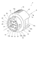
図1は、本実施の形態に係る車両用照明装置1を例示するための模式斜視図である。
図2は、図1において車両用照明装置1をA方向から見た模式図である。
図3は、図1における車両用照明装置1のB−B線方向の模式断面図である。
図4(a)〜(d)は、装着部11のフランジ14側の端面11aの位置、および、絶縁部13のフランジ14側の端面13aの位置を例示するための模式断面図である。
Hereinafter, embodiments will be illustrated with reference to the drawings. In the drawings, the same components are denoted by the same reference numerals and the detailed description will be appropriately omitted.
FIG. 1 is a schematic perspective view for illustrating a vehicle lighting device 1 according to the present embodiment.
FIG. 2 is a schematic view of the vehicle lighting device 1 in FIG. 1 as viewed from the A direction.
FIG. 3: is a schematic cross section of the BB line direction of the illuminating device 1 for vehicles in FIG.
4A to 4D are schematic cross-sectional views for illustrating the position of the end surface 11a of the mounting portion 11 on the flange 14 side and the position of the end surface 13a of the insulating portion 13 on the flange 14 side.

図1、図2、および図3に示すように、車両用照明装置1には、ソケット10、発光モジュール20、および給電部30が設けられている。
ソケット10は、収納部10aおよび放熱部10bを有する。
収納部10aは、装着部11、バヨネット12、および絶縁部13を有する。
As shown in FIGS. 1, 2 and 3, the vehicle lighting device 1 is provided with a socket 10, a light emitting module 20, and a power feeding unit 30.
The socket 10 has a storage portion 10a and a heat dissipation portion 10b.
The storage unit 10 a includes a mounting unit 11, a bayonet 12, and an insulating unit 13.

装着部11は、筒状を呈している。
装着部11は、例えば、円筒状を呈したものとすることができる。
装着部11は、フランジ14の放熱フィン16が設けられた側とは反対側に設けられている。
装着部11は、載置部15を囲んでいる。
車両用照明装置1の中心軸1aと直交する方向における装着部11の外形寸法は、フランジ14の外形寸法よりも小さい。
The mounting portion 11 has a tubular shape.
The mounting portion 11 can have, for example, a cylindrical shape.
The mounting portion 11 is provided on the side of the flange 14 opposite to the side on which the heat dissipating fins 16 are provided.
The mounting unit 11 surrounds the mounting unit 15.
The external dimension of the mounting portion 11 in the direction orthogonal to the central axis 1 a of the vehicle lighting device 1 is smaller than the external dimension of the flange 14.

バヨネット12は、装着部11の側面に設けられ、車両用照明装置1の外側に向けて突出している。
バヨネット12は、フランジ14と対峙している。
バヨネット12は、複数設けられている。
The bayonet 12 is provided on the side surface of the mounting portion 11 and protrudes outward of the vehicle lighting device 1.
The bayonet 12 faces the flange 14.
A plurality of bayonets 12 are provided.

車両用照明装置1を筐体101に装着する際には、装着部11のバヨネット12が設けられた部分が、筐体101に設けられた取付孔101aに挿入される。(図6を参照)。
そして、車両用照明装置1を回転させることで、筐体101に車両用照明装置1が保持されるようになっている。
すなわち、バヨネット12は、ツイストロックに用いられるものである。
When the vehicular illumination device 1 is mounted on the housing 101, the portion of the mounting portion 11 provided with the bayonet 12 is inserted into the mounting hole 101 a provided on the housing 101. (See Figure 6).
Then, the vehicle lighting device 1 is held by the casing 101 by rotating the vehicle lighting device 1.
That is, the bayonet 12 is used for twist lock.

絶縁部13は、装着部11の内部に設けられている。
ここで、図3および図4(a)に示すように、装着部11のフランジ14側の端面11aは、フランジ14の、放熱フィン16が設けられる側とは反対側の面14a上に位置するようにすることができる。
絶縁部13のフランジ14側の端面13aは、フランジ14の内部に位置するようにすることができる。
The insulating portion 13 is provided inside the mounting portion 11.
Here, as shown in FIGS. 3 and 4A, the end surface 11a of the mounting portion 11 on the flange 14 side is located on the surface 14a of the flange 14 on the side opposite to the side on which the radiation fins 16 are provided. You can do so.
The end surface 13 a on the flange 14 side of the insulating portion 13 can be positioned inside the flange 14.

図4(b)に示すように、装着部11のフランジ14側の端面11aは、フランジ14の面14a上に位置するようにすることができる。
絶縁部13のフランジ14側の端面13aは、フランジ14の面14a上に位置するようにすることができる。
As shown in FIG. 4 (b), the end face 11 a on the flange 14 side of the mounting portion 11 can be positioned on the face 14 a of the flange 14.
The end surface 13 a of the insulating portion 13 on the flange 14 side can be positioned on the surface 14 a of the flange 14.

図4(c)に示すように、装着部11のフランジ14側の端面11aは、フランジ14の内部に位置するようにすることができる。
絶縁部13のフランジ14側の端面13aは、フランジ14の内部に位置するようにすることができる。
As shown in FIG. 4C, the end face 11a on the flange 14 side of the mounting portion 11 can be positioned inside the flange 14.
The end surface 13 a on the flange 14 side of the insulating portion 13 can be positioned inside the flange 14.

図4(d)に示すように、装着部11のフランジ14側の端面11aは、フランジ14の内部に位置するようにすることができる。
絶縁部13のフランジ14側の端面13aは、フランジ14の面14a上に位置するようにすることができる。
As shown in FIG. 4 (d), the end face 11 a on the flange 14 side of the mounting portion 11 can be positioned inside the flange 14.
The end surface 13 a of the insulating portion 13 on the flange 14 side can be positioned on the surface 14 a of the flange 14.

また、装着部11のフランジ14側の端面11aと、フランジ14の面14aとの間に図示しない部材を設けることもできる。絶縁部13のフランジ14側の端面13aと、フランジ14の面14aとの間に図示しない部材を設けることもできる。
また、フランジ14の面14aに、装着部11および絶縁部13に向けて突出する突出部を設けることもできる。
Further, a member (not shown) may be provided between the end surface 11 a of the mounting portion 11 on the flange 14 side and the surface 14 a of the flange 14. A member (not shown) may be provided between the end face 13 a of the insulating portion 13 on the flange 14 side and the face 14 a of the flange 14.
In addition, the surface 14 a of the flange 14 may be provided with a protruding portion that protrudes toward the mounting portion 11 and the insulating portion 13.

すなわち、装着部11のフランジ14側の端面11aの位置および絶縁部13のフランジ14側の端面13aの位置は、フランジ14の、放熱フィン16が設けられた面14bの位置よりも発光モジュール20側にあればよい。   That is, the position of the end face 11 a of the mounting portion 11 on the flange 14 side and the position of the end face 13 a of the insulating portion 13 on the flange 14 side are closer to the light emitting module 20 than the position of the surface 14 b of the flange 14 provided with the radiation fins 16. It is good if

収納部10aは、装着部11、バヨネット12、および絶縁部13を一体成形して形成することもできるし、これらを接合して形成することもできる。
ただし、装着部11、バヨネット12、および絶縁部13を一体成形すれば、外力に対する耐性の向上、製造コストの低減などを図ることができる。
The storage portion 10a can be formed by integrally molding the mounting portion 11, the bayonet 12, and the insulating portion 13, or can be formed by bonding them.
However, if the mounting portion 11, the bayonet 12, and the insulating portion 13 are integrally formed, it is possible to improve the resistance to external forces, reduce the manufacturing cost, and the like.

収納部10aは、発光モジュール20を収納する機能と、給電端子31を絶縁する機能を有する。
そのため、装着部11、バヨネット12、および絶縁部13は、絶縁性材料から形成することが好ましい。
絶縁性材料は、例えば、樹脂などの有機材料、セラミックス(例えば、酸化アルミニウムや窒化アルミニウムなど)などの無機材料などとすることができる。
The storage unit 10 a has a function of storing the light emitting module 20 and a function of insulating the power supply terminal 31.
Therefore, the mounting portion 11, the bayonet 12, and the insulating portion 13 are preferably formed of an insulating material.
The insulating material can be, for example, an organic material such as a resin, or an inorganic material such as a ceramic (for example, aluminum oxide or aluminum nitride).

この場合、発光モジュール20において発生した熱を放熱部10bに伝えることを考慮して、装着部11、バヨネット12、および絶縁部13を絶縁性と高い熱伝導率を有する材料から形成することもできる。絶縁性と高い熱伝導率を有する材料は、例えば、セラミックス(例えば、酸化アルミニウムや窒化アルミニウムなど)、高熱伝導性樹脂などとすることができる。高熱伝導性樹脂は、例えば、PETやナイロン等の樹脂に、熱伝導率の高い酸化アルミニウムなどからなる繊維や粒子を混合させたものである。   In this case, the mounting portion 11, the bayonet 12, and the insulating portion 13 can be formed of a material having insulating properties and high thermal conductivity in consideration of transferring heat generated in the light emitting module 20 to the heat dissipation portion 10b. . The material having insulating properties and high thermal conductivity can be, for example, ceramics (eg, aluminum oxide, aluminum nitride, etc.), high thermal conductivity resins, and the like. The high thermal conductivity resin is, for example, a resin such as PET or nylon mixed with fibers or particles made of aluminum oxide or the like having high thermal conductivity.

なお、装着部11、バヨネット12、および絶縁部13は、金属などの導電性材料から形成することもできる。
ただし、給電端子31と絶縁部13との間に絶縁性材料からなる層を設けたり、絶縁部13のみを絶縁性材料から形成したりする必要がある。
In addition, the mounting part 11, the bayonet 12, and the insulation part 13 can also be formed from electroconductive materials, such as a metal.
However, it is necessary to provide a layer made of an insulating material between the feed terminal 31 and the insulating portion 13 or to form only the insulating portion 13 from the insulating material.

放熱部10bは、フランジ14、載置部15、放熱フィン16、および凸部17を有する。
フランジ14は、板状を呈している。
フランジ14は、例えば、円板状を呈したものとすることができる。
フランジ14の外側面と車両用照明装置1の中心軸1aとの間の距離は、バヨネット12の外側面と車両用照明装置1の中心軸1aとの間の距離よりも長い。すなわち、フランジ14の外側面は、バヨネット12の外側面よりも車両用照明装置1の外方に位置している。
The heat radiating portion 10 b has a flange 14, a mounting portion 15, a heat radiating fin 16, and a convex portion 17.
The flange 14 has a plate shape.
The flange 14 may have, for example, a disk shape.
The distance between the outer surface of the flange 14 and the central axis 1a of the vehicle lighting device 1 is longer than the distance between the outer surface of the bayonet 12 and the central axis 1a of the vehicle lighting device 1. That is, the outer side surface of the flange 14 is located more outward of the vehicle lighting device 1 than the outer side surface of the bayonet 12.

載置部15は、円筒状を呈したものとすることができる。載置部15は、フランジ14の、放熱フィン16が設けられる側とは反対側の面14aに設けられている。載置部15の側面には、凹部15aが設けられている。凹部15aの内部には、絶縁部13が設けられている。
載置部15の、フランジ14側とは反対側の面15bには、発光モジュール20が載置される。
The placement unit 15 can have a cylindrical shape. The mounting portion 15 is provided on the surface 14 a of the flange 14 opposite to the side on which the heat dissipating fins 16 are provided. A recess 15 a is provided on the side surface of the placement unit 15. An insulating portion 13 is provided inside the recess 15 a.
The light emitting module 20 is mounted on the surface 15 b of the mounting portion 15 on the side opposite to the flange 14 side.

放熱フィン16は、フランジ14の、載置部15が設けられる側とは反対側の面14bに設けられている。
放熱フィン16は、複数設けることができる。
複数の放熱フィン16は、互いに平行となるように設けることができる。放熱フィン16は、平板状を呈したものとすることができる。
発光モジュール20において発生した熱は、載置部15およびフランジ14を介して放熱フィン16に伝わる。放熱フィン16に伝わった熱は、放熱フィン16から外部に放出される。
The heat dissipating fins 16 are provided on the surface 14 b of the flange 14 opposite to the side on which the mounting portion 15 is provided.
A plurality of radiation fins 16 can be provided.
The plurality of heat radiation fins 16 can be provided in parallel with one another. The radiation fin 16 can be flat.
The heat generated in the light emitting module 20 is transmitted to the radiation fin 16 via the mounting portion 15 and the flange 14. The heat transferred to the radiation fin 16 is released from the radiation fin 16 to the outside.

凸部17は、フランジ14の放熱フィン16が設けられた面14bに設けられている。
凸部17は、ブロック状を呈したものとすることができる。
凸部17の外側面には、凹部17aが設けられている。凹部17aは、凸部17の外側面に開口している。
The convex portion 17 is provided on the surface 14 b of the flange 14 on which the heat dissipating fins 16 are provided.
The convex portion 17 can have a block shape.
The outer surface of the convex portion 17 is provided with a concave portion 17 a. The recess 17 a is open on the outer surface of the protrusion 17.

凸部17には、孔17bが設けられている。孔17bは、凸部17のフランジ14側とは反対側の端面と、フランジ14の、放熱フィン16が設けられる側とは反対側の面14aとの間を貫通している。
孔17bのフランジ14側には、給電端子31の端部が突出している。
孔17bのフランジ14側には、絶縁部13の一部分が露出している。すなわち、孔17bのフランジ14側の開口は、絶縁部13により塞がれている。
孔17bは、凹部17aと繋がっていない。
The convex portion 17 is provided with a hole 17 b. The hole 17 b passes between an end surface of the convex portion 17 on the opposite side to the flange 14 side and a surface 14 a of the flange 14 on the opposite side to the side on which the radiation fin 16 is provided.
The end of the feed terminal 31 protrudes on the flange 14 side of the hole 17 b.
A part of the insulating portion 13 is exposed on the flange 14 side of the hole 17 b. That is, the opening on the flange 14 side of the hole 17 b is closed by the insulating portion 13.
The hole 17b is not connected to the recess 17a.

孔17bには、シール部材105a(第2のシール部材の一例に相当する)を有するコネクタ105が挿入される。
そのため、孔17bの断面形状は、シール部材105aを有するコネクタ105の断面に適合したものとなっている。
また、車両用照明装置1の中心軸1aと直交する方向における孔17bの断面寸法は、コネクタ105の本体に設けられたシール部材105aの外形寸法よりも僅かに小さくなっている。そのため、シール部材105aを有するコネクタ105が孔17bに挿入された際には、孔17bが水密となるように密閉される。
A connector 105 having a seal member 105a (corresponding to an example of a second seal member) is inserted into the hole 17b.
Therefore, the cross-sectional shape of the hole 17b is adapted to the cross-section of the connector 105 having the seal member 105a.
Further, the cross-sectional dimension of the hole 17 b in the direction orthogonal to the central axis 1 a of the vehicular illumination device 1 is slightly smaller than the external dimension of the seal member 105 a provided in the main body of the connector 105. Therefore, when the connector 105 having the seal member 105a is inserted into the hole 17b, the hole 17b is sealed so as to be watertight.

放熱部10bは、フランジ14、載置部15、放熱フィン16、および凸部17を一体成形して形成することもできるし、これらを別々に形成して接合することもできる。
ただし、フランジ14、載置部15、放熱フィン16、および凸部17を一体成形すれば、放熱性の向上、外力に対する耐性の向上、製造コストの低減などを図ることができる。
The heat dissipating portion 10 b can be formed by integrally molding the flange 14, the mounting portion 15, the heat dissipating fin 16, and the convex portion 17, or they can be separately formed and joined.
However, if the flange 14, the mounting portion 15, the heat dissipating fin 16, and the convex portion 17 are integrally molded, it is possible to improve the heat dissipating property, improve the resistance to external force, reduce the manufacturing cost, and the like.

放熱部10bは、発光モジュール20を載置する機能と、発光モジュール20において発生した熱を外部に放出する機能を有する。
そのため、熱を放出する機能を考慮して、フランジ14、載置部15、放熱フィン16、および凸部17は、熱伝導率の高い材料から形成することが好ましい。熱伝導率の高い材料は、例えば、アルミニウムやアルミニウム合金などの金属、酸化アルミニウムや窒化アルミニウムなどのセラミックス、高熱伝導性樹脂などとすることができる。
The heat radiating portion 10 b has a function of mounting the light emitting module 20 and a function of releasing the heat generated in the light emitting module 20 to the outside.
Therefore, in consideration of the function of releasing heat, it is preferable to form the flange 14, the mounting portion 15, the radiation fin 16, and the convex portion 17 from a material having high thermal conductivity. The material having a high thermal conductivity can be, for example, a metal such as aluminum or aluminum alloy, a ceramic such as aluminum oxide or aluminum nitride, or a high thermal conductivity resin.

この場合、収納部10aの材料と、放熱部10bの材料は、互いに異なるものとすることができる。
例えば、収納部10aを樹脂などの絶縁性材料から形成し、放熱部10bを金属(例えば、アルミニウム合金など)などの熱伝導率の高い材料から形成することができる。
In this case, the material of the storage portion 10a and the material of the heat dissipation portion 10b can be different from each other.
For example, the storage portion 10a can be formed of an insulating material such as a resin, and the heat dissipation portion 10b can be formed of a material having a high thermal conductivity such as a metal (for example, an aluminum alloy or the like).

ここで、装着部11は、フランジ14の、放熱フィン16が設けられる側とは反対側に設けられている。
また、装着部11は、載置部15を囲んでいる。
しかしながら、装着部11は、フランジ14、放熱フィン16、および凸部17を囲んでいない。
そのため、光モジュール20において発生した熱を、熱伝導率の高い材料から形成されたフランジ14、放熱フィン16、および凸部17を介して外部に効率よく放出することができる。すなわち、車両用照明装置1の放熱性を向上させることができる。
Here, the mounting portion 11 is provided on the side of the flange 14 opposite to the side where the radiation fin 16 is provided.
Further, the mounting unit 11 surrounds the mounting unit 15.
However, the mounting portion 11 does not surround the flange 14, the radiation fin 16, and the protrusion 17.
Therefore, the heat generated in the optical module 20 can be efficiently released to the outside through the flange 14 formed of a material having a high thermal conductivity, the radiation fin 16, and the convex portion 17. That is, the heat dissipation of the vehicle lighting device 1 can be improved.

また、放熱部10bは、収納部10aと接続される。収納部10aの絶縁部13は、放熱部10bの凹部15aの内部に挿入される。放熱部10bの載置部15は、収納部10aの装着部11の内部に挿入される。
この場合、収納部10aと放熱部10bは、嵌め合わされるようにしてもよいし、接着剤などを用いて接合してもよいし、インサート成型により収納部10aと放熱部10bを接合してもよいし、加熱溶着により収納部10aと放熱部10bを接合してもよい。
The heat dissipation unit 10 b is connected to the storage unit 10 a. The insulating portion 13 of the storage portion 10a is inserted into the recess 15a of the heat dissipation portion 10b. The mounting portion 15 of the heat radiating portion 10 b is inserted into the inside of the mounting portion 11 of the housing portion 10 a.
In this case, the storage portion 10a and the heat dissipation portion 10b may be fitted, may be joined using an adhesive or the like, or the storage portion 10a and the heat dissipation portion 10b may be joined by insert molding. Alternatively, the housing portion 10a and the heat radiating portion 10b may be joined by heat welding.

ここで、収納部10aと放熱部10bを接続すると、収納部10aと放熱部10bの間に界面が形成される。
収納部10aと放熱部10bの間に界面が形成されていると、界面から水分が侵入するおそれがある。
この場合、収納部10aと放熱部10bを接着などすれば、界面から水分が侵入するのを抑制することができる。
しかしながら、界面を完全に封止することは難しい。
また、自動車に設けられる車両用照明装置1の場合には、使用環境の温度が、−40℃〜85℃となる。そのため、当初は水密であったとしても、熱膨張率の差により発生した熱応力により、時間の経過とともに水密性が低下するおそれがある。
Here, when the storage portion 10 a and the heat dissipation portion 10 b are connected, an interface is formed between the storage portion 10 a and the heat dissipation portion 10 b.
If an interface is formed between the storage portion 10a and the heat dissipation portion 10b, there is a possibility that moisture may infiltrate from the interface.
In this case, if the storage portion 10a and the heat dissipation portion 10b are bonded, it is possible to suppress the entry of water from the interface.
However, it is difficult to completely seal the interface.
Moreover, in the case of the illuminating device 1 for vehicles provided in a motor vehicle, the temperature of use environment turns into -40 degreeC-85 degreeC. Therefore, even if it is water-tight at first, there is a possibility that the water-tightness may deteriorate with the passage of time due to the thermal stress generated due to the difference in the thermal expansion coefficient.

そこで、本実施の形態においては、装着部11のフランジ14側の端面11aの位置および絶縁部13のフランジ14側の端面13aの位置が、フランジ14の面14bの位置よりも発光モジュール20側にあるようになっている。
また、車両用照明装置1の中心軸1aと直交する方向における装着部11の外形寸法は、フランジ14の外形寸法よりも小さくなっている。
そのため、図3に示すように、装着部11とフランジ14の間の界面は、シール部材104(第1のシール部材の一例に相当する)により封止することができる。
Therefore, in the present embodiment, the position of the end face 11a of the mounting portion 11 on the flange 14 side and the position of the end face 13a of the insulating portion 13 on the flange 14 side are closer to the light emitting module 20 than the position of the face 14b of the flange 14 It is supposed to be.
Further, the outer dimension of the mounting portion 11 in the direction orthogonal to the central axis 1 a of the vehicle lighting device 1 is smaller than the outer dimension of the flange 14.
Therefore, as shown in FIG. 3, the interface between the mounting portion 11 and the flange 14 can be sealed by the seal member 104 (corresponding to an example of the first seal member).

なお、孔17bのフランジ14側には、絶縁部13の一部分が露出している。すなわち、孔17bの内部には、絶縁部13とフランジ14の間の界面が露出している。
しかしながら、孔17bには、シール部材105aを有するコネクタ105が挿入される。
そのため、シール部材105aを有するコネクタ105が孔17bに挿入された際には、孔17bが水密となるように密閉される。
その結果、絶縁部13とフランジ14の間の界面から水分が侵入するのを抑制することができる。
A part of the insulating portion 13 is exposed on the flange 14 side of the hole 17 b. That is, the interface between the insulating portion 13 and the flange 14 is exposed inside the hole 17 b.
However, the connector 105 having the seal member 105a is inserted into the hole 17b.
Therefore, when the connector 105 having the seal member 105a is inserted into the hole 17b, the hole 17b is sealed so as to be watertight.
As a result, it is possible to suppress the entry of moisture from the interface between the insulating portion 13 and the flange 14.

なお、水分は、主に、車両用灯具100の筐体101の外側にある。そのため、筐体101の内部からシール部材104の内側に侵入する水分はほとんどない。
以上に説明したように、本実施の形態に係る車両用照明装置1によれば、収納部10aと放熱部10bを接続するようにしても界面から水分が侵入するのを抑制することができる。
The water is mainly located outside the housing 101 of the vehicular lamp 100. Therefore, almost no moisture intrudes from the inside of the housing 101 into the inside of the seal member 104.
As described above, according to the vehicle lighting device 1 of the present embodiment, it is possible to suppress the entry of moisture from the interface even when the storage portion 10a and the heat dissipation portion 10b are connected.

また、図1および図3に示すように、発光モジュール20は、載置部15のフランジ14側とは反対側の面15bに設けられている。
発光モジュール20は、基板21、発光素子22、制御素子23、および制御素子24を有する。
基板21は、載置部15の面15bの上に設けられている。
基板21は、平板状を呈している。基板21の表面には、配線パターンが設けられている。
基板21の材料や構造には特に限定はない。例えば、基板21は、セラミックス(例えば、酸化アルミニウムや窒化アルミニウムなど)などの無機材料、紙フェノールやガラスエポキシなどの有機材料などから形成することができる。また、基板21は、金属板の表面を絶縁性材料で被覆したものであってもよい。なお、金属板の表面を絶縁性材料で被覆する場合には、絶縁性材料は、有機材料からなるものであってもよいし、無機材料からなるものであってもよい。
Further, as shown in FIG. 1 and FIG. 3, the light emitting module 20 is provided on the surface 15 b of the mounting portion 15 on the opposite side to the flange 14 side.
The light emitting module 20 includes a substrate 21, a light emitting element 22, a control element 23, and a control element 24.
The substrate 21 is provided on the surface 15 b of the placement unit 15.
The substrate 21 has a flat plate shape. A wiring pattern is provided on the surface of the substrate 21.
There are no particular limitations on the material and structure of the substrate 21. For example, the substrate 21 can be formed of an inorganic material such as ceramics (for example, aluminum oxide or aluminum nitride) or an organic material such as paper phenol or glass epoxy. Further, the substrate 21 may be one in which the surface of a metal plate is covered with an insulating material. When the surface of the metal plate is coated with an insulating material, the insulating material may be made of an organic material or an inorganic material.

この場合、発光素子22の発熱量が多い場合には、放熱の観点から熱伝導率の高い材料を用いて基板21を形成することが好ましい。熱伝導率の高い材料としては、例えば、酸化アルミニウムや窒化アルミニウムなどのセラミックス、高熱伝導性樹脂、金属板の表面を絶縁性材料で被覆したものなどを例示することができる。
また、基板21は、単層であってもよいし、多層であってもよい。
In this case, when the amount of heat generation of the light emitting element 22 is large, it is preferable to form the substrate 21 using a material having a high thermal conductivity from the viewpoint of heat dissipation. Examples of materials having high thermal conductivity include ceramics such as aluminum oxide and aluminum nitride, high thermal conductivity resins, and materials obtained by coating the surface of a metal plate with an insulating material.
The substrate 21 may be a single layer or a multilayer.

発光素子22は、基板21の上に設けられている。発光素子22は、基板21の表面に設けられた配線パターンと電気的に接続されている。
発光素子22は、例えば、発光ダイオード、有機発光ダイオード、レーザダイオードなどとすることができる。
The light emitting element 22 is provided on the substrate 21. The light emitting element 22 is electrically connected to a wiring pattern provided on the surface of the substrate 21.
The light emitting element 22 can be, for example, a light emitting diode, an organic light emitting diode, a laser diode or the like.

発光素子22の形式には特に限定はない。
発光素子22は、例えば、PLCC(Plastic Leaded Chip Carrier)型などの表面実装型の発光素子とすることができる。
発光素子22は、例えば、砲弾型などのリード線を有する発光素子とすることもできる。
There is no particular limitation on the type of the light emitting element 22.
The light emitting element 22 can be, for example, a surface mounted light emitting element such as a PLCC (Plastic Leaded Chip Carrier) type.
The light emitting element 22 can also be a light emitting element having a lead wire of, for example, a shell type.

また、発光素子22は、COB(Chip On Board)により実装されるものとすることもできる。
COBにより実装される発光素子22とする場合には、チップ状の発光素子22と、発光素子22と配線パターンを電気的に接続する配線と、発光素子22と配線を囲む枠状の部材と、枠状の部材の内部に設けられた封止部などを基板21の上に設けることができる。
The light emitting element 22 can also be mounted by COB (Chip On Board).
In the case of using the light emitting element 22 mounted by COB, the chip-like light emitting element 22, a wire electrically connecting the light emitting element 22 and the wiring pattern, and a frame-like member surrounding the light emitting element 22 and the wire A sealing portion or the like provided inside the frame-like member can be provided on the substrate 21.

この場合、封止部には、蛍光体を含めることができる。
蛍光体は、例えば、YAG系蛍光体(イットリウム・アルミニウム・ガーネット系蛍光体)とすることができる。
例えば、発光素子22が青色発光ダイオード、蛍光体がYAG系蛍光体である場合には、発光素子22から出射した青色の光によりYAG系蛍光体が励起され、YAG系蛍光体から黄色の蛍光が放射される。そして、青色の光と黄色の光が混ざり合うことで、白色の光が車両用照明装置1から出射される。なお、蛍光体の種類や発光素子22の種類は、例示をしたものに限定されるわけではない。蛍光体の種類や発光素子22の種類は、車両用照明装置1の用途などに応じて所望の発光色が得られるように適宜変更することができる。
In this case, the sealing portion can contain a phosphor.
The phosphor can be, for example, a YAG-based phosphor (yttrium-aluminum-garnet-based phosphor).
For example, when the light emitting element 22 is a blue light emitting diode and the fluorescent substance is a YAG fluorescent substance, the blue light emitted from the light emitting element 22 excites the YAG fluorescent substance and yellow fluorescent light from the YAG fluorescent substance It is emitted. Then, by mixing blue light and yellow light, white light is emitted from the vehicle lighting device 1. In addition, the kind of fluorescent substance and the kind of light emitting element 22 are not necessarily limited to what was illustrated. The type of the phosphor and the type of the light emitting element 22 can be appropriately changed so as to obtain a desired emission color according to the application of the vehicle lighting device 1 and the like.

発光素子22の光の出射面である上面は、車両用照明装置1の正面側に向けられており、主に、車両用照明装置1の正面側に向けて光を出射する。
発光素子22の数、大きさ、配置などは、例示をしたものに限定されるわけではなく、車両用照明装置1の大きさや用途などに応じて適宜変更することができる。
The upper surface which is a light emission surface of the light emitting element 22 is directed to the front side of the vehicular illumination device 1 and mainly emits light toward the front side of the vehicular illumination device 1.
The number, the size, the arrangement, and the like of the light emitting elements 22 are not limited to those illustrated, and can be appropriately changed according to the size, the application, and the like of the vehicular illumination device 1.

制御素子23は、基板21の上に設けられている。制御素子23は、基板21の表面に設けられた配線パターンと電気的に接続されている。
制御素子23は、例えば、発光素子22に流れる電流を制御するものとすることができる。
The control element 23 is provided on the substrate 21. The control element 23 is electrically connected to a wiring pattern provided on the surface of the substrate 21.
The control element 23 can control, for example, the current flowing to the light emitting element 22.

発光素子22の順方向電圧特性には、ばらつきがあるので、アノード端子と、グランド端子と、の間の印加電圧を一定にすると、発光素子22の明るさ(光束、輝度、光度、照度)にばらつきが生じる。そのため、発光素子22の明るさが所定の範囲内に収まるように、制御素子23により、発光素子22に流れる電流の値が所定の範囲内となるようにする。   Since the forward voltage characteristics of the light emitting element 22 have variations, when the applied voltage between the anode terminal and the ground terminal is constant, the brightness (light flux, luminance, light intensity, illuminance) of the light emitting element 22 Variations occur. Therefore, the value of the current flowing through the light emitting element 22 is made to be within the predetermined range by the control element 23 so that the brightness of the light emitting element 22 falls within the predetermined range.

制御素子23は、例えば、抵抗器とすることができる。制御素子23は、例えば、表面実装型の抵抗器、リード線を有する抵抗器(酸化金属皮膜抵抗器)、スクリーン印刷法などを用いて形成された膜状の抵抗器などとすることができる。
なお、図1および図3に例示をした制御素子23は、表面実装型の抵抗器である。
The control element 23 can be, for example, a resistor. The control element 23 can be, for example, a surface mount type resistor, a resistor having a lead wire (metal oxide film resistor), a film-like resistor formed by using a screen printing method, or the like.
The control element 23 illustrated in FIGS. 1 and 3 is a surface mount type resistor.

この場合、制御素子23の抵抗値を変化させることで、発光素子22に流れる電流の値が所定の範囲内となるようにすることができる。
例えば、制御素子23が膜状の抵抗器の場合には、複数の制御素子23毎に一部を除去して図示しない除去部をそれぞれに形成する。そして、除去部の大きさなどにより、複数の制御素子23毎に抵抗値を変化させる。この場合、制御素子23の一部を除去すれば、抵抗値は増加することになる。制御素子23の一部の除去は、例えば、制御素子23にレーザ光を照射することで行うことができる。
制御素子23の数、大きさ、配置などは、例示をしたものに限定されるわけではなく、発光素子22の数や仕様などに応じて適宜変更することができる。
In this case, by changing the resistance value of the control element 23, the value of the current flowing through the light emitting element 22 can be made to fall within a predetermined range.
For example, in the case where the control element 23 is a film resistor, a part of each of the plurality of control elements 23 is removed to form a removal portion (not shown). Then, the resistance value is changed for each of the plurality of control elements 23 according to the size of the removing unit or the like. In this case, if part of the control element 23 is removed, the resistance value will increase. The removal of part of the control element 23 can be performed, for example, by irradiating the control element 23 with laser light.
The number, the size, the arrangement, and the like of the control elements 23 are not limited to those illustrated, but can be appropriately changed according to the number of the light emitting elements 22, the specification, and the like.

制御素子24は、基板21の上に設けられている。制御素子24は、基板21の表面に設けられた配線パターンと電気的に接続されている。
制御素子24は、逆方向電圧が発光素子22に印加されないようにするため、および、逆方向からのパルスノイズが発光素子22に印加されないようにするために設けられている。
制御素子24は、例えば、ダイオードとすることができる。制御素子24は、例えば、表面実装型のダイオードや、リード線を有するダイオードなどとすることができる。
図1に例示をした制御素子24は、表面実装型のダイオードである。
The control element 24 is provided on the substrate 21. The control element 24 is electrically connected to a wiring pattern provided on the surface of the substrate 21.
The control element 24 is provided to prevent reverse voltage from being applied to the light emitting element 22 and to prevent pulse noise from the reverse direction from being applied to the light emitting element 22.
The control element 24 can be, for example, a diode. The control element 24 can be, for example, a surface mount diode or a diode having a lead.
The control element 24 illustrated in FIG. 1 is a surface mounted diode.

その他、発光素子22の断線の検出や、誤点灯防止などのために、プルダウン抵抗を設けることもできる。
また、配線パターンや膜状の抵抗器などを覆う被覆部を設けることもできる。被覆部は、例えば、ガラス材料を含むものとすることができる。
In addition, a pull-down resistor can be provided to detect disconnection of the light emitting element 22 or to prevent erroneous lighting.
In addition, a covering portion that covers the wiring pattern, the film-like resistor, and the like can be provided. The covering portion can include, for example, a glass material.

給電部30は、複数の給電端子31を有する。
複数の給電端子31は、所定の方向に並べて設けることができる。
複数の給電端子31は、ソケット10(絶縁部13)の内部に設けられている。
複数の給電端子31は、絶縁部13の内部を延びている。
複数の給電端子31の一方の端部は、発光モジュール20と電気的に接続されている。 複数の給電端子31の一方の端部は、絶縁部13の、フランジ14側とは反対側の端面から突出し、基板21に設けられた配線パターンと電気的に接続されている。
複数の給電端子31の他方の端部は、絶縁部13のフランジ14側の端面13aから突出している。複数の給電端子31の他方の端部は、孔17bの内部に露出している。
The feed unit 30 has a plurality of feed terminals 31.
The plurality of feed terminals 31 can be provided side by side in a predetermined direction.
The plurality of power supply terminals 31 are provided inside the socket 10 (insulation unit 13).
The plurality of feed terminals 31 extend inside the insulating portion 13.
One end of each of the plurality of power supply terminals 31 is electrically connected to the light emitting module 20. One end of each of the plurality of feed terminals 31 protrudes from the end face of the insulating portion 13 on the opposite side to the flange 14 side, and is electrically connected to the wiring pattern provided on the substrate 21.
The other end of each of the plurality of feed terminals 31 protrudes from an end face 13 a on the flange 14 side of the insulating portion 13. The other ends of the plurality of feed terminals 31 are exposed to the inside of the hole 17 b.

なお、給電端子31の数、形状などは例示をしたものに限定されるわけではなく、適宜変更することができる。
また、給電部30は、図示しない基板や、回路部品(例えば、コンデンサや抵抗など)などを備えたものとすることもできる。なお、図示しない基板や回路部品などは、例えば、収納部10aの内部や放熱部10bの内部などに設けることができる。
Note that the number, shape, and the like of the power supply terminals 31 are not limited to those illustrated, and can be changed as appropriate.
Also, the power supply unit 30 may be provided with a substrate (not shown), circuit components (for example, a capacitor, a resistor, etc.) and the like. In addition, the board | substrate, a circuit component, etc. which are not shown in figure can be provided in the inside of the accommodating part 10a, the inside of the thermal radiation part 10b, etc., for example.

図5は、他の実施形態に係る装着部11、絶縁部13、および載置部15を例示するための模式断面図である。
図5に示すように、装着部11の内側面(内壁)には凸部11bを設けることができる。載置部15の外側面(外壁)の、凸部11bに対応する位置には、凹部15cを設けることができる。凸部11bは、凹部15cに嵌め合わされるようにすることができる。
この様にすれば、装着部11と載置部15の間の抜け強度を高めることができる。
なお、装着部11の内側面(内壁)に凹部を設け、載置部15の外側面(外壁)に凸部を設けるようにしてもよい。
FIG. 5 is a schematic cross-sectional view for illustrating the mounting portion 11, the insulating portion 13, and the mounting portion 15 according to another embodiment.
As shown in FIG. 5, a convex portion 11 b can be provided on the inner side surface (inner wall) of the mounting portion 11. The recessed part 15c can be provided in the position corresponding to the convex part 11b of the outer surface (outer wall) of the mounting part 15. As shown in FIG. The convex portion 11 b can be fitted into the concave portion 15 c.
In this way, the pull-out strength between the mounting portion 11 and the mounting portion 15 can be increased.
A recess may be provided on the inner side surface (inner wall) of the mounting portion 11 and a protrusion may be provided on the outer side surface (outer wall) of the mounting portion 15.

絶縁部13の内側面(内壁)には凸部13bを設けることができる。載置部15の外側面(外壁)の、凸部13bに対応する位置には、凹部15dを設けることができる。凸部13bは、凹部15dに嵌め合わされるようにすることができる。
この様にすれば、絶縁部13と載置部15の間の抜け強度を高めることができる。
なお、絶縁部13の内側面(内壁)に凹部を設け、載置部15の外側面(外壁)に凸部を設けるようにしてもよい。
The convex portion 13 b can be provided on the inner side surface (inner wall) of the insulating portion 13. The recessed part 15d can be provided in the position corresponding to the convex part 13b of the outer surface (outer wall) of the mounting part 15. As shown in FIG. The protrusion 13 b can be fitted into the recess 15 d.
In this manner, the strength of the removal between the insulating portion 13 and the placement portion 15 can be increased.
A recess may be provided on the inner side surface (inner wall) of the insulating portion 13 and a protrusion may be provided on the outer side surface (outer wall) of the mounting portion 15.

凸部11b、凹部15c、凸部13b、および凹部15dの数、配設位置、形状、大きさなどは例示をしたものに限定されるわけではなく、適宜変更することができる。
例えば、凸部11bは、装着部11の内側面(内壁)に連続的に設けられていてもよいし、部分的に設けられていてもよい。凸部13bは、絶縁部13の内側面(内壁)に連続的に設けられていてもよいし、部分的に設けられていてもよい。凹部15cおよび凹部15dは、載置部15の外側面(外壁)に連続的に設けられていてもよいし、部分的に設けられていてもよい。また、凸部11bおよび凸部13bが一体に設けられていてもよい。凹部15cおよび凹部15dが一体に設けられていてもよい。
また、凸部11bと凸部13bは、配設位置、形状、大きさなどが同じであってもよいし、異なっていてもよい。凹部15cと凹部15dは、配設位置、形状、大きさなどが同じであってもよいし、異なっていてもよい。
The number of the convex portions 11b, the concave portions 15c, the convex portions 13b, and the concave portions 15d, the arrangement position, the shape, the size, and the like are not limited to those illustrated, and can be appropriately changed.
For example, the convex portion 11 b may be continuously provided on the inner side surface (inner wall) of the mounting portion 11 or may be partially provided. The convex portion 13 b may be continuously provided on the inner side surface (inner wall) of the insulating portion 13 or may be partially provided. The recess 15 c and the recess 15 d may be provided continuously on the outer surface (outer wall) of the mounting portion 15 or may be provided partially. Also, the convex portion 11 b and the convex portion 13 b may be integrally provided. The recess 15 c and the recess 15 d may be integrally provided.
The convex portion 11 b and the convex portion 13 b may have the same arrangement position, shape, size, etc., or may be different. The recess 15 c and the recess 15 d may have the same arrangement position, shape, size, etc., or may be different.

次に、本実施の形態に係る車両用灯具100について例示する。
本実施の形態に係る車両用灯具100としては、例えば、自動車に設けられるフロントコンビネーションライト(例えば、デイタイムランニングランプ(DRL;Daylight Running Lamp)、ポジションランプ、ターンシグナルランプなどが適宜組み合わされたもの)や、リアコンビネーションライト(例えば、ストップランプ、テールランプ、ターンシグナルランプ、バックランプ、フォグランプなどが適宜組み合わされたもの)などを例示することができる。
Next, the vehicle lamp 100 according to the present embodiment will be illustrated.
As the vehicle lamp 100 according to the present embodiment, for example, a front combination light (for example, a daytime running lamp (DRL), a position lamp, a turn signal lamp, etc. appropriately combined) provided in a car And rear combination lights (for example, a combination of a stop lamp, a tail lamp, a turn signal lamp, a back lamp, a fog lamp and the like as appropriate) and the like.

なお、以下においては、一例として、車両用灯具100が自動車に設けられるフロントコンビネーションライトである場合を説明する。ただし、車両用灯具100は、自動車に設けられるフロントコンビネーションライトに限定されるわけではない。車両用灯具100は、自動車や鉄道車両などに設けられる車両用灯具であればよい。   In addition, below, the case where the vehicle lamp 100 is a front combination light provided in a motor vehicle is demonstrated as an example. However, the vehicular lamp 100 is not limited to the front combination light provided in a car. The vehicular lamp 100 may be a vehicular lamp provided in a car, a railway vehicle, or the like.

図6は、本実施の形態に係る車両用灯具100を例示するための模式部分断面図である。
図6に示すように、車両用灯具100には、車両用照明装置1、筐体101、カバー102、光学要素部103、シール部材104、およびコネクタ105が設けられている。
FIG. 6 is a schematic partial cross-sectional view for illustrating the vehicle lamp 100 according to the present embodiment.
As shown in FIG. 6, the vehicular lamp 100 is provided with a vehicular illumination device 1, a housing 101, a cover 102, an optical element portion 103, a seal member 104, and a connector 105.

筐体101は、一方の端部側が開口した箱状を呈している。筐体101は、例えば、光を透過しない樹脂などから形成することができる。
筐体101の底面には、装着部11のバヨネット12が設けられた部分が挿入される取付孔101aが設けられている。
取付孔101aの周縁には、装着部11に設けられたバヨネット12が挿入される凹部が設けられている。
なお、筐体101に取付孔101aが直接設けられる場合を例示したが、取付孔101aを有する取付部材が筐体101に設けられていてもよい。
The housing 101 has a box shape with one end opened. The housing 101 can be formed of, for example, a resin that does not transmit light.
The bottom of the housing 101 is provided with a mounting hole 101a into which the portion of the mounting portion 11 provided with the bayonet 12 is inserted.
At the periphery of the mounting hole 101a, a recess is provided in which the bayonet 12 provided in the mounting portion 11 is inserted.
In addition, although the case where the attachment hole 101a was directly provided in the housing | casing 101 was illustrated, the attachment member which has the attachment hole 101a may be provided in the housing | casing 101. FIG.

車両用照明装置1を車両用灯具100に取り付ける際には、装着部11のバヨネット12が設けられた部分を取付孔101aに挿入し、車両用照明装置1を回転させる。すると、取付孔101aの周縁に設けられた凹部にバヨネット12が保持される。
この様な取り付け方法は、ツイストロックと呼ばれている。
When attaching the vehicular illumination device 1 to the vehicular lamp 100, the portion of the attachment portion 11 provided with the bayonet 12 is inserted into the attachment hole 101a, and the vehicular illumination device 1 is rotated. Then, the bayonet 12 is hold | maintained at the recessed part provided in the periphery of the attachment hole 101a.
Such a mounting method is called twist lock.

カバー102は、筐体101の開口を塞ぐようにして設けられている。カバー102は、透光性を有する樹脂などから形成することができる。
カバー102は、レンズなどの機能を有するものとすることもできる。
The cover 102 is provided to close the opening of the housing 101. The cover 102 can be formed of a translucent resin or the like.
The cover 102 can also have a function such as a lens.

光学要素部103には、車両用照明装置1から出射した光が入射する。
光学要素部103は、車両用照明装置1から出射した光の反射、拡散、導光、集光、所定の配光パターンの形成などを行う。
例えば、図6に例示をした光学要素部103はリフレクタである。この場合、光学要素部103は、車両用照明装置1から出射した光を反射して、所定の配光パターンが形成されるようにする。
光学要素部103がリフレクタである場合には、光学要素部103は、筐体101の内部に、取付孔101aの中心軸と同芯となるように設けることができる。
The light emitted from the vehicle lighting device 1 is incident on the optical element portion 103.
The optical element unit 103 performs reflection, diffusion, light guiding, condensing, formation of a predetermined light distribution pattern, and the like of light emitted from the vehicle lighting device 1.
For example, the optical element unit 103 illustrated in FIG. 6 is a reflector. In this case, the optical element unit 103 reflects the light emitted from the vehicular illumination device 1 so that a predetermined light distribution pattern is formed.
When the optical element portion 103 is a reflector, the optical element portion 103 can be provided inside the housing 101 so as to be concentric with the central axis of the mounting hole 101 a.

シール部材104は、フランジ14と筐体101の間に設けられている。
シール部材104は、環状を呈するものとすることができる。
シール部材104は、ゴムやシリコーン樹脂などの弾性を有する材料から形成することができる。
The seal member 104 is provided between the flange 14 and the housing 101.
The seal member 104 can have an annular shape.
The seal member 104 can be formed of an elastic material such as rubber or silicone resin.

車両用照明装置1が車両用灯具100に取り付けられた際には、シール部材104は、フランジ14と筐体101との間に挟まれる。そのため、シール部材104により、筐体101の内部空間が密閉される。
また、前述したように、装着部11とフランジ14の間の界面が、シール部材104により封止される。
また、シール部材104の弾性力により、バヨネット12が筐体101に押し付けられる。そのため、車両用照明装置1が、筐体101から脱離するのを抑制することができる。
When the vehicle lighting device 1 is attached to the vehicle lamp 100, the seal member 104 is sandwiched between the flange 14 and the housing 101. Therefore, the internal space of the housing 101 is sealed by the sealing member 104.
Further, as described above, the interface between the mounting portion 11 and the flange 14 is sealed by the seal member 104.
Further, the bayonet 12 is pressed against the housing 101 by the elastic force of the seal member 104. Therefore, the vehicle lighting device 1 can be prevented from being detached from the housing 101.

コネクタ105は、孔17bの内部に露出している複数の給電端子31の端部に嵌め合わされる。
コネクタ105には、図示しない電源などが電気的に接続されている。
そのため、コネクタ105を給電端子31の端部に嵌め合わせることで、図示しない電源などと、発光素子22とが電気的に接続される。
また、コネクタ105は、段差部分を有している。そして、シール部材105aが、段差部分に取り付けられている(図3を参照)。
シール部材105aは、孔17bの内部に水が侵入するのを防ぐために設けられている。
シール部材105aを有するコネクタ105が孔17bに挿入された際には、孔17bが水密となるように密閉される。
The connector 105 is fitted to the end of the plurality of feed terminals 31 exposed inside the hole 17 b.
The connector 105 is electrically connected to a power supply (not shown) and the like.
Therefore, by fitting the connector 105 to the end portion of the power supply terminal 31, the power supply or the like (not shown) and the light emitting element 22 are electrically connected.
Further, the connector 105 has a stepped portion. And the sealing member 105a is attached to the level | step-difference part (refer FIG. 3).
The sealing member 105a is provided to prevent water from intruding into the inside of the hole 17b.
When the connector 105 having the seal member 105a is inserted into the hole 17b, the hole 17b is sealed so as to be watertight.

シール部材105aは、環状を呈するものとすることができる。
シール部材105aは、ゴムやシリコーン樹脂などの弾性を有する材料から形成することができる。
コネクタ105は、例えば、接着剤などを用いてソケット10側の要素に接合することもできる。
The seal member 105a can have an annular shape.
The seal member 105a can be formed of an elastic material such as rubber or silicone resin.
The connector 105 can also be joined to the element on the socket 10 side using, for example, an adhesive.

以上、本発明のいくつかの実施形態を例示したが、これらの実施形態は、例として提示したものであり、発明の範囲を限定することは意図していない。これら新規な実施形態は、その他の様々な形態で実施されることが可能であり、発明の要旨を逸脱しない範囲で、種々の省略、置き換え、変更などを行うことができる。これら実施形態やその変形例は、発明の範囲や要旨に含まれるとともに、特許請求の範囲に記載された発明とその均等の範囲に含まれる。また、前述の各実施形態は、相互に組み合わせて実施することができる。   While certain embodiments of the present invention have been illustrated, these embodiments have been presented by way of example only, and are not intended to limit the scope of the invention. These novel embodiments can be implemented in other various forms, and various omissions, replacements, changes, and the like can be made without departing from the scope of the invention. These embodiments and modifications thereof are included in the scope and the gist of the invention, and are included in the invention described in the claims and the equivalent scope thereof. In addition, the embodiments described above can be implemented in combination with each other.

1 車両用照明装置、10 ソケット、10a 収納部、10b 放熱部、11 装着部、12 バヨネット、13 絶縁部、14 フランジ、14a 面、14b 面、15 載置部、16 放熱フィン、17 凸部、17b 孔、20 発光モジュール、21 基板、22 発光素子、30 給電部、31 給電端子、100 車両用灯具、101 筐体、104 シール部材、105 コネクタ、105a シール部材   DESCRIPTION OF SYMBOLS 1 Vehicle illumination device, 10 socket, 10a storage part, 10b heat dissipation part, 11 mounting part, 12 bayonet, 13 insulation part, 14 flange, 14a surface, 14b surface, 15 mounting part, 16 radiation fin, 17 convex part, Reference Signs List 17 b hole, 20 light emitting module, 21 substrate, 22 light emitting element, 30 power feeding unit, 31 power feeding terminal, 100 vehicle lamp, 101 housing, 104 seal member, 105 connector, 105 a seal member

Claims (4)

板状を呈するフランジと、前記フランジの一方の面に設けられた放熱フィンと、前記フランジの前記放熱フィンが設けられた側とは反対側の面に設けられた載置部と、を有する放熱部と;
前記フランジの前記放熱フィンが設けられた側とは反対側に設けられ、前記載置部を囲む装着部と、前記装着部の側面に設けられたバヨネットと、を有し、前記放熱部の材料と異なる材料から形成された収納部と;
前記載置部の前記フランジ側とは反対側の端面に設けられ、発光素子を有する発光モジュールと;
を具備した車両用照明装置と;
前記装着部の前記バヨネットが設けられた部分が挿入される孔を有する筐体と;
前記筐体と、前記フランジとの間に設けられ、前記筐体と、前記フランジの前記放熱フィンが設けられた側とは反対側の面と、に接触する第1のシール部材と;
を具備し、
前記車両用照明装置の中心軸と直交する方向における前記装着部の外形寸法は、前記フランジの外形寸法よりも小さい車両用灯具
Heat dissipation having a plate-like flange, a radiation fin provided on one surface of the flange, and a mounting portion provided on the surface of the flange opposite to the side on which the radiation fin is provided Department and
The flange has a mounting portion provided on the side opposite to the side on which the heat dissipating fins are provided and surrounding the mounting portion, and a bayonet provided on the side surface of the mounting portion, and the material of the heat dissipating portion And storage compartments made of different materials;
A light emitting module having a light emitting element provided on an end face of the mounting portion opposite to the flange side;
A vehicle lighting device provided with a;
A housing having a hole into which the portion of the mounting portion provided with the bayonet is inserted;
A first seal member provided between the housing and the flange and in contact with the housing and a surface of the flange opposite to the side on which the heat radiation fin is provided;
Equipped with
The external dimension of the said mounting part in the direction orthogonal to the central axis of the said illuminating device for vehicles is a vehicle lamp smaller than the external dimension of the said flange .
前記装着部の前記フランジ側の端面の位置は、前記フランジの前記放熱フィンが設けられた面の位置よりも前記発光モジュール側にある請求項1記載の車両用灯具The vehicle lamp according to claim 1, wherein a position of an end surface of the mounting portion on the flange side is closer to the light emitting module than a position of a surface of the flange on which the radiation fin is provided. 一方の端部が前記発光モジュールと電気的に接続された給電端子をさらに具備し、
前記放熱部は、前記フランジの前記放熱フィンが設けられた面に設けられた凸部をさらに備え、
前記凸部は、前記給電端子の他方の端部が露出する孔を有する請求項1または2に記載の車両用灯具
The device further comprises a feed terminal, one end of which is electrically connected to the light emitting module,
The heat dissipation unit further includes a convex portion provided on the surface of the flange on which the heat dissipation fin is provided,
The convex portion for a vehicle lamp according to claim 1 or 2 having a hole and the other end of the power supply terminals are exposed.
第2のシール部材を有し、前記給電端子の他方の端部に嵌め合わされるコネクタをさらに具備した請求項記載の車両用灯具。 The second has a seal member, the feeding vehicle lamp according to claim 3, wherein the other and further comprising a fit connectors fitted on the end portion of the terminal.
JP2015196805A 2015-10-02 2015-10-02 Vehicle lamp Active JP6536327B2 (en)

Priority Applications (3)

Application Number Priority Date Filing Date Title
JP2015196805A JP6536327B2 (en) 2015-10-02 2015-10-02 Vehicle lamp
CN201610817612.9A CN106560652B (en) 2015-10-02 2016-09-12 Vehicle lamp
US15/270,050 US9958130B2 (en) 2015-10-02 2016-09-20 Vehicle lighting device, vehicle lamp, and method of manufacturing vehicle lighting device

Applications Claiming Priority (1)

Application Number Priority Date Filing Date Title
JP2015196805A JP6536327B2 (en) 2015-10-02 2015-10-02 Vehicle lamp

Publications (2)

Publication Number Publication Date
JP2016106353A JP2016106353A (en) 2016-06-16
JP6536327B2 true JP6536327B2 (en) 2019-07-03

Family

ID=56120113

Family Applications (1)

Application Number Title Priority Date Filing Date
JP2015196805A Active JP6536327B2 (en) 2015-10-02 2015-10-02 Vehicle lamp

Country Status (1)

Country Link
JP (1) JP6536327B2 (en)

Families Citing this family (2)

* Cited by examiner, † Cited by third party
Publication number Priority date Publication date Assignee Title
JP6731150B2 (en) * 2016-10-11 2020-07-29 東芝ライテック株式会社 Vehicle lighting device, method for manufacturing vehicle lighting device, and vehicle lamp
JP6811940B2 (en) * 2017-03-21 2021-01-13 東芝ライテック株式会社 Vehicle lighting and vehicle lighting

Family Cites Families (2)

* Cited by examiner, † Cited by third party
Publication number Priority date Publication date Assignee Title
JP6052573B2 (en) * 2012-04-11 2016-12-27 東芝ライテック株式会社 Optical semiconductor light source and vehicle lighting device
JP6271264B2 (en) * 2014-01-24 2018-01-31 株式会社小糸製作所 LIGHT SOURCE UNIT AND VEHICLE LIGHTING DEVICE

Also Published As

Publication number Publication date
JP2016106353A (en) 2016-06-16

Similar Documents

Publication Publication Date Title
US10465898B2 (en) Vehicle lighting device and vehicle lamp
US10371340B2 (en) Vehicle lighting device and vehicle lamp
JP2019149282A (en) Vehicle lighting device, vehicle lamp fitting, and manufacturing method of vehicle lighting device
JP2019036404A (en) Vehicular illuminating device and vehicular lighting fixture
US20190390830A1 (en) Vehicle Luminaire and Vehicle Lamp Device
EP3537033B1 (en) Vehicular luminaire, vehicular lamp, and method for manufacturing vehicular luminaire
JP2018098048A (en) Vehicle lighting device and vehicle lamp fitting
JP2019207785A (en) Vehicular lighting device and vehicular lighting fixture
JP6536327B2 (en) Vehicle lamp
JP6656578B2 (en) Vehicle lighting device and vehicle lighting device
JP2019036479A (en) Vehicular illuminating device and vehicular lighting fixture
JP7056433B2 (en) Vehicle lighting equipment and vehicle lighting equipment
JP6969328B2 (en) Vehicle lighting equipment and vehicle lighting equipment
JP2017168212A (en) Vehicular lighting device and vehicular lighting fixture
JP2021182523A (en) Vehicular lighting device and vehicular lighting fixture
JP2019106263A (en) Vehicular illuminating device, and vehicular lighting fixture
JP2018160412A (en) Vehicular illuminating device and vehicular lighting fixture
JP7385824B2 (en) Vehicle lighting equipment and vehicle lights
JP2019053849A (en) Vehicular lighting device and vehicular lighting fixture
JP6718598B2 (en) Vehicle lighting device and vehicle lamp
JP2018032513A (en) Vehicle lighting device and vehicle lamp fitting
JP2023175148A (en) Vehicle lighting device and vehicle lamp fitting
JP2020017427A (en) Vehicular illuminating device, and vehicular lighting fixture
JP2023028283A (en) Vehicular lighting device and vehicular lamp fitting
JP2019061769A (en) Method of manufacturing vehicular lighting device socket module, vehicular lighting device, and vehicular lighting fixture

Legal Events

Date Code Title Description
A621 Written request for application examination

Free format text: JAPANESE INTERMEDIATE CODE: A621

Effective date: 20180307

A131 Notification of reasons for refusal

Free format text: JAPANESE INTERMEDIATE CODE: A131

Effective date: 20181214

A977 Report on retrieval

Free format text: JAPANESE INTERMEDIATE CODE: A971007

Effective date: 20181212

A521 Written amendment

Free format text: JAPANESE INTERMEDIATE CODE: A523

Effective date: 20190204

TRDD Decision of grant or rejection written
A01 Written decision to grant a patent or to grant a registration (utility model)

Free format text: JAPANESE INTERMEDIATE CODE: A01

Effective date: 20190507

A61 First payment of annual fees (during grant procedure)

Free format text: JAPANESE INTERMEDIATE CODE: A61

Effective date: 20190520

R151 Written notification of patent or utility model registration

Ref document number: 6536327

Country of ref document: JP

Free format text: JAPANESE INTERMEDIATE CODE: R151