EP3537014A1 - Sprung gate valves movable by an actuator - Google Patents
Sprung gate valves movable by an actuator Download PDFInfo
- Publication number
- EP3537014A1 EP3537014A1 EP19169885.1A EP19169885A EP3537014A1 EP 3537014 A1 EP3537014 A1 EP 3537014A1 EP 19169885 A EP19169885 A EP 19169885A EP 3537014 A1 EP3537014 A1 EP 3537014A1
- Authority
- EP
- European Patent Office
- Prior art keywords
- gate
- elastic band
- endless elastic
- sprung
- piston
- Prior art date
- Legal status (The legal status is an assumption and is not a legal conclusion. Google has not performed a legal analysis and makes no representation as to the accuracy of the status listed.)
- Granted
Links
- 239000012530 fluid Substances 0.000 claims description 33
- 238000007789 sealing Methods 0.000 claims description 12
- 230000006835 compression Effects 0.000 claims description 2
- 238000007906 compression Methods 0.000 claims description 2
- 238000010276 construction Methods 0.000 abstract description 6
- 230000007246 mechanism Effects 0.000 description 14
- 238000004891 communication Methods 0.000 description 5
- 230000008901 benefit Effects 0.000 description 4
- 230000004044 response Effects 0.000 description 3
- 238000013022 venting Methods 0.000 description 3
- 230000009471 action Effects 0.000 description 2
- 238000002485 combustion reaction Methods 0.000 description 2
- 230000008878 coupling Effects 0.000 description 2
- 238000010168 coupling process Methods 0.000 description 2
- 238000005859 coupling reaction Methods 0.000 description 2
- 239000013013 elastic material Substances 0.000 description 2
- 238000007667 floating Methods 0.000 description 2
- 239000000463 material Substances 0.000 description 2
- 230000009286 beneficial effect Effects 0.000 description 1
- 239000000084 colloidal system Substances 0.000 description 1
- 230000003247 decreasing effect Effects 0.000 description 1
- 239000007789 gas Substances 0.000 description 1
- 230000001788 irregular Effects 0.000 description 1
- 239000007788 liquid Substances 0.000 description 1
- 238000004519 manufacturing process Methods 0.000 description 1
- 230000004048 modification Effects 0.000 description 1
- 238000012986 modification Methods 0.000 description 1
- 229920003052 natural elastomer Polymers 0.000 description 1
- 229920001194 natural rubber Polymers 0.000 description 1
- 239000003566 sealing material Substances 0.000 description 1
- 239000000725 suspension Substances 0.000 description 1
- 229920003051 synthetic elastomer Polymers 0.000 description 1
- 239000005061 synthetic rubber Substances 0.000 description 1
Images


Classifications
-
- F—MECHANICAL ENGINEERING; LIGHTING; HEATING; WEAPONS; BLASTING
- F16—ENGINEERING ELEMENTS AND UNITS; GENERAL MEASURES FOR PRODUCING AND MAINTAINING EFFECTIVE FUNCTIONING OF MACHINES OR INSTALLATIONS; THERMAL INSULATION IN GENERAL
- F16K—VALVES; TAPS; COCKS; ACTUATING-FLOATS; DEVICES FOR VENTING OR AERATING
- F16K31/00—Actuating devices; Operating means; Releasing devices
- F16K31/12—Actuating devices; Operating means; Releasing devices actuated by fluid
- F16K31/122—Actuating devices; Operating means; Releasing devices actuated by fluid the fluid acting on a piston
- F16K31/1221—Actuating devices; Operating means; Releasing devices actuated by fluid the fluid acting on a piston one side of the piston being spring-loaded
-
- B—PERFORMING OPERATIONS; TRANSPORTING
- B60—VEHICLES IN GENERAL
- B60T—VEHICLE BRAKE CONTROL SYSTEMS OR PARTS THEREOF; BRAKE CONTROL SYSTEMS OR PARTS THEREOF, IN GENERAL; ARRANGEMENT OF BRAKING ELEMENTS ON VEHICLES IN GENERAL; PORTABLE DEVICES FOR PREVENTING UNWANTED MOVEMENT OF VEHICLES; VEHICLE MODIFICATIONS TO FACILITATE COOLING OF BRAKES
- B60T13/00—Transmitting braking action from initiating means to ultimate brake actuator with power assistance or drive; Brake systems incorporating such transmitting means, e.g. air-pressure brake systems
- B60T13/10—Transmitting braking action from initiating means to ultimate brake actuator with power assistance or drive; Brake systems incorporating such transmitting means, e.g. air-pressure brake systems with fluid assistance, drive, or release
- B60T13/24—Transmitting braking action from initiating means to ultimate brake actuator with power assistance or drive; Brake systems incorporating such transmitting means, e.g. air-pressure brake systems with fluid assistance, drive, or release the fluid being gaseous
- B60T13/46—Vacuum systems
-
- B—PERFORMING OPERATIONS; TRANSPORTING
- B60—VEHICLES IN GENERAL
- B60T—VEHICLE BRAKE CONTROL SYSTEMS OR PARTS THEREOF; BRAKE CONTROL SYSTEMS OR PARTS THEREOF, IN GENERAL; ARRANGEMENT OF BRAKING ELEMENTS ON VEHICLES IN GENERAL; PORTABLE DEVICES FOR PREVENTING UNWANTED MOVEMENT OF VEHICLES; VEHICLE MODIFICATIONS TO FACILITATE COOLING OF BRAKES
- B60T17/00—Component parts, details, or accessories of power brake systems not covered by groups B60T8/00, B60T13/00 or B60T15/00, or presenting other characteristic features
- B60T17/02—Arrangements of pumps or compressors, or control devices therefor
-
- F—MECHANICAL ENGINEERING; LIGHTING; HEATING; WEAPONS; BLASTING
- F15—FLUID-PRESSURE ACTUATORS; HYDRAULICS OR PNEUMATICS IN GENERAL
- F15B—SYSTEMS ACTING BY MEANS OF FLUIDS IN GENERAL; FLUID-PRESSURE ACTUATORS, e.g. SERVOMOTORS; DETAILS OF FLUID-PRESSURE SYSTEMS, NOT OTHERWISE PROVIDED FOR
- F15B15/00—Fluid-actuated devices for displacing a member from one position to another; Gearing associated therewith
- F15B15/20—Other details, e.g. assembly with regulating devices
- F15B15/26—Locking mechanisms
-
- F—MECHANICAL ENGINEERING; LIGHTING; HEATING; WEAPONS; BLASTING
- F16—ENGINEERING ELEMENTS AND UNITS; GENERAL MEASURES FOR PRODUCING AND MAINTAINING EFFECTIVE FUNCTIONING OF MACHINES OR INSTALLATIONS; THERMAL INSULATION IN GENERAL
- F16K—VALVES; TAPS; COCKS; ACTUATING-FLOATS; DEVICES FOR VENTING OR AERATING
- F16K3/00—Gate valves or sliding valves, i.e. cut-off apparatus with closing members having a sliding movement along the seat for opening and closing
- F16K3/02—Gate valves or sliding valves, i.e. cut-off apparatus with closing members having a sliding movement along the seat for opening and closing with flat sealing faces; Packings therefor
- F16K3/0227—Packings
-
- F—MECHANICAL ENGINEERING; LIGHTING; HEATING; WEAPONS; BLASTING
- F16—ENGINEERING ELEMENTS AND UNITS; GENERAL MEASURES FOR PRODUCING AND MAINTAINING EFFECTIVE FUNCTIONING OF MACHINES OR INSTALLATIONS; THERMAL INSULATION IN GENERAL
- F16K—VALVES; TAPS; COCKS; ACTUATING-FLOATS; DEVICES FOR VENTING OR AERATING
- F16K3/00—Gate valves or sliding valves, i.e. cut-off apparatus with closing members having a sliding movement along the seat for opening and closing
- F16K3/02—Gate valves or sliding valves, i.e. cut-off apparatus with closing members having a sliding movement along the seat for opening and closing with flat sealing faces; Packings therefor
- F16K3/16—Gate valves or sliding valves, i.e. cut-off apparatus with closing members having a sliding movement along the seat for opening and closing with flat sealing faces; Packings therefor with special arrangements for separating the sealing faces or for pressing them together
- F16K3/18—Gate valves or sliding valves, i.e. cut-off apparatus with closing members having a sliding movement along the seat for opening and closing with flat sealing faces; Packings therefor with special arrangements for separating the sealing faces or for pressing them together by movement of the closure members
-
- F—MECHANICAL ENGINEERING; LIGHTING; HEATING; WEAPONS; BLASTING
- F16—ENGINEERING ELEMENTS AND UNITS; GENERAL MEASURES FOR PRODUCING AND MAINTAINING EFFECTIVE FUNCTIONING OF MACHINES OR INSTALLATIONS; THERMAL INSULATION IN GENERAL
- F16K—VALVES; TAPS; COCKS; ACTUATING-FLOATS; DEVICES FOR VENTING OR AERATING
- F16K3/00—Gate valves or sliding valves, i.e. cut-off apparatus with closing members having a sliding movement along the seat for opening and closing
- F16K3/30—Details
- F16K3/314—Forms or constructions of slides; Attachment of the slide to the spindle
-
- F—MECHANICAL ENGINEERING; LIGHTING; HEATING; WEAPONS; BLASTING
- F16—ENGINEERING ELEMENTS AND UNITS; GENERAL MEASURES FOR PRODUCING AND MAINTAINING EFFECTIVE FUNCTIONING OF MACHINES OR INSTALLATIONS; THERMAL INSULATION IN GENERAL
- F16K—VALVES; TAPS; COCKS; ACTUATING-FLOATS; DEVICES FOR VENTING OR AERATING
- F16K31/00—Actuating devices; Operating means; Releasing devices
- F16K31/02—Actuating devices; Operating means; Releasing devices electric; magnetic
- F16K31/06—Actuating devices; Operating means; Releasing devices electric; magnetic using a magnet, e.g. diaphragm valves, cutting off by means of a liquid
- F16K31/08—Actuating devices; Operating means; Releasing devices electric; magnetic using a magnet, e.g. diaphragm valves, cutting off by means of a liquid using a permanent magnet
- F16K31/084—Actuating devices; Operating means; Releasing devices electric; magnetic using a magnet, e.g. diaphragm valves, cutting off by means of a liquid using a permanent magnet the magnet being used only as a holding element to maintain the valve in a specific position, e.g. check valves
-
- F—MECHANICAL ENGINEERING; LIGHTING; HEATING; WEAPONS; BLASTING
- F02—COMBUSTION ENGINES; HOT-GAS OR COMBUSTION-PRODUCT ENGINE PLANTS
- F02M—SUPPLYING COMBUSTION ENGINES IN GENERAL WITH COMBUSTIBLE MIXTURES OR CONSTITUENTS THEREOF
- F02M35/00—Combustion-air cleaners, air intakes, intake silencers, or induction systems specially adapted for, or arranged on, internal-combustion engines
- F02M35/10—Air intakes; Induction systems
- F02M35/10209—Fluid connections to the air intake system; their arrangement of pipes, valves or the like
- F02M35/10229—Fluid connections to the air intake system; their arrangement of pipes, valves or the like the intake system acting as a vacuum or overpressure source for auxiliary devices, e.g. brake systems; Vacuum chambers
-
- F—MECHANICAL ENGINEERING; LIGHTING; HEATING; WEAPONS; BLASTING
- F15—FLUID-PRESSURE ACTUATORS; HYDRAULICS OR PNEUMATICS IN GENERAL
- F15B—SYSTEMS ACTING BY MEANS OF FLUIDS IN GENERAL; FLUID-PRESSURE ACTUATORS, e.g. SERVOMOTORS; DETAILS OF FLUID-PRESSURE SYSTEMS, NOT OTHERWISE PROVIDED FOR
- F15B2211/00—Circuits for servomotor systems
- F15B2211/70—Output members, e.g. hydraulic motors or cylinders or control therefor
- F15B2211/705—Output members, e.g. hydraulic motors or cylinders or control therefor characterised by the type of output members or actuators
- F15B2211/7051—Linear output members
-
- F—MECHANICAL ENGINEERING; LIGHTING; HEATING; WEAPONS; BLASTING
- F15—FLUID-PRESSURE ACTUATORS; HYDRAULICS OR PNEUMATICS IN GENERAL
- F15B—SYSTEMS ACTING BY MEANS OF FLUIDS IN GENERAL; FLUID-PRESSURE ACTUATORS, e.g. SERVOMOTORS; DETAILS OF FLUID-PRESSURE SYSTEMS, NOT OTHERWISE PROVIDED FOR
- F15B2211/00—Circuits for servomotor systems
- F15B2211/70—Output members, e.g. hydraulic motors or cylinders or control therefor
- F15B2211/72—Output members, e.g. hydraulic motors or cylinders or control therefor having locking means
-
- F—MECHANICAL ENGINEERING; LIGHTING; HEATING; WEAPONS; BLASTING
- F16—ENGINEERING ELEMENTS AND UNITS; GENERAL MEASURES FOR PRODUCING AND MAINTAINING EFFECTIVE FUNCTIONING OF MACHINES OR INSTALLATIONS; THERMAL INSULATION IN GENERAL
- F16K—VALVES; TAPS; COCKS; ACTUATING-FLOATS; DEVICES FOR VENTING OR AERATING
- F16K3/00—Gate valves or sliding valves, i.e. cut-off apparatus with closing members having a sliding movement along the seat for opening and closing
- F16K3/02—Gate valves or sliding valves, i.e. cut-off apparatus with closing members having a sliding movement along the seat for opening and closing with flat sealing faces; Packings therefor
- F16K3/16—Gate valves or sliding valves, i.e. cut-off apparatus with closing members having a sliding movement along the seat for opening and closing with flat sealing faces; Packings therefor with special arrangements for separating the sealing faces or for pressing them together
- F16K3/18—Gate valves or sliding valves, i.e. cut-off apparatus with closing members having a sliding movement along the seat for opening and closing with flat sealing faces; Packings therefor with special arrangements for separating the sealing faces or for pressing them together by movement of the closure members
- F16K3/188—Gate valves or sliding valves, i.e. cut-off apparatus with closing members having a sliding movement along the seat for opening and closing with flat sealing faces; Packings therefor with special arrangements for separating the sealing faces or for pressing them together by movement of the closure members by means of hydraulic forces
Definitions
- This application relates to sprung gate valves, more particularly to the construction of the sprung gate, which includes an endless elastic band between first and second gate members positioned space them apart from one another a distance thereby defining a channel for fluid flow.
- valve mechanism disclosed herein in FIGS. 2-4 it was discovered that there was more leak of fluid past the gate than suitable for some engine systems. Accordingly, there was a need to solve this problem with a gate that reduced the leak past the gate, which may act to lift the gate and interfere with an actuators control of the gate's movement, and/or allows for venting fluid from the pocket in which the gate is seated, in particular the pressurized air present if the valve mechanism is used in a boosted engine application.
- the sprung gates disclosed herein solve these problems.
- valves having a sprung gate of various constructions are disclosed.
- the sprung gate includes a first endless elastic band having an inner perimeter defining an open space sandwiched between a first gate member and a second gate member that each define an opening therethrough in an open position portion thereof.
- the first endless elastic band is sandwiched therebetween with its open space oriented for alignment with the opening in both of the first and second gate members, which are aligned with one another to form a passage through the sprung gate.
- the first endless elastic band in positioned inward a distance from the outer sides of the first and second gate members and spaces the first gate member a distance apart from the second gate member thereby defining a channel having a bottom defined by the first endless elastic band.
- the endless elastic band is generally an oval-shaped or generally 8-shaped. An endless elastic band enhances the seal of the sprung gate without adding excessive frictional hysteresis to the actuator.
- the sprung gate includes a first endless elastic band having an inner perimeter defining an open space sandwiched between a first gate member and a second gate member that each define an opening therethrough in an open position portion thereof.
- the open space of the endless elastic band is oriented for alignment with the opening in both of the first and second gate members, which are aligned with one another to form a passage through the sprung gate.
- the first gate member also defines a second opening therethrough in a closed position portion thereof, which is aligned with a substantially continuous surface of an other member of the sprung gate.
- the other member may be the second gate member or an inner gate member.
- the second gate member in a closed position portion thereof, includes a plug projecting from its inner surface toward the second opening in the first gate member.
- the inner gate member defines an opening therethrough aligned with the openings in the open position portions of the first and second gate members and has substantially continuous exterior surfaces on opposing sides of a closed position portion thereof.
- devices having such sprung gates include a valve mechanism having a conduit separated into a first section and a second section by a pocket having one of the sprung gates described herein seated therein, and an actuator connected to the sprung gate to move the sprung gate between an open position and a closed position.
- the actuator includes a rigid piston that is at least partially pneumatically activated.
- the actuator is a snap actuator as described herein.
- fluid means any liquid, suspension, colloid, gas, plasma, or combinations thereof.
- FIGS. 1-4 illustrate one embodiment of a device 100 for use in an internal combustion engine, in particular as part of a brake vacuum boost system.
- the device 100 includes a housing 102 that may include a container portion 130 and a cap 132 defining an internal chamber 103 and having a port 108 in fluid communication with the chamber 103.
- the port 108 enters the housing 102 through the container portion 130.
- the housing 102' again includes a container portion 130 and a cap 132, but here the port 108' enters the housing 102' through the cap 132.
- the cap 132 is sealingly connected to the container portion 130.
- an actuator 104 housed within the chamber 103 is an actuator 104 that includes a piston 110 having a stem 114 connectable to a valve mechanism 120.
- the stem 114 has a proximal end 152 (which may be referred to herein as the coupling end) proximate to the valve mechanism 120 and a distal end 154 removed from the valve mechanism 120 (labeled in FIG. 2 ).
- the valve mechanism 120 in this embodiment, includes a conduit 122 having a valve opening 124 and a pocket 126 and includes a gate member 128 at least partially receivable in the pocket 126 and having a passage 129 therethrough. As seen in FIG. 2 , the pocket 126 separates the conduit 122 into a first section 123a and a second section 123b.
- Other valves may be connected to the actuator 104 such as a poppet valve, a butterfly valve, or other known valves.
- the conduit 122 may be a tube that continuously, gradually tapers or narrows from both ends toward the valve opening 124, thereby having its smallest inner diameter at the valve opening 124.
- This hour glass-shaped cross-section 125 centered at the valve opening 124, reduces the friction force acting on the surfaces of the gate member 128 during its opening. This gradual narrowing of the conduit 122 also minimizes the pressure drop across the valve.
- the conduit 122 may have a uniform inner diameter 127 along its entire length.
- the gate member 128 is connected to the piston 110 by a rail system 160 providing sliding movement of the gate member 128 along the longitudinal axis A ( FIG. 2 ) of the conduit 122 thereby forming a seal within the conduit 122 in response to pressure within the conduit 122.
- the rail system 160 (best seen in FIGS. 3 and 4 ) includes a guide rail 162 near the proximal end 152 of stem 114.
- the guide rail 162 includes raceway grooves 164 on opposing sides thereof.
- the gate member 128 includes a slider 166 shaped and configured to fit over the guide rail 162 and conform to the raceway grooves 164.
- the actuator 104 controls the opening and closing of the valve mechanism 120, in particular the gate member 128, in FIGS. 2-4 , by the movement of the piston 110.
- the piston 110 is movable between a starting position 140 ( FIG. 3 ) and a secondary position 142 ( FIG. 4 ).
- the starting position 140 in this embodiment ( FIG. 3 ) is an open position of the valve mechanism 120. In other embodiments, the starting position may be a closed position of the valve.
- the piston 110 at least partially includes a magnetically-attractable material 111 (or is made of such material) such that the piston 110 is attractable to a first magnet 116 and a second magnet 118 (seen in the cross-section of FIG. 2 ).
- a spring 112 is seated against the piston 110 to bias the piston 110 generally into the starting position 140 and the first magnet 116 is positioned to assist the spring 112 in maintaining the piston 110 in the starting position 140.
- the second magnet 118 is positioned to maintain the piston 110 in the secondary position 142 ( FIG. 4 ), when the piston 110 moves to the secondary position 142.
- the stem 114 of the piston may also extend therefrom opposite the valve mechanism, and, as seen in FIGS. 2-4 , be received in a guide channel 146 within the cap 132.
- the cap 132 may also include a seat 148 for the spring 112.
- the actuator 104 may include a first bumper 138 positioned to reduce noise between the piston 110 and the housing 102 when arriving in the starting position 140 and a second bumper 139 positioned to reduce noise between the piston 110 and the housing 102 when arriving in the secondary position 142.
- the first bumper 138 may also be positioned to seal the opening 150 between the housing 102 and the valve mechanism 120 (see FIGS. 2 and 4 ).
- opening 150 may be defined by a generally frustoconical surface.
- the first and second bumpers 138, 139 may be seated in annular grooves within the housing 102 or on a component of the piston 110, such as the stem 114.
- the piston 110 may also include a sealing member 134 about its outer periphery as a lip seal against the interior surface of chamber 103.
- the outer periphery of the piston 110 may include an annular groove 136 in which to seat the sealing member 134.
- the sealing member 134 may be an O-ring, a V-ring, or an X-ring. Alternately, the sealing member 134 may be any other annular seal made of sealing material for sealing engagement against another member.
- the actuator 104 moves the piston 110 by the introduction of fluid into or the removal of fluid from the chamber 103 via the port 108 and the assistance of the magnets 116, 118.
- the piston 110 is seated in a starting position 140 ( FIG. 3 ) and remains in this position held there by the spring force and the magnetic force of the first magnet 116, which may correspond to either an open or a closed position for an attached valve, until a threshold force is applied to the piston 110 that overcomes the spring force and magnetic force of the first magnet. Once this threshold force is reached, the piston 110 will move the full length of its travel to its secondary position 142 ( FIG. 4 ) with the assistance of the magnetic force of the second magnet, which thereafter maintains the piston 110 in the secondary position 142.
- the movement of the piston 110 through its full length of travel is a quick, nearly instantaneous movement substantially without pause therebetween, i.e., there is no lag or floating of the piston in between the starting position 140 and the secondary position 142, which may be described as a "snap" movement of the piston.
- This "snap,” which without bumpers is an audible sound, is a result of the magnetic attraction of the second magnet 118 for the piston 110, which acts to quickly move the piston to the secondary position 142.
- the second magnet 118 thereafter holds or maintains the piston 110 in the secondary position until a lower threshold force is reached, at which point the piston moves back to its starting position 140 by again moving the full length of its travel as a snap-type movement.
- the movement of the piston from its starting position to its secondary position may be described as a "snap" movement.
- This "snap” is a quick, nearly instantaneous movement of the piston the full length of its travel between the starting and secondary positions without a lag or floating of the piston therebetween.
- the "snap” action of the actuator as it travels between the starting position and the secondary position is facilitated by the presence of the magnets, which attract and pull the piston between the two positions. This is such a quick movement that without bumpers to reduce the noise, a snap-like sound can be heard as the piston contacts the housing as it arrives in the alternate position, which depending on the configuration of the actuator may be an "on” or an "off' position of the attached valve.
- FIG. 6 illustrates another embodiment of a valve device, generally designated as reference 200, for use in an internal combustion engine.
- the device 200 includes a housing 102 that may include a container portion 130 and a cap 132 defining an internal chamber 103 and having a port 108 in fluid communication with the chamber 103.
- the port 108 enters the housing 102 through the container portion 130 and the cap portion 132, but is not limited thereto.
- the port 108 may enter through either the container portion 130 or the cap portion 132 individually.
- an actuator 104 Housed within the chamber 103 is an actuator 104 that includes a piston 110 having a stem 114 connectable to a valve mechanism 120, a spring 112 for biasing the piston 110 into a first position, and one or more magnets 116 for magnetically attracting the piston 110, as described above.
- the device 200 may include a position sensor 92 to sense the position of the piston 110 and allow for feedback to a controller (not shown) that controls the fluid flow through port 108 into chamber 103.
- the position sensor may be as described in U.S. Provisional Application No. 61/662,255 , incorporated herein by reference for all that it discloses about position sensors and their application in actuators.
- the valve mechanism 120 in FIG. 6 includes a conduit 122 having a valve opening 124 and a pocket 126 and includes a sprung gate 228 at least partially receivable in the pocket 126 and having a passage 229 passing through the sprung gate 228.
- the sprung gate 228 is moveable linearly within pocket 126 in response to the linear movement of the piston 110 to move the sprung gate 228 between an open position (see FIG. 3 ) and a closed position (see FIG. 4 ) within the conduit 122.
- the conduit 122 is as described above.
- the valve opening 124 of the conduit may be a maximum of about 2 inches (50.8 mm) in diameter. In another embodiment, the valve opening 124 is about 1 inch (25.4 mm) in diameter or less. In another embodiment, the valve opening 124 is about 0.5 inch (12.7 mm) in diameter or less. In another embodiment, the valve opening is dimensioned to have a diameter between about 0.25 inch (6.35 mm) and about 0.5 inch (12.7 mm).
- the sprung gate 228 includes a first gate member 230, a second gate member 232, and an endless elastic band 234 received between the first and second gate members 230, 232.
- the endless elastic band 234 may be described as being sandwiched between the first and second gate members 230, 232.
- the second gate member 232 includes a track 236, for receiving a portion of the endless elastic band, as a portion of its interior surface 252.
- the first gate member 230 also includes a track 236.
- the elastic material is a natural or synthetic rubber.
- the first and second gate members 230, 232 may be the same or substantially similar members, but are not limited thereto. As illustrated in FIGS. 7 and 9 the first and second gate members 230, 232 are the same and can either be the left or the right side of the gate 228, as oriented relative to the page upon which the figures are printed. This allows similar performance of the valve regardless of the direction of fluid flow in the conduit 122.
- the first and the second gate members 230, 232 both have an opening 233 therein that defines a portion of passage 229.
- an open position such as illustrated in FIG. 6
- the passage 229 through the sprung gate 228 is aligned with the conduit 122 to allow fluid to flow therethrough.
- the portion of the gate having passage 229 is referred to herein as the open position portion 240 ( FIG. 7 ), and the adjacent portion, located opposite the slider 266, is referred to as the closed position portion 242 because this portion of the gate 228, when moved to a closed position obstructs the conduit 122 to prevent fluid flow therethrough.
- the closed position portion 242 of each gate member 230, 232 has a substantially smooth continuous exterior surface 250.
- the endless elastic band 234 is generally oval shaped and thereby includes an inner perimeter 282 defining an open space, an outer perimeter 284, and opposing first and second sides 286, 288.
- the endless elastic band 234 is received in the tracks 236 of the first and second gate members 230, 232 with the first side 286 received in one track 236 and the second side 288 received in the other track 236.
- the endless band 234 is seated in the tracks 236 of the first and second gate members 230, 232 the first and the second gate members 230, 232 are spaced apart from one another by a distance D ( FIG. 7 ).
- the tracks 236 are positioned to inset the endless elastic band 234 a distance from the outer perimeter of the gate members as well. As seen in FIG.
- this construction defines a channel 254 around the outer surface of the endless elastic band 234 between the first and second gate members 230, 232 for fluid flow around the sprung gate 228 within the pocket 126 for fluid communication with a vent port 170 shown in FIG. 6 .
- This venting via channel 254 is generally perpendicular to the direction of fluid flow through the conduit 122 and vents fluid from the pocket 126 as the gate moves more fully into the pocket.
- the endless elastic band 234 is compressible between the first and the second gate members 230, 232 and therefore functions as a spring acting parallel to the direction of flow through the conduit 122.
- the endless elastic band 234 biases the first and second gate members into a sealing engagement with opposing walls of the pocket 126.
- the endless elastic band 234 is expandable radially outward in response to forces applied to the endless elastic band 234 by the fluid flowing through the conduit to form a seal between the endless elastic band 234 and the outer wall portion of the tracks 236 in the first and second gate members 230, 232.
- the fluid flowing through the conduit passes through passage 229 in the sprung gate 228 and the pressure of the fluid provides a force acting on the endless elastic band 234 directed radially outward thereby pressing the endless elastic band into sealing engagement with the outer perimeter of the tracks 236.
- This sealing engagement reduces or prevents fluid leakage into the actuator, which renders the gate 228 in the embodiment of FIGS. 7-9 more leak resistant than the gate member illustrated in FIGS. 3 and 4 , which is a single-bodied, rigid gate.
- This embodiment is particularly suited for use with naturally aspirated engines, in particular with air flowing at atmospheric or sub-atmospheric pressures through the conduit 122.
- the leak protection provided by the endless elastic band 234 aides in preventing the fluid flowing through the conduit 122 from generating pressures within the pocket 126 which could act to push the sprung gate 228 (and hence the piston 110) to another position or otherwise impede controlled movement thereof.
- the pressures in the supercharged engine, and experienced by the sprung gate 228 generally range between about 5 psi and about 30 psi.
- the endless elastic band 234 also produces a gate that is less sensitive to manufacturing tolerances, in particular with respect to the dimensions of pocket 126 and the thickness of the gate members 230, 232 because of the presence of the endless elastic band 234.
- the pocket 126 is typically formed to have a width that is smaller than the unloaded width of the sprung gate 228 so as to produce an interference fit.
- the endless elastic band 234 becomes compressed between the first and second gate members 230, 232 as the sprung gate 228 is inserted into the pocket 126.
- the substantially lower modulus of elasticity of the endless elastic band versus that of the rigid gate members 230, 232, or that of a single rigid gate means that the normal forces acting upon the sprung gate 228 and resisting linear movement of the assembly along its path are substantially less. This reduces the frictional forces (Frictional force is equal to the normal force times the coefficient of friction) and thus the required solenoid operating force. This benefit is equally applicable to the other embodiments described below.
- a second embodiment of a sprung gate is provided, that similarly to FIGS. 7-9 , includes a first gate member 230', a second gate member 232', and an endless elastic band 235 received between the first and second gate members 230', 232'.
- the endless elastic band 235 may be described as being sandwiched between the first and second gate members 230', 232'.
- the second gate member 232' includes a track 237 as a portion of its interior surface 252' for receiving a portion of the endless elastic band 235.
- the first gate member 230' also includes a track 237.
- Both gate members 230', 232' also include a slider 266' for slidingly connecting the gate 228' to a coupling end 152 of the piston 110 ( FIG. 6 ) as described above.
- the endless elastic band 235 is generally a figure-eight shaped band of elastic material and thereby includes a first inner perimeter 272 defining a first open space, a second inner perimeter 273 defining a second open space, an outer perimeter 274, and opposing first and second sides 276, 278.
- the endless elastic band 235 is received in the tracks 237 of the first and second gate members 230', 232' with the first side 276 received in one track 237 and the second side 278 received in the other track 237. Since the endless elastic band 235 is figure-eight shaped, the track 237 is also typically figure-eight shaped.
- the endless band 235 When the endless band 235 is seated in the tracks 237 of the first and second gate members 230', 232', the first and the second gate members 230', 232' are spaced apart from one another by a distance D' ( FIG. 10 ).
- the tracks 237 are positioned to recess the endless elastic band 235 a distance from the outer perimeter (i.e., inward a distance from the outer sides) of the first and second gate members 230', 232' to provide venting as described above with respect to FIGS. 6-9 .
- the first and second gate members 230', 232' are structurally different from one another, but both have a first opening 233' therein that defines a portion of passage 229 which, in an open position, is aligned with the conduit 122 to allow fluid to flow therethrough.
- This portion of the gate is referred to as the open position portion 240' ( FIG. 10 ), and the adjacent portion thereto, opposite the slider 266', is referred to as the closed position portion 242' because this portion of the gate 228', when moved to a closed position, obstructs the conduit 122 to prevent fluid flow therethrough.
- the closed position portion 242' of the first gate member 230' includes a second opening 244 therethrough.
- the second opening may be dimensioned substantially the same as the first opening 233'.
- the second gate member 232' does not include a second opening in the closed position portion 242' thereof. Instead, the closed portion 242' of the second gate member 232' has a substantially continuous smooth exterior surface.
- the second gate member 232' may include a plug 253 projecting from its inner surface 252'. This plug 253 fits within the dimensions of the second open space defined by the endless elastic band 235 and is dimensioned to be at least the size of the second opening 244 in the first gate member 230', which defines a smaller opening than the second inner perimeter 273 of the endless elastic band 235.
- the plug 253 may be a substantially smooth portion of the interior surface 252' of the second gate member 232'.
- fluid flowing through passage 229 provides a force acting on the endless elastic band 235 directed radially outward thereby pressing the endless elastic band into sealing engagement with the outer perimeter of the tracks 237.
- This sealing engagement reduces or prevents fluid leakage into the actuator and pocket 126, which renders the sprung gate 228' in the embodiment of FIGS. 10 and 11 more leak resistant than the gate member illustrated in FIGS. 3 and 4 .
- the fluid flow in the conduit 122 may be in the direction toward the side of the sprung gate 228' defined by the first gate member 230'.
- this orientation of flow is beneficial when the conduit 122 is connected to the boost pressure side of a supercharged air intake system and is generally operated to stop boost pressure from flowing therethrough. This is so because the boost pressure passes through the second opening 244 and is directed by the plug 253 toward the second inner perimeter 273 of the endless elastic band 235 to act radially outwardly on the endless elastic band to sealingly engage it against the tracks 237 of the first and second gate members 230', 232'.
- the presence of the second opening 244 also minimizes the surface area of the exterior surface of the first gate member 230' upon which the boost pressure can apply a force acting parallel to the flow direction within the conduit 122 to axially compress the endless elastic band 235. If the boost pressure does compress the endless elastic band 235 in the axial direction, one of the gate members 230', 232' would move closer to the other, decreasing D', and creating a gap between one wall of the pocket 126 and that gate member through which fluid could leak. This is an undesirable result. Accordingly, for gate member 228', it would be undesirable for the boost pressure to flow into the conduit in a direction that would impact the second gate member's 232' substantially continuous smooth exterior surface.
- a universal sprung gate (operable with flow directed toward either of the first or the second gate members) is illustrated and designated by reference numeral 328.
- the universal sprung gate 328 has same first gate member 230' as the embodiment in FIGS. 10 and 11 , a second gate member 332 that has the same general construction as the first gate member 230', an inner gate member 334 that provides the obstruction necessary for the closed position, a first endless elastic band 346 disposed within a track defined between the first gate member 230' and the inner gate member 334, and a second endless elastic band 348 disposed within a track defined between the second gate member 332 and the inner gate member 334.
- the inner gate member 334 includes an opening 336 in an open position portion 240' thereof and has opposing substantially continuous exterior surfaces defining the closed position portion 242', which can obstruct the flow of fluid through the conduit when the universal sprung gate 328 is in the closed position.
- the figure-eight shaped endless elastic band is preferred because of the two openings in each of the first and second gate members 230', 332.
- the figure-eight shaped endless elastic bands 346, 348 are as described above.
- the first endless elastic band 346 is seated both in a first track 352 in the inner gate member 334 and in a track 237 in the first gate member 230', which are preferably in the shape of a figure-eight dimensioned to receive the first endless elastic band 346.
- the second endless elastic band 348 is seated both in a second track 354 in the inner gate member 334 and in a track 337 in the second gate member 332, which are preferably in the shape of a figure-eight dimensioned to receive the second endless elastic band 348.
- the universal sprung gate 328 in the open position and in the closed position, operates as described above with respect to the first gate member side of the sprung gate 228' of FIGS. 10 and 11 .
- the universal sprung gate 328 may be used in normally aspirated, supercharged, or turbocharged engines without requiring any particular flow orientation. Its universal nature and the benefit of the reduced surface area in the closed position portion of each of the first and second gate members makes this gate function to seal the gate to reduce or prevent leakage into the piston actuator 100, 200 and pocket 126 regardless of the direction of flow through the conduit.
- This embodiment also has the benefit of providing a multiple channels 254 around the exterior of the endless elastic band to provide fluid communication between the actuator and the vent port 170 ( FIG. 6 ) as described above.
- the endless elastic band was illustrated as a generally smooth band having a generally rectangular cross-section as seen in FIGS. 6 and 14 .
- the endless elastic band is not limited to such a construction.
- the endless elastic band may have a generally irregular inner and outer surface as seen in FIGS. 15 and 16 .
- the endless elastic band is generally referred to as a bellowed, endless elastic band 434, which has an undulating outer perimeter 474 and an inner perimeter 476 oppositely undulating relative thereto.
- the endless elastic band 434 has the generally 8-shaped configuration, the cross member 435, forming the center of the eight, may also be bellowed.
- the bellows in the cross member 435 and the main part of the band, as shown in FIGS. 15 and 16 , are oriented transverse to the direction of fluid flow through the conduit and, hence, through the endless elastic band itself.
- the bellowed, elastic band 434 is advantageous because it provides more even compression of the band between the first and second gate members.
Landscapes
- Engineering & Computer Science (AREA)
- General Engineering & Computer Science (AREA)
- Mechanical Engineering (AREA)
- Transportation (AREA)
- Physics & Mathematics (AREA)
- Fluid Mechanics (AREA)
- Details Of Valves (AREA)
- Fluid-Driven Valves (AREA)
- Sliding Valves (AREA)
- Actuator (AREA)
- Magnetically Actuated Valves (AREA)
- Power-Operated Mechanisms For Wings (AREA)
- Slot Machines And Peripheral Devices (AREA)
- Drawers Of Furniture (AREA)
- Multiple-Way Valves (AREA)
Abstract
Description
- This application claims the benefit of
U.S. Provisional Application No. 61/829,463, filed May 31, 2013 - This application relates to sprung gate valves, more particularly to the construction of the sprung gate, which includes an endless elastic band between first and second gate members positioned space them apart from one another a distance thereby defining a channel for fluid flow.
- In the valve mechanism disclosed herein in
FIGS. 2-4 it was discovered that there was more leak of fluid past the gate than suitable for some engine systems. Accordingly, there was a need to solve this problem with a gate that reduced the leak past the gate, which may act to lift the gate and interfere with an actuators control of the gate's movement, and/or allows for venting fluid from the pocket in which the gate is seated, in particular the pressurized air present if the valve mechanism is used in a boosted engine application. - The sprung gates disclosed herein solve these problems.
- In one aspect, valves having a sprung gate of various constructions are disclosed. In one embodiment, the sprung gate includes a first endless elastic band having an inner perimeter defining an open space sandwiched between a first gate member and a second gate member that each define an opening therethrough in an open position portion thereof. The first endless elastic band is sandwiched therebetween with its open space oriented for alignment with the opening in both of the first and second gate members, which are aligned with one another to form a passage through the sprung gate. In one aspect, the first endless elastic band in positioned inward a distance from the outer sides of the first and second gate members and spaces the first gate member a distance apart from the second gate member thereby defining a channel having a bottom defined by the first endless elastic band. The endless elastic band is generally an oval-shaped or generally 8-shaped. An endless elastic band enhances the seal of the sprung gate without adding excessive frictional hysteresis to the actuator.
- In another aspect, the sprung gate includes a first endless elastic band having an inner perimeter defining an open space sandwiched between a first gate member and a second gate member that each define an opening therethrough in an open position portion thereof. The open space of the endless elastic band is oriented for alignment with the opening in both of the first and second gate members, which are aligned with one another to form a passage through the sprung gate. In this embodiment the first gate member also defines a second opening therethrough in a closed position portion thereof, which is aligned with a substantially continuous surface of an other member of the sprung gate. The other member may be the second gate member or an inner gate member. When the other member is the second gate member, the second gate member, in a closed position portion thereof, includes a plug projecting from its inner surface toward the second opening in the first gate member. When the other member is an inner gate member, the inner gate member defines an opening therethrough aligned with the openings in the open position portions of the first and second gate members and has substantially continuous exterior surfaces on opposing sides of a closed position portion thereof.
- In another aspect, devices having such sprung gates are disclosed. The devices include a valve mechanism having a conduit separated into a first section and a second section by a pocket having one of the sprung gates described herein seated therein, and an actuator connected to the sprung gate to move the sprung gate between an open position and a closed position. In one embodiment, the actuator includes a rigid piston that is at least partially pneumatically activated. In another embodiment, the actuator is a snap actuator as described herein.
-
-
FIG. 1 is a front perspective view of one embodiment of a snap actuator and valve. -
FIG. 2 is a cross-sectional view of the snap actuator and valve ofFIG. 1 taken along the longitudinal axis of the conduit portion of the valve with the valve in a starting position. -
FIG. 3 is a cross-sectional view of the snap actuator and valve transvers to the longitudinal axis of the conduit through the gate member, with the valve in a starting position. -
FIG. 4 is a cross-sectional view of the snap actuator and valve transvers to the longitudinal axis of the conduit through the gate member, with the valve in a secondary position. -
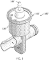
FIG. 5 is a front perspective view of another embodiment of a snap actuator and valve. -
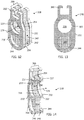
FIG. 6 is a longitudinal cross-section of another embodiment of a snap actuator and valve having a sprung gate member and a vent port in fluid communication with the pocket housing the sprung gate member. -
FIGS. 7-9 are a side perspective view, a bottom view, and a side perspective exploded view, respectively, of one embodiment of a sprung gate member. -
FIGS. 10-11 are a side perspective view and a side perspective exploded view, respectively, of another embodiment of a sprung gate member. -
FIGS. 12-14 are a side perspective view, a front view, and a longitudinal cross-section of yet another embodiment of a sprung gate member. -
FIG. 15 is an embodiment for a bellowed, endless elastic band. -
FIG. 16 is a longitudinal cross-sectional view of the bellowed, endless elastic band ofFIG. 15 . - The following detailed description will illustrate the general principles of the invention, examples of which are additionally illustrated in the accompanying drawings. In the drawings, like reference numbers indicate identical or functionally similar elements.
- As used herein "fluid" means any liquid, suspension, colloid, gas, plasma, or combinations thereof.
-
FIGS. 1-4 illustrate one embodiment of adevice 100 for use in an internal combustion engine, in particular as part of a brake vacuum boost system. Thedevice 100 includes ahousing 102 that may include acontainer portion 130 and acap 132 defining aninternal chamber 103 and having aport 108 in fluid communication with thechamber 103. As seen inFIGS. 1 and 2 , theport 108 enters thehousing 102 through thecontainer portion 130. However, in the alternate embodiment illustrated inFIG. 6 , the housing 102' again includes acontainer portion 130 and acap 132, but here the port 108' enters the housing 102' through thecap 132. Preferably, thecap 132 is sealingly connected to thecontainer portion 130. - Referring to
FIGS. 2-4 , housed within thechamber 103 is anactuator 104 that includes apiston 110 having astem 114 connectable to avalve mechanism 120. Thestem 114 has a proximal end 152 (which may be referred to herein as the coupling end) proximate to thevalve mechanism 120 and adistal end 154 removed from the valve mechanism 120 (labeled inFIG. 2 ). Thevalve mechanism 120, in this embodiment, includes aconduit 122 having a valve opening 124 and apocket 126 and includes agate member 128 at least partially receivable in thepocket 126 and having apassage 129 therethrough. As seen inFIG. 2 , thepocket 126 separates theconduit 122 into afirst section 123a and asecond section 123b. Other valves may be connected to theactuator 104 such as a poppet valve, a butterfly valve, or other known valves. - As seen in
FIG. 2 , theconduit 122 may be a tube that continuously, gradually tapers or narrows from both ends toward thevalve opening 124, thereby having its smallest inner diameter at thevalve opening 124. This hour glass-shaped cross-section 125, centered at thevalve opening 124, reduces the friction force acting on the surfaces of thegate member 128 during its opening. This gradual narrowing of theconduit 122 also minimizes the pressure drop across the valve. In another embodiment, as seen inFIG. 6 , theconduit 122 may have a uniforminner diameter 127 along its entire length. - In the embodiment of
FIGS. 1-4 , with thevalve mechanism 120 having agate member 128, thegate member 128 is connected to thepiston 110 by arail system 160 providing sliding movement of thegate member 128 along the longitudinal axis A (FIG. 2 ) of theconduit 122 thereby forming a seal within theconduit 122 in response to pressure within theconduit 122. The rail system 160 (best seen inFIGS. 3 and 4 ) includes aguide rail 162 near theproximal end 152 ofstem 114. Theguide rail 162 includesraceway grooves 164 on opposing sides thereof. Thegate member 128 includes aslider 166 shaped and configured to fit over theguide rail 162 and conform to theraceway grooves 164. - The
actuator 104 controls the opening and closing of thevalve mechanism 120, in particular thegate member 128, inFIGS. 2-4 , by the movement of thepiston 110. As seen inFIGS. 3 and 4 , thepiston 110 is movable between a starting position 140 (FIG. 3 ) and a secondary position 142 (FIG. 4 ). Thestarting position 140 in this embodiment (FIG. 3 ) is an open position of thevalve mechanism 120. In other embodiments, the starting position may be a closed position of the valve. Thepiston 110 at least partially includes a magnetically-attractable material 111 (or is made of such material) such that thepiston 110 is attractable to afirst magnet 116 and a second magnet 118 (seen in the cross-section ofFIG. 2 ). Aspring 112 is seated against thepiston 110 to bias thepiston 110 generally into thestarting position 140 and thefirst magnet 116 is positioned to assist thespring 112 in maintaining thepiston 110 in thestarting position 140. Thesecond magnet 118 is positioned to maintain thepiston 110 in the secondary position 142 (FIG. 4 ), when thepiston 110 moves to thesecondary position 142. - The
stem 114 of the piston may also extend therefrom opposite the valve mechanism, and, as seen inFIGS. 2-4 , be received in aguide channel 146 within thecap 132. Thecap 132 may also include aseat 148 for thespring 112. These features of thecap 132 provide alignment to the actuator and prevent twisting and/or buckling of the spring and piston. - The
actuator 104 may include afirst bumper 138 positioned to reduce noise between thepiston 110 and thehousing 102 when arriving in the startingposition 140 and asecond bumper 139 positioned to reduce noise between thepiston 110 and thehousing 102 when arriving in thesecondary position 142. Thefirst bumper 138 may also be positioned to seal theopening 150 between thehousing 102 and the valve mechanism 120 (seeFIGS. 2 and4 ). In one embodiment, opening 150 may be defined by a generally frustoconical surface. The first andsecond bumpers housing 102 or on a component of thepiston 110, such as thestem 114. - Still referring to
FIGS. 2-4 , thepiston 110 may also include a sealingmember 134 about its outer periphery as a lip seal against the interior surface ofchamber 103. The outer periphery of thepiston 110 may include anannular groove 136 in which to seat the sealingmember 134. In one embodiment, the sealingmember 134 may be an O-ring, a V-ring, or an X-ring. Alternately, the sealingmember 134 may be any other annular seal made of sealing material for sealing engagement against another member. - In operation, the
actuator 104 moves thepiston 110 by the introduction of fluid into or the removal of fluid from thechamber 103 via theport 108 and the assistance of themagnets piston 110 is seated in a starting position 140 (FIG. 3 ) and remains in this position held there by the spring force and the magnetic force of thefirst magnet 116, which may correspond to either an open or a closed position for an attached valve, until a threshold force is applied to thepiston 110 that overcomes the spring force and magnetic force of the first magnet. Once this threshold force is reached, thepiston 110 will move the full length of its travel to its secondary position 142 (FIG. 4 ) with the assistance of the magnetic force of the second magnet, which thereafter maintains thepiston 110 in thesecondary position 142. The movement of thepiston 110 through its full length of travel is a quick, nearly instantaneous movement substantially without pause therebetween, i.e., there is no lag or floating of the piston in between the startingposition 140 and thesecondary position 142, which may be described as a "snap" movement of the piston. This "snap," which without bumpers is an audible sound, is a result of the magnetic attraction of thesecond magnet 118 for thepiston 110, which acts to quickly move the piston to thesecondary position 142. Thesecond magnet 118 thereafter holds or maintains thepiston 110 in the secondary position until a lower threshold force is reached, at which point the piston moves back to itsstarting position 140 by again moving the full length of its travel as a snap-type movement. - The movement of the piston from its starting position to its secondary position may be described as a "snap" movement. This "snap" is a quick, nearly instantaneous movement of the piston the full length of its travel between the starting and secondary positions without a lag or floating of the piston therebetween. The "snap" action of the actuator as it travels between the starting position and the secondary position is facilitated by the presence of the magnets, which attract and pull the piston between the two positions. This is such a quick movement that without bumpers to reduce the noise, a snap-like sound can be heard as the piston contacts the housing as it arrives in the alternate position, which depending on the configuration of the actuator may be an "on" or an "off' position of the attached valve.
-
FIG. 6 illustrates another embodiment of a valve device, generally designated asreference 200, for use in an internal combustion engine. Thedevice 200 includes ahousing 102 that may include acontainer portion 130 and acap 132 defining aninternal chamber 103 and having aport 108 in fluid communication with thechamber 103. As seen inFIG. 6 , theport 108 enters thehousing 102 through thecontainer portion 130 and thecap portion 132, but is not limited thereto. As illustrated in alternate embodiments herein, theport 108 may enter through either thecontainer portion 130 or thecap portion 132 individually. Housed within thechamber 103 is an actuator 104 that includes apiston 110 having astem 114 connectable to avalve mechanism 120, aspring 112 for biasing thepiston 110 into a first position, and one ormore magnets 116 for magnetically attracting thepiston 110, as described above. - The
device 200 may include aposition sensor 92 to sense the position of thepiston 110 and allow for feedback to a controller (not shown) that controls the fluid flow throughport 108 intochamber 103. The position sensor may be as described inU.S. Provisional Application No. 61/662,255 - The
valve mechanism 120 inFIG. 6 includes aconduit 122 having avalve opening 124 and apocket 126 and includes a sprunggate 228 at least partially receivable in thepocket 126 and having apassage 229 passing through the sprunggate 228. The sprunggate 228 is moveable linearly withinpocket 126 in response to the linear movement of thepiston 110 to move the sprunggate 228 between an open position (seeFIG. 3 ) and a closed position (seeFIG. 4 ) within theconduit 122. Theconduit 122 is as described above. Thevalve opening 124 of the conduit may be a maximum of about 2 inches (50.8 mm) in diameter. In another embodiment, thevalve opening 124 is about 1 inch (25.4 mm) in diameter or less. In another embodiment, thevalve opening 124 is about 0.5 inch (12.7 mm) in diameter or less. In another embodiment, the valve opening is dimensioned to have a diameter between about 0.25 inch (6.35 mm) and about 0.5 inch (12.7 mm). - Referring to
FIGS. 7-9 , one embodiment of a sprung gate, generally designated asreference number 228, is illustrated. The sprunggate 228 includes afirst gate member 230, asecond gate member 232, and an endlesselastic band 234 received between the first andsecond gate members elastic band 234 may be described as being sandwiched between the first andsecond gate members FIG. 9 , thesecond gate member 232 includes atrack 236, for receiving a portion of the endless elastic band, as a portion of itsinterior surface 252. While not visible inFIGS. 7-9 , thefirst gate member 230 also includes atrack 236. In one embodiment, the elastic material is a natural or synthetic rubber. - The first and
second gate members FIGS. 7 and 9 the first andsecond gate members gate 228, as oriented relative to the page upon which the figures are printed. This allows similar performance of the valve regardless of the direction of fluid flow in theconduit 122. - Referring to
FIGS. 7 and 9 , the first and thesecond gate members opening 233 therein that defines a portion ofpassage 229. In an open position, such as illustrated inFIG. 6 , thepassage 229 through the sprunggate 228 is aligned with theconduit 122 to allow fluid to flow therethrough. The portion of thegate having passage 229 is referred to herein as the open position portion 240 (FIG. 7 ), and the adjacent portion, located opposite theslider 266, is referred to as theclosed position portion 242 because this portion of thegate 228, when moved to a closed position obstructs theconduit 122 to prevent fluid flow therethrough. Theclosed position portion 242 of eachgate member - Here, the endless
elastic band 234 is generally oval shaped and thereby includes aninner perimeter 282 defining an open space, anouter perimeter 284, and opposing first andsecond sides elastic band 234 is received in thetracks 236 of the first andsecond gate members first side 286 received in onetrack 236 and thesecond side 288 received in theother track 236. When theendless band 234 is seated in thetracks 236 of the first andsecond gate members second gate members FIG. 7 ). Thetracks 236 are positioned to inset the endless elastic band 234 a distance from the outer perimeter of the gate members as well. As seen inFIG. 8 , this construction defines achannel 254 around the outer surface of the endlesselastic band 234 between the first andsecond gate members gate 228 within thepocket 126 for fluid communication with avent port 170 shown inFIG. 6 . This venting viachannel 254 is generally perpendicular to the direction of fluid flow through theconduit 122 and vents fluid from thepocket 126 as the gate moves more fully into the pocket. - The endless
elastic band 234 is compressible between the first and thesecond gate members conduit 122. The endlesselastic band 234 biases the first and second gate members into a sealing engagement with opposing walls of thepocket 126. Additionally, the endlesselastic band 234 is expandable radially outward in response to forces applied to the endlesselastic band 234 by the fluid flowing through the conduit to form a seal between the endlesselastic band 234 and the outer wall portion of thetracks 236 in the first andsecond gate members - In operation, in the open position as illustrated in
FIG. 6 , the fluid flowing through the conduit, whether flowing left to right or right to left, passes throughpassage 229 in the sprunggate 228 and the pressure of the fluid provides a force acting on the endlesselastic band 234 directed radially outward thereby pressing the endless elastic band into sealing engagement with the outer perimeter of thetracks 236. This sealing engagement reduces or prevents fluid leakage into the actuator, which renders thegate 228 in the embodiment ofFIGS. 7-9 more leak resistant than the gate member illustrated inFIGS. 3 and 4 , which is a single-bodied, rigid gate. This embodiment is particularly suited for use with naturally aspirated engines, in particular with air flowing at atmospheric or sub-atmospheric pressures through theconduit 122. However, in an embodiment where theconduit 122 is connected to the boost pressure side of a supercharged air intake system, the leak protection provided by the endlesselastic band 234 aides in preventing the fluid flowing through theconduit 122 from generating pressures within thepocket 126 which could act to push the sprung gate 228 (and hence the piston 110) to another position or otherwise impede controlled movement thereof. The pressures in the supercharged engine, and experienced by the sprunggate 228 generally range between about 5 psi and about 30 psi. - The endless
elastic band 234 also produces a gate that is less sensitive to manufacturing tolerances, in particular with respect to the dimensions ofpocket 126 and the thickness of thegate members elastic band 234. Thepocket 126 is typically formed to have a width that is smaller than the unloaded width of the sprunggate 228 so as to produce an interference fit. In the sprunggate 228, the endlesselastic band 234 becomes compressed between the first andsecond gate members gate 228 is inserted into thepocket 126. The endless elastic band's biasing action on the first andsecond gate members pocket 126 biases or presses each respective gate member into a sealing engagement with a wall of the pocket to reduce or prevent leaks. Most importantly, the substantially lower modulus of elasticity of the endless elastic band versus that of therigid gate members gate 228 and resisting linear movement of the assembly along its path are substantially less. This reduces the frictional forces (Frictional force is equal to the normal force times the coefficient of friction) and thus the required solenoid operating force. This benefit is equally applicable to the other embodiments described below. - Referring now to
FIGS. 10 and 11 , a second embodiment of a sprung gate, generally designated as reference number 228', is provided, that similarly toFIGS. 7-9 , includes a first gate member 230', a second gate member 232', and an endlesselastic band 235 received between the first and second gate members 230', 232'. The endlesselastic band 235 may be described as being sandwiched between the first and second gate members 230', 232'. As seen inFIG. 9 , the second gate member 232' includes atrack 237 as a portion of its interior surface 252' for receiving a portion of the endlesselastic band 235. While not visible inFIGS. 10 and 11 , the first gate member 230' also includes atrack 237. Both gate members 230', 232' also include aslider 266' for slidingly connecting the gate 228' to acoupling end 152 of the piston 110 (FIG. 6 ) as described above. - Here, as illustrated in
FIG. 11 , the endlesselastic band 235 is generally a figure-eight shaped band of elastic material and thereby includes a firstinner perimeter 272 defining a first open space, a secondinner perimeter 273 defining a second open space, anouter perimeter 274, and opposing first andsecond sides elastic band 235 is received in thetracks 237 of the first and second gate members 230', 232' with thefirst side 276 received in onetrack 237 and thesecond side 278 received in theother track 237. Since the endlesselastic band 235 is figure-eight shaped, thetrack 237 is also typically figure-eight shaped. When theendless band 235 is seated in thetracks 237 of the first and second gate members 230', 232', the first and the second gate members 230', 232' are spaced apart from one another by a distance D' (FIG. 10 ). Thetracks 237 are positioned to recess the endless elastic band 235 a distance from the outer perimeter (i.e., inward a distance from the outer sides) of the first and second gate members 230', 232' to provide venting as described above with respect toFIGS. 6-9 . - The first and second gate members 230', 232' are structurally different from one another, but both have a
first opening 233' therein that defines a portion ofpassage 229 which, in an open position, is aligned with theconduit 122 to allow fluid to flow therethrough. This portion of the gate is referred to as the open position portion 240' (FIG. 10 ), and the adjacent portion thereto, opposite theslider 266', is referred to as the closed position portion 242' because this portion of the gate 228', when moved to a closed position, obstructs theconduit 122 to prevent fluid flow therethrough. In this embodiment, the closed position portion 242' of the first gate member 230' includes asecond opening 244 therethrough. The second opening may be dimensioned substantially the same as thefirst opening 233'. The second gate member 232' does not include a second opening in the closed position portion 242' thereof. Instead, the closed portion 242' of the second gate member 232' has a substantially continuous smooth exterior surface. The second gate member 232' may include a plug 253 projecting from its inner surface 252'. This plug 253 fits within the dimensions of the second open space defined by the endlesselastic band 235 and is dimensioned to be at least the size of thesecond opening 244 in the first gate member 230', which defines a smaller opening than the secondinner perimeter 273 of the endlesselastic band 235. The plug 253 may be a substantially smooth portion of the interior surface 252' of the second gate member 232'. - In the open position, fluid flowing through
passage 229 provides a force acting on the endlesselastic band 235 directed radially outward thereby pressing the endless elastic band into sealing engagement with the outer perimeter of thetracks 237. This sealing engagement reduces or prevents fluid leakage into the actuator andpocket 126, which renders the sprung gate 228' in the embodiment ofFIGS. 10 and 11 more leak resistant than the gate member illustrated inFIGS. 3 and 4 . - In the closed position, the fluid flow in the
conduit 122 may be in the direction toward the side of the sprung gate 228' defined by the first gate member 230'. In particular, this orientation of flow is beneficial when theconduit 122 is connected to the boost pressure side of a supercharged air intake system and is generally operated to stop boost pressure from flowing therethrough. This is so because the boost pressure passes through thesecond opening 244 and is directed by the plug 253 toward the secondinner perimeter 273 of the endlesselastic band 235 to act radially outwardly on the endless elastic band to sealingly engage it against thetracks 237 of the first and second gate members 230', 232'. The presence of thesecond opening 244 also minimizes the surface area of the exterior surface of the first gate member 230' upon which the boost pressure can apply a force acting parallel to the flow direction within theconduit 122 to axially compress the endlesselastic band 235. If the boost pressure does compress the endlesselastic band 235 in the axial direction, one of the gate members 230', 232' would move closer to the other, decreasing D', and creating a gap between one wall of thepocket 126 and that gate member through which fluid could leak. This is an undesirable result. Accordingly, for gate member 228', it would be undesirable for the boost pressure to flow into the conduit in a direction that would impact the second gate member's 232' substantially continuous smooth exterior surface. - Referring now to
FIGS. 12-14 , a universal sprung gate (operable with flow directed toward either of the first or the second gate members) is illustrated and designated byreference numeral 328. The universal sprunggate 328 has same first gate member 230' as the embodiment inFIGS. 10 and 11 , asecond gate member 332 that has the same general construction as the first gate member 230', aninner gate member 334 that provides the obstruction necessary for the closed position, a first endlesselastic band 346 disposed within a track defined between the first gate member 230' and theinner gate member 334, and a second endlesselastic band 348 disposed within a track defined between thesecond gate member 332 and theinner gate member 334. Thesecond gate member 332, seeFIG. 13 , includes afirst opening 333 in the open position portion 240', and asecond opening 344 in the closed position portion 242' thereof, and may include aslider 366. Theinner gate member 334 includes anopening 336 in an open position portion 240' thereof and has opposing substantially continuous exterior surfaces defining the closed position portion 242', which can obstruct the flow of fluid through the conduit when the universal sprunggate 328 is in the closed position. - In the embodiment of
FIGS. 12-14 , the figure-eight shaped endless elastic band is preferred because of the two openings in each of the first andsecond gate members 230', 332. The figure-eight shaped endlesselastic bands elastic band 346 is seated both in afirst track 352 in theinner gate member 334 and in atrack 237 in the first gate member 230', which are preferably in the shape of a figure-eight dimensioned to receive the first endlesselastic band 346. Similarly, the second endlesselastic band 348 is seated both in asecond track 354 in theinner gate member 334 and in atrack 337 in thesecond gate member 332, which are preferably in the shape of a figure-eight dimensioned to receive the second endlesselastic band 348. - In operation, the universal sprung
gate 328, in the open position and in the closed position, operates as described above with respect to the first gate member side of the sprung gate 228' ofFIGS. 10 and 11 . The universal sprunggate 328 may be used in normally aspirated, supercharged, or turbocharged engines without requiring any particular flow orientation. Its universal nature and the benefit of the reduced surface area in the closed position portion of each of the first and second gate members makes this gate function to seal the gate to reduce or prevent leakage into thepiston actuator pocket 126 regardless of the direction of flow through the conduit. This embodiment also has the benefit of providing amultiple channels 254 around the exterior of the endless elastic band to provide fluid communication between the actuator and the vent port 170 (FIG. 6 ) as described above. - In each embodiment of the sprung gates disclosed herein, the endless elastic band was illustrated as a generally smooth band having a generally rectangular cross-section as seen in
FIGS. 6 and14 . The endless elastic band, however, is not limited to such a construction. In another embodiment, the endless elastic band may have a generally irregular inner and outer surface as seen inFIGS. 15 and 16 . In this embodiment, the endless elastic band, is generally referred to as a bellowed, endlesselastic band 434, which has an undulatingouter perimeter 474 and aninner perimeter 476 oppositely undulating relative thereto. When the endlesselastic band 434 has the generally 8-shaped configuration, thecross member 435, forming the center of the eight, may also be bellowed. The bellows in thecross member 435 and the main part of the band, as shown inFIGS. 15 and 16 , are oriented transverse to the direction of fluid flow through the conduit and, hence, through the endless elastic band itself. The bellowed,elastic band 434 is advantageous because it provides more even compression of the band between the first and second gate members. - Having described the invention in detail and by reference to preferred embodiments thereof, it will be apparent that modifications and variations are possible without departing from the scope of the invention which is defined in the appended claims.
Claims (15)
- A valve having a sprung gate seated in a pocket within a conduit to control fluid flow through the conduit, the sprung gate comprising:a first endless elastic band having an inner perimeter defining an open space; anda first gate member and a second gate member each defining an opening therethrough in an open position portion thereof;wherein the first endless elastic band is sandwiched in compression between the first and second gate members with the open space thereof oriented for alignment with the opening in both of the first and second gate members, which are aligned to form a passage through the sprung gate, and applies a bias force to the first gate member and the second gate member biasing them away from one another;wherein the first endless elastic band is inset a distance from an outer perimeter of each of the first and second gate members and spaces the first and second gate members apart a distance to define a channel around the outer surface of the first endless elastic band for fluid flow around the sprung gate;wherein the first endless elastic band, the first gate member, and the second gate member are collectively movable linearly between an open position and a closed position within the pocket of the conduit.
- The valve of claim 1, wherein the first endless elastic band is generally oval-shaped or is generally 8-shaped.
- The valve of claim 1, wherein the first and second gate members each include an actuator connector portion.
- The valve of claim 1, wherein the first and second gate members each include a track positioned to inset the endless elastic band the distance from the outer perimeter of each of the first and second gate members.
- The valve of claim 1, wherein the first gate member defines a second opening therethrough in a closed position portion thereof and the second opening is aligned with a substantially continuous surface of the second gate member of the sprung gate.
- The valve of claim 5, wherein the substantially continuous surface of the second gate member is in a closed position portion thereof and is a plug projecting from its inner surface toward the second opening in the first gate member.
- The valve of claim 5, wherein the first endless elastic band is generally 8-shaped.
- The valve of claim 1, wherein the endless elastic band is a bellowed elastic band, wherein the bellows are oriented transverse to the direction of flow therethrough.
- A device comprising:the valve according to any of claims 1 to 8; andan actuator connected to the sprung gate;wherein the actuator moves the sprung gate between the open position and the closed position.
- The device of claim 9, wherein the actuator includes a rigid piston that is at least partially pneumatically activated.
- The device of claim 9, wherein the pocket includes a vent port.
- The device of claim 9, wherein the actuator includes a piston having a stem connected to the sprung gate and a spring for biasing the piston into a first position.
- The device of claim 12, wherein the actuator includes one or more magnets for magnetically attracting the piston, wherein a first magnet is positioned to assist the spring in maintaining the piston in a starting position.
- The device of claim 13, wherein a second magnet is positioned to maintain the piston in a secondary position.
- The device of claims 10, wherein the piston includes a sealing member about its outer periphery as a lip seal against an interior surface of a chamber defined by the actuator.
Priority Applications (1)
| Application Number | Priority Date | Filing Date | Title |
|---|---|---|---|
| EP21187224.7A EP3922888A1 (en) | 2013-05-31 | 2014-05-15 | Sprung gate valves movable by an actuator |
Applications Claiming Priority (3)
| Application Number | Priority Date | Filing Date | Title |
|---|---|---|---|
| US201361829463P | 2013-05-31 | 2013-05-31 | |
| PCT/US2014/038018 WO2014193653A2 (en) | 2013-05-31 | 2014-05-15 | Sprung gate valves movable by an actuator |
| EP14805033.9A EP3004697B1 (en) | 2013-05-31 | 2014-05-15 | Sprung gate valves movable by an actuator |
Related Parent Applications (1)
| Application Number | Title | Priority Date | Filing Date |
|---|---|---|---|
| EP14805033.9A Division EP3004697B1 (en) | 2013-05-31 | 2014-05-15 | Sprung gate valves movable by an actuator |
Related Child Applications (1)
| Application Number | Title | Priority Date | Filing Date |
|---|---|---|---|
| EP21187224.7A Division EP3922888A1 (en) | 2013-05-31 | 2014-05-15 | Sprung gate valves movable by an actuator |
Publications (2)
| Publication Number | Publication Date |
|---|---|
| EP3537014A1 true EP3537014A1 (en) | 2019-09-11 |
| EP3537014B1 EP3537014B1 (en) | 2021-08-04 |
Family
ID=51984057
Family Applications (3)
| Application Number | Title | Priority Date | Filing Date |
|---|---|---|---|
| EP14805033.9A Active EP3004697B1 (en) | 2013-05-31 | 2014-05-15 | Sprung gate valves movable by an actuator |
| EP21187224.7A Pending EP3922888A1 (en) | 2013-05-31 | 2014-05-15 | Sprung gate valves movable by an actuator |
| EP19169885.1A Active EP3537014B1 (en) | 2013-05-31 | 2014-05-15 | Sprung gate valves movable by an actuator |
Family Applications Before (2)
| Application Number | Title | Priority Date | Filing Date |
|---|---|---|---|
| EP14805033.9A Active EP3004697B1 (en) | 2013-05-31 | 2014-05-15 | Sprung gate valves movable by an actuator |
| EP21187224.7A Pending EP3922888A1 (en) | 2013-05-31 | 2014-05-15 | Sprung gate valves movable by an actuator |
Country Status (7)
| Country | Link |
|---|---|
| US (3) | US9845899B2 (en) |
| EP (3) | EP3004697B1 (en) |
| JP (1) | JP6466418B2 (en) |
| KR (1) | KR102085397B1 (en) |
| CN (1) | CN104295759B (en) |
| BR (1) | BR112015029774B1 (en) |
| WO (1) | WO2014193653A2 (en) |
Families Citing this family (15)
| Publication number | Priority date | Publication date | Assignee | Title |
|---|---|---|---|---|
| GB201213808D0 (en) * | 2012-08-03 | 2012-09-12 | Enston Robert P | Improved pipeline apparatus |
| EP3004697B1 (en) | 2013-05-31 | 2019-05-15 | Dayco IP Holdings, LLC | Sprung gate valves movable by an actuator |
| US9574677B2 (en) | 2013-05-31 | 2017-02-21 | Dayco Ip Holdings, Llc | Solenoid-powered gate valve |
| WO2015031770A1 (en) | 2013-08-30 | 2015-03-05 | Dayco Ip Holdings, Llc | Sprung gate valves movable by a solenoid actuator |
| US10221867B2 (en) | 2013-12-10 | 2019-03-05 | Dayco Ip Holdings, Llc | Flow control for aspirators producing vacuum using the venturi effect |
| US9666349B2 (en) * | 2013-12-11 | 2017-05-30 | Dayco Ip Holdings, Llc | Magnetically actuated shut-off valve |
| USD821302S1 (en) * | 2015-06-19 | 2018-06-26 | Dayco Ip Holdings, Llc | Venturi device |
| USD780296S1 (en) * | 2015-07-17 | 2017-02-28 | Dayco Ip Holdings, Llc | Actuated valve |
| US9599246B2 (en) | 2015-08-05 | 2017-03-21 | Dayco Ip Holdings, Llc | Magnetically actuated shut-off valve |
| US10712022B2 (en) * | 2015-10-20 | 2020-07-14 | A. O. Smith Corporation | Constant pressure switch apparatus and water heating system |
| US9599234B1 (en) * | 2015-12-07 | 2017-03-21 | Dayco Ip Holdings, Llc | Sprung gate valve |
| EP3516275B1 (en) | 2016-09-21 | 2021-06-23 | Dayco IP Holdings, LLC | Valve gate within a venturi gap of a venturi device for producing vacuum |
| US10473225B2 (en) | 2018-03-29 | 2019-11-12 | Hamilton Sundstrand Corporation | Passive valve |
| US11713816B1 (en) | 2019-08-22 | 2023-08-01 | Colt Irrigation, LLC | Pressure loss mitigation and durable valve |
| WO2022051768A1 (en) * | 2020-09-07 | 2022-03-10 | Dayco Ip Holdings, Llc | Magnetically latching valve for fuel vapor management systems and systems incorporating same |
Citations (7)
| Publication number | Priority date | Publication date | Assignee | Title |
|---|---|---|---|---|
| US2204142A (en) * | 1937-12-13 | 1940-06-11 | Macclatchie Mfg Company | Gate valve |
| US2306490A (en) * | 1939-09-11 | 1942-12-29 | Reed Roller Bit Co | Valve |
| US2705610A (en) * | 1951-05-05 | 1955-04-05 | Crane Co | Conduit valve |
| DE1751206A1 (en) * | 1968-04-20 | 1971-06-03 | Brown Boveri Krupp Reaktor | Device for fixing the reciprocating piston of a pneumatically or hydraulically operated reciprocating piston drive in its upper setting |
| JPS57167506A (en) * | 1981-04-06 | 1982-10-15 | Takeshi Kuroda | Hydraulic pressure cylinder |
| US5195722A (en) * | 1990-06-14 | 1993-03-23 | Bedner Michael P | Fool proof slide gate valve |
| EP0577933A1 (en) * | 1992-07-04 | 1994-01-12 | Thyssen Stahl Aktiengesellschaft | Gate valve for pipelines, particularly for furnace gas |
Family Cites Families (121)
| Publication number | Priority date | Publication date | Assignee | Title |
|---|---|---|---|---|
| US50746A (en) * | 1865-10-31 | Improvement in slide-valves | ||
| US82520A (en) * | 1868-09-29 | Improvement in steam slide-valves | ||
| DE501348C (en) | 1927-04-09 | 1930-07-01 | Wilh Strube G M B H | Gate valve |
| US2354967A (en) * | 1942-07-27 | 1944-08-01 | Macclatchie Mfg Company Of Cal | Line blind |
| US2472525A (en) * | 1945-06-27 | 1949-06-07 | Samuel H Edwards | Fluid pressure operated valve |
| US2552991A (en) * | 1948-04-16 | 1951-05-15 | South Hosuton Machine Company | Valve assembly |
| US2705019A (en) * | 1950-07-08 | 1955-03-29 | Alexander S Volpin | Gate valve |
| US2816730A (en) * | 1951-04-20 | 1957-12-17 | Rabas Eduard | Shut-off valve |
| US2913220A (en) * | 1955-06-20 | 1959-11-17 | Martin L Cover | Valve structure and method of installation |
| US2750962A (en) | 1955-06-28 | 1956-06-19 | Morton A Kreitchman | Solenoid operated valve structure |
| US2953346A (en) | 1956-02-29 | 1960-09-20 | Hochdruck Dichtungs Fabrik Sch | Gate valves |
| US2950897A (en) * | 1956-04-19 | 1960-08-30 | Walworth Co | Valve construction |
| US3069131A (en) | 1959-10-09 | 1962-12-18 | Marvin H Grove | Valve construction |
| US3113757A (en) | 1961-01-18 | 1963-12-10 | Nixon Phillip | Solenoid-operated gate valve |
| US3233862A (en) * | 1961-10-03 | 1966-02-08 | North American Aviation Inc | Fluid pressure balanced seal |
| US3203447A (en) | 1963-10-09 | 1965-08-31 | Skinner Prec Ind Inc | Magnetically operated valve |
| US3379214A (en) | 1965-01-15 | 1968-04-23 | Skinner Prec Ind Inc | Permanent magnet valve assembly |
| US3478771A (en) | 1967-09-15 | 1969-11-18 | Amca Pharm Lab Ltd | Sectional body gate valve with seat scraping means |
| FR1566417A (en) * | 1968-02-22 | 1969-05-09 | ||
| US3534307A (en) | 1969-02-13 | 1970-10-13 | Westinghouse Electric Corp | Electromagnetically or mechanically controlled magnetically-latched relay |
| US3575377A (en) * | 1969-02-20 | 1971-04-20 | Willamette Iron And Steel Co | Closure seal for gate valve and method |
| US3695578A (en) | 1969-05-20 | 1972-10-03 | Zimmermann & Jansen Gmbh Fa | Gate valve including fluid operated locking device |
| US3635601A (en) | 1970-08-10 | 1972-01-18 | Economics Lab | Fail-safe multiple product aspirator |
| US3768774A (en) | 1971-06-16 | 1973-10-30 | Vetco Offshore Ind Inc | Gate valve with pressure actuated plug seat |
| US3706321A (en) * | 1971-09-21 | 1972-12-19 | Acf Ind Inc | Manual override indicator for gate valve |
| GB1411303A (en) | 1973-05-02 | 1975-10-22 | Coplastix Ltd | Fluid flow control valves |
| US3871616A (en) * | 1973-12-10 | 1975-03-18 | Julian S Taylor | Gate valve disc |
| US4010928A (en) | 1974-12-27 | 1977-03-08 | Xomox Corporation | Piston-operated parallel-slide gate valve |
| US4056255A (en) | 1975-05-08 | 1977-11-01 | Lace Donald A | Valve actuator |
| CA1063454A (en) | 1975-10-29 | 1979-10-02 | Blakeway Industries Ltd. | Carburetor for an internal combustion engine |
| US4013090A (en) * | 1975-11-10 | 1977-03-22 | Taylor Julian S | Gate valve rotating disc |
| DE2714933C3 (en) | 1977-04-02 | 1981-02-26 | Guenter 5650 Solingen Burgmer | Flat slide |
| US4157169A (en) | 1977-10-12 | 1979-06-05 | Torr Vacuum Products | Fluid operated gate valve for use with vacuum equipment |
| US4146209A (en) * | 1977-12-08 | 1979-03-27 | Armco Steel Corporation | Gate valve |
| US4179099A (en) | 1978-07-03 | 1979-12-18 | Petroleum Designers, Inc. | Expanding gate valve |
| US4210308A (en) * | 1978-07-24 | 1980-07-01 | Sims James O | Valve |
| US4253487A (en) * | 1978-11-13 | 1981-03-03 | Exxon Research & Engineering Co. | Multi-position dual disc slide valve |
| US4385280A (en) | 1979-04-30 | 1983-05-24 | Minnesota Mining And Manufacturing Company | Low reluctance latching magnets |
| US4321652A (en) | 1979-04-30 | 1982-03-23 | Minnesota Mining And Manufacturing Co. | Low voltage transformer relay |
| JPS5690165A (en) * | 1979-12-20 | 1981-07-22 | Toshiba Corp | Gate valve for vacuum |
| US4340336A (en) | 1980-03-17 | 1982-07-20 | Hudson Oxygen Therapy Sales Company | Aspirator |
| US4341369A (en) | 1980-04-25 | 1982-07-27 | Acf Industries, Incorporated | Expanding gate valve assembly |
| DE3209199A1 (en) | 1981-07-03 | 1983-09-22 | Armaturenfabrik und Metallgießerei Koch und Müller GmbH, 4250 Bottrop | Gate valve for gas lines in particular |
| US4446887A (en) | 1981-12-21 | 1984-05-08 | Custom Oilfield Products, Inc. | Variable high pressure choke |
| JPS59214280A (en) | 1983-05-20 | 1984-12-04 | Hitachi Ltd | Cryostat |
| US4535967A (en) | 1984-01-05 | 1985-08-20 | Joy Manufacturing Company | Expanding gate valve with fluid-powered actuator |
| JPS61100423A (en) | 1984-10-23 | 1986-05-19 | Kureha Chem Ind Co Ltd | Apparatus for calendering thermoplastic resin |
| US4638193A (en) | 1984-11-23 | 1987-01-20 | Med-Tech Associates | Linear impulse motor |
| JPS61180423A (en) | 1985-02-06 | 1986-08-13 | Hitachi Ltd | Molecular beam epitaxy equipment |
| US4568058A (en) | 1985-07-01 | 1986-02-04 | Joy Manufacturing Company | Dual stage hydraulic actuator for expanding gate valve |
| US4585207A (en) | 1985-09-03 | 1986-04-29 | Joy Manufacturing Company | Expanding gate valve with pneumatic actuator |
| US4712585A (en) * | 1986-10-10 | 1987-12-15 | Red Man Pipe And Supply Company | Orifice plate holder |
| JPH041412Y2 (en) * | 1987-01-14 | 1992-01-17 | ||
| US4779582A (en) | 1987-08-12 | 1988-10-25 | General Motors Corporation | Bistable electromechanical valve actuator |
| US5000215A (en) | 1988-04-27 | 1991-03-19 | Phillips Edwin D | Bellows seal for valves and the like |
| JPH0364820A (en) | 1989-08-01 | 1991-03-20 | Mitsubishi Electric Corp | Electromagnetic switch device |
| US4934652A (en) | 1989-12-11 | 1990-06-19 | Otis Engineering Corporation | Dual stage valve actuator |
| DE3942542A1 (en) | 1989-12-22 | 1991-06-27 | Lungu Cornelius | BISTABLE MAGNETIC DRIVE WITH PERMANENT MAGNETIC HUBANKER |
| JPH082573Y2 (en) * | 1990-04-18 | 1996-01-29 | オーバル機器工業株式会社 | Outgoing reset mechanism |
| US5234088A (en) | 1990-09-19 | 1993-08-10 | Eaton Corporation | Phase change device with splitter spring |
| CN2085459U (en) | 1991-01-26 | 1991-09-25 | 刘廷元 | Ball expanding type plug for pipeline |
| US5172658A (en) | 1992-02-24 | 1992-12-22 | Eaton Corporation | Camshaft phase change device |
| US5235941A (en) | 1992-02-24 | 1993-08-17 | Eaton Corporation | Actuator for camshaft phase change device |
| US5627504A (en) | 1992-04-07 | 1997-05-06 | Avl Medical Instruments Ag | Electromagnetic actuating device, in particular for a valve |
| JPH0640530U (en) * | 1992-11-06 | 1994-05-31 | 石川島播磨重工業株式会社 | Vacuum gate valve |
| US5377955A (en) * | 1994-02-15 | 1995-01-03 | Baker; Dwight | Gate valve |
| DE4414176A1 (en) | 1994-04-22 | 1995-10-26 | Zimmermann & Jansen Gmbh | Knife gate valve |
| DE69501863T2 (en) | 1994-09-09 | 1998-07-23 | Gen Motors Corp | Actuator for an exhaust gas recirculation valve |
| CN1205065A (en) | 1995-10-16 | 1999-01-13 | 文卡特什·R·内夫里卡 | Valve |
| JP3665674B2 (en) | 1996-03-08 | 2005-06-29 | コスモ工機株式会社 | Flexible valve body in gate valve device |
| US5827331A (en) | 1996-05-24 | 1998-10-27 | W. R. Grace & Co.-Conn. | Electrode compositions |
| DE19727602C1 (en) | 1997-06-28 | 1998-10-15 | Voith Sulzer Stoffaufbereitung | Automatic liquid and solid material lock and release system |
| US5909525A (en) | 1997-08-06 | 1999-06-01 | Miller; Jack V. | Electro-optical relay |
| US6199587B1 (en) | 1998-07-21 | 2001-03-13 | Franco Shlomi | Solenoid valve with permanent magnet |
| DE19841499A1 (en) | 1998-09-10 | 2000-03-30 | Beru Ag | Spring-loaded actuation solenoid for e.g. vehicle valve, includes armature and core with varied angles of linear taper and thicknesses varying axially to produce maximum terminal closing- and pull-in forces |
| KR20000038207A (en) | 1998-12-04 | 2000-07-05 | Samsung Electronics Co Ltd | Structure having comb using electromagnetic force and actuator and inertia sensing sensor using the same |
| KR100324894B1 (en) | 1999-04-19 | 2002-02-28 | 김덕용 | Switch using uni-solenoid |
| CA2270785C (en) | 1999-05-04 | 2005-08-16 | Chih-Sheng Sheng | Magnet device with double fixing positions for changing the magnetic circuit |
| GB9920166D0 (en) | 1999-08-25 | 1999-10-27 | Alpha Thames Limited | Valve actuator |
| US6158718A (en) | 1999-09-17 | 2000-12-12 | Erc Industries, Inc. | Gate valve |
| DE19953788A1 (en) | 1999-11-09 | 2001-05-10 | Bosch Gmbh Robert | Electromagnetic actuator |
| US6425410B1 (en) | 2000-09-06 | 2002-07-30 | Julian S. Taylor | High impact type gate pressure release valve |
| JP3425937B2 (en) | 2000-12-04 | 2003-07-14 | 入江工研株式会社 | Gate valve |
| US6442955B1 (en) | 2001-03-06 | 2002-09-03 | Stuart Peter Oakner | Condensate overflow safety switch |
| CN2480633Y (en) | 2001-06-01 | 2002-03-06 | 彭国军 | Wedge type double gate board gate valve |
| EP1333207B1 (en) | 2002-02-01 | 2005-08-03 | Vetco Gray Controls Limited | Linear actuators |
| CN2534389Y (en) | 2002-03-14 | 2003-02-05 | 胡军 | Ultramicro hydraulic electronic pump |
| DE10242816B4 (en) | 2002-09-14 | 2014-02-27 | Andreas Stihl Ag & Co | Electromagnetic valve |
| EP1669567B1 (en) | 2003-09-19 | 2012-03-21 | Nissan Diesel Motor Co., Ltd. | Exhaust gas purification device of engine |
| US7017886B1 (en) | 2004-03-17 | 2006-03-28 | Romanus Aniekezie Ngene-Igwe | Sliding gate valve |
| US20060016477A1 (en) | 2004-07-23 | 2006-01-26 | Algis Zaparackas | Vacuum enhancing check valve |
| US7108008B2 (en) | 2004-08-23 | 2006-09-19 | Ranco Incorporated Of Delaware | Reversing valve assembly with improved pilot valve mounting structure |
| US7240693B2 (en) | 2005-03-30 | 2007-07-10 | Robertshaw Controls Company | Pressure regulated solenoid valve having integral mounting structure |
| US7523916B2 (en) | 2006-10-05 | 2009-04-28 | Vetco Gray Inc. | Fail-safe gate valve |
| US7819378B2 (en) | 2006-10-30 | 2010-10-26 | Vetco Gray Inc. | Floating plug gate valve |
| JP4977900B2 (en) | 2007-07-20 | 2012-07-18 | Smc株式会社 | Linear operated gate valve |
| DE102007037333A1 (en) | 2007-08-08 | 2009-02-26 | Daimler Ag | actuator |
| EP2195567A1 (en) | 2007-10-02 | 2010-06-16 | Aktiebolaget SKF | A valve actuator |
| US7748217B2 (en) | 2007-10-04 | 2010-07-06 | Delphi Technologies, Inc. | System and method for modeling of turbo-charged engines and indirect measurement of turbine and waste-gate flow and turbine efficiency |
| EP2443327B1 (en) | 2009-06-18 | 2016-08-31 | Cummins IP, Inc. | Apparatus and method for reductant line heating control |
| US8434511B2 (en) | 2009-07-08 | 2013-05-07 | Gt Advanced Cz Llc | Retractable and expandable water cooled valve gate useful for sealing a hot processing chamber |
| CN101963240A (en) | 2009-07-22 | 2011-02-02 | 戴学祥 | Expanding type metal seated ball valve |
| US8925520B2 (en) | 2010-03-10 | 2015-01-06 | Ford Global Technologies, Llc | Intake system including vacuum aspirator |
| CN201679974U (en) | 2010-04-30 | 2010-12-22 | 什邡慧丰采油机械有限责任公司 | Expanding high temperature flat valve |
| JP5573351B2 (en) | 2010-05-17 | 2014-08-20 | いすゞ自動車株式会社 | SCR system |
| CN201866285U (en) | 2010-09-02 | 2011-06-15 | 浙江工贸职业技术学院 | Expanded heat-dissipation double-seal double-plate gate valve |
| PE20141077A1 (en) | 2011-01-28 | 2014-09-05 | Weir Minerals India Private Ltd | A SEALING ELEMENT FOR A GATE VALVE |
| US8662473B2 (en) | 2011-04-05 | 2014-03-04 | Vetco Gray Inc. | Replaceable floating gate valve seat seal |
| US9222583B2 (en) | 2011-04-08 | 2015-12-29 | Cameron International Corporation | Split gate valve |
| SG185830A1 (en) | 2011-05-09 | 2012-12-28 | Cameron Int Corp | Split gate valve with biasing mechanism |
| US8777184B2 (en) * | 2011-06-13 | 2014-07-15 | Tom J. Brock | Gate valve |
| JP5270734B2 (en) | 2011-09-09 | 2013-08-21 | 株式会社ティクスIks | Expanded gate valve reverse seat structure |
| WO2013049643A1 (en) | 2011-09-30 | 2013-04-04 | Integrated Equipment, Inc. | Expanding gate valve assembly |
| US9027536B2 (en) | 2012-06-26 | 2015-05-12 | Ford Global Technologies, Llc | Crankcase ventilation and vacuum generation |
| US9068657B2 (en) * | 2012-10-19 | 2015-06-30 | Varian Semiconductor Equipment Associates, Inc. | Gate valve with improved seal arrangement |
| US9574677B2 (en) | 2013-05-31 | 2017-02-21 | Dayco Ip Holdings, Llc | Solenoid-powered gate valve |
| EP3004697B1 (en) | 2013-05-31 | 2019-05-15 | Dayco IP Holdings, LLC | Sprung gate valves movable by an actuator |
| WO2015031770A1 (en) | 2013-08-30 | 2015-03-05 | Dayco Ip Holdings, Llc | Sprung gate valves movable by a solenoid actuator |
| US10221867B2 (en) | 2013-12-10 | 2019-03-05 | Dayco Ip Holdings, Llc | Flow control for aspirators producing vacuum using the venturi effect |
| KR102238212B1 (en) | 2014-06-09 | 2021-04-08 | 데이코 아이피 홀딩스 엘엘시 | Venturi devices with dual venturi flow paths |
| US9828953B2 (en) | 2014-12-01 | 2017-11-28 | Dayco Ip Holdings, Llc | Evacuator system having multi-port evacuator |
-
2014
- 2014-05-15 EP EP14805033.9A patent/EP3004697B1/en active Active
- 2014-05-15 BR BR112015029774-9A patent/BR112015029774B1/en active IP Right Grant
- 2014-05-15 EP EP21187224.7A patent/EP3922888A1/en active Pending
- 2014-05-15 EP EP19169885.1A patent/EP3537014B1/en active Active
- 2014-05-15 JP JP2016516684A patent/JP6466418B2/en active Active
- 2014-05-15 KR KR1020157034403A patent/KR102085397B1/en active IP Right Grant
- 2014-05-15 WO PCT/US2014/038018 patent/WO2014193653A2/en active Application Filing
- 2014-05-15 US US14/277,815 patent/US9845899B2/en active Active
- 2014-05-30 CN CN201410391935.7A patent/CN104295759B/en active Active
-
2017
- 2017-11-22 US US15/820,840 patent/US10323767B2/en active Active
-
2019
- 2019-05-06 US US16/404,049 patent/US11067177B2/en active Active
Patent Citations (7)
| Publication number | Priority date | Publication date | Assignee | Title |
|---|---|---|---|---|
| US2204142A (en) * | 1937-12-13 | 1940-06-11 | Macclatchie Mfg Company | Gate valve |
| US2306490A (en) * | 1939-09-11 | 1942-12-29 | Reed Roller Bit Co | Valve |
| US2705610A (en) * | 1951-05-05 | 1955-04-05 | Crane Co | Conduit valve |
| DE1751206A1 (en) * | 1968-04-20 | 1971-06-03 | Brown Boveri Krupp Reaktor | Device for fixing the reciprocating piston of a pneumatically or hydraulically operated reciprocating piston drive in its upper setting |
| JPS57167506A (en) * | 1981-04-06 | 1982-10-15 | Takeshi Kuroda | Hydraulic pressure cylinder |
| US5195722A (en) * | 1990-06-14 | 1993-03-23 | Bedner Michael P | Fool proof slide gate valve |
| EP0577933A1 (en) * | 1992-07-04 | 1994-01-12 | Thyssen Stahl Aktiengesellschaft | Gate valve for pipelines, particularly for furnace gas |
Also Published As
| Publication number | Publication date |
|---|---|
| US20190257441A1 (en) | 2019-08-22 |
| US20140353534A1 (en) | 2014-12-04 |
| EP3922888A1 (en) | 2021-12-15 |
| US10323767B2 (en) | 2019-06-18 |
| US20180094744A1 (en) | 2018-04-05 |
| EP3537014B1 (en) | 2021-08-04 |
| EP3004697A4 (en) | 2017-01-18 |
| WO2014193653A3 (en) | 2015-01-22 |
| KR102085397B1 (en) | 2020-04-14 |
| EP3004697A2 (en) | 2016-04-13 |
| US11067177B2 (en) | 2021-07-20 |
| CN104295759B (en) | 2017-08-11 |
| CN104295759A (en) | 2015-01-21 |
| JP6466418B2 (en) | 2019-02-06 |
| BR112015029774B1 (en) | 2022-05-17 |
| WO2014193653A2 (en) | 2014-12-04 |
| JP2016526135A (en) | 2016-09-01 |
| KR20160013055A (en) | 2016-02-03 |
| US9845899B2 (en) | 2017-12-19 |
| EP3004697B1 (en) | 2019-05-15 |
| BR112015029774A2 (en) | 2017-07-25 |
Similar Documents
| Publication | Publication Date | Title |
|---|---|---|
| US11067177B2 (en) | Sprung gate valves movable by an actuator | |
| US9574677B2 (en) | Solenoid-powered gate valve | |
| EP3039319B1 (en) | Sprung gate valves movable by a solenoid actuator | |
| EP3387299B1 (en) | Sprung gate valve | |
| EP3094897B1 (en) | Solenoid-powered gate valve | |
| KR20160083907A (en) | Diesel engine fluid coolant system having a solenoid-powered gate valve | |
| CN112135992B (en) | Two position gate valve and spring gate valve with full flow open position and restricted flow open position | |
| GB2476075A (en) | Solenoid operated valve |
Legal Events
| Date | Code | Title | Description |
|---|---|---|---|
| PUAI | Public reference made under article 153(3) epc to a published international application that has entered the european phase |
Free format text: ORIGINAL CODE: 0009012 |
|
| STAA | Information on the status of an ep patent application or granted ep patent |
Free format text: STATUS: THE APPLICATION HAS BEEN PUBLISHED |
|
| AC | Divisional application: reference to earlier application |
Ref document number: 3004697 Country of ref document: EP Kind code of ref document: P |
|
| AK | Designated contracting states |
Kind code of ref document: A1 Designated state(s): AL AT BE BG CH CY CZ DE DK EE ES FI FR GB GR HR HU IE IS IT LI LT LU LV MC MK MT NL NO PL PT RO RS SE SI SK SM TR |
|
| STAA | Information on the status of an ep patent application or granted ep patent |
Free format text: STATUS: REQUEST FOR EXAMINATION WAS MADE |
|
| STAA | Information on the status of an ep patent application or granted ep patent |
Free format text: STATUS: EXAMINATION IS IN PROGRESS |
|
| 17P | Request for examination filed |
Effective date: 20200310 |
|
| RBV | Designated contracting states (corrected) |
Designated state(s): AL AT BE BG CH CY CZ DE DK EE ES FI FR GB GR HR HU IE IS IT LI LT LU LV MC MK MT NL NO PL PT RO RS SE SI SK SM TR |
|
| 17Q | First examination report despatched |
Effective date: 20200417 |
|
| STAA | Information on the status of an ep patent application or granted ep patent |
Free format text: STATUS: EXAMINATION IS IN PROGRESS |
|
| GRAP | Despatch of communication of intention to grant a patent |
Free format text: ORIGINAL CODE: EPIDOSNIGR1 |
|
| STAA | Information on the status of an ep patent application or granted ep patent |
Free format text: STATUS: GRANT OF PATENT IS INTENDED |
|
| INTG | Intention to grant announced |
Effective date: 20210302 |
|
| GRAS | Grant fee paid |
Free format text: ORIGINAL CODE: EPIDOSNIGR3 |
|
| GRAA | (expected) grant |
Free format text: ORIGINAL CODE: 0009210 |
|
| STAA | Information on the status of an ep patent application or granted ep patent |
Free format text: STATUS: THE PATENT HAS BEEN GRANTED |
|
| AC | Divisional application: reference to earlier application |
Ref document number: 3004697 Country of ref document: EP Kind code of ref document: P |
|
| AK | Designated contracting states |
Kind code of ref document: B1 Designated state(s): AL AT BE BG CH CY CZ DE DK EE ES FI FR GB GR HR HU IE IS IT LI LT LU LV MC MK MT NL NO PL PT RO RS SE SI SK SM TR |
|
| REG | Reference to a national code |
Ref country code: GB Ref legal event code: FG4D |
|
| REG | Reference to a national code |
Ref country code: AT Ref legal event code: REF Ref document number: 1417302 Country of ref document: AT Kind code of ref document: T Effective date: 20210815 |
|
| REG | Reference to a national code |
Ref country code: CH Ref legal event code: EP |
|
| REG | Reference to a national code |
Ref country code: DE Ref legal event code: R096 Ref document number: 602014079313 Country of ref document: DE |
|
| REG | Reference to a national code |
Ref country code: IE Ref legal event code: FG4D |
|
| REG | Reference to a national code |
Ref country code: LT Ref legal event code: MG9D |
|
| REG | Reference to a national code |
Ref country code: NL Ref legal event code: MP Effective date: 20210804 |
|
| REG | Reference to a national code |
Ref country code: AT Ref legal event code: MK05 Ref document number: 1417302 Country of ref document: AT Kind code of ref document: T Effective date: 20210804 |
|
| PG25 | Lapsed in a contracting state [announced via postgrant information from national office to epo] |
Ref country code: ES Free format text: LAPSE BECAUSE OF FAILURE TO SUBMIT A TRANSLATION OF THE DESCRIPTION OR TO PAY THE FEE WITHIN THE PRESCRIBED TIME-LIMIT Effective date: 20210804 Ref country code: FI Free format text: LAPSE BECAUSE OF FAILURE TO SUBMIT A TRANSLATION OF THE DESCRIPTION OR TO PAY THE FEE WITHIN THE PRESCRIBED TIME-LIMIT Effective date: 20210804 Ref country code: RS Free format text: LAPSE BECAUSE OF FAILURE TO SUBMIT A TRANSLATION OF THE DESCRIPTION OR TO PAY THE FEE WITHIN THE PRESCRIBED TIME-LIMIT Effective date: 20210804 Ref country code: SE Free format text: LAPSE BECAUSE OF FAILURE TO SUBMIT A TRANSLATION OF THE DESCRIPTION OR TO PAY THE FEE WITHIN THE PRESCRIBED TIME-LIMIT Effective date: 20210804 Ref country code: PT Free format text: LAPSE BECAUSE OF FAILURE TO SUBMIT A TRANSLATION OF THE DESCRIPTION OR TO PAY THE FEE WITHIN THE PRESCRIBED TIME-LIMIT Effective date: 20211206 Ref country code: NO Free format text: LAPSE BECAUSE OF FAILURE TO SUBMIT A TRANSLATION OF THE DESCRIPTION OR TO PAY THE FEE WITHIN THE PRESCRIBED TIME-LIMIT Effective date: 20211104 Ref country code: HR Free format text: LAPSE BECAUSE OF FAILURE TO SUBMIT A TRANSLATION OF THE DESCRIPTION OR TO PAY THE FEE WITHIN THE PRESCRIBED TIME-LIMIT Effective date: 20210804 Ref country code: AT Free format text: LAPSE BECAUSE OF FAILURE TO SUBMIT A TRANSLATION OF THE DESCRIPTION OR TO PAY THE FEE WITHIN THE PRESCRIBED TIME-LIMIT Effective date: 20210804 Ref country code: BG Free format text: LAPSE BECAUSE OF FAILURE TO SUBMIT A TRANSLATION OF THE DESCRIPTION OR TO PAY THE FEE WITHIN THE PRESCRIBED TIME-LIMIT Effective date: 20211104 Ref country code: LT Free format text: LAPSE BECAUSE OF FAILURE TO SUBMIT A TRANSLATION OF THE DESCRIPTION OR TO PAY THE FEE WITHIN THE PRESCRIBED TIME-LIMIT Effective date: 20210804 |
|
| PG25 | Lapsed in a contracting state [announced via postgrant information from national office to epo] |
Ref country code: PL Free format text: LAPSE BECAUSE OF FAILURE TO SUBMIT A TRANSLATION OF THE DESCRIPTION OR TO PAY THE FEE WITHIN THE PRESCRIBED TIME-LIMIT Effective date: 20210804 Ref country code: LV Free format text: LAPSE BECAUSE OF FAILURE TO SUBMIT A TRANSLATION OF THE DESCRIPTION OR TO PAY THE FEE WITHIN THE PRESCRIBED TIME-LIMIT Effective date: 20210804 Ref country code: GR Free format text: LAPSE BECAUSE OF FAILURE TO SUBMIT A TRANSLATION OF THE DESCRIPTION OR TO PAY THE FEE WITHIN THE PRESCRIBED TIME-LIMIT Effective date: 20211105 |
|
| PG25 | Lapsed in a contracting state [announced via postgrant information from national office to epo] |
Ref country code: NL Free format text: LAPSE BECAUSE OF FAILURE TO SUBMIT A TRANSLATION OF THE DESCRIPTION OR TO PAY THE FEE WITHIN THE PRESCRIBED TIME-LIMIT Effective date: 20210804 |
|
| PG25 | Lapsed in a contracting state [announced via postgrant information from national office to epo] |
Ref country code: DK Free format text: LAPSE BECAUSE OF FAILURE TO SUBMIT A TRANSLATION OF THE DESCRIPTION OR TO PAY THE FEE WITHIN THE PRESCRIBED TIME-LIMIT Effective date: 20210804 |
|
| REG | Reference to a national code |
Ref country code: DE Ref legal event code: R097 Ref document number: 602014079313 Country of ref document: DE |
|
| PG25 | Lapsed in a contracting state [announced via postgrant information from national office to epo] |
Ref country code: SM Free format text: LAPSE BECAUSE OF FAILURE TO SUBMIT A TRANSLATION OF THE DESCRIPTION OR TO PAY THE FEE WITHIN THE PRESCRIBED TIME-LIMIT Effective date: 20210804 Ref country code: SK Free format text: LAPSE BECAUSE OF FAILURE TO SUBMIT A TRANSLATION OF THE DESCRIPTION OR TO PAY THE FEE WITHIN THE PRESCRIBED TIME-LIMIT Effective date: 20210804 Ref country code: RO Free format text: LAPSE BECAUSE OF FAILURE TO SUBMIT A TRANSLATION OF THE DESCRIPTION OR TO PAY THE FEE WITHIN THE PRESCRIBED TIME-LIMIT Effective date: 20210804 Ref country code: EE Free format text: LAPSE BECAUSE OF FAILURE TO SUBMIT A TRANSLATION OF THE DESCRIPTION OR TO PAY THE FEE WITHIN THE PRESCRIBED TIME-LIMIT Effective date: 20210804 Ref country code: CZ Free format text: LAPSE BECAUSE OF FAILURE TO SUBMIT A TRANSLATION OF THE DESCRIPTION OR TO PAY THE FEE WITHIN THE PRESCRIBED TIME-LIMIT Effective date: 20210804 Ref country code: AL Free format text: LAPSE BECAUSE OF FAILURE TO SUBMIT A TRANSLATION OF THE DESCRIPTION OR TO PAY THE FEE WITHIN THE PRESCRIBED TIME-LIMIT Effective date: 20210804 |
|
| PLBE | No opposition filed within time limit |
Free format text: ORIGINAL CODE: 0009261 |
|
| STAA | Information on the status of an ep patent application or granted ep patent |
Free format text: STATUS: NO OPPOSITION FILED WITHIN TIME LIMIT |
|
| 26N | No opposition filed |
Effective date: 20220506 |
|
| PG25 | Lapsed in a contracting state [announced via postgrant information from national office to epo] |
Ref country code: IT Free format text: LAPSE BECAUSE OF FAILURE TO SUBMIT A TRANSLATION OF THE DESCRIPTION OR TO PAY THE FEE WITHIN THE PRESCRIBED TIME-LIMIT Effective date: 20210804 |
|
| PG25 | Lapsed in a contracting state [announced via postgrant information from national office to epo] |
Ref country code: SI Free format text: LAPSE BECAUSE OF FAILURE TO SUBMIT A TRANSLATION OF THE DESCRIPTION OR TO PAY THE FEE WITHIN THE PRESCRIBED TIME-LIMIT Effective date: 20210804 |
|
| REG | Reference to a national code |
Ref country code: CH Ref legal event code: PL |
|
| REG | Reference to a national code |
Ref country code: BE Ref legal event code: MM Effective date: 20220531 |
|
| GBPC | Gb: european patent ceased through non-payment of renewal fee |
Effective date: 20220515 |
|
| PG25 | Lapsed in a contracting state [announced via postgrant information from national office to epo] |
Ref country code: MC Free format text: LAPSE BECAUSE OF FAILURE TO SUBMIT A TRANSLATION OF THE DESCRIPTION OR TO PAY THE FEE WITHIN THE PRESCRIBED TIME-LIMIT Effective date: 20210804 Ref country code: LU Free format text: LAPSE BECAUSE OF NON-PAYMENT OF DUE FEES Effective date: 20220515 Ref country code: LI Free format text: LAPSE BECAUSE OF NON-PAYMENT OF DUE FEES Effective date: 20220531 Ref country code: CH Free format text: LAPSE BECAUSE OF NON-PAYMENT OF DUE FEES Effective date: 20220531 |
|
| PG25 | Lapsed in a contracting state [announced via postgrant information from national office to epo] |
Ref country code: IE Free format text: LAPSE BECAUSE OF NON-PAYMENT OF DUE FEES Effective date: 20220515 Ref country code: FR Free format text: LAPSE BECAUSE OF NON-PAYMENT OF DUE FEES Effective date: 20220531 |
|
| PG25 | Lapsed in a contracting state [announced via postgrant information from national office to epo] |
Ref country code: GB Free format text: LAPSE BECAUSE OF NON-PAYMENT OF DUE FEES Effective date: 20220515 Ref country code: BE Free format text: LAPSE BECAUSE OF NON-PAYMENT OF DUE FEES Effective date: 20220531 |
|
| P01 | Opt-out of the competence of the unified patent court (upc) registered |
Effective date: 20230522 |
|
| PGFP | Annual fee paid to national office [announced via postgrant information from national office to epo] |
Ref country code: DE Payment date: 20230503 Year of fee payment: 10 |
|
| PG25 | Lapsed in a contracting state [announced via postgrant information from national office to epo] |
Ref country code: HU Free format text: LAPSE BECAUSE OF FAILURE TO SUBMIT A TRANSLATION OF THE DESCRIPTION OR TO PAY THE FEE WITHIN THE PRESCRIBED TIME-LIMIT; INVALID AB INITIO Effective date: 20140515 |