EP3516275B1 - Valve gate within a venturi gap of a venturi device for producing vacuum - Google Patents
Valve gate within a venturi gap of a venturi device for producing vacuum Download PDFInfo
- Publication number
- EP3516275B1 EP3516275B1 EP17853857.5A EP17853857A EP3516275B1 EP 3516275 B1 EP3516275 B1 EP 3516275B1 EP 17853857 A EP17853857 A EP 17853857A EP 3516275 B1 EP3516275 B1 EP 3516275B1
- Authority
- EP
- European Patent Office
- Prior art keywords
- motive
- venturi
- discharge
- gate valve
- venturi device
- Prior art date
- Legal status (The legal status is an assumption and is not a legal conclusion. Google has not performed a legal analysis and makes no representation as to the accuracy of the status listed.)
- Active
Links
- 239000012530 fluid Substances 0.000 claims description 39
- 238000004891 communication Methods 0.000 claims description 14
- 239000011800 void material Substances 0.000 claims description 13
- 230000007704 transition Effects 0.000 claims description 5
- 238000013519 translation Methods 0.000 claims description 2
- 238000002485 combustion reaction Methods 0.000 claims 4
- 238000007789 sealing Methods 0.000 description 11
- 230000003068 static effect Effects 0.000 description 7
- 230000008901 benefit Effects 0.000 description 6
- 230000000694 effects Effects 0.000 description 4
- 238000010276 construction Methods 0.000 description 3
- 238000007796 conventional method Methods 0.000 description 2
- 230000003247 decreasing effect Effects 0.000 description 2
- 230000003467 diminishing effect Effects 0.000 description 2
- 230000009977 dual effect Effects 0.000 description 2
- 239000000446 fuel Substances 0.000 description 2
- 239000011521 glass Substances 0.000 description 2
- 238000010438 heat treatment Methods 0.000 description 2
- 239000002184 metal Substances 0.000 description 2
- 230000009467 reduction Effects 0.000 description 2
- 239000000243 solution Substances 0.000 description 2
- 238000003466 welding Methods 0.000 description 2
- 230000008859 change Effects 0.000 description 1
- 239000000084 colloidal system Substances 0.000 description 1
- 238000013461 design Methods 0.000 description 1
- 239000007789 gas Substances 0.000 description 1
- 230000006872 improvement Effects 0.000 description 1
- 238000001746 injection moulding Methods 0.000 description 1
- 239000007788 liquid Substances 0.000 description 1
- 238000004519 manufacturing process Methods 0.000 description 1
- 238000010926 purge Methods 0.000 description 1
- 230000035484 reaction time Effects 0.000 description 1
- 230000001105 regulatory effect Effects 0.000 description 1
- 239000000725 suspension Substances 0.000 description 1
- 230000002195 synergetic effect Effects 0.000 description 1
- 238000012360 testing method Methods 0.000 description 1
- 238000011144 upstream manufacturing Methods 0.000 description 1
- 238000009423 ventilation Methods 0.000 description 1
Images


Classifications
-
- F—MECHANICAL ENGINEERING; LIGHTING; HEATING; WEAPONS; BLASTING
- F02—COMBUSTION ENGINES; HOT-GAS OR COMBUSTION-PRODUCT ENGINE PLANTS
- F02M—SUPPLYING COMBUSTION ENGINES IN GENERAL WITH COMBUSTIBLE MIXTURES OR CONSTITUENTS THEREOF
- F02M35/00—Combustion-air cleaners, air intakes, intake silencers, or induction systems specially adapted for, or arranged on, internal-combustion engines
- F02M35/10—Air intakes; Induction systems
- F02M35/10209—Fluid connections to the air intake system; their arrangement of pipes, valves or the like
- F02M35/10229—Fluid connections to the air intake system; their arrangement of pipes, valves or the like the intake system acting as a vacuum or overpressure source for auxiliary devices, e.g. brake systems; Vacuum chambers
-
- B—PERFORMING OPERATIONS; TRANSPORTING
- B60—VEHICLES IN GENERAL
- B60T—VEHICLE BRAKE CONTROL SYSTEMS OR PARTS THEREOF; BRAKE CONTROL SYSTEMS OR PARTS THEREOF, IN GENERAL; ARRANGEMENT OF BRAKING ELEMENTS ON VEHICLES IN GENERAL; PORTABLE DEVICES FOR PREVENTING UNWANTED MOVEMENT OF VEHICLES; VEHICLE MODIFICATIONS TO FACILITATE COOLING OF BRAKES
- B60T13/00—Transmitting braking action from initiating means to ultimate brake actuator with power assistance or drive; Brake systems incorporating such transmitting means, e.g. air-pressure brake systems
- B60T13/10—Transmitting braking action from initiating means to ultimate brake actuator with power assistance or drive; Brake systems incorporating such transmitting means, e.g. air-pressure brake systems with fluid assistance, drive, or release
- B60T13/66—Electrical control in fluid-pressure brake systems
- B60T13/72—Electrical control in fluid-pressure brake systems in vacuum systems or vacuum booster units
-
- F—MECHANICAL ENGINEERING; LIGHTING; HEATING; WEAPONS; BLASTING
- F16—ENGINEERING ELEMENTS AND UNITS; GENERAL MEASURES FOR PRODUCING AND MAINTAINING EFFECTIVE FUNCTIONING OF MACHINES OR INSTALLATIONS; THERMAL INSULATION IN GENERAL
- F16K—VALVES; TAPS; COCKS; ACTUATING-FLOATS; DEVICES FOR VENTING OR AERATING
- F16K27/00—Construction of housing; Use of materials therefor
- F16K27/04—Construction of housing; Use of materials therefor of sliding valves
- F16K27/044—Construction of housing; Use of materials therefor of sliding valves slide valves with flat obturating members
- F16K27/047—Construction of housing; Use of materials therefor of sliding valves slide valves with flat obturating members with wedge-shaped obturating members
-
- F—MECHANICAL ENGINEERING; LIGHTING; HEATING; WEAPONS; BLASTING
- F16—ENGINEERING ELEMENTS AND UNITS; GENERAL MEASURES FOR PRODUCING AND MAINTAINING EFFECTIVE FUNCTIONING OF MACHINES OR INSTALLATIONS; THERMAL INSULATION IN GENERAL
- F16K—VALVES; TAPS; COCKS; ACTUATING-FLOATS; DEVICES FOR VENTING OR AERATING
- F16K3/00—Gate valves or sliding valves, i.e. cut-off apparatus with closing members having a sliding movement along the seat for opening and closing
- F16K3/02—Gate valves or sliding valves, i.e. cut-off apparatus with closing members having a sliding movement along the seat for opening and closing with flat sealing faces; Packings therefor
- F16K3/0281—Guillotine or blade-type valves, e.g. no passage through the valve member
-
- F—MECHANICAL ENGINEERING; LIGHTING; HEATING; WEAPONS; BLASTING
- F16—ENGINEERING ELEMENTS AND UNITS; GENERAL MEASURES FOR PRODUCING AND MAINTAINING EFFECTIVE FUNCTIONING OF MACHINES OR INSTALLATIONS; THERMAL INSULATION IN GENERAL
- F16K—VALVES; TAPS; COCKS; ACTUATING-FLOATS; DEVICES FOR VENTING OR AERATING
- F16K3/00—Gate valves or sliding valves, i.e. cut-off apparatus with closing members having a sliding movement along the seat for opening and closing
- F16K3/02—Gate valves or sliding valves, i.e. cut-off apparatus with closing members having a sliding movement along the seat for opening and closing with flat sealing faces; Packings therefor
- F16K3/16—Gate valves or sliding valves, i.e. cut-off apparatus with closing members having a sliding movement along the seat for opening and closing with flat sealing faces; Packings therefor with special arrangements for separating the sealing faces or for pressing them together
-
- B—PERFORMING OPERATIONS; TRANSPORTING
- B60—VEHICLES IN GENERAL
- B60T—VEHICLE BRAKE CONTROL SYSTEMS OR PARTS THEREOF; BRAKE CONTROL SYSTEMS OR PARTS THEREOF, IN GENERAL; ARRANGEMENT OF BRAKING ELEMENTS ON VEHICLES IN GENERAL; PORTABLE DEVICES FOR PREVENTING UNWANTED MOVEMENT OF VEHICLES; VEHICLE MODIFICATIONS TO FACILITATE COOLING OF BRAKES
- B60T13/00—Transmitting braking action from initiating means to ultimate brake actuator with power assistance or drive; Brake systems incorporating such transmitting means, e.g. air-pressure brake systems
- B60T13/10—Transmitting braking action from initiating means to ultimate brake actuator with power assistance or drive; Brake systems incorporating such transmitting means, e.g. air-pressure brake systems with fluid assistance, drive, or release
- B60T13/24—Transmitting braking action from initiating means to ultimate brake actuator with power assistance or drive; Brake systems incorporating such transmitting means, e.g. air-pressure brake systems with fluid assistance, drive, or release the fluid being gaseous
- B60T13/46—Vacuum systems
-
- F—MECHANICAL ENGINEERING; LIGHTING; HEATING; WEAPONS; BLASTING
- F16—ENGINEERING ELEMENTS AND UNITS; GENERAL MEASURES FOR PRODUCING AND MAINTAINING EFFECTIVE FUNCTIONING OF MACHINES OR INSTALLATIONS; THERMAL INSULATION IN GENERAL
- F16K—VALVES; TAPS; COCKS; ACTUATING-FLOATS; DEVICES FOR VENTING OR AERATING
- F16K27/00—Construction of housing; Use of materials therefor
- F16K27/04—Construction of housing; Use of materials therefor of sliding valves
- F16K27/044—Construction of housing; Use of materials therefor of sliding valves slide valves with flat obturating members
-
- F—MECHANICAL ENGINEERING; LIGHTING; HEATING; WEAPONS; BLASTING
- F16—ENGINEERING ELEMENTS AND UNITS; GENERAL MEASURES FOR PRODUCING AND MAINTAINING EFFECTIVE FUNCTIONING OF MACHINES OR INSTALLATIONS; THERMAL INSULATION IN GENERAL
- F16K—VALVES; TAPS; COCKS; ACTUATING-FLOATS; DEVICES FOR VENTING OR AERATING
- F16K3/00—Gate valves or sliding valves, i.e. cut-off apparatus with closing members having a sliding movement along the seat for opening and closing
- F16K3/28—Gate valves or sliding valves, i.e. cut-off apparatus with closing members having a sliding movement along the seat for opening and closing with resilient valve members
-
- F—MECHANICAL ENGINEERING; LIGHTING; HEATING; WEAPONS; BLASTING
- F16—ENGINEERING ELEMENTS AND UNITS; GENERAL MEASURES FOR PRODUCING AND MAINTAINING EFFECTIVE FUNCTIONING OF MACHINES OR INSTALLATIONS; THERMAL INSULATION IN GENERAL
- F16K—VALVES; TAPS; COCKS; ACTUATING-FLOATS; DEVICES FOR VENTING OR AERATING
- F16K3/00—Gate valves or sliding valves, i.e. cut-off apparatus with closing members having a sliding movement along the seat for opening and closing
- F16K3/30—Details
- F16K3/314—Forms or constructions of slides; Attachment of the slide to the spindle
Definitions
- This application relates to Venturi devices for producing vacuum using the Venturi effect, more particularly to such devices having a valve gate within the Venturi gap to control flow through the Venturi gap.
- Engines for example vehicle engines, are being downsized and boosted, which is reducing the available vacuum from the engine. This vacuum has many potential uses, including use by the vehicle brake booster.
- Vacuum pumps have a significant cost and weight penalty to the engine, their electric power consumption can require additional alternator capacity, and their inefficiency can hinder fuel economy improvement actions.
- Venturi device that generates vacuum by creating an engine air flow path through the Venturi device to generate a suction vacuum.
- the flow through (i.e., into the motive section of) existing Venturi devices is typically controlled by a valve in series therewith, which entails connections, tubing, assembly steps, etc.
- Venturi device and a system comprising such device as defined in the appended set of claims.
- the Venturi devices disclosed allow to generate increased vacuum pressure and increased suction mass flow rates while decreasing the consumption of engine air.
- fluid means any liquid, suspension, colloid, gas, plasma, or combinations thereof.
- FIGS. 1 and 2 illustrate different views of an Venturi device 100.
- the Venturi device 100 may be used in an engine, for example, in a vehicle's engine to provide vacuum to a device.
- the Venturi device 100 is connected to a device requiring vacuum 102, and the Venturi device 100 creates vacuum for said device 102 by the flow of air through a passageway 104, extending generally the length of the Venturi device, designed to create the Venturi effect.
- Venturi device 100 includes a body 106 defining passageway 104 and having three or more ports that are connectable to an engine or components connected thereto.
- the ports include: (1) a motive port 108, which may be connected to a source of clean air, e.g., from the engine intake air cleaner, that is positioned upstream of a throttle; (2) a suction port 110, which can connect via an optional check valve 111 to the device requiring vacuum 102; (3) an outlet 112, which is connected to an engine intake manifold downstream of the throttle of the engine; and, optionally, (4) a bypass port 114.
- Each of the respective ports 108, 110, 112, and 114 may include a connector feature 117 on the outer surface thereof for connecting the respective port to a hose or other component in the engine.
- Check valve 111 is preferably arranged to prevent fluid from flowing from the suction port 110 to the application device 102.
- the device requiring vacuum 102 is a vehicle brake boost device, positive crankcase ventilation (PCV) device, or fuel purge device.
- the device requiring vacuum 102 is a hydraulic valve.
- the bypass port 114 may be connected to the device requiring vacuum 102 and, optionally, may include a check valve 120 in the fluid flow path 122 therebetween.
- Check valve 120 is preferably arranged to control the flow of fluid to or from the bypass port 114 to the application device 102.
- the Venturi device 100 is generally a "T-shaped" Venturi device defining an inner passageway along a central longitudinal axis B bisected by the suction port 110.
- the inner passageway 104 includes a first tapering portion 128 (also referred to herein as the motive cone) in the motive section 116 of the body 106 coupled to a second tapering portion 129 (also referred to herein as the discharge cone) in the discharge section 146 of the body 106.
- first tapering portion 128 and the second tapering portion 129 are aligned end to end having the motive outlet end 132 facing the discharge inlet end 134 and defining a Venturi gap 152 therebetween, which defines a fluid junction placing the suction port 110 in fluid communication with both the motive section 116 and the discharge section 146 of the inner passageway 104.
- the Venturi gap 152 as used herein means the lineal distance between the motive outlet end 132 and the discharge inlet end 134.
- the vehicle manufacturer When an Venturi device, such as Venturi device 100, is for use in a vehicle engine, the vehicle manufacturer typically selects the size of both the motive port 108 and outlet 112 based on the tubing/hose size available for connection of the Venturi device to the engine or components thereof. Additionally, the vehicle manufacturer typically selects the maximum motive flow rate available for use in the Venturi device, which in turn will dictate the area of the interior opening defined at the motive outlet end 132, i.e., the motive outlet 133. Accordingly, the vehicle manufacturer's selected parameters for the particular engine dictate the ratio of the motive outlet 133 to the outlet 112.
- the disclosed Venturi devices 100 significantly reduce the compromise between the desire to produce high suction flow rates at low (5 kPa to 30 kPa) source/discharge pressures and increased depth of vacuum at higher (30 kPa to 60 kPa) source discharge pressures.
- This reduction in the compromise is accomplished by changing the configuration for the motive outlet 133 and the discharge inlet 135 (defined by the discharge inlet end 134) to increase the perimeter of the inner passageway 104 at the motive outlet end 132 and the discharge inlet end 134, such as presented in FIGS. 5 and 6 .
- FIGS. 5A-5B and 6 at least the interior surface of the motive outlet end 132 (the motive outlet 133) and the interior surface of the discharge inlet end 134 (the discharge inlet 135) are ellipse-shaped, but may alternately have a polygonal form.
- the interior of the inner passageway 104 extending away from the motive outlet end 132 and away from the discharge inlet end 134, in opposite directions, from the Venturi gap 152, may be constructed to have the same general shape.
- FIG. 7 illustrates one embodiment of the shape of the internal passageway within the motive section of the Venturi device, but equally, if rotated 180 degrees illustrates the internal passageway within the discharge section.
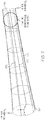
- the circular opening at the motive inlet end 130 is connected to the ellipse-shaped motive outlet 133 by hyperbola lines 170 that provide the advantage of flow lines at the motive outlet end 132 being parallel to one another.
- the motive inlet end 130 and the discharge outlet end 136 may also define ellipse-shaped or some other polygonal form openings at some point prior thereto and transition from said shapes to a circular cross-section to form a hose connecting portion, for example similar to hose-connecting portion 119, having connector features 117 on the exterior thereof.
- the suction port 110 has a central longitudinal axis C generally perpendicular to the body's central longitudinal axis B.
- the optional bypass port 114 may likewise have a central longitudinal axis D that is generally perpendicular to the body's central longitudinal axis B.
- the bypass port 114 may intersect the second tapering section 129 adjacent to, but downstream of the discharge outlet end 136.
- the body 106 may thereafter, i.e., downstream of this intersection of the bypass port, continue with a cylindrically uniform inner diameter until it terminates at the outlet 112.
- the bypass port 114 and/or the suction port 110 may be canted relative to axis B and/or to one another.
- the suction port 110 and the bypass port 114 are aligned with one another and have the same orientation relative to the body's central longitudinal axis B.
- the suction port 110 and the bypass port 114 may be offset from one another and can be positioned relative to components within the engine that they will connect to for ease of connection.
- the suction port 110 includes a suction inlet 138 and a suction outlet 135, which is the discharge inlet 134, and similarly to the first tapering section 128, may gradually, continuously taper as a cone along its length from the larger dimensioned suction inlet 138 to a smaller dimensioned suction outlet 135 or it can be a generally cylindrical tube.
- the bypass port 114 when present, may also gradually, continuously taper as a cone along its length, in particular from a smaller dimensioned end 162 to a larger dimensioned end 160, or it can be a generally cylindrical tube. Depending upon the attachment of the Venturi device into a system, the bypass port 114 may operate with the larger dimensioned end 160 as the inlet and the smaller dimensioned end 162 as the outlet or vice versa.
- the suction port 110 includes an enlarged region defining a void 150 in fluid communication with Venturi gap 152 or conversely the Venturi gap 152 may be considered part of void 150.
- the fluid junction of the suction port 110 with inner passageway 104 is generally centered relative to the Venturi gap 152 and the void 150 is generally aligned with the suction port's central longitudinal axis C and transitions the first tapering portion 128 into the second tapering portion 129.
- the void 150 may be shaped as parallelepiped whose length is similar to the suction port's interior cross-section dimension(s), but whose bottom is an arcuate projection projecting downward away from the suction port 110.
- the void In a cross-section taken transverse to the body's central longitudinal axis B along the suction port's central longitudinal axis C, the void is seen to be generally U-shaped around and/or over the discharge inlet end 134 and the motive outlet end 132 as best understood by viewing FIGS. 2 , 4A , and 5A in combination.
- the suction port extends downward around the sides of the motive outlet end 132 and the sides of the discharge inlet end 134 and defines the void 150 between all sides thereof.
- the exterior profile of the motive outlet end 132 and the discharge inlet end 134 both generally match their respective internal shapes.
- Venturi device 100 the flow of motive air through the first tapering portion 128 increases its speed, which creates low static pressure in the void 150. This low static pressure draws air from the suction port 110 into the Venturi gap 152 and into the discharge section 146 through the discharge inlet (suction outlet) 135.
- the Venturi device 100 may be operated to meet the following geometric ratios: Representative Symbol Ratio A' suction inlet area / suction outlet area B' motive inlet area / motive outlet area C' discharge outlet area / discharge inlet area
- the ratio A' should be between 3 and 12, and the ratio B' should be greater than 4, and the ratio C' should be greater than 4.
- the ratio A' should be between 3 and 12, and the ratio B' should be greater than 4, and the ratio C' should be greater than 4.
- the outlet end of the motive cone and the inlet end of the discharge cone each have circular internal cross-sections and circular exterior profiles and thereby define a Venturi gap that is a frustum having a circular outer periphery. From this drawing, one of the limitations to suction flow is illustrated - the area at the fluid junction of the suction port to the motive cone and the discharge cone.
- the area of the Venturi gap is increased by increasing the perimeter of the outlet end 132 and the inlet end 134 without increasing the overall inner dimension of the first tapering section 128 and the second tapering section 129 (preferably with no increase in the mass flow rate).
- motive outlet end 132 and discharge inlet end 134 are changed from being circular to being non-circular as described above.
- shapes that are not circular, each with a perimeter and a cross sectional area. These include polygons, or straight-line segments connected to each other, non-circular curves, and even fractal curves. To minimize cost a curve is simpler and easy to manufacture and inspect, and has a desirable perimeter length.
- FIGS. 4A-AB and 5A-5B illustrate embodiments with improved fluid junctions where the suction port 110 meets the motive outlet end 132 and the discharge inlet end 134.
- the smallest area of the flow path from the suction port 110 to the Venturi gap 152 is the frustum defined between the motive outlet end 132 and the discharge inlet end 134, see FIGS. 4B and 5B .
- the outlet end 132 of the motive cone 128 and the inlet end 134 of the discharge cone 129 each have inner and outer elliptical perimeters and thereby define a Venturi gap 152 that is a frustum having an elliptical outer periphery.
- FIGS. 4A-AB and 5A-5B illustrate embodiments with improved fluid junctions where the suction port 110 meets the motive outlet end 132 and the discharge inlet end 134.
- the smallest area of the flow path from the suction port 110 to the Venturi gap 152 is the frustum defined between the motive outlet end 132 and the discharge in
- the outlet end 132 of the motive cone 128 and the inlet end 134 of the discharge cone 129 each have inner and outer generally rectangular-shaped perimeters (with rounded corners) and thereby define a Venturi gap 152 that is a frustum having a generally rectangular-shaped outer periphery. While the embodiments in the figures have the same perimeter for the outlet end 132 and the inlet end 134, i.e., both are elliptical or both are generally rectangular, the outlet end 132 and the inlet end 134 may have differently shaped perimeters, i.e., one may be elliptical while the other is generally rectangular. Additionally, the motive outlet end 132 and the discharge inlet end 134 may terminate with a rounded chamfer to improve the directionality of the flow of the fluid from the suction port 110 in to the discharge inlet end 134.
- the outlet end 132 of the motive cone 128 for each embodiment is dimensionally smaller than the inlet end 134 of the discharge cone 129. This difference in dimension is identified as offset 140.
- the offset is seen in that the length of the major axis Y of the motive outlet end 132 is less than the length of the major axis Y' of the discharge inlet end 134 and may also have a length of the minor axis X of the motive outlet end 132 that is less than the length of the minor axis X' of the discharge inlet end 134.
- the elliptical- or polygonal-shaped internal cross-section of the motive outlet end of the converging motive section has a ratio of the major axis to the minor axis of about 2 to about 4, and the elliptical- or polygonal-shaped internal cross-section of the inlet end of the diverging discharge section is offset, relative to the elliptical- or polygonal-shaped internal cross-section of the outlet end of the converging motive section, by the ratio of the difference of the discharge inlet area and the motive outlet area to the peak motive flow rate, which is then multiplied by a constant k 1 to have a unitless ratio of greater than 0.28.
- Offset ratio discharge inlet area ⁇ motive outlet area / peak motive flow rate * k 1
- k 1 c at the motive outlet end * D fluid at the motive outlet end
- c is the speed of sound
- D fluid is the density of the fluid (typically air).
- the Venturi gap between the motive outlet end and the discharge inlet end has a gap ratio defined as the area of the Venturi gap divided by the motive flow times a constant k 2 (to have a unitless ratio).
- the gap ratio is greater than 4.7.
- the elliptical- or polygonal-shaped internal cross-section of the motive outlet end 132 has an eccentricity of between 0 to, and including 1. In another embodiment, the elliptical- or polygonal-shaped internal cross-section of the outlet end has an eccentricity of between about 0.4 to, and including about 0.97.
- the outlet end 132 and the inlet end 134 are elliptical in profile thereby having a major axis (Y) and a minor axis (X).
- the perimeter of an ellipse is not given by a simple exact equation.
- the area is of 3.14 mm 2 with a perimeter of 6.28 mm.
- the ratio of perimeter to area is mathematically equal to 2 for a circular internal cross-section for the motive outlet end and the discharge inlet end.
- the perimeter can be increased while holding the cross-sectional area fixed.
- This increase in perimeter provides the advantage of increasing the intersection area at the junction between the suction port, the motive cone, and the discharge cone, resulting in an increase in the suction port flow rate.
- the motive outlet end 132 and the discharge inlet end 134 are generally rectangular in profile thereby having a length and a width and hence two axes, a major axis U and a minor axis V.
- the Venturi device's generally rectangular profile for the outlet end 132 and inlet end 134 include semicircular ends corresponding to the width of the rectangular portion.
- the orientation of the profile of the outlet and inlet ends 132, 134 should not be construed to be limited thereto.
- the area of this rectangle is equal to the sum of the areas of the two end semicircles plus the area of the straight section in between the semicircles.
- the perimeter of the rectangle is the lengths of the two sides plus the lengths of the semicircular ends.
- Another way to increase suction flow would be to lengthen the distance between the outlet end 132 of the motive cone 128 and the inlet end 134 of the discharge cone 129. As the motive flow travels through the Venturi gap it mixes with suction air. This combined flow has the effect of increasing the static pressure towards the discharge end of the Venturi. Lengthening this distance offers diminishing returns, and because the motive flow is largely unconstrained in the Venturi, offers the risk of turbulence and flow disturbance, which would reduce the velocity and increase static pressure. Accordingly, the increase in perimeter described above is preferred over lengthening the distance, but the two could be combined to avoid the diminishing returns.
- the Venturi devices disclosed herein may be molded as a monolithic body. In one embodiment, the Venturi devices are formed by injection molding.
- the Venturi gap 152 is a lineal distance proportional to the (motive mass flow rate) n , wherein n is 0.25 to 0.8, and the offset between the motive outlet and the discharge inlet is also proportional to the (motive mass flow rate) n , where n is 0.25 to 0.8, and the elliptical- or polygonal-shaped internal cross-section of the outlet end has an eccentricity of between 0 to, and including 1, or more preferably between about 0.4 to, and including about 0.97.
- n for the Venturi gap and n for the offset may both be 0.4 to 0.6.
- n for the Venturi gap and n for the offset are both 0.5 and the eccentricity is between about 0.4 to, and including 0.97.
- the gap ratio is set at a value equal to the ellipse minor diameter when the ellipse major diameter divided by three is equal to the ellipse minor diameter, wherein each value is accurate to +/-10%.
- engine air i.e. filtered air
- Air exiting the Venturi device at the discharge port can be connected to the engine air at a point where the pressure is lower than that of the motive port.
- the motion of the air from the motive to discharge port draws the air down the motive cone, which can be a straight cone or a hyperbolic profile as described above.
- the reduction in area causes the velocity of the air to increase. Because this is an enclosed space the laws of fluid mechanics state that the static pressure must decrease when the fluid velocity increases.
- the minimum cross-sectional area of the motive cone abuts the Venturi gap.
- the discharge cone which is either a straight cone or a hyperbolic profile.
- the discharge region can continue as a straight or hyperbolic profile cone until it joins the discharge port, or it can transition to a simple cylindrical or tapered passage.
- the minimum cross-sectional area end of the discharge cone is larger than that of the minimum cross section area end of the motive cone. The larger area is to provide area for the flow of air from the suction port. This change in area down the discharge cone slows the air velocity down again, with a subsequent increase in its static pressure.
- the Venturi gap connects to the suction port, which exposes air in the suction port/passage to the same low static pressure that exists in the air passing at high velocity between the motive and discharge cones.
- the pressure created here can be lower than the pressure at the discharge port, which is known already to be lower than that at the motive port.
- This low pressure may be used for a variety of applications on a vehicle, such as for evacuating a vehicle brake boost canister, as is known to those skilled in the art.
- the pressure at the discharge port is low enough to quickly lower the pressure at the application device. Since the area of the connection between the discharge cone or passage and the bypass passage is quite large relative to the connection between the suction passage and the Venturi gap, this optional connection can assist in evacuation of the application device initially.
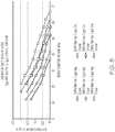
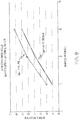
- a 3 gps Venturi device having an elliptical motive outlet and an elliptical discharge inlet at the Venturi gap and a hyperboloid internal profile in the motive and discharge sections (referred to as the "hyperboloid ellipse Venturi device") as illustrated in FIG. 7 was operated under conditions of 10 kPa manifold vacuum, 15 kPa manifold vacuum, and 20 kPa manifold vacuum with increasing brake boost canister vacuum and compared to a 3 gps conical circular Venturi device under the same conditions.
- a conical circular Venturi device is one that has a circular motive outlet and a circular discharge inlet and a conical internal profile in the motive and discharge sections.
- the hyperboloid ellipse Venturi device provided a synergistic effect of the hyperboloid internal profile with the ellipse-shaped openings that exceeded the results of the conical circular Venturi device.
- the hyperboloid ellipse Venturi device provided higher suction flow rates over an increasing range of brake boost canister vacuum from 12 kPa to about 67 kPa.
- the hyperboloid ellipse Venturi device performed generally similar to the conical circular Venturi device when it was at 20 kPa manifold pressure, evidencing unexpected, superior performance.
- FIGS. 9 and 10 the same Venturi devices compared for FIG. 8 were compared with respect to the ultimate vacuum the Venturi device could generate and the time needed for the Venturi device to evacuate a canister to create vacuum.
- the outlet 112 was in fluid communication with an intake manifold of the engine, the suction port was in fluid communication with a vehicle brake boost canister, and the motive inlet was connected to a source of clean air. As shown in the graph of FIG.
- the hyperboloid ellipse Venturi device disclosed herein provides a deeper vacuum compared to the conical circular Venturi device under the same operating conditions, i.e., at 10, 15, and 20 kPa of manifold vacuum the hyperboloid ellipse Venturi device had an ultimate vacuum that was greater by at least 5 kPa.
- the hyperboloid ellipse Venturi device was superior in evacuating a brake boost canister compared to the conical circular Venturi device. At a manifold vacuum pressure of 10 kPa, the hyperboloid ellipse Venturi device was over just under 4.5 seconds faster at evacuating the canister.
- the hyperboloid ellipse Venturi device was about 2 seconds faster. Faster evacuation times at lower manifold vacuum provides for faster reaction time and improved performance. But, as seen in these graphs, not only does the Venturi device with the hyperboloid elliptical profile have faster evacuation time, it also provides a deeper vacuum at manifold vacuums of 10, 15, and 20 kPa. This dual benefit was a surprising, unexpected result from changing the shapes of the motive outlet and the discharge inlet that defines the Venturi gap and using an internal passageway that changes/taper according to a hyperbolic function.
- any of the various embodiments of the Venturi device for generating vacuum described herein may include a valve gate 300 within the Venturi gap 252 to control the passage of fluid from the motive section 216 to the discharge section 246.
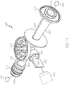
- the Venturi device 200 has a body, such as lower body 206 in FIG. 11 , defining a Venturi gap between an outlet end 232 of the converging motive section 216 and an inlet end 234 of a diverging discharge section 246, and a suction port 210 in fluid communication with the Venturi gap 252, a gate valve 300 linearly translatable to open and close the Venturi gap 252, and an actuator 310 connected to the gate valve 300 to operatively move the gate valve 300 between an open position O ( FIG.
- the converging motive section 216 defines a circular-shaped motive inlet 208 and defines an elliptical- or polygonal-shaped motive outlet 233, and the diverging discharge section 246 defines an elliptical- or polygonal-shaped discharge inlet 235.
- Each of the respective ports 208 and 212 may include a connector feature 217 on the outer surface thereof for connecting the respective port to a hose or other component in the engine.
- the other ports 210 and 282 may each include a lip or other types of connector for sealing connecting to other components with fluid tight seals, for example, an upper housing 204 to suction port 210 and an actuator 310 to the port 282.
- the upper housing 204 and the lower housing 206 at the junction of the suction port 210, may form a check valve 211 having a sealing disc 213 seated therein.
- the fingers 218 extending upward away from the suction port 210 of the lower body 206 define a seat for the sealing disc 213 for an open position of the check valve 211.
- the upper housing 204 defines a passageway 220 leading to an entrance 222, which may comprise a plurality of openings, to a chamber 224 of the check valve 211 and, hence, to the suction chamber 250 of the lower body 206.
- the lower body 206 defines a gate pocket 280 that transects a central longitudinal axis A of the converging motive section 216.
- the gate pocket 280 terminates at the exterior of the lower body 206 with a connector 281 connectable to an actuator 310.
- the gate pocket 280 has a trapezoid-shape, viewed in cross-section parallel to the central longitudinal axis A, that is wider at an end more proximate the suction port 210 than at its opposite end.
- the gate valve 300 is slidingly seated within the gate pocket 280.
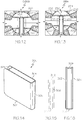
- the gate valve 300 is made of a thin piece of non-corroding metal or plastic folded, bent, or molded into a generally U-shaped continuous piece, viewed in longitudinal cross-section ( FIG. 16 ), shaped to close off the motive exit 233 and the discharge inlet 235 when in the closed position C of FIG. 12 .
- the continuous, opposing sides 302, 304 are spaced apart a distance apart to define void 308 therebetween that is in fluid communication with the suction port 210 at all times.
- a first side 302 of the gate valve 300 is in sealing engagement with the outlet end 233 of the converging motive section 216 and the second side 304 is in sealing engagement with the inlet end 235 of the diverging section 246.
- the opposing sides 302, 304 of the gate valve 300 each act as a leaf spring, biased generally away from one another to form the sealing engagements.
- the size i.e., the distance from the surface 302 to the surface 304, as measured at either the top or bottom 314 or the top 312, is such that the surfaces touch the outlet end 233 of the motive and the inlet end 235 of the discharge. This provides two benefits to this invention.
- the drag created by the interference will ensure that the valve 300 will remain fixed in position when in either the closed position C or the open position O. This will eliminate any wear that would occur if the valve 300 was free to rattle about.
- the difference in pressure between the motive port and the discharge port biases the gate always in the same direction, toward the discharge passage. By ensuring that the valve 300 is biased against toward the discharge passage, potential leakage between the motive port and the discharge port is minimized.
- the gate valve 300 has a trapezoid-shaped back 306 that is wider at an end 312 more proximate the suction port 210 than the opposite end 314.
- the actuator 310 is a pneumatic actuator connected to the gate valve to operatively move the gate valve between the open position O and the closed position C.
- the pneumatic actuator may be operated using the very vacuum created by the Venturi device for a self-regulated system configuration.
- Example pneumatic actuators are discussed in co-pending U.S. applications Serial No. 14/154,268 and Serial No. 14/277,815 .
- the actuator 310 is an electromagnetic actuator connected to the gate valve 300 to operatively move the gate valve between an open position and a closed position, for example, a solenoid.
- An example solenoid is discussed in co-pending U.S. application Serial No. 14/473,151 .
- the gate valve 300 is positioned relative to the elliptical- or polygonal-shaped motive outlet 233 for linear translation at the shortest stroke distance, which is in a plane parallel to a minor axis of the motive outlet 233.
- a circular discharge inlet having a 4 mm radius has a stroke distance of 4 mm, but an ellipse-shaped discharge inlet having the same area as the 4 mm circle having a minor axis of 2.3 mm, only has a stroke distance of 2.3 mm. This is nearly half the distance for a circular discharge inlet.
- the gate valve 300 is positioned to enter the suction chamber 250 from the side of the lower body 206, rather than from the top or bottom of the lower body. This construction aligns the gate valve 300 with the minor axis of the ellipse-shaped discharge inlet and provides the shortest stroke distance, which reduces both the time to travel from the open position O to the closed position C or vice versa, as well as the size of the actuation device, either an electromagnet or pneumatic.
- the Venturi device 400 is connected to a device requiring vacuum 102, and includes a body 406 defining passageway 404 and having a variety of ports including a motive port 408, a pair of suction ports 410a, 410b, an aspirator outlet 412, a suction housing 407 connected to the body 406 with fluidtight/airtight seals, for example by sonic welding, heating, or other conventional methods for forming such seals therebetween, and, optionally, dual bypass ports 414a, 414b.
- Venturi device 400 includes a first cap 409a and a second cap 409b defining an end of the chamber 456 and an end of chamber 466, respectively.
- the first and second caps 409a, 409b are connected thereto with fluidtight/airtight seals, for example by sonic welding, heating, or other conventional methods for forming such seals.
- the body 406 may be molded such that these are integral closed chambers.
- the body 406 defines passageway 404 along a central longitudinal axis bisected by the suction ports 410a, 410b.
- the inner passageway 404 includes a first tapering portion 428 and the second tapering portion 429 aligned end to end with the motive outlet end 432 facing the discharge inlet end 434 and defining a Venturi gap 452 therebetween.
- Components of the Venturi device 400 not described below are understood to be analogous to those described above with respect to the other embodiments.
- the body 406 of FIGS. 19 and 20 further defines a chamber 456 spacing the first suction port 410a and the second suction port 410b apart from one another by a distance D 400 .
- the chamber 456 includes a plurality of fingers 442 extending radially inward and axially away (upward in the figures) from the passageway 404 of the body 406.
- the plurality of fingers 442 are arranged radially as individual protrusions from an inner wall of the chamber 456 in an orientation where immediately adjacent neighboring fingers are spaced a distance apart from one another and define a void therebetween that is in fluid communication with the second suction port 410b.
- the plurality of fingers 442 define a seat for the sealing member 411 as part of check valve 420.
- the check valve 421 if the bypass port(s) 414a, 414b are present, has a chamber 466 defined by the body 406 that includes a plurality of fingers 442' extending radially inward and radially away (upward in the drawings) from the passageway 404 of the body 406 that collectively define a seat for the sealing member 411'.
- the plurality of fingers 442' are arranged radially as protrusion from an inner wall of the chamber 466 in an orientation where immediately adjacent neighboring fingers are spaced a distance apart from one another.
- Each of the plurality of fingers 442, 442' has a base that is wider than at an apex thereof.
- the apexes of the plurality of fingers 442 collectively define the seat for the sealing member 411 for an open position, and the apexes of fingers 442' define the seat for sealing member 411' for an open position.
- the body 406 also includes a port 482 that defines a gate pocket 480.
- the port 482 and the gate pocket 480 transect the central longitudinal axis A of the Venturi device 400.
- the gate pocket 480 may terminate at the exterior of the body 406 with a connector connectable to an actuator as shown in FIG. 11 .
- the gate pocket 480 is shaped to receive the gate valve 300' of FIG. 22 and is generally hour-glass shaped as viewed from the port end.
- the gate valve pocket 480 is positioned for the gate valve 300' to enter the suction chamber 456 from the side of the body 406, rather than from the top or bottom of the lower body.
- This construction aligns the gate valve 300' with the minor axis of the ellipse-shaped discharge inlet and provides the shortest stroke distance, which reduces both the time to travel from the open position O to the closed position C or vice versa, as well as the size of the actuation device, either an electromagnet or pneumatic.
- the body 406 further defines a chamber 456 spacing the first suction port 410a and the second suction port 410b apart from one another by a distance D 400 as labeled in FIGS. 19 and 20 .
- the outlet end 432 of the motive section extends into the chamber 456 at a position where the chamber 456 provides fluid flow around the entire outer surface of the outlet end 432, and an inlet end 434 of the discharge section 146 extends into the chamber 456 at a position where the chamber 456 provides fluid flow around the entire outer surface of the inlet end 434.
- Suction port 410a is positioned proximate a top portion 441 of the motive outlet end 432 and a top portion 443 of the discharge inlet end 434, which define an upper portion 433 of the Venturi gap 452.
- Suction port 410b is positioned proximate a lower portion 445 of the motive outlet end 432 and a lower portion 447 of the discharge inlet end 434, which define a lower portion 435 of the Venturi gap 452.
- the width of the Venturi gap 452 tapers symmetrically from a maximum width W 1 at the upper and lower portions 433, 435 of the Venturi gap 452 proximate the suction ports 410a, 410b to a minimum width W 2 at a center portion 437 thereof.
- the void defined by the Venturi gap 552 is symmetrical about a plane bisecting the passageway 404 into upper and lower halves 457, 459 (in the illustrated embodiment, above and below axis B), thereby improving flow conditions and decreasing turbulence and resultant noise as fluid flows through the Venturi gap 452 as compared to aspirator systems incorporating Venturi gaps with asymmetrical (e.g., conical or tapered) configurations.
- the Venturi device 400 also provides improved suction flow rate for a given motive flow and discharge pressure as compared to a system incorporating a single suction port 410 because the disclosed system provides greater capacity to utilize the Venturi effect created by the motive flow through passageway 404.
- arrows 453 and 455 indicate the fluid flow path through the upper and lower suction ports 410a, 410b. Venturi forces generated by the motive flow through the upper half 457 of the passageway 404 across the Venturi gap 452 yield suction primarily along flow path 453 through suction port 410a. Venturi forces generated by the motive flow through the lower half 459 of the passageway 404 across the Venturi gap 452 yield suction primarily along flow path 455 through suction port 410b.
- the gate valve 300' is slidingly seated within the gate pocket 480 such that it is linearly translatable to open and close the Venturi gap 452.
- the gate valve 300' is made of a thin piece of non-corroding metal or plastic folded, bent, or molded into a generally U-shaped continuous piece, similar to the view of FIG. 16 , shaped to close off the motive exit and the discharge inlet when in the closed position of FIG. 23 , and has similar characteristics, advantages, and unexpected results to those described above for gate valve 300.
- the continuous, opposing sides 302', 304' are spaced apart a distance apart to define void 308' therebetween that is in fluid communication with the suction ports 410a, 410b at all times.
- the void 308' does not have a uniform width along the height thereof. Instead, the first side 302' and the second side 304' are spaced apart from one another a first distance D 1 at its upper and lower surfaces 312', 314' and a second distance D 2 at a central plane positioned between the upper and lower surfaces.
- the back 306' of the gate valve 300' is generally shaped like an hour glass, wider at the ends more proximate the two suction ports 410a, 410b and narrower at its middle.
Description
- This application relates to Venturi devices for producing vacuum using the Venturi effect, more particularly to such devices having a valve gate within the Venturi gap to control flow through the Venturi gap.
- Engines, for example vehicle engines, are being downsized and boosted, which is reducing the available vacuum from the engine. This vacuum has many potential uses, including use by the vehicle brake booster.
- One solution to this vacuum shortfall is to install a vacuum pump. Vacuum pumps, however, have a significant cost and weight penalty to the engine, their electric power consumption can require additional alternator capacity, and their inefficiency can hinder fuel economy improvement actions.
- Another solution is a Venturi device that generates vacuum by creating an engine air flow path through the Venturi device to generate a suction vacuum. The flow through (i.e., into the motive section of) existing Venturi devices is typically controlled by a valve in series therewith, which entails connections, tubing, assembly steps, etc. This results in a system where the Venturi device is a small part of a large, heavy, and relatively expensive system. There is a need to simplify this system, and to make it more compact, lighter, and affordable.
- Examples of known devices are disclosed in published documents
EP 3007949 A1 ,US2012/298904 A1 orUS2014/165962 . - The aforementioned needs are addressed by a Venturi device and a system comprising such device as defined in the appended set of claims. In particular, the Venturi devices disclosed allow to generate increased vacuum pressure and increased suction mass flow rates while decreasing the consumption of engine air.
-
-
FIG. 1 is a side, longitudinal cross-sectional plan view of one embodiment of an Venturi device. -
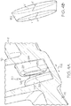
FIG. 2 is a top plan view, in cross-section, of the Venturi device ofFIG. 1 . -
FIG. 3 is a side, cross-sectional perspective view taken along a plane parallel to the central longitudinal axis B at the junction of the suction port in the Venturi device in a prior art Venturi device having circular transverse cross-sections in the motive section and the discharge section. -
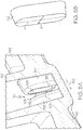
FIG. 4A is a side, cross-sectional perspective view taken along a plane parallel to the central longitudinal axis B at the junction of the suction port in the Venturi device ofFIG. 2 . -
FIG. 4B is a representation of the volume of the Venturi gap inFIG. 4A . -
FIG. 5A is a side, cross-sectional perspective view taken along a plane parallel to the central longitudinal axis B at the junction of the suction port in another embodiment of an Venturi device. -
FIG. 5B is a representation of the volume of the Venturi gap inFIG. 5A . -
FIG. 6 is a plan view looking into the Venturi device from the Venturi device outlet showing the offset between the motive outlet end and the discharge inlet end. -
FIG. 7 is a model of the internal passageway within the motive section of the Venturi device. -
FIG. 8 is a graphical representation comparing the Venturi device suction flow rates of a hyperboloid ellipse Venturi device disclosed herein against a conical circular Venturi device (prior art) at different selected manifold vacuum values. -
FIG. 9 is a graphical representation comparing the vacuum of a hyperboloid ellipse Venturi device disclosed herein against a conical circular aspirator (prior art) as the manifold vacuum increases. -
FIG. 10 is a graphical representation comparing the time to evacuate a canister by a hyperboloid ellipse Venturi device disclosed herein against a conical circular aspirator (prior art) as the manifold vacuum increases. -
FIG. 11 is a side, perspective view of a lower housing section of a Venturi device having a gate valve linearly translatable into the Venturi gap. -
FIG. 12 a top plan view of the suction port showing the gate valve in the closed position. -
FIG. 13 a top plan view of the suction port showing the gate valve in the open position. -
FIG. 14 is side, perspective view of the gate valve. -
FIG. 15 is a plan view of the back of the gate valve. -
FIG. 16 is a top plan view of the gate valve. -
FIG. 17 is a chart of data from a performance comparison of a gated Venturi device to a non-gated Venturi device under the same conditions. -
FIG. 18 is an unassembled, longitudinal cross-sectional view of an embodiment of the Venturi device. -
FIG. 19 is a side, longitudinal cross-sectional, plan view of another embodiment of a Venturi device. -
FIG. 20 is a side, perspective view of just the body of the Venturi device ofFIG. 19 . -
FIG. 21 is a detailed view of the Venturi gap of the Venturi device ofFIG. 19 . -
FIG. 22 is a side, perspective view of a second embodiment of a gate valve. -
FIG. 23 is an enlarged, longitudinal cross-section through the Venturi gap of the Venturi device ofFIG. 19 with the gate valve ofFIG. 22 inserted into the Venturi gap. - The following detailed description will illustrate the invention, examples of which are additionally illustrated in the accompanying drawings. In the drawings, like reference numbers indicate identical or functionally similar elements.
- As used herein "fluid" means any liquid, suspension, colloid, gas, plasma, or combinations thereof.
-
FIGS. 1 and2 illustrate different views of an Venturidevice 100. The Venturidevice 100 may be used in an engine, for example, in a vehicle's engine to provide vacuum to a device. InFIG. 1 the Venturidevice 100 is connected to adevice requiring vacuum 102, and the Venturidevice 100 creates vacuum for saiddevice 102 by the flow of air through apassageway 104, extending generally the length of the Venturi device, designed to create the Venturi effect. Venturidevice 100 includes abody 106 definingpassageway 104 and having three or more ports that are connectable to an engine or components connected thereto. The ports include: (1) amotive port 108, which may be connected to a source of clean air, e.g., from the engine intake air cleaner, that is positioned upstream of a throttle; (2) asuction port 110, which can connect via an optional check valve 111 to thedevice requiring vacuum 102; (3) anoutlet 112, which is connected to an engine intake manifold downstream of the throttle of the engine; and, optionally, (4) abypass port 114. Each of therespective ports connector feature 117 on the outer surface thereof for connecting the respective port to a hose or other component in the engine. - Check valve 111 is preferably arranged to prevent fluid from flowing from the
suction port 110 to theapplication device 102. In one embodiment, thedevice requiring vacuum 102 is a vehicle brake boost device, positive crankcase ventilation (PCV) device, or fuel purge device. In another embodiment, thedevice requiring vacuum 102 is a hydraulic valve. Thebypass port 114 may be connected to thedevice requiring vacuum 102 and, optionally, may include acheck valve 120 in thefluid flow path 122 therebetween.Check valve 120 is preferably arranged to control the flow of fluid to or from thebypass port 114 to theapplication device 102. - Referring now to
FIGS. 2 and 3 , the Venturidevice 100 is generally a "T-shaped" Venturi device defining an inner passageway along a central longitudinal axis B bisected by thesuction port 110. Theinner passageway 104 includes a first tapering portion 128 (also referred to herein as the motive cone) in themotive section 116 of thebody 106 coupled to a second tapering portion 129 (also referred to herein as the discharge cone) in thedischarge section 146 of thebody 106. Here, thefirst tapering portion 128 and the second taperingportion 129 are aligned end to end having themotive outlet end 132 facing thedischarge inlet end 134 and defining a Venturigap 152 therebetween, which defines a fluid junction placing thesuction port 110 in fluid communication with both themotive section 116 and thedischarge section 146 of theinner passageway 104. TheVenturi gap 152 as used herein means the lineal distance between themotive outlet end 132 and thedischarge inlet end 134. - When an Venturi device, such as
Venturi device 100, is for use in a vehicle engine, the vehicle manufacturer typically selects the size of both themotive port 108 andoutlet 112 based on the tubing/hose size available for connection of the Venturi device to the engine or components thereof. Additionally, the vehicle manufacturer typically selects the maximum motive flow rate available for use in the Venturi device, which in turn will dictate the area of the interior opening defined at themotive outlet end 132, i.e., themotive outlet 133. Accordingly, the vehicle manufacturer's selected parameters for the particular engine dictate the ratio of themotive outlet 133 to theoutlet 112. Working within these constraints, the disclosedVenturi devices 100 significantly reduce the compromise between the desire to produce high suction flow rates at low (5 kPa to 30 kPa) source/discharge pressures and increased depth of vacuum at higher (30 kPa to 60 kPa) source discharge pressures. This reduction in the compromise is accomplished by changing the configuration for themotive outlet 133 and the discharge inlet 135 (defined by the discharge inlet end 134) to increase the perimeter of theinner passageway 104 at themotive outlet end 132 and thedischarge inlet end 134, such as presented inFIGS. 5 and6 . - As illustrated in
FIGS. 5A-5B and6 , at least the interior surface of the motive outlet end 132 (the motive outlet 133) and the interior surface of the discharge inlet end 134 (the discharge inlet 135) are ellipse-shaped, but may alternately have a polygonal form. The interior of theinner passageway 104 extending away from themotive outlet end 132 and away from thedischarge inlet end 134, in opposite directions, from theVenturi gap 152, may be constructed to have the same general shape.FIG. 7 illustrates one embodiment of the shape of the internal passageway within the motive section of the Venturi device, but equally, if rotated 180 degrees illustrates the internal passageway within the discharge section. The internal passageway inFIG. 7 begins at themotive inlet end 130 as a circular opening having an area A1 and gradually, continuously transitions, as a hyperbolic or parabolic function, to an ellipse opening at themotive outlet 133 that has an area A2, which is smaller than A1. The circular opening at themotive inlet end 130 is connected to the ellipse-shapedmotive outlet 133 byhyperbola lines 170 that provide the advantage of flow lines at themotive outlet end 132 being parallel to one another. Themotive inlet end 130 and thedischarge outlet end 136 may also define ellipse-shaped or some other polygonal form openings at some point prior thereto and transition from said shapes to a circular cross-section to form a hose connecting portion, for example similar to hose-connectingportion 119, having connector features 117 on the exterior thereof. - To form the "T" shape of the
Venturi device 100 thesuction port 110 has a central longitudinal axis C generally perpendicular to the body's central longitudinal axis B. Theoptional bypass port 114 may likewise have a central longitudinal axis D that is generally perpendicular to the body's central longitudinal axis B. As illustrated inFIG. 1 , thebypass port 114 may intersect thesecond tapering section 129 adjacent to, but downstream of thedischarge outlet end 136. Thebody 106 may thereafter, i.e., downstream of this intersection of the bypass port, continue with a cylindrically uniform inner diameter until it terminates at theoutlet 112. In another embodiment (not shown), thebypass port 114 and/or thesuction port 110, rather than being perpendicular, may be canted relative to axis B and/or to one another. In the embodiment ofFIG. 2 , thesuction port 110 and thebypass port 114 are aligned with one another and have the same orientation relative to the body's central longitudinal axis B. In another embodiment, not shown, thesuction port 110 and thebypass port 114 may be offset from one another and can be positioned relative to components within the engine that they will connect to for ease of connection. - The
suction port 110 includes asuction inlet 138 and asuction outlet 135, which is thedischarge inlet 134, and similarly to thefirst tapering section 128, may gradually, continuously taper as a cone along its length from the larger dimensionedsuction inlet 138 to a smaller dimensionedsuction outlet 135 or it can be a generally cylindrical tube. Thebypass port 114, when present, may also gradually, continuously taper as a cone along its length, in particular from a smallerdimensioned end 162 to a largerdimensioned end 160, or it can be a generally cylindrical tube. Depending upon the attachment of the Venturi device into a system, thebypass port 114 may operate with the largerdimensioned end 160 as the inlet and the smallerdimensioned end 162 as the outlet or vice versa. - As best seen in
FIGS. 2 and5 , at the motive outlet end 132 of thefirst tapering portion 128, juxtaposed to thesecond tapering portion 129, thesuction port 110 includes an enlarged region defining a void 150 in fluid communication withVenturi gap 152 or conversely theVenturi gap 152 may be considered part ofvoid 150. The fluid junction of thesuction port 110 withinner passageway 104 is generally centered relative to theVenturi gap 152 and thevoid 150 is generally aligned with the suction port's central longitudinal axis C and transitions thefirst tapering portion 128 into thesecond tapering portion 129. The void 150 may be shaped as parallelepiped whose length is similar to the suction port's interior cross-section dimension(s), but whose bottom is an arcuate projection projecting downward away from thesuction port 110. In a cross-section taken transverse to the body's central longitudinal axis B along the suction port's central longitudinal axis C, the void is seen to be generally U-shaped around and/or over thedischarge inlet end 134 and themotive outlet end 132 as best understood by viewingFIGS. 2 ,4A , and5A in combination. As seen inFIGS. 2 and5A , the suction port extends downward around the sides of themotive outlet end 132 and the sides of thedischarge inlet end 134 and defines the void 150 between all sides thereof. As seen inFIG. 5A , the exterior profile of themotive outlet end 132 and thedischarge inlet end 134 both generally match their respective internal shapes. - In
Venturi device 100, the flow of motive air through thefirst tapering portion 128 increases its speed, which creates low static pressure in thevoid 150. This low static pressure draws air from thesuction port 110 into theVenturi gap 152 and into thedischarge section 146 through the discharge inlet (suction outlet) 135. - The
Venturi device 100 may be operated to meet the following geometric ratios:Representative Symbol Ratio A' suction inlet area / suction outlet area B' motive inlet area / motive outlet area C' discharge outlet area / discharge inlet area - There are also performance ratios as follows:
Representative Symbol Ratio F suction mass flow rate / motive mass flow rate G suction vacuum pressure / discharge vacuum pressure - To maximize the ratio F for the hyperbolical flow passageways disclosed herein, the ratio A' should be between 3 and 12, and the ratio B' should be greater than 4, and the ratio C' should be greater than 4.
- To maximize the ratio G for hyperbolical flow passageways, the ratio A' should be between 3 and 12, and the ratio B' should be greater than 4, and the ratio C' should be greater than 4.
- In the prior art of
FIG. 3 , the outlet end of the motive cone and the inlet end of the discharge cone each have circular internal cross-sections and circular exterior profiles and thereby define a Venturi gap that is a frustum having a circular outer periphery. From this drawing, one of the limitations to suction flow is illustrated - the area at the fluid junction of the suction port to the motive cone and the discharge cone. - In a desire to increase the flow rate of air from the suction port into the
Venturi gap 152 of the Venturi devices disclosed herein, the area of the Venturi gap is increased by increasing the perimeter of theoutlet end 132 and theinlet end 134 without increasing the overall inner dimension of thefirst tapering section 128 and the second tapering section 129 (preferably with no increase in the mass flow rate). In particular,motive outlet end 132 and dischargeinlet end 134 are changed from being circular to being non-circular as described above. There are an infinite number of possible shapes that are not circular, each with a perimeter and a cross sectional area. These include polygons, or straight-line segments connected to each other, non-circular curves, and even fractal curves. To minimize cost a curve is simpler and easy to manufacture and inspect, and has a desirable perimeter length. -
FIGS. 4A-AB and5A-5B illustrate embodiments with improved fluid junctions where thesuction port 110 meets themotive outlet end 132 and thedischarge inlet end 134. The smallest area of the flow path from thesuction port 110 to theVenturi gap 152 is the frustum defined between themotive outlet end 132 and thedischarge inlet end 134, seeFIGS. 4B and5B . InFIGS. 4A and 4B , theoutlet end 132 of themotive cone 128 and theinlet end 134 of thedischarge cone 129 each have inner and outer elliptical perimeters and thereby define aVenturi gap 152 that is a frustum having an elliptical outer periphery. InFIGS. 5A and 5B , theoutlet end 132 of themotive cone 128 and theinlet end 134 of thedischarge cone 129 each have inner and outer generally rectangular-shaped perimeters (with rounded corners) and thereby define aVenturi gap 152 that is a frustum having a generally rectangular-shaped outer periphery. While the embodiments in the figures have the same perimeter for theoutlet end 132 and theinlet end 134, i.e., both are elliptical or both are generally rectangular, theoutlet end 132 and theinlet end 134 may have differently shaped perimeters, i.e., one may be elliptical while the other is generally rectangular. Additionally, themotive outlet end 132 and thedischarge inlet end 134 may terminate with a rounded chamfer to improve the directionality of the flow of the fluid from thesuction port 110 in to thedischarge inlet end 134. - Additionally, as seen most clearly in
FIG. 6 , but is also seen in the frustums ofFIGS. 4B and5B , theoutlet end 132 of themotive cone 128 for each embodiment is dimensionally smaller than theinlet end 134 of thedischarge cone 129. This difference in dimension is identified as offset 140. InFIG. 4B , for example, the offset is seen in that the length of the major axis Y of themotive outlet end 132 is less than the length of the major axis Y' of thedischarge inlet end 134 and may also have a length of the minor axis X of themotive outlet end 132 that is less than the length of the minor axis X' of thedischarge inlet end 134. - In any of the elliptical- or polygonal-shaped embodiments, the elliptical- or polygonal-shaped internal cross-section of the motive outlet end of the converging motive section has a ratio of the major axis to the minor axis of about 2 to about 4, and the elliptical- or polygonal-shaped internal cross-section of the inlet end of the diverging discharge section is offset, relative to the elliptical- or polygonal-shaped internal cross-section of the outlet end of the converging motive section, by the ratio of the difference of the discharge inlet area and the motive outlet area to the peak motive flow rate, which is then multiplied by a constant k1 to have a unitless ratio of greater than 0.28.


- In any of the elliptical- or polygonal-shaped embodiments, the Venturi gap between the motive outlet end and the discharge inlet end has a gap ratio defined as the area of the Venturi gap divided by the motive flow times a constant k2 (to have a unitless ratio).


- In one embodiment, the elliptical- or polygonal-shaped internal cross-section of the
motive outlet end 132 has an eccentricity of between 0 to, and including 1. In another embodiment, the elliptical- or polygonal-shaped internal cross-section of the outlet end has an eccentricity of between about 0.4 to, and including about 0.97. - Referring again to
FIGS. 4A and 4B , theoutlet end 132 and theinlet end 134 are elliptical in profile thereby having a major axis (Y) and a minor axis (X). The equation of an ellipse can be defined as; X2 / B2 + Y2 / A2 = 12 Where A is the distance from the origin to the ellipse along the major axis Y and B is the distance from the origin to the ellipse along the minor axis X. The area of an ellipse is:


- Given a selected motive flow for the Venturi device design being chosen to be equivalent for calculations where the radius of the prior art circular Venturi device is 1 mm, the area is of 3.14 mm2 with a perimeter of 6.28 mm. The ratio of perimeter to area is mathematically equal to 2 for a circular internal cross-section for the motive outlet end and the discharge inlet end.
- For an ellipse of a given eccentricity we can compute the area, perimeter and the ratio of perimeter to cross sectional area in the disclosed embodiments. If we limit the area to be equal to that of a circle of radius of 1 mm, the calculated results are as follows;
TABLE 1 ellipse e A (mm) B (mm) h area (mm2) perimeter (mm) ratio perimeter to area (mm-1) 0.000 1.000 1.000 0.000 3.142 6.283 2.000 0.431 1.053 0.950 0.051 3.143 6.297 2.004 0.586 1.111 0.900 0.105 3.141 6.335 2.017 0.691 1.176 0.850 0.161 3.140 6.406 2.040 0.768 1.250 0.800 0.220 3.142 6.518 2.075 0.827 1.333 0.750 0.280 3.141 6.673 2.125 0.872 1.429 0.700 0.342 3.143 6.886 2.191 0.906 1.538 0.650 0.406 3.141 7.160 2.280 0.933 1.667 0.600 0.471 3.142 7.522 2.394 0.953 1.818 0.550 0.535 3.141 7.983 2.541 0.968 2.000 0.500 0.600 3.142 8.578 2.731 0.979 2.222 0.450 0.663 3.141 9.345 2.975 0.987 2.500 0.400 0.724 3.142 10.349 3.294 0.992 2.857 0.350 0.782 3.141 11.682 3.719 0.996 3.333 0.300 0.835 3.141 13.504 4.299 0.998 4.000 0.250 0.882 3.142 16.102 5.125 0.999 5.000 0.200 0.923 3.142 20.041 6.379 1.000 6.667 0.150 0.956 3.142 26.653 8.483 1.000 10.000 0.100 0.980 3.142 39.919 12.707 1.000 20.000 0.050 0.995 3.142 79.783 25.396 - So, by changing the eccentricity, the perimeter can be increased while holding the cross-sectional area fixed. This increase in perimeter provides the advantage of increasing the intersection area at the junction between the suction port, the motive cone, and the discharge cone, resulting in an increase in the suction port flow rate.
- Referring now to
FIGS. 5A and 5B , themotive outlet end 132 and thedischarge inlet end 134 are generally rectangular in profile thereby having a length and a width and hence two axes, a major axis U and a minor axis V. As illustrated, the Venturi device's generally rectangular profile for theoutlet end 132 andinlet end 134 include semicircular ends corresponding to the width of the rectangular portion. The orientation of the profile of the outlet and inlet ends 132, 134 should not be construed to be limited thereto. The area of this rectangle is equal to the sum of the areas of the two end semicircles plus the area of the straight section in between the semicircles. The perimeter of the rectangle is the lengths of the two sides plus the lengths of the semicircular ends. We can calculate the following;TABLE 2 Rectangle A (mm) B (mm) area (mm2) perimeter (mm) ratio of perimeter to area (mm-1) 1.000 1.000 3.142 6.283 2.000 1.272 0.950 3.142 6.614 2.105 1.563 0.900 3.142 6.981 2.222 1.876 0.850 3.142 7.392 2.353 2.214 0.800 3.142 7.854 2.500 2.583 0.750 3.142 8.378 2.667 2.989 0.700 3.142 8.976 2.857 3.441 0.650 3.142 9.666 3.077 3.951 0.600 3.142 10.472 3.333 4.534 0.550 3.142 11.424 3.636 5.212 0.500 3.142 12.566 4.000 6.018 0.450 3.142 13.963 4.444 6.997 0.400 3.142 15.708 5.000 8.226 0.350 3.142 17.952 5.714 9.829 0.300 3.142 20.944 6.667 12.031 0.250 3.142 25.133 8.000 15.280 0.200 3.142 31.416 10.000 20.623 0.150 3.142 41.888 13.333 31.202 0.100 3.142 62.832 20.000 62.725 0.050 3.142 125.664 40.000 - Changing from a circular cross section to a generally rectangular one with the same area results in an increase in the ratio of perimeter to area similarly to the elliptical profile described above. This increase in perimeter will again provide the advantage of increasing the intersection area between the Venturi gap and the suction port, resulting in an increase in suction port flow.
- Another way to increase suction flow would be to lengthen the distance between the
outlet end 132 of themotive cone 128 and theinlet end 134 of thedischarge cone 129. As the motive flow travels through the Venturi gap it mixes with suction air. This combined flow has the effect of increasing the static pressure towards the discharge end of the Venturi. Lengthening this distance offers diminishing returns, and because the motive flow is largely unconstrained in the Venturi, offers the risk of turbulence and flow disturbance, which would reduce the velocity and increase static pressure. Accordingly, the increase in perimeter described above is preferred over lengthening the distance, but the two could be combined to avoid the diminishing returns. - The Venturi devices disclosed herein may be molded as a monolithic body. In one embodiment, the Venturi devices are formed by injection molding.
- In one embodiment, the
Venturi gap 152 is a lineal distance proportional to the (motive mass flow rate)n, wherein n is 0.25 to 0.8, and the offset between the motive outlet and the discharge inlet is also proportional to the (motive mass flow rate)n, where n is 0.25 to 0.8, and the elliptical- or polygonal-shaped internal cross-section of the outlet end has an eccentricity of between 0 to, and including 1, or more preferably between about 0.4 to, and including about 0.97. When the Venturi device is included in a system having a device requiring higher amounts of vacuum, n for the Venturi gap and n for the offset may both be 0.4 to 0.6. In one embodiment, n for the Venturi gap and n for the offset are both 0.5 and the eccentricity is between about 0.4 to, and including 0.97. In another embodiment, the gap ratio is set at a value equal to the ellipse minor diameter when the ellipse major diameter divided by three is equal to the ellipse minor diameter, wherein each value is accurate to +/-10%. - In operation, for example when the Venturi device is connected into an engine, engine air, i.e. filtered air, can be connected to enter the Venturi device at the motive port. Air exiting the Venturi device at the discharge port can be connected to the engine air at a point where the pressure is lower than that of the motive port. The motion of the air from the motive to discharge port draws the air down the motive cone, which can be a straight cone or a hyperbolic profile as described above. The reduction in area causes the velocity of the air to increase. Because this is an enclosed space the laws of fluid mechanics state that the static pressure must decrease when the fluid velocity increases. The minimum cross-sectional area of the motive cone abuts the Venturi gap. As air continues to travel to the discharge port it travels through the discharge cone, which is either a straight cone or a hyperbolic profile. Optionally, the discharge region can continue as a straight or hyperbolic profile cone until it joins the discharge port, or it can transition to a simple cylindrical or tapered passage. The minimum cross-sectional area end of the discharge cone is larger than that of the minimum cross section area end of the motive cone. The larger area is to provide area for the flow of air from the suction port. This change in area down the discharge cone slows the air velocity down again, with a subsequent increase in its static pressure.
- The Venturi gap connects to the suction port, which exposes air in the suction port/passage to the same low static pressure that exists in the air passing at high velocity between the motive and discharge cones. The pressure created here can be lower than the pressure at the discharge port, which is known already to be lower than that at the motive port. This low pressure may be used for a variety of applications on a vehicle, such as for evacuating a vehicle brake boost canister, as is known to those skilled in the art. Under some circumstances, primarily when the gasoline engine is lightly loaded, the pressure at the discharge port is low enough to quickly lower the pressure at the application device. Since the area of the connection between the discharge cone or passage and the bypass passage is quite large relative to the connection between the suction passage and the Venturi gap, this optional connection can assist in evacuation of the application device initially.
- For a comparison study a 3 gps Venturi device having an elliptical motive outlet and an elliptical discharge inlet at the Venturi gap and a hyperboloid internal profile in the motive and discharge sections (referred to as the "hyperboloid ellipse Venturi device") as illustrated in
FIG. 7 was operated under conditions of 10 kPa manifold vacuum, 15 kPa manifold vacuum, and 20 kPa manifold vacuum with increasing brake boost canister vacuum and compared to a 3 gps conical circular Venturi device under the same conditions. A conical circular Venturi device is one that has a circular motive outlet and a circular discharge inlet and a conical internal profile in the motive and discharge sections. As evidenced by the data presented inFIG. 8 , the hyperboloid ellipse Venturi device provided a synergistic effect of the hyperboloid internal profile with the ellipse-shaped openings that exceeded the results of the conical circular Venturi device. At 10 kPa, 15 kPa, and 20 kPa manifold pressure, the hyperboloid ellipse Venturi device provided higher suction flow rates over an increasing range of brake boost canister vacuum from 12 kPa to about 67 kPa. Interestingly, at 15 kPa manifold pressure the hyperboloid ellipse Venturi device performed generally similar to the conical circular Venturi device when it was at 20 kPa manifold pressure, evidencing unexpected, superior performance. - Referring now to
FIGS. 9 and10 , the same Venturi devices compared forFIG. 8 were compared with respect to the ultimate vacuum the Venturi device could generate and the time needed for the Venturi device to evacuate a canister to create vacuum. For the tests, theoutlet 112 was in fluid communication with an intake manifold of the engine, the suction port was in fluid communication with a vehicle brake boost canister, and the motive inlet was connected to a source of clean air. As shown in the graph ofFIG. 9 , the hyperboloid ellipse Venturi device disclosed herein provides a deeper vacuum compared to the conical circular Venturi device under the same operating conditions, i.e., at 10, 15, and 20 kPa of manifold vacuum the hyperboloid ellipse Venturi device had an ultimate vacuum that was greater by at least 5 kPa. Additionally, as seen inFIG. 10 , the hyperboloid ellipse Venturi device was superior in evacuating a brake boost canister compared to the conical circular Venturi device. At a manifold vacuum pressure of 10 kPa, the hyperboloid ellipse Venturi device was over just under 4.5 seconds faster at evacuating the canister. At 15 kPa and 20 kPa of manifold vacuum the hyperboloid ellipse Venturi device was about 2 seconds faster. Faster evacuation times at lower manifold vacuum provides for faster reaction time and improved performance. But, as seen in these graphs, not only does the Venturi device with the hyperboloid elliptical profile have faster evacuation time, it also provides a deeper vacuum at manifold vacuums of 10, 15, and 20 kPa. This dual benefit was a surprising, unexpected result from changing the shapes of the motive outlet and the discharge inlet that defines the Venturi gap and using an internal passageway that changes/taper according to a hyperbolic function. - Turning now to
FIGS. 11-13 , any of the various embodiments of the Venturi device for generating vacuum described herein may include avalve gate 300 within theVenturi gap 252 to control the passage of fluid from themotive section 216 to thedischarge section 246. TheVenturi device 200 has a body, such aslower body 206 inFIG. 11 , defining a Venturi gap between anoutlet end 232 of the convergingmotive section 216 and aninlet end 234 of a divergingdischarge section 246, and asuction port 210 in fluid communication with theVenturi gap 252, agate valve 300 linearly translatable to open and close theVenturi gap 252, and anactuator 310 connected to thegate valve 300 to operatively move thegate valve 300 between an open position O (FIG. 13 ) and a closed position C (FIG. 12 ). The convergingmotive section 216 defines a circular-shapedmotive inlet 208 and defines an elliptical- or polygonal-shapedmotive outlet 233, and the divergingdischarge section 246 defines an elliptical- or polygonal-shapeddischarge inlet 235. - Each of the
respective ports connector feature 217 on the outer surface thereof for connecting the respective port to a hose or other component in the engine. Theother ports upper housing 204 tosuction port 210 and anactuator 310 to theport 282. Referring toFIG. 18 , theupper housing 204 and thelower housing 206, at the junction of thesuction port 210, may form acheck valve 211 having asealing disc 213 seated therein. Thefingers 218 extending upward away from thesuction port 210 of thelower body 206 define a seat for thesealing disc 213 for an open position of thecheck valve 211. Theupper housing 204 defines apassageway 220 leading to anentrance 222, which may comprise a plurality of openings, to achamber 224 of thecheck valve 211 and, hence, to thesuction chamber 250 of thelower body 206. - The
lower body 206 defines agate pocket 280 that transects a central longitudinal axis A of the convergingmotive section 216. Thegate pocket 280 terminates at the exterior of thelower body 206 with a connector 281 connectable to anactuator 310. Thegate pocket 280 has a trapezoid-shape, viewed in cross-section parallel to the central longitudinal axis A, that is wider at an end more proximate thesuction port 210 than at its opposite end. - With reference to
FIGS. 11-16 , thegate valve 300 is slidingly seated within thegate pocket 280. Thegate valve 300 is made of a thin piece of non-corroding metal or plastic folded, bent, or molded into a generally U-shaped continuous piece, viewed in longitudinal cross-section (FIG. 16 ), shaped to close off themotive exit 233 and thedischarge inlet 235 when in the closed position C ofFIG. 12 . The continuous, opposingsides suction port 210 at all times. Afirst side 302 of thegate valve 300 is in sealing engagement with theoutlet end 233 of the convergingmotive section 216 and thesecond side 304 is in sealing engagement with theinlet end 235 of the divergingsection 246. The opposingsides gate valve 300 each act as a leaf spring, biased generally away from one another to form the sealing engagements. In particular, in its free, uninstalled condition, the size, i.e., the distance from thesurface 302 to thesurface 304, as measured at either the top or bottom 314 or the top 312, is such that the surfaces touch theoutlet end 233 of the motive and theinlet end 235 of the discharge. This provides two benefits to this invention. Firstly, the drag created by the interference will ensure that thevalve 300 will remain fixed in position when in either the closed position C or the open position O. This will eliminate any wear that would occur if thevalve 300 was free to rattle about. Secondly, during operation, the difference in pressure between the motive port and the discharge port biases the gate always in the same direction, toward the discharge passage. By ensuring that thevalve 300 is biased against toward the discharge passage, potential leakage between the motive port and the discharge port is minimized. - As seen in
FIG. 15 , thegate valve 300 has a trapezoid-shaped back 306 that is wider at anend 312 more proximate thesuction port 210 than theopposite end 314. - In one embodiment, the
actuator 310 is a pneumatic actuator connected to the gate valve to operatively move the gate valve between the open position O and the closed position C. The pneumatic actuator may be operated using the very vacuum created by the Venturi device for a self-regulated system configuration. Example pneumatic actuators are discussed in co-pending U.S. applications Serial No.14/154,268 14/277,815 actuator 310 is an electromagnetic actuator connected to thegate valve 300 to operatively move the gate valve between an open position and a closed position, for example, a solenoid. An example solenoid is discussed in co-pending U.S. application Serial No.14/473,151 - As seen in
FIG. 11 , thegate valve 300 is positioned relative to the elliptical- or polygonal-shapedmotive outlet 233 for linear translation at the shortest stroke distance, which is in a plane parallel to a minor axis of themotive outlet 233. For example, a circular discharge inlet having a 4 mm radius has a stroke distance of 4 mm, but an ellipse-shaped discharge inlet having the same area as the 4 mm circle having a minor axis of 2.3 mm, only has a stroke distance of 2.3 mm. This is nearly half the distance for a circular discharge inlet. - In the illustrated embodiments of
FIGS. 11 and18 , thegate valve 300 is positioned to enter thesuction chamber 250 from the side of thelower body 206, rather than from the top or bottom of the lower body. This construction aligns thegate valve 300 with the minor axis of the ellipse-shaped discharge inlet and provides the shortest stroke distance, which reduces both the time to travel from the open position O to the closed position C or vice versa, as well as the size of the actuation device, either an electromagnet or pneumatic. - Moreover, referring to
FIG. 17 , unexpected results were found with the introduction of thegate valve 300 into the construction of thelower body 206. When the gate valve is present, compared to an equivalent Venturi device without a gate valve (i.e., a non-gated Venturi device), the flow in grams per second is higher by an increase of about 5.5% for a 10 kPa source vacuum and by an increase of about 2% for a 20 kPa source vacuum. Also, for the 10 kPa source vacuum, the suction vacuum increased by about 3%. The inventors expected the introduction of the gate to decrease performance slightly, but it actually improved the performance in at least one aspect under both 10 kPa and 20 kPa source vacuum, as shown inFIG. 17 . - Referring now to
FIGS. 19 and 20 , an alternate embodiment of a Venturi device, generally designated 400, is disclosed. TheVenturi device 400 is connected to adevice requiring vacuum 102, and includes abody 406 definingpassageway 404 and having a variety of ports including amotive port 408, a pair ofsuction ports aspirator outlet 412, asuction housing 407 connected to thebody 406 with fluidtight/airtight seals, for example by sonic welding, heating, or other conventional methods for forming such seals therebetween, and, optionally,dual bypass ports suction housing 407 and thebody 406, together, form check valve 420 and/or 421, which if present include a sealing member 411, 411', respectively. Additionally,Venturi device 400 includes afirst cap 409a and asecond cap 409b defining an end of thechamber 456 and an end ofchamber 466, respectively. The first andsecond caps caps body 406 may be molded such that these are integral closed chambers. - The
body 406 definespassageway 404 along a central longitudinal axis bisected by thesuction ports inner passageway 404 includes afirst tapering portion 428 and thesecond tapering portion 429 aligned end to end with themotive outlet end 432 facing thedischarge inlet end 434 and defining aVenturi gap 452 therebetween. Components of theVenturi device 400 not described below are understood to be analogous to those described above with respect to the other embodiments. - The
body 406 ofFIGS. 19 and 20 further defines achamber 456 spacing thefirst suction port 410a and thesecond suction port 410b apart from one another by a distance D400. Thechamber 456 includes a plurality offingers 442 extending radially inward and axially away (upward in the figures) from thepassageway 404 of thebody 406. The plurality offingers 442 are arranged radially as individual protrusions from an inner wall of thechamber 456 in an orientation where immediately adjacent neighboring fingers are spaced a distance apart from one another and define a void therebetween that is in fluid communication with thesecond suction port 410b. The plurality offingers 442 define a seat for the sealing member 411 as part of check valve 420. Similarly, thecheck valve 421, if the bypass port(s) 414a, 414b are present, has achamber 466 defined by thebody 406 that includes a plurality of fingers 442' extending radially inward and radially away (upward in the drawings) from thepassageway 404 of thebody 406 that collectively define a seat for the sealing member 411'. The plurality of fingers 442' are arranged radially as protrusion from an inner wall of thechamber 466 in an orientation where immediately adjacent neighboring fingers are spaced a distance apart from one another. Each of the plurality offingers 442, 442' has a base that is wider than at an apex thereof. The apexes of the plurality offingers 442 collectively define the seat for the sealing member 411 for an open position, and the apexes of fingers 442' define the seat for sealing member 411' for an open position. - Referring to
FIG. 20 , thebody 406 also includes aport 482 that defines agate pocket 480. Theport 482 and thegate pocket 480 transect the central longitudinal axis A of theVenturi device 400. Thegate pocket 480 may terminate at the exterior of thebody 406 with a connector connectable to an actuator as shown inFIG. 11 . Thegate pocket 480 is shaped to receive the gate valve 300' ofFIG. 22 and is generally hour-glass shaped as viewed from the port end. Thegate valve pocket 480 is positioned for the gate valve 300' to enter thesuction chamber 456 from the side of thebody 406, rather than from the top or bottom of the lower body. This construction aligns the gate valve 300' with the minor axis of the ellipse-shaped discharge inlet and provides the shortest stroke distance, which reduces both the time to travel from the open position O to the closed position C or vice versa, as well as the size of the actuation device, either an electromagnet or pneumatic. - Referring now to
FIG. 21 , theVenturi gap 452 between themotive outlet end 432 and thedischarge inlet end 434 is shown in greater detail. Thebody 406 further defines achamber 456 spacing thefirst suction port 410a and thesecond suction port 410b apart from one another by a distance D400 as labeled inFIGS. 19 and 20 . Theoutlet end 432 of the motive section extends into thechamber 456 at a position where thechamber 456 provides fluid flow around the entire outer surface of theoutlet end 432, and aninlet end 434 of thedischarge section 146 extends into thechamber 456 at a position where thechamber 456 provides fluid flow around the entire outer surface of theinlet end 434.Suction port 410a is positioned proximate atop portion 441 of themotive outlet end 432 and atop portion 443 of thedischarge inlet end 434, which define anupper portion 433 of theVenturi gap 452.Suction port 410b is positioned proximate alower portion 445 of themotive outlet end 432 and alower portion 447 of thedischarge inlet end 434, which define alower portion 435 of theVenturi gap 452. The width of theVenturi gap 452 tapers symmetrically from a maximum width W1 at the upper andlower portions Venturi gap 452 proximate thesuction ports center portion 437 thereof. As a result, the void defined by the Venturi gap 552 is symmetrical about a plane bisecting thepassageway 404 into upper andlower halves 457, 459 (in the illustrated embodiment, above and below axis B), thereby improving flow conditions and decreasing turbulence and resultant noise as fluid flows through theVenturi gap 452 as compared to aspirator systems incorporating Venturi gaps with asymmetrical (e.g., conical or tapered) configurations. - The
Venturi device 400, incorporating the pair ofsuction ports Venturi gap 452, also provides improved suction flow rate for a given motive flow and discharge pressure as compared to a system incorporating asingle suction port 410 because the disclosed system provides greater capacity to utilize the Venturi effect created by the motive flow throughpassageway 404. With continued reference toFIG. 21 ,arrows lower suction ports upper half 457 of thepassageway 404 across theVenturi gap 452 yield suction primarily alongflow path 453 throughsuction port 410a. Venturi forces generated by the motive flow through the lower half 459 of thepassageway 404 across theVenturi gap 452 yield suction primarily alongflow path 455 throughsuction port 410b. - With reference to
FIGS. 22 and 23 , the gate valve 300' is slidingly seated within thegate pocket 480 such that it is linearly translatable to open and close theVenturi gap 452. The gate valve 300' is made of a thin piece of non-corroding metal or plastic folded, bent, or molded into a generally U-shaped continuous piece, similar to the view ofFIG. 16 , shaped to close off the motive exit and the discharge inlet when in the closed position ofFIG. 23 , and has similar characteristics, advantages, and unexpected results to those described above forgate valve 300. The continuous, opposing sides 302', 304' are spaced apart a distance apart to define void 308' therebetween that is in fluid communication with thesuction ports suction ports - A Venturi device similar to those in
FIGS. 19-20 , but having a mirror check valve a second "upper"body 407 opposite the check valve 420 ofFIG. 19 , is disclosed inco-pending U.S. Application 14/734,228 in the embodiment illustrated inFIGS. 9-10 , which can also have aport 482 andpocket 480 for housing the gate valve 300'.
Claims (15)
- A Venturi device (100) for generating vacuum comprising:a body (106) defining a Venturi gap (152) between an outlet end (132) of a converging motive section (116) that defines a motive outlet (135) and an inlet end (134) of a diverging discharge section (146) that defines a discharge inlet (235); anda suction port (110) in fluid communication with the Venturi gap (152) characterized in that it further comprisesa gate valve (300) linearly translatable to open and close the Venturi gap (152), the gate valve (300) being generally a U-shaped continuous piece , thereby having continuous, opposing sides that each close the motive outlet (135) and the discharge inlet (235) such that there is no flow therebetween when the gate valve (300) is in a closed position, wherein the continuous opposing sides are spaced apart a distance to define a gate valve void (308) between the opposing sides that is in fluid communication with the suction port (110); andan actuator (310) connected to the gate valve (300) to operatively move the gate valve (300) between an open position and the closed position.
- The Venturi device of claim 1, wherein the opposing sides of the gate valve (300) each act as a leaf spring, biased generally away from one another.
- The Venturi device of claim 1, defining a gate pocket (480) that transects a central longitudinal axis of the converging motive section (116), the gate valve (300) slidingly seated within the gate pocket (480).
- The Venturi device of claim 3, wherein the gate valve (300) has a trapezoid-shaped back that is wider at an end more proximate the suction port (110) or has a generally hour-glass-shaped back that is wider at opposing ends than in a middle region.
- The Venturi device of claim 1, wherein the motive outlet (135) is elliptical- or polygonal-shaped, and the discharge inlet (235) is elliptical- or polygonal-shaped; wherein elliptical-shaped has an eccentricity greater than 0.
- The Venturi device of claim 5, wherein the gate valve (300) is positioned relative to the elliptical- or polygonal-shaped motive outlet (135) for linear translation at a shortest stroke distance in a plane parallel to a minor axis of the motive outlet (135).
- The Venturi device of claim 5, wherein the converging motive section (116) defines an inner passageway (104, 404) that transitions as a hyperbolic function from a circular-shaped motive inlet to the elliptical- or polygonal-shaped motive outlet (135), and wherein the elliptical- or polygonal-shaped motive outlet (135) has an area that is less than the area of the circular-shaped motive inlet.
- The Venturi device of claim 5, wherein the Venturi gap (152) is proportional to the (motive mass flow rate)n, wherein n is within the range of 0.25 to 0.8.
- The Venturi device of claim 1, wherein the actuator (310) is a pneumatic actuator or a solenoid actuator connected to the gate valve (300) to operatively move the gate valve (300) between the open position and the closed position.
- The Venturi device of claim 1, wherein the suction port (110) extends downward around the sides of the outlet end (132) of the converging motive section (116) and the sides of the inlet end (134) of the diverging discharge section (146); and wherein the exterior profile of the outlet end (132) of the converging motive section (116) and the inlet end (134) of the diverging discharge section (146) generally match their respective internal shapes.
- A system comprising the Venturi device (100) of any of the preceding claims having the suction port (110) in fluid communication with a device requiring vacuum and the converging motive section (116) in fluid communication with a source of fluid.
- The system of claim 11, wherein the source of fluid is a compressor of a super- or turbocharger in an internal combustion engine.
- The system of claim 12, wherein the diverging discharge section (146) defines a discharge exit opposite the inlet end (134), wherein the discharge exit is in fluid communication with an intake manifold of the internal combustion engine.
- The system of claim 11, wherein the source of fluid is atmospheric air from an air intake filter in an internal combustion engine.
- The system of claim 14, wherein a discharge exit is in fluid communication with an intake manifold of the internal combustion engine.
Applications Claiming Priority (2)
| Application Number | Priority Date | Filing Date | Title |
|---|---|---|---|
| US201662397477P | 2016-09-21 | 2016-09-21 | |
| PCT/US2017/052642 WO2018057692A1 (en) | 2016-09-21 | 2017-09-21 | Valve gate within a venturi gap of a venturi device for producing vacuum |
Publications (3)
| Publication Number | Publication Date |
|---|---|
| EP3516275A1 EP3516275A1 (en) | 2019-07-31 |
| EP3516275A4 EP3516275A4 (en) | 2020-04-01 |
| EP3516275B1 true EP3516275B1 (en) | 2021-06-23 |
Family
ID=61618427
Family Applications (1)
| Application Number | Title | Priority Date | Filing Date |
|---|---|---|---|
| EP17853857.5A Active EP3516275B1 (en) | 2016-09-21 | 2017-09-21 | Valve gate within a venturi gap of a venturi device for producing vacuum |
Country Status (7)
| Country | Link |
|---|---|
| US (1) | US10571030B2 (en) |
| EP (1) | EP3516275B1 (en) |
| JP (1) | JP7008691B2 (en) |
| KR (1) | KR102360316B1 (en) |
| CN (1) | CN109715998B (en) |
| BR (1) | BR112019005619A2 (en) |
| WO (1) | WO2018057692A1 (en) |
Families Citing this family (6)
| Publication number | Priority date | Publication date | Assignee | Title |
|---|---|---|---|---|
| WO2018013668A1 (en) | 2016-07-12 | 2018-01-18 | Alexander Poltorak | System and method for maintaining efficiency of a heat sink |
| KR20210002510A (en) | 2018-04-23 | 2021-01-08 | 데이코 아이피 홀딩스 엘엘시 | Check valve insert defining the open position and check valve equipped with the same |
| CA3132362A1 (en) | 2019-04-11 | 2020-10-15 | Hsiao Chang Li | Universal rough-in valve and manifold |
| US11713816B1 (en) | 2019-08-22 | 2023-08-01 | Colt Irrigation, LLC | Pressure loss mitigation and durable valve |
| CN111980830B (en) * | 2020-10-12 | 2021-11-09 | 天津艾力特汽车科技有限公司 | Venturi integrated valve of evaporative emission system |
| US11408380B2 (en) * | 2020-12-24 | 2022-08-09 | Dayco Ip Holdings, Llc | Devices for producing vacuum using the Venturi effect having a hollow fletch |
Family Cites Families (41)
| Publication number | Priority date | Publication date | Assignee | Title |
|---|---|---|---|---|
| US1552614A (en) * | 1925-05-04 | 1925-09-08 | Ohio Brass Co | Valve |
| US1708805A (en) * | 1928-01-24 | 1929-04-09 | Errett G Smith | Valve installation |
| US2195923A (en) * | 1939-02-10 | 1940-04-02 | Lunkenheimer Co | Valve and flexible gate |
| US2582877A (en) * | 1948-07-02 | 1952-01-15 | Lev A Mekler | Valve closure |
| US2693110A (en) * | 1951-05-07 | 1954-11-02 | Charles E Terrell | Valve embodying fluid measuring means |
| US2964289A (en) * | 1957-07-23 | 1960-12-13 | Schmitz Friedrich | Diaphragm slide valve |
| US3537681A (en) * | 1968-01-24 | 1970-11-03 | Kerotest Mfg Corp | Valve gate with deflectable faces |
| US3666231A (en) * | 1969-03-10 | 1972-05-30 | Fiat Spa | Sealed valve with electromagnetic action |
| US3728891A (en) | 1970-10-07 | 1973-04-24 | Raymond P Wolgast | Vacuum cup |
| US3658087A (en) * | 1971-02-08 | 1972-04-25 | Acf Ind Inc | Valve with integral closure and seat carrier unit |
| US3933339A (en) * | 1972-11-11 | 1976-01-20 | Suddeutsche Kuhlerfabrik, Julius Fr. Behr | Water faucet with slider |
| GB1465953A (en) * | 1974-04-04 | 1977-03-02 | Hopkinsons Ltd | Valves |
| US4301993A (en) * | 1979-10-09 | 1981-11-24 | Consolidated Controls Corporation | Gate valve |
| US4519423A (en) * | 1983-07-08 | 1985-05-28 | University Of Southern California | Mixing apparatus using a noncircular jet of small aspect ratio |
| US5040576A (en) | 1985-12-02 | 1991-08-20 | Tokheim Corporation | Vapor passage fuel blockage removal |
| CA2019030C (en) | 1989-10-13 | 2000-10-31 | John Howard Stanley | Combination hose coupling and suction pump |
| DE4414176A1 (en) * | 1994-04-22 | 1995-10-26 | Zimmermann & Jansen Gmbh | Knife gate valve |
| US5707560A (en) * | 1996-08-12 | 1998-01-13 | Dynojet Research, Inc. | Constant velocity carburetor with variable venturi slide having bleed holes at an oblique angle and method of operation |
| US6035881A (en) * | 1997-05-15 | 2000-03-14 | Walter Alfmeier Ag Prazisions-Baugruppenelemente | Checkvalve unit |
| US6672570B2 (en) * | 2000-11-17 | 2004-01-06 | Walbro Japan, Inc. | Variable venturi carburetor |
| US20080057848A1 (en) * | 2006-08-31 | 2008-03-06 | Honeywell International, Inc. | Venturi gate valve assembly for an auxiliary power unit |
| US8657256B2 (en) * | 2010-01-25 | 2014-02-25 | Vat Holding Ag | Vacuum valve |
| WO2012145113A1 (en) * | 2011-04-18 | 2012-10-26 | Siemens Corporation | Methods for deblending of seismic shot gathers |
| US10337628B2 (en) * | 2012-02-20 | 2019-07-02 | Nyloncraft Incorporated | High mass flow check valve aspirator |
| US9097149B2 (en) * | 2012-07-13 | 2015-08-04 | Ford Global Technologies, Llc | Aspirator for crankcase ventilation and vacuum generation |
| US9435300B2 (en) * | 2012-12-13 | 2016-09-06 | Ford Global Technologies, Llc | Method and system for vacuum generation |
| US9441557B2 (en) * | 2012-12-13 | 2016-09-13 | Ford Global Technologies, Llc | Method and system for vacuum generation |
| US9845899B2 (en) | 2013-05-31 | 2017-12-19 | Dayco Ip Holdings, Llc | Sprung gate valves movable by an actuator |
| US9827963B2 (en) | 2013-06-11 | 2017-11-28 | Dayco Ip Holdings, Llc | Aspirators for producing vacuum using the Venturi effect |
| US9191209B2 (en) * | 2013-06-25 | 2015-11-17 | Google Inc. | Efficient communication for devices of a home network |
| BR112016004122B1 (en) | 2013-08-30 | 2022-05-17 | Dayco Ip Holdings, Llc | VALVE DEVICE AND METHOD FOR ASSEMBLY OF A VALVE ACTUATOR ASSEMBLY FOR COUNTER BLOW |
| WO2015054372A2 (en) * | 2013-10-08 | 2015-04-16 | Dayco Ip Holdings, Llc | Noise attenuation in a check valve unit or apparatus for producing vacuum |
| US10221867B2 (en) | 2013-12-10 | 2019-03-05 | Dayco Ip Holdings, Llc | Flow control for aspirators producing vacuum using the venturi effect |
| US9822785B2 (en) | 2013-12-11 | 2017-11-21 | Dayco Ip Holdings, Llc | Turbocharger compressor recirculation system |
| WO2015109306A1 (en) | 2014-01-20 | 2015-07-23 | Dayco Ip Holdings, Llc | Check valve with improved sealing member |
| KR20160122176A (en) * | 2014-02-17 | 2016-10-21 | 나일론크래프트, 인코퍼레이티드 | Super aspirator with integrated dual flow shut off |
| CN105378358B8 (en) | 2014-04-04 | 2018-04-24 | 戴科知识产权控股有限责任公司 | Bypass check valve and the Venturi with the bypass check valve |
| EP3148852B1 (en) * | 2014-05-30 | 2021-03-24 | Dayco IP Holdings, LLC | Vacuum creation system having an ejector, pneumatic control valve and optionally an aspirator |
| EP3152489B1 (en) | 2014-06-09 | 2018-11-07 | Dayco IP Holdings, LLC | Venturi devices with dual venturi flow paths |
| US9828953B2 (en) * | 2014-12-01 | 2017-11-28 | Dayco Ip Holdings, Llc | Evacuator system having multi-port evacuator |
| KR102498930B1 (en) * | 2015-03-09 | 2023-02-10 | 데이코 아이피 홀딩스 엘엘시 | Vacuum generating device using the Venturi effect |
-
2017
- 2017-09-21 JP JP2019515573A patent/JP7008691B2/en active Active
- 2017-09-21 KR KR1020197007544A patent/KR102360316B1/en active IP Right Grant
- 2017-09-21 WO PCT/US2017/052642 patent/WO2018057692A1/en unknown
- 2017-09-21 EP EP17853857.5A patent/EP3516275B1/en active Active
- 2017-09-21 CN CN201780057820.6A patent/CN109715998B/en active Active
- 2017-09-21 BR BR112019005619A patent/BR112019005619A2/en not_active Application Discontinuation
- 2017-09-21 US US15/711,108 patent/US10571030B2/en active Active
Non-Patent Citations (1)
| Title |
|---|
| None * |
Also Published As
| Publication number | Publication date |
|---|---|
| EP3516275A4 (en) | 2020-04-01 |
| US20180080567A1 (en) | 2018-03-22 |
| CN109715998A (en) | 2019-05-03 |
| CN109715998B (en) | 2020-09-29 |
| EP3516275A1 (en) | 2019-07-31 |
| JP2019534970A (en) | 2019-12-05 |
| WO2018057692A1 (en) | 2018-03-29 |
| KR102360316B1 (en) | 2022-02-08 |
| BR112019005619A2 (en) | 2019-06-18 |
| US10571030B2 (en) | 2020-02-25 |
| KR20190057055A (en) | 2019-05-27 |
| JP7008691B2 (en) | 2022-01-25 |
Similar Documents
| Publication | Publication Date | Title |
|---|---|---|
| EP3516275B1 (en) | Valve gate within a venturi gap of a venturi device for producing vacuum | |
| EP3007949B1 (en) | Aspirators for producing vacuum using the venturi effect | |
| EP3784939B1 (en) | A check valve insert defining an open position and check valves having same | |
| EP3283025B1 (en) | Devices for producing vacuum using the venturi effect | |
| US20150204452A1 (en) | Check valve with improved sealing member | |
| EP3268617B1 (en) | Device for producing vacuum using the venturi effect | |
| EP3478546B1 (en) | Bypass valve in an apparatus for producing vacuum | |
| US11614098B2 (en) | Devices for producing vacuum using the Venturi effect having a solid fletch | |
| US11408380B2 (en) | Devices for producing vacuum using the Venturi effect having a hollow fletch |
Legal Events
| Date | Code | Title | Description |
|---|---|---|---|
| STAA | Information on the status of an ep patent application or granted ep patent |
Free format text: STATUS: THE INTERNATIONAL PUBLICATION HAS BEEN MADE |
|
| PUAI | Public reference made under article 153(3) epc to a published international application that has entered the european phase |
Free format text: ORIGINAL CODE: 0009012 |
|
| STAA | Information on the status of an ep patent application or granted ep patent |
Free format text: STATUS: REQUEST FOR EXAMINATION WAS MADE |
|
| 17P | Request for examination filed |
Effective date: 20190416 |
|
| AK | Designated contracting states |
Kind code of ref document: A1 Designated state(s): AL AT BE BG CH CY CZ DE DK EE ES FI FR GB GR HR HU IE IS IT LI LT LU LV MC MK MT NL NO PL PT RO RS SE SI SK SM TR |
|
| AX | Request for extension of the european patent |
Extension state: BA ME |
|
| DAV | Request for validation of the european patent (deleted) | ||
| DAX | Request for extension of the european patent (deleted) | ||
| REG | Reference to a national code |
Ref country code: DE Ref legal event code: R079 Ref document number: 602017040994 Country of ref document: DE Free format text: PREVIOUS MAIN CLASS: F16K0003180000 Ipc: F02M0035100000 |
|
| A4 | Supplementary search report drawn up and despatched |
Effective date: 20200302 |
|
| RIC1 | Information provided on ipc code assigned before grant |
Ipc: F16K 3/18 20060101ALI20200225BHEP Ipc: F16K 3/00 20060101ALI20200225BHEP Ipc: F16K 3/14 20060101ALI20200225BHEP Ipc: F02M 35/10 20060101AFI20200225BHEP Ipc: F16K 3/30 20060101ALI20200225BHEP Ipc: F16K 3/02 20060101ALI20200225BHEP |
|
| GRAP | Despatch of communication of intention to grant a patent |
Free format text: ORIGINAL CODE: EPIDOSNIGR1 |
|
| STAA | Information on the status of an ep patent application or granted ep patent |
Free format text: STATUS: GRANT OF PATENT IS INTENDED |
|
| INTG | Intention to grant announced |
Effective date: 20210114 |
|
| GRAS | Grant fee paid |
Free format text: ORIGINAL CODE: EPIDOSNIGR3 |
|
| GRAA | (expected) grant |
Free format text: ORIGINAL CODE: 0009210 |
|
| STAA | Information on the status of an ep patent application or granted ep patent |
Free format text: STATUS: THE PATENT HAS BEEN GRANTED |
|
| AK | Designated contracting states |
Kind code of ref document: B1 Designated state(s): AL AT BE BG CH CY CZ DE DK EE ES FI FR GB GR HR HU IE IS IT LI LT LU LV MC MK MT NL NO PL PT RO RS SE SI SK SM TR |
|
| REG | Reference to a national code |
Ref country code: GB Ref legal event code: FG4D |
|
| REG | Reference to a national code |
Ref country code: CH Ref legal event code: EP |
|
| REG | Reference to a national code |
Ref country code: DE Ref legal event code: R096 Ref document number: 602017040994 Country of ref document: DE Ref country code: AT Ref legal event code: REF Ref document number: 1404521 Country of ref document: AT Kind code of ref document: T Effective date: 20210715 |
|
| REG | Reference to a national code |
Ref country code: IE Ref legal event code: FG4D |
|
| REG | Reference to a national code |
Ref country code: LT Ref legal event code: MG9D |
|
| PG25 | Lapsed in a contracting state [announced via postgrant information from national office to epo] |
Ref country code: LT Free format text: LAPSE BECAUSE OF FAILURE TO SUBMIT A TRANSLATION OF THE DESCRIPTION OR TO PAY THE FEE WITHIN THE PRESCRIBED TIME-LIMIT Effective date: 20210623 Ref country code: FI Free format text: LAPSE BECAUSE OF FAILURE TO SUBMIT A TRANSLATION OF THE DESCRIPTION OR TO PAY THE FEE WITHIN THE PRESCRIBED TIME-LIMIT Effective date: 20210623 Ref country code: HR Free format text: LAPSE BECAUSE OF FAILURE TO SUBMIT A TRANSLATION OF THE DESCRIPTION OR TO PAY THE FEE WITHIN THE PRESCRIBED TIME-LIMIT Effective date: 20210623 Ref country code: BG Free format text: LAPSE BECAUSE OF FAILURE TO SUBMIT A TRANSLATION OF THE DESCRIPTION OR TO PAY THE FEE WITHIN THE PRESCRIBED TIME-LIMIT Effective date: 20210923 |
|
| REG | Reference to a national code |
Ref country code: AT Ref legal event code: MK05 Ref document number: 1404521 Country of ref document: AT Kind code of ref document: T Effective date: 20210623 |
|
| PG25 | Lapsed in a contracting state [announced via postgrant information from national office to epo] |
Ref country code: GR Free format text: LAPSE BECAUSE OF FAILURE TO SUBMIT A TRANSLATION OF THE DESCRIPTION OR TO PAY THE FEE WITHIN THE PRESCRIBED TIME-LIMIT Effective date: 20210924 Ref country code: SE Free format text: LAPSE BECAUSE OF FAILURE TO SUBMIT A TRANSLATION OF THE DESCRIPTION OR TO PAY THE FEE WITHIN THE PRESCRIBED TIME-LIMIT Effective date: 20210623 Ref country code: RS Free format text: LAPSE BECAUSE OF FAILURE TO SUBMIT A TRANSLATION OF THE DESCRIPTION OR TO PAY THE FEE WITHIN THE PRESCRIBED TIME-LIMIT Effective date: 20210623 Ref country code: LV Free format text: LAPSE BECAUSE OF FAILURE TO SUBMIT A TRANSLATION OF THE DESCRIPTION OR TO PAY THE FEE WITHIN THE PRESCRIBED TIME-LIMIT Effective date: 20210623 Ref country code: NO Free format text: LAPSE BECAUSE OF FAILURE TO SUBMIT A TRANSLATION OF THE DESCRIPTION OR TO PAY THE FEE WITHIN THE PRESCRIBED TIME-LIMIT Effective date: 20210923 |
|
| REG | Reference to a national code |
Ref country code: NL Ref legal event code: MP Effective date: 20210623 |
|
| PG25 | Lapsed in a contracting state [announced via postgrant information from national office to epo] |
Ref country code: SM Free format text: LAPSE BECAUSE OF FAILURE TO SUBMIT A TRANSLATION OF THE DESCRIPTION OR TO PAY THE FEE WITHIN THE PRESCRIBED TIME-LIMIT Effective date: 20210623 Ref country code: SK Free format text: LAPSE BECAUSE OF FAILURE TO SUBMIT A TRANSLATION OF THE DESCRIPTION OR TO PAY THE FEE WITHIN THE PRESCRIBED TIME-LIMIT Effective date: 20210623 Ref country code: ES Free format text: LAPSE BECAUSE OF FAILURE TO SUBMIT A TRANSLATION OF THE DESCRIPTION OR TO PAY THE FEE WITHIN THE PRESCRIBED TIME-LIMIT Effective date: 20210623 Ref country code: EE Free format text: LAPSE BECAUSE OF FAILURE TO SUBMIT A TRANSLATION OF THE DESCRIPTION OR TO PAY THE FEE WITHIN THE PRESCRIBED TIME-LIMIT Effective date: 20210623 Ref country code: AT Free format text: LAPSE BECAUSE OF FAILURE TO SUBMIT A TRANSLATION OF THE DESCRIPTION OR TO PAY THE FEE WITHIN THE PRESCRIBED TIME-LIMIT Effective date: 20210623 Ref country code: CZ Free format text: LAPSE BECAUSE OF FAILURE TO SUBMIT A TRANSLATION OF THE DESCRIPTION OR TO PAY THE FEE WITHIN THE PRESCRIBED TIME-LIMIT Effective date: 20210623 Ref country code: PT Free format text: LAPSE BECAUSE OF FAILURE TO SUBMIT A TRANSLATION OF THE DESCRIPTION OR TO PAY THE FEE WITHIN THE PRESCRIBED TIME-LIMIT Effective date: 20211025 Ref country code: NL Free format text: LAPSE BECAUSE OF FAILURE TO SUBMIT A TRANSLATION OF THE DESCRIPTION OR TO PAY THE FEE WITHIN THE PRESCRIBED TIME-LIMIT Effective date: 20210623 Ref country code: RO Free format text: LAPSE BECAUSE OF FAILURE TO SUBMIT A TRANSLATION OF THE DESCRIPTION OR TO PAY THE FEE WITHIN THE PRESCRIBED TIME-LIMIT Effective date: 20210623 |
|
| PG25 | Lapsed in a contracting state [announced via postgrant information from national office to epo] |
Ref country code: PL Free format text: LAPSE BECAUSE OF FAILURE TO SUBMIT A TRANSLATION OF THE DESCRIPTION OR TO PAY THE FEE WITHIN THE PRESCRIBED TIME-LIMIT Effective date: 20210623 |
|
| REG | Reference to a national code |
Ref country code: DE Ref legal event code: R097 Ref document number: 602017040994 Country of ref document: DE |
|
| PG25 | Lapsed in a contracting state [announced via postgrant information from national office to epo] |
Ref country code: DK Free format text: LAPSE BECAUSE OF FAILURE TO SUBMIT A TRANSLATION OF THE DESCRIPTION OR TO PAY THE FEE WITHIN THE PRESCRIBED TIME-LIMIT Effective date: 20210623 |
|
| PLBE | No opposition filed within time limit |
Free format text: ORIGINAL CODE: 0009261 |
|
| REG | Reference to a national code |
Ref country code: CH Ref legal event code: PL |
|
| STAA | Information on the status of an ep patent application or granted ep patent |
Free format text: STATUS: NO OPPOSITION FILED WITHIN TIME LIMIT |
|
| REG | Reference to a national code |
Ref country code: BE Ref legal event code: MM Effective date: 20210930 |
|
| GBPC | Gb: european patent ceased through non-payment of renewal fee |
Effective date: 20210923 |
|
| 26N | No opposition filed |
Effective date: 20220324 |
|
| PG25 | Lapsed in a contracting state [announced via postgrant information from national office to epo] |
Ref country code: MC Free format text: LAPSE BECAUSE OF FAILURE TO SUBMIT A TRANSLATION OF THE DESCRIPTION OR TO PAY THE FEE WITHIN THE PRESCRIBED TIME-LIMIT Effective date: 20210623 Ref country code: AL Free format text: LAPSE BECAUSE OF FAILURE TO SUBMIT A TRANSLATION OF THE DESCRIPTION OR TO PAY THE FEE WITHIN THE PRESCRIBED TIME-LIMIT Effective date: 20210623 |
|
| PG25 | Lapsed in a contracting state [announced via postgrant information from national office to epo] |
Ref country code: LU Free format text: LAPSE BECAUSE OF NON-PAYMENT OF DUE FEES Effective date: 20210921 Ref country code: IT Free format text: LAPSE BECAUSE OF FAILURE TO SUBMIT A TRANSLATION OF THE DESCRIPTION OR TO PAY THE FEE WITHIN THE PRESCRIBED TIME-LIMIT Effective date: 20210623 Ref country code: IE Free format text: LAPSE BECAUSE OF NON-PAYMENT OF DUE FEES Effective date: 20210921 Ref country code: GB Free format text: LAPSE BECAUSE OF NON-PAYMENT OF DUE FEES Effective date: 20210923 Ref country code: FR Free format text: LAPSE BECAUSE OF NON-PAYMENT OF DUE FEES Effective date: 20210930 Ref country code: BE Free format text: LAPSE BECAUSE OF NON-PAYMENT OF DUE FEES Effective date: 20210930 |
|
| PG25 | Lapsed in a contracting state [announced via postgrant information from national office to epo] |
Ref country code: LI Free format text: LAPSE BECAUSE OF NON-PAYMENT OF DUE FEES Effective date: 20210930 Ref country code: CH Free format text: LAPSE BECAUSE OF NON-PAYMENT OF DUE FEES Effective date: 20210930 |
|
| P01 | Opt-out of the competence of the unified patent court (upc) registered |
Effective date: 20230522 |
|
| PG25 | Lapsed in a contracting state [announced via postgrant information from national office to epo] |
Ref country code: CY Free format text: LAPSE BECAUSE OF FAILURE TO SUBMIT A TRANSLATION OF THE DESCRIPTION OR TO PAY THE FEE WITHIN THE PRESCRIBED TIME-LIMIT Effective date: 20210623 |
|
| PG25 | Lapsed in a contracting state [announced via postgrant information from national office to epo] |
Ref country code: HU Free format text: LAPSE BECAUSE OF FAILURE TO SUBMIT A TRANSLATION OF THE DESCRIPTION OR TO PAY THE FEE WITHIN THE PRESCRIBED TIME-LIMIT; INVALID AB INITIO Effective date: 20170921 |
|
| PGFP | Annual fee paid to national office [announced via postgrant information from national office to epo] |
Ref country code: DE Payment date: 20230821 Year of fee payment: 7 |